

Page 1
®
Limit
USER´S MANUAL
Version 2.19 january 2019
www.mrcaudio.com
Page 2

SECURITY ADVICE
1
Category I device.
All sockets are isolated from mains
Always use the earth lead in mains cord
Keep these instructions. Heed all warnings. Follow all instructions.
Do not expose this device to rain or moisture. Do not use this apparatus near water - for
example, swimming pool, fountain. Do not place any objects containing liquids, such as
bottles or glasses, on the top of the unit. Do not splash liquids on the unit.
Clean only with a dry cloth. Do not use any solvent based cleaners.
Do not install near any heat sources such as radiators, heat fans, stoves, or other
apparatus that produce heat.
Never disconnect or disable the grounding of the power cord. Make sure that the base
where you connect it has a good grounding.
Always connect the equipment to an adequately protected voltage socket with safety
elements and easy access.
Unplug this apparatus during lightning storms, earthquakes or when unused for long
periods of time.
No user serviceable parts inside. Refer all servicing to qualified service personnel.
Servicing is required when the apparatus has been damaged in any way, such as powersupply cord or plug is damaged, liquid has been spilled or objects have fallen into the
apparatus, the apparatus has been exposed to rain or moisture, does not operate
normally, or has been dropped.
TO REDUCE THE RISK OF FIRE REPLACE THE MAINS FUSE ONLY WITH A FUSE
THAT CONFORMS TO IEC127-2. 250 VOLTS WORKING, TIME DELAY TYPE AND
BODY SIZE OF 20mm x 5mm. THE MAINS INPUT FUSE MUST BE RATED AT 230V=T
3,15AL and 115V=T 6,3AL.
MRC AUDIO EQLimit
2
Page 3

CONTENTS
2
Chap. Pag.
1 Security Advice 2
2 Contents 3
3 Introduction 4 - 5
Block diagram 6
4 Description 7 - 8
5 Installation 9
5.1 Connections 10
5.2 SCL software installation 11
5.3 Limiter Password 11
5.4 Master Password 12
6 Cinfiguring panels 13
User´s Data 14
Installations 15
User´s manual 16
Backup 16
7 Programming 17 - 18
7.1 Installation File 19
7.2 Limiter adjust 20 - 21 - 22
7.3 Levels and Timetable 23 - 24 - 25
7.3.1 AUX Levels and Timetable 25
7.4 Limiter 26
7.4.1 Calibration process 27 - 28
7.5 Display 29
7.6 Isolation 30 - 31- 32 - 33
7.7 Registry 34
7.8 Events List 35 - 36 - 37 - 38 - 39 - 40
7.9 Graphs 40 - 41
7.10 Preferences 42 - 43 - 44
8 Technical characteristics 45
9 Warranty 46
10 Remote Display DD-1 47
11 Remote Display DD-3 48 - 49 - 50
12 Certification 51 - 52 - 53
MRC AUDIO EQLimit
3
Page 4

INTRODUCTION
3
Thank you for using the Limiter-Controller MRC AUDIO EQLimit, the most complete system
for controlling the sound emission in public leisure establishments. This equipment adjusts the
sound emission in a musical system, acting softly on the audio signal what warranties that the
sound level inside the house does not exceed the maximum, avoiding in this way infringing the
corresponding local rules, and ensures a perfect coexistence with possibly affected
neighbours.
Specific and calibrated microphones are used in this equipment to detect the sound pressure
level. The generated signal is weighted as for “C”, “A” or “BASS” curves and is registered
periodically with programmable frequency and registering all sound parameters: Leq5s, LeqT
prog, L10, L90. These parameters can be measured also through a second sensing
microphone. The in&out audio signals is also registered for a combined evaluation.
This signal is compared to the levels and timetables adjusted during the programming of the
unit. As the maximum sound level is exceeded the equipment starts limiting. Beyond this point
and even if the input signal grows, the sound level in the house won’t grow over the level fixed
as the limit. The limiter’s action is shown by a group of LEDs marked with 5, 10, 15, 20, 30 and
40dB of attenuation. Although the limiter does not show further, it will still carry on limiting up
to over 60dB. The input overload is signalled by the AUDIO LED on the front and on the remote
display. It is also possible to use the audio signal as the limiting source instead of the signal
measured by the microphone. In both cases it is possible to adapt the limiting spectral curve
to the house’s isolation spectral curve by means of a spectral meter with 12 1/3 octave filters.
The limiting circuitry is one of the important advantages of this equipment, because it calculates
in a predictive manner, the possible boost of sound level and thanks to its elaborated design
avoids the unpleasant pumping effect and/or breathing sound other limiters have, offering high
quality sound even at high attenuation levels.
Also, it reminds the last attenuation level when the input audio signal is interrupted, avoiding,
in this manner, high level sound peaks when the signal is back on.
The control circuit is based on a powerful microprocessor that permits measuring both
microphones, input line, output line and the 12 1/3 octave filters in real time. It also registers,
and shows on screen all the events, including alarms, that might arise, together with their date,
time, and sound levels in dB, per each.
It regulates all the work time with three different working maximum levels per each day of
the week. In this way, it is possible to have different maximum permitted sound levels
depending on the hour of the day or depending on the day of the week; or alternatively it
is possible to have the same maximum permitted level all the time.
It changes automatically from winter to summer time.
It has the possibility to program up to ten special periods between any two-year days, in
which levels and/or timetables may be altered, intended for special occasions.
It registers the date of the programming changes, as it also registers the user’s license of
the technician that makes those changes.
Sound levels are registered periodically during the working sessions.
MRC AUDIO EQLimit
4
Page 5

As prevention against manipulation of the system, the limiter has a circuitry that detects
different actions on the microphone like changing the original microphone, covering it with
sound isolating material, changing its location, etc. It registers the date and time of the
moment of the manipulation and mute the sound if desired.
All these events are kept in a non-volatile memory, with capacity for over 4 months of activity
(registering sound levels every 5 minutes).
To avoid improper manipulation of the system, all the configuration and programming of the
unit is only possible through proprietary software installed in a PC. It is necessary to register
this software prior its first use and introduce a user’s license that is provided for each authorized
user, license that identifies him in each access to the unit.
Optionally, the limiter can be provided with an internal ETHERNET adapter and/or an external
GPRS modem, with which real time control is possible through Internet, in a web page
restricted to authorized and subscribed to SICREL system users.
It also has physical protections with sealing screws at the connections back plane and for the
microphone’s cover.
As a complement for its installation and configuration, the limiter has an internal pink noise
generator.
All these elements are shown in the block diagram in fig.1
MRC AUDIO EQLimit
5
Page 6
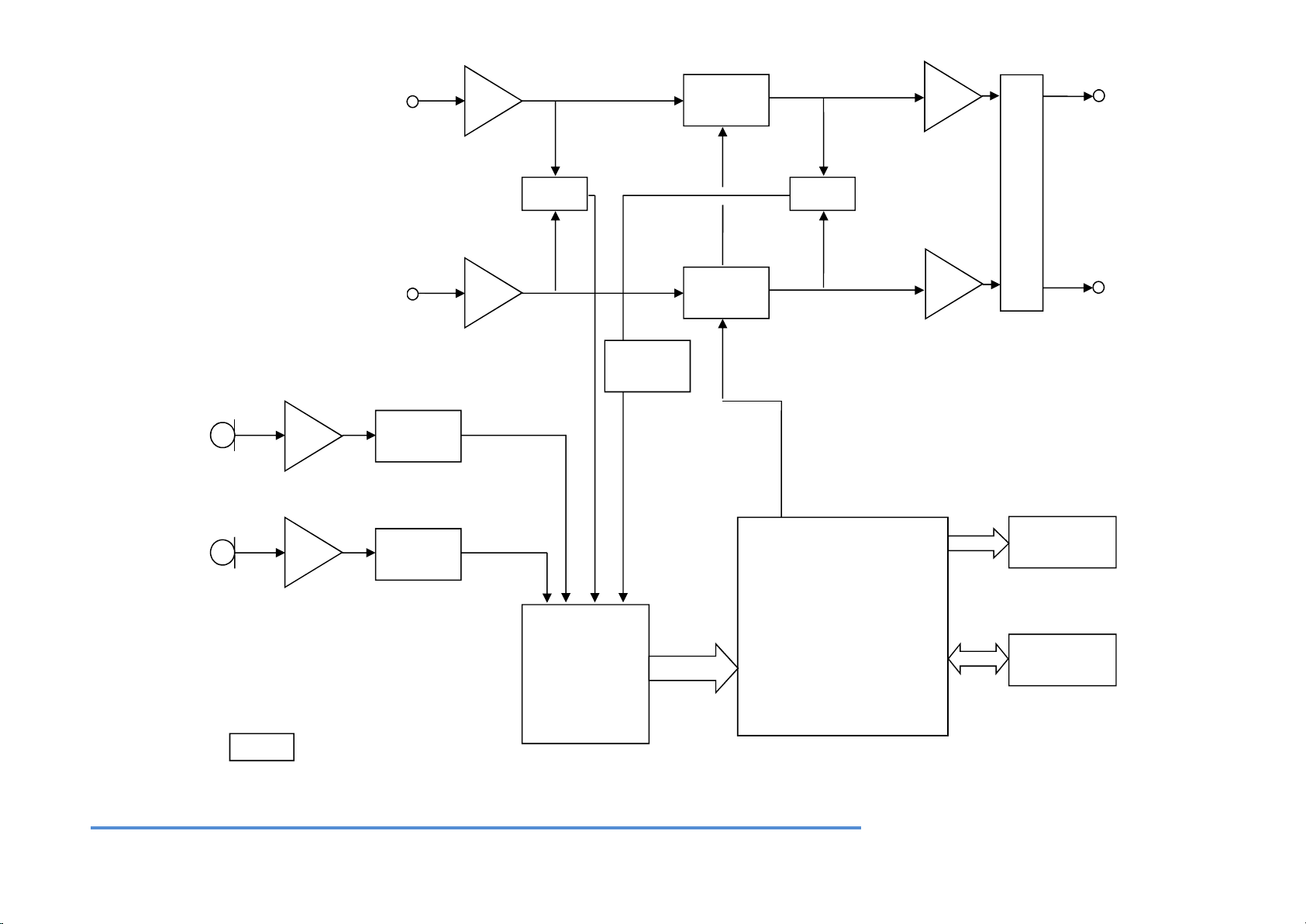
“C” “A”
LEFT LINE INPUT
VCA
SUM
SUM
R
E
L
A
Y
S
LEFT
LINE OUT
RIGHT LINE INPUT.
VCA
RIGHT LINE
OUT
FILTER
MIC 1
FILTER
“C” “A” “BASS”
MIC 2
FILTER
BANDS
FILTERS
uC
DISPLAY
COMMS
FIG 1
MRC AUDIO EQLimit
Page 7

DESCRIPTION
4
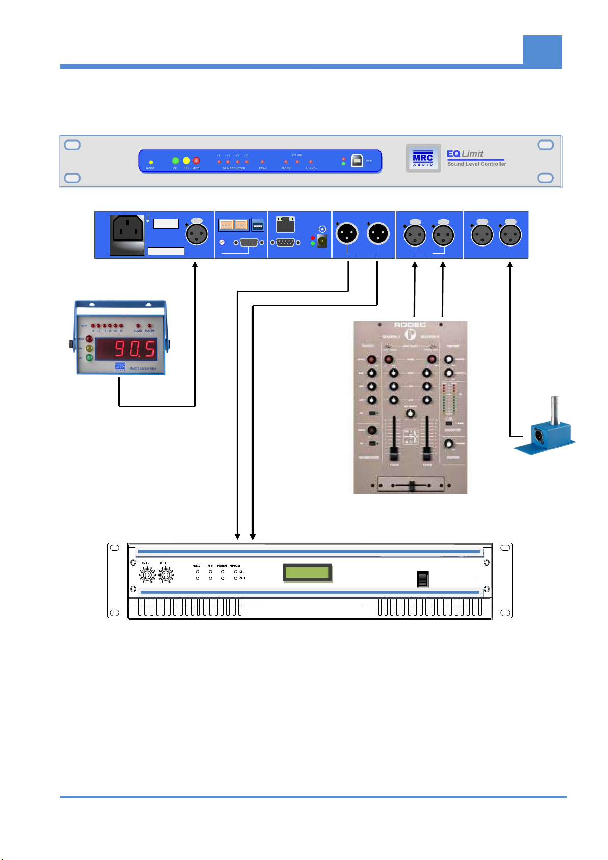
The next text refers to fig.2 that shows the indicators and necessary connexions for a proper
use of EQLimit
1. NOISE – The limiter has an internal pink noise generator that leads to a more
comfortable adjusting of the installation. When clicking on the buttons NOISE or CAL,
the signal of this generator is mixed with the audio inputs. Also, this yellow LED starts
to blink.
2. AUDIO LEVEL – Three LEDs show the state of the sound level: Green shows presence
of normal signal, Yellow shows the audio level is above the permitted maximum, and
Red shows the limiter has shut off sound.
3. LIMITING LEDs – LEDs that show the amount of dynamic attenuation applied o the
input signal and input peak.
4. STATUS LEDs – LEDs that show the states of alarm, off time and special period active.
5. USB – USB connector for a direct connexion to a PC.
6. MAINS INPUT – Normalized IEC power input connector with Earth connection and input
fuse. The protecting fuse must always be substituted by one of the same type T
3.15A/250V. Universal power supply 90 to 250VAC.
7. DISPLAY – Connector for the remote display.
8. LEVEL -- Control of the signal level from external emergency message.
9. AUX – Auxiliary connections to drive an optional relay box to control external equipment
and fire alarm input to activate the priority of an external fire evacuation message or
level reduction.
10. MODEM – RS232 connector for the external optional GPRS modem.
11. LAN – Optional Ethernet connector for an ADSL router.
12. MODEM POWER FEED – Jack connector to feed the optional external GPRS modem,
with selectable 5 or 15Vdc, by means of internal jumper, with LED indication of the
selected voltage.
13. XLR OUT – Output balanced connectors for channels left and right.
14. AUX – Level control for the external fire evacuation message.
15. XLR IN – Input balanced connectors for channels left and right.
16. MIC1 - 2 – Input balanced connectors for main microphone 1 and optional registering
microphone 2.
MRC AUDIO EQLimit
7
Page 8

FUSE
10
5
15
20
-
-
PEAKMUTE
NOISE
-
-
OK
PRE
GAIN REDUCTION
1 2 3
9
SERIAL NO
E172301
FOR SAFETY OPERATION, PLEASE,
REFER TO USER´S MANUAL
6
PUSH
DISPLAY
7
AUX OUTPUT
L R
LEVEL
AUX
8 11 12 13 14 15
OFF TIME
ALARM SPECIAL
4 5
10
LAN
15V
RS 232
5V
DC OUT
-
USB
RL
L
PUSH PUSH
EQ Limit
Sound Level Controller
R
PUSH PUSH
+
OUT
IN
MIC 2
MIC 1
MRC AUDIO EQLimit
Fig . 2
Page 9
POWER
AMPLIFIER
DISPLAY
INSTALLATION
5
PUSH PUSH
IN
EQLimit
Sound Level Controller
PUSH PUSH
MIC 1MIC 2
RS 232
OFF TIME
USB
LAN
DC OUT
+
-
15V
5V
RL RL
OUT
20
-5-15-10-
PRE ALARM SPEC IAL
OK PE AKMUTE
NOISE
SE RIAL NO
E182401
FUSE
FOR SAFETY OPERATION, PLEASE,
REFER TO USER´S MANUAL
DISPL AY
GAIN RED UCTION
LEV EL
AUX OUTPU T
L R
AUX
PUSH
MICRÓFONO
MIXER
FIG. 3
This unit has been carefully packed at the factory inside a specially designed case.
Nevertheless, we recommend you supervise the state of the box and its contents.
Please do keep all the packaging items in case the unit should go back to MRC Audio.
MRC AUDIO EQLimit
9
Page 10

The content of the box is:
EQLimit
MS1 Microphone
Remote display DD1 (optional)
USB cable
Power feed cable
Backplane cover TP2
Microphone cable CM10
NOTICE: The graphics included represent the equipment with all its accessories. Some may
be optional. If you need an accessory, include it in your order.
5.1.- Connections
Input and output connexions are made by means of XLR-3 connectors. The connection
pin out follows the international standard: Pin 1 is signal ground, Pin 2 (+) is non-inverted
and pin 3 (-) is inverted. Please be sure to follow the same scheme in both channels to
avoid phase cancellation problems.
Connect input and output audio signals (13 and 14) in such a way that the limiter is
connected just before the crossover or power amplifiers if there is no crossover.
Either balanced or unbalanced lines are used, be sure to follow the same pin out at both
channels to avoid phase cancellations.
Connect the microphone(s) to the MIC1 and MIC2 (optional) (15). Position the
microphone in a centred position with respect to the speakers in order to measure both
audio channels. Try to position the microphone as near as possible to where the
authorities would control the sound level from music, not the audience.
Optionally connect the remote display by means of its cable to the connector DISPLAY
(7). The remote display cable is 5 meters long.
Finally, connect the mains cable supplied with the unit to the mains input and the unit
will switch on. Do always connect the earth connection for your personal security.
Test for correct sound. If the remote display is installed verify that the metering varies
according to the sound level in the house. If display Und (35dB or less) maybe the cable
is connected in wrong way and sounds mute.
MRC AUDIO EQLimit
10
Page 11
5.2.- SCL Software installation
Download from www.mrcaudio.com the executable SCL v2.xx. Run this executable in your
PC and follow instructions on screen. Once installed the icon appears on your desktop.
Double clicking this icon runs the software for EQLimit setup and control. Always open this
program as administrator
Before attempting to adjust the limiter, you must request to MRC Audio (info@mrcaudio.com)
an installer’s license and register this license in the User Data window. Fill up all user data and
register your license. When activated, check the “Remember in this PC” tick.
This license identifies the installer every time he makes a configuration change in the limiter. If
you do not have a valid license the limiter works in Demo mode, where no changes to the
limiter’s configuration are possible.
5.3.- Limiter’s password
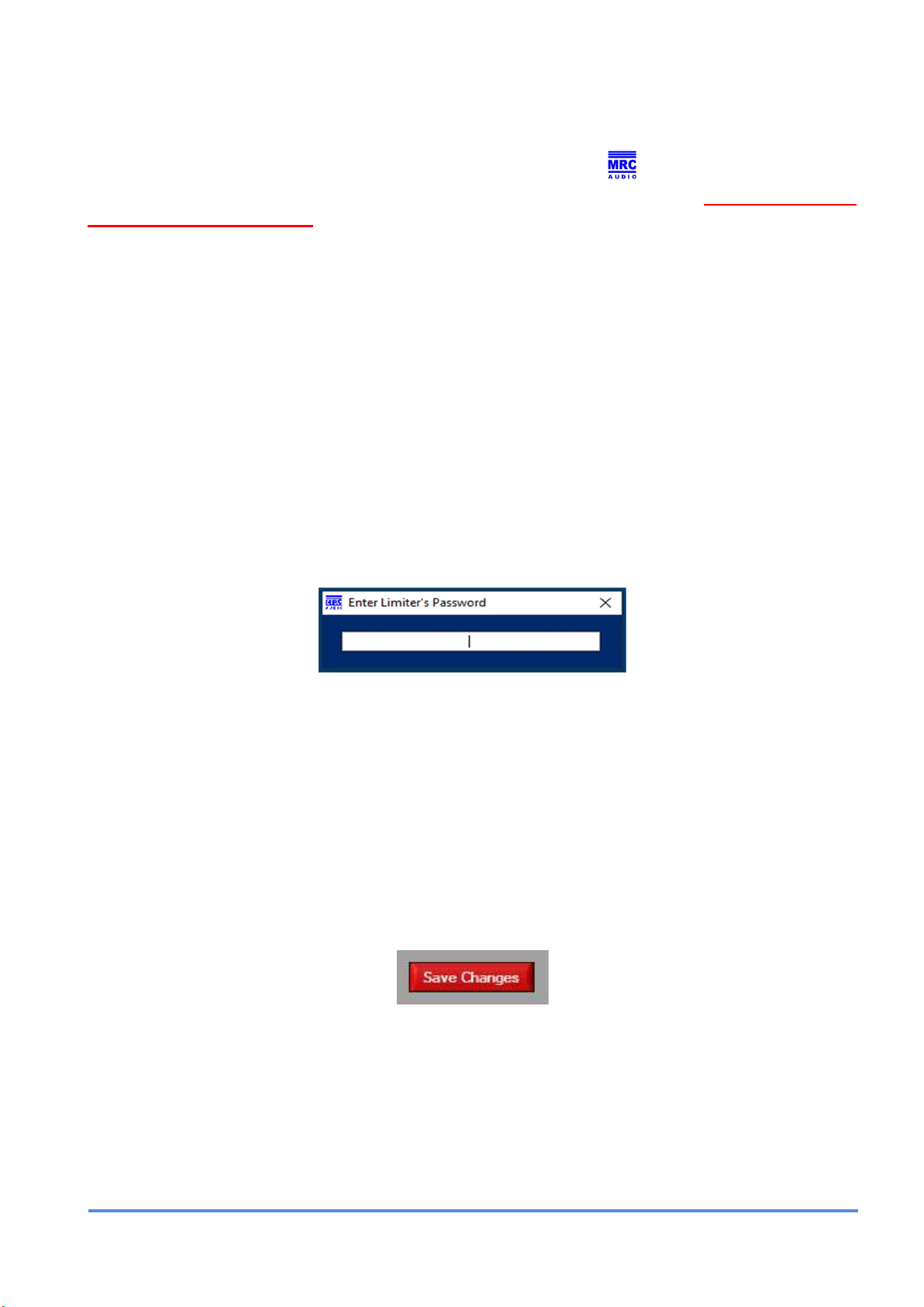
Besides needing a user’s license for the SCL software, every time you attempt to change any
configuration parameter in the limiter, the limiter will request a password to permit changes.
For this purpose an emerging window will appear to input the password:
Enter the limiter’s password. The default password for all limiters is 1234. This password can
be changed by the user as described further on.
Once the password has been entered once, it will not be requested for further changes unless
a period of at least 5 minutes exists between two successive changes, or if the software is
restarted.
If a valid password is entered, the emerging window disappears and the changes are made in
temporary volatile memory. If the limiter is switched off, these changes are lost. This is why a
“Save Changes” button appears at the bottom left corner each time changes are made:
Clicking on this button makes the changes permanent and stored into non-volatile memory and
the button disappears until new changes are made.
Also, if the screen is exited and changes have not been saved, an emerging window appears
inviting to save changes:
MRC AUDIO EQLimit
11
Page 12

On this emerging window Yes saves changes, No continues exiting the window without
saving changes and CANCEL cancels exiting and redirects back to the actual screen.
The save changes process is repeated each time any configuration changes are made
into the limiter, but also, it is possible to save changes only once after making all the
changes wanted.
5.4 Master Password
If the user forgets the password to configure the limiter, MRC Audio can provide a master
password valid for only that limiter, as a function of its serial number, and valid only once.
Introducing a master password is registered in the limiter’s non-volatile memory as an event,
together with the date and time as all other events, and together with the authorised user that
has entered the master password.
NOTICE: Each MRC Audio EQLimit has up to ten master passwords. Each time one is used it will not work
ever again. If all ten master passwords are used and still the user keeps on forgetting the password, the limiter
will have to be serviced at MRC Audio to restore ten new master passwords.
MRC AUDIO EQLimit
12
Page 13

C
ONFIGURING PANELS
6
To open the program, always activate the "Run this program as administrator" box in Properties
and Compatibility tab of icon .
Clicking on this icon, created on the desktop at software installation time, the initial window
appears where you can choose the user´s language through its corresponding flag.
Once clicked on the language flag, the rest of buttons change to the language chosen.
MRC AUDIO EQLimit
13
Page 14
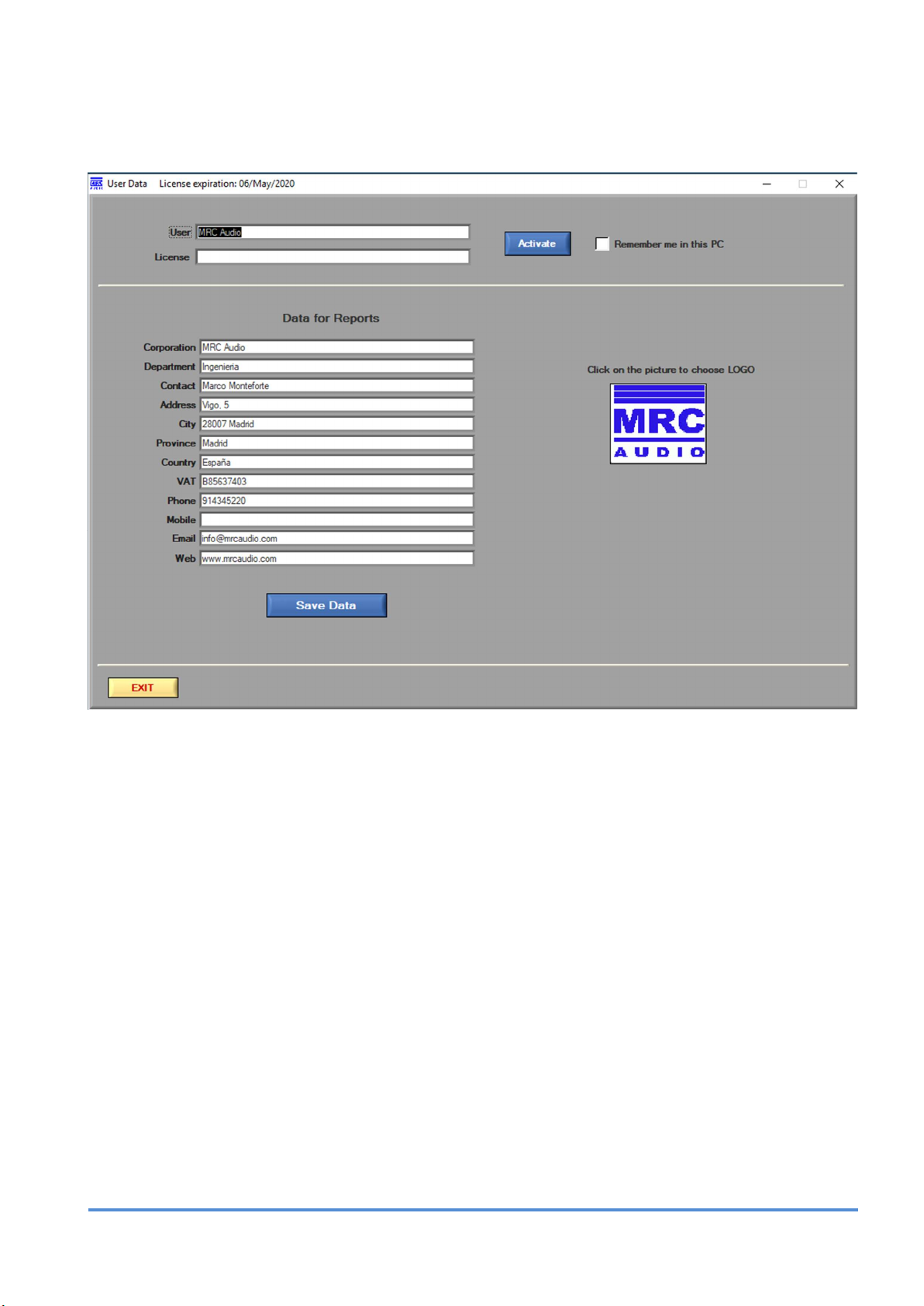
USER’S DATA – This button takes us to the next screen, where it is possible to fill in the
software’s user data and the license provided by the manufacturer.
In the User field, fill in exactly the user name provided by the manufacturer. This name will
identify you when accessing any EQLimit.
In the License field type in the license number provided by MRC Audio; this field is case
sensitive.
Please fill in all fields, including the logo of your company, as this data will appear at the
headings of the reports.
Click on the Save Data button and then on the Activate button and the software will be ready
to use.
If the Remember me in this PC box is checked, the application remembers your license
number not needing to type it in each time the application is launched. But remember that
anybody using this PC will also not need to type in any license number at launching and
therefore anybody can make changes to limiters in your name.
EXIT goes back to the initial window.
MRC AUDIO EQLimit
14
Page 15
Again, at the initial window the rest of the buttons are:
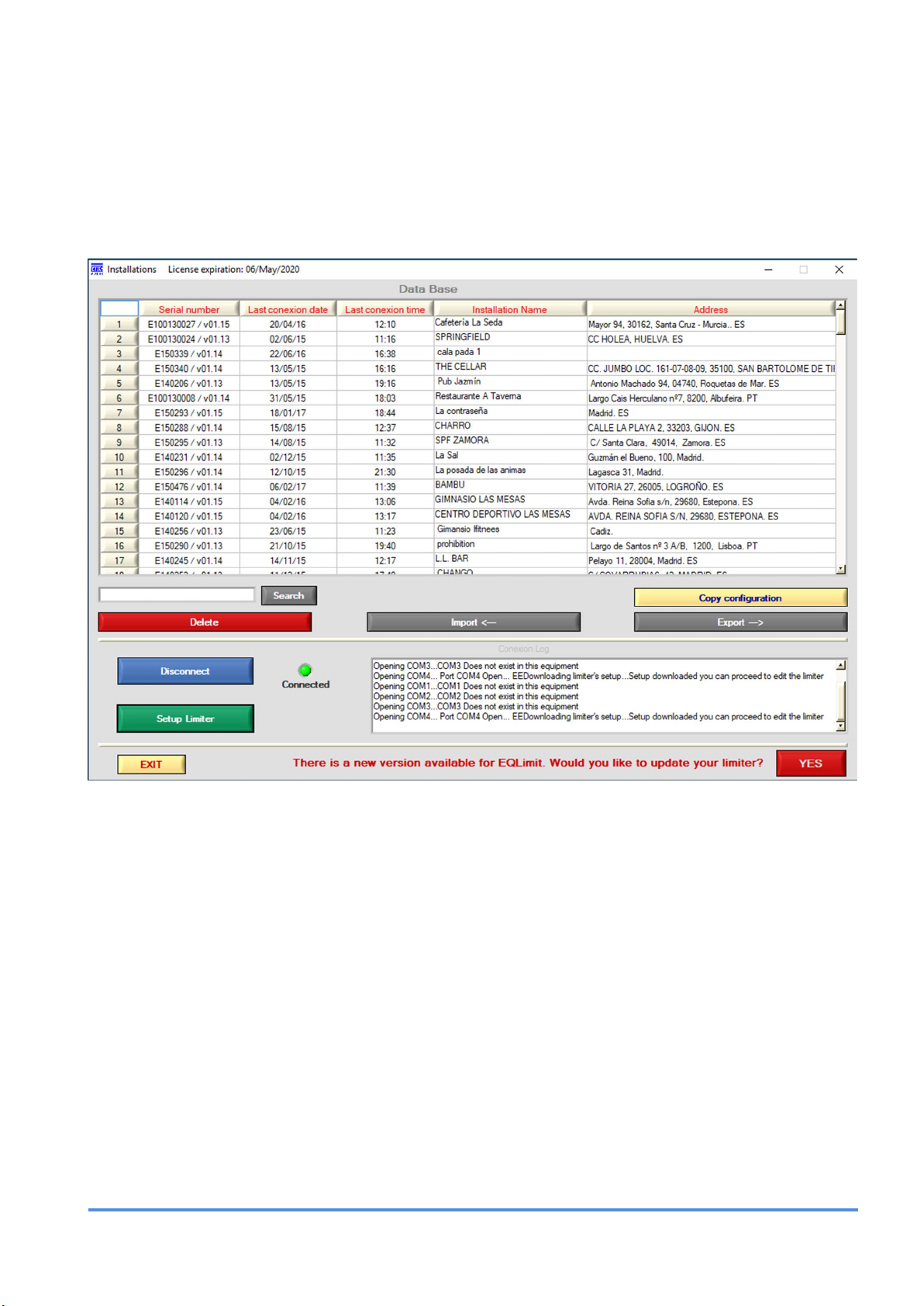
INSTALLATIONS – Opens the window with the list of installations kept in the data base and
with the required buttons to connect to an EQLimit.
Any data base installation can be opened in read only mode clicking on the corresponding
numbered button in the left column.
Search: Finding installations is possible by typing the name or part of the name or any
identifying word into the Search box and clicking on the Search button.
Delete: Installations can be erased by clicking on the Delete Button; the button changes to
Select Installations. Cancel/Continue and colour blue. Once the delete button changes, click
on one or more installations by means of their left hand numbered buttons. Each time a button
is clicked it changes to blue colour. Once all installations wanted to erase have their left hand
numbered button coloured blue, click on the Click here to delete button, now colour yellow,
to erase them permanently. This action is not reversible, therefore be sure you have chosen
the wanted installations before deleting.
If you do not want to delete any or all installations, unselect them by clicking again on its blue
button that will change back to its normal grey colour. If all installations are deselected, the
Click here to delete button changes again into Select Installations. Cancel/Continue and
colour blue. Click on the button to go back to the initial state without deleting anything.
NOTE: on top of the numbered left-hand buttons there is a button with an asterisk; clicking on
this button alternatively selects/deselects all installations.
MRC AUDIO EQLimit
15
Page 16

Download to limiter: It is possible to download the entire configuration from a database limiter
into the actually connected limiter. Obviously, it is mandatory to be connected to an EQLimit
before proceeding with this action.
Click on the yellow Download to limiter button. This action will change the installations’ lefthand numbered button into yellow colour. Click on the chosen database installation’s left-hand
numbered yellow button and the entire configuration of that database limiter will start
downloading into the connected limiter.
Be patient, this action may take some seconds. Wait for the download to complete; the USB
red LED, on the connected limiter, blinks as data is transferred while downloading, and stops
blinking when the action is finished.
Export ---> It is also possible to export the entire configuration of one or more database limiters
to a file within the PC with the extension .mef in order to share database installations with other
PCs, or simply as a back-up method.
Like with the delete button, click on the Export ---> button that changes to blue, choose the
wanted installations, again the asterisk button alternatively selects/deselects all installations,
and click again on the now Click here to export and colour green, to export the installations.
This will open an OS window that permits choosing the name and location of the export file.
Import <--- This button imports into the SCL database any exported .mef files. Clicking on this
button changes it into Importing… and colour red and opens an OS window to look inside the
PC for the .mef file that is to be imported. Once chosen the file to be imported with the OS
window, the application adds the contents of the .mef file to the SCL database, the OS window
disappears and the import button goes back to its initial state.
The connect button and log window are explained further on.
The EXIT button goes back to the initial window.
Back at the Initial window:
USER’S MANUAL – This button opens a .pdf file with this user’s manual in the language
chosen for the application.
BACKUP – Creates a backup file (*.mrb) with the entire current database to reinstall in a
different PC or for after a total formatting of the disk.
Clicking on this button an emerging window appears inviting to create or to restore a database:
Click on any of both, an OS window appears to select the name and location of the file to create
or to find the file to restore.
MRC AUDIO EQLimit
16
Page 17

PROGRAMMING
7
After connecting the corresponding USB cable between the PC and the limiter, in the
Installations window, click on the Connect button and wait while the SCL finds the limiter.
The log window shows the connecting process.
Once the limiter is connected to the control software, if the firmware version of the equipment
is earlier than the one you are using in the SCL, a flashing warning appears offering the
possibility of updating your equipment.
If you do not want to update at this time, you can press the "Edit Limiter" button and continue
normally with the current version.
If you choose to update, it gives you the opportunity to confirm that update or postpone it to
another time.
If you choose the Later option, you usually continue with the connection process. If you confirm
the update by pressing Yes, the update process begins.
NOTICE: the update action is of your entire responsibility. It takes a time to transfer the
update file to the limiter, in this time the limiter must not be disconnected from the PC.
If the action fails for any reason, the limiter will have to go back to the manufacturer in
order to burn the entire firmware into the limiter’s microprocessor.
MRC AUDIO EQLimit
17
Page 18

When you connect to an EQLimit with the corresponding firmware version, this other sign
appears to confirm the connection or cancel it.
To finalize the connecting process, click on the OK button on the emerging window.
The Disconnected red LED changes to Connected and colour green and he Connect button
changes to Disconnect as clicking on this button again disconnects the limiter from the SCL
application.
A button Edit Limiter appears under the Disconnect button. This button is initially dimmed
while the limiter’s configuration data is downloaded to the PC. Also, the log window notifies
that the configuration is being downloaded:
Once uploaded the Edit Limiter button un-dims and the log window notifies:
Now the limiter’s configuration parameters can be edited, as described further on.
EDIT LIMITER CONFIGURATION TABS
Clicking on the Edit Limiter button the configuration window appears. It is a group of sub
windows each headed by a tab.
The application header constantly shows the serial number of the equipment, the installed
firmware version, date, time and expiration date of the license.
MRC AUDIO EQLimit
18
Page 19

7.1 INSTALLATION FILE
This tab opens the Windows that shows all the information about the installation. Name, contact
data, address, installer’s data, installed equipment, observations and attached files to ease the
consulting of files related to the installation.
Beyond version 2.19 it is possible to make a domain reservation of the installer to its client,
simply by checking the box. This applies a grace period of 3 months. If by that time the box
has not been deactivated, the device will stop working. Five days before expiring, the
illuminated logo of MRC Audio flashes with intensity to warn of the end of the reservation
period. When the date arrives, it will flash every second and interrupt the sound. Only the
installer will be able to restore the device to normal operation.
We can also apply a renewal date of the SCL software license that will always appear at the
top of the SCL panel, to know when we must renew it.
Once filled in all the data a configuration report can be generated clicking on the Generate
Configuration Report button. This will open an emerging window to choose among the
possible report formats: Word or PDF.
MRC AUDIO EQLimit
19
Page 20

7.2 LIMITER ADJUST
The MRC Audio EQLimit limiter is factory adjusted for its immediate use, with the microphone
1 signal as the controlling signal for limitation and with its standard parameters. Only the
maximum sound level needs to be adjusted.
If we need to change any of the default parameters, we can do so in the Limiter Adjust window:
Sessions – Adjusts the minimum sound level and the time that level needs to be surpassed to
consider the beginning or ending of a working session. The beginning and ending of the
working sessions are registered in the events memory together with their date and time as all
events.
Leq – Adjusts the integration time for the Leq parameter.
Registry – Adjusts the minimum level to record in the events memory and the time interval
between two successive level events to be recorded.
Alarm Configuration – Determines the alarm level (condition) and time persistence for the
alarm condition for each type of alarm; it is also possible to choose if the alarms will be recorded
in the events memory, if the alarm should cause a mute and if the alarm should activate the
limiter’s auxiliary output pin. Only the Microphone alarm has no level or persistence time adjust
as the microphone alarm arises immediately when the microphone is disconnected from the
limiter.
MRC AUDIO EQLimit
20
Page 21

Auxiliary output pins can be activated and configured to turn on or off auxiliary external
equipment activated by an alarm or pre-alarm (Request schematics for proper use of the AUX
CONNECTOR).
The EQLimit limiter has capacity to register three types of alarms of the proper sound system,
plus an external alarm described in the Preferences tab description.
Microphone Alarm. Arises when the sensing microphone is disconnected from its
corresponding input connector.
SPL Alarm. Arises when the sound level sensed by any of the two microphones
surpasses the limiting level plus a margin, during a persistence time.
Efficiency Alarm. Or manipulation alarm, arises when the microphone level is under
the Line Out level in a quantity greater than the margin condition, during the persistence
time. This alarm is useful only if a calibration of the installation is performed; because
the calibration of the sound system is performed only with microphone 1, it is possible
to configure this alarm only for microphone 1.
If Microphone 2 is configured not to be active in the Preference tab, its corresponding
configuration windows and boxes do not appear:
The adjustable parameters for each type of alarm are:
- Seconds: the persistence time in seconds to consider an alarm condition.
- Margin: the sound level margin with respect to the limiting level in the SPL alarm or with
respect to the Line Out level in the Efi alarm, which must be surpassed in the SPL alarm
or under passed in the Efi alarm to start counting the persistence time.
- Record: if checked the alarm is recorded in the events memory.
- Mute: if checked the corresponding alarm causes a mute in the sound system during
the time typed into the Mute time box.
- Output Pin: if checked the EQlimit limiter activates a pin in the AUX connector located
at the back panel of the limiter. This pin is a two state output: 5 volts or 0 volts. And the
active level either 5 volts or 0 volts can be chosen with the Output pin Active level
switch. This is: if the switch is at its Off position, the output pin at the AUX connector will
normally be at the 5 volts level; when the alarm occurs, the level at the AUX output pin
changes to 0 volts. On the contrary, if the switch is at its On position, the AUX output
pin is normally at the 0 volts level and changes to 5 volts when the alarm occurs.
Adjust date & time – Click on the PC button to read the date and time from the PC, and click
on the Adjust button to transfer this date and time to the limiter. Alternatively, the date and
time can be adjusted manually before clicking on the Adjust button.
If daylight saving leap hour is desired, check the Daylight saving box and adjust the date and
hour of the hour change, before clicking on the Adjust button.
Special Periods – The EQLimit limiter has the capacity to configure up to 10 special periods
in which the maximum permitted level and timetable can be different to the normal settings.
MRC AUDIO EQLimit
21
Page 22

In each of these ten rows T1 to T10, this is for each special period, a beginning date, ending
date, beginning time, ending time and permitted sound level have to be configured.
To configure a special period, click on the Special Date, From column, day box; a list appears
with the days 1 to 31. Click on the desired day. In the same way choose the beginning month
in the Special Date, From column, month box. The ending date is configured in the same way
using the Special Date, To day and month boxes. Because it is not possible to go back in time,
when the From boxes are filled in, the To boxes change accordingly. Also not existing dates
are forbidden, like February 29th if it is not a leap year or April 31st for example. If chosen, the
boxes change automatically to the previous permitted day.
In the same way configure the beginning minutes and hours and ending minutes and hours in
the Special Timetable, From and To columns.
Also configure the permitted maximum level during that special period in the SPLmax column.
The EQLimit limiter accepts time intervals starting one day and ending the next day, as this is
the normal working intervals in clubs. Therefore, if the TO time is earlier than the FROM time,
the limiter assumes that the TO time is a time in the next day.
The Act. and Reg. boxes mean Active and Register respectively. The Act. box must be
checked to make the special period active, and the Reg. box must be checked if you want to
register sound levels and alarms in the events memory during the special period.
In the example picture above, a single special period has been configured: T1. In such way,
from July 6th to July 14th the limiting level is 100dB from 10:00 in the morning to 6:00 in the
morning of the next day. The period is active and sound levels and alarms will be registered in
the events memory.
This functionality is very useful also to add different time frames to each day within the specified
time period.
MRC AUDIO EQLimit
22
Page 23

7.3 LEVELS AND TIMETABLE
In this tab we can adjust the levels and operating time schedules for the main audio output L
and R.
If the Without weekly timetable box is checked, only one limiting level will be configured for
all the week days for 24 hours.
In the Max. SPL box type the required limiting level. Click in the box, delete the actual value
and type in with the keyboard the new value in dB and with a maximum of one decimal. For
example, 90.5 dB:
Alternatively, the number in this box can be changed by means of the up and down arrows at
the left of the box; each click on these arrows will make a change of 0.1 dB.
If the Without weekly timetable box is not checked, up to 3 different time periods can be
configured for each day of the week, with their corresponding limiting level, plus the session
ending time. The green horizontal bar at the top changes to a bar with different colours along
its width. The bar together with the Monday to Sunday buttons make a linear graph that shows
the distribution of the timetables along the week:
It is also possible to combine these 3 timeslots with the programming of special periods to
achieve the desired level variation throughout the day in a selected period of days.
MRC AUDIO EQLimit
23
Page 24

The different colours of the bar show the 3 possible day time periods. Green is the first period
of the day, yellow is the second, orange is the third and red is the time between the ending of
a working session and the beginning of the next working session, time in which the limiter
mutes its outputs.
EQLimit permits to overlap days when configuring daily time tables as their sessions start one
day and finishing it the next day.
To change the timetable of a day you can click on that day’s button at the linear strip, or
navigate from day to day with the Previous day and Next day buttons.
The examples figure above shows a time table for Monday as follows:
From 9:00 in the morning to 16:00 in the afternoon the permitted level is 80.0 dB.
From 16:00 in the afternoon to 22:00 in the night still the permitted level is 90.0 dB.
From 22:00 in the night to 5:00 in the next day’s morning the permitted level is 85.0 dB
At 5:00 in the morning Tuesday, the limiter mutes its outputs.
It is possible to type in one single day and copy that input to the rest of the days of the week
or to the days of the week you choose. This is done by means of the day tick boxes and the
Copy to: green button.
MRC AUDIO EQLimit
24
Page 25
Ticking the All box will select/deselect all the days alternatively.
The end of the musical session can be programmed to attenuate the music progressively by
means of a time/dB slope; the progressive attenuation starts the amount of minutes set in the
“minutes” box, before the configured ending time. It will attenuate the amount of dB entered in
the “Ramp” box per minute. Therefore, the slope is decided by the user, such that not
necessarily the end of the slope is the total attenuation of the music; in this case, once reached
the programmed ending time, the limiter abruptly attenuates the music whatever the point of
the slope is reached.
In case you want to adjust only two bands or a single band for a specific day, just write the
same level of limitation in the different time slots that you want to unify. If the same level is
programmed in the three bands, that day has a single time slot, limited in time by the start and
end times.
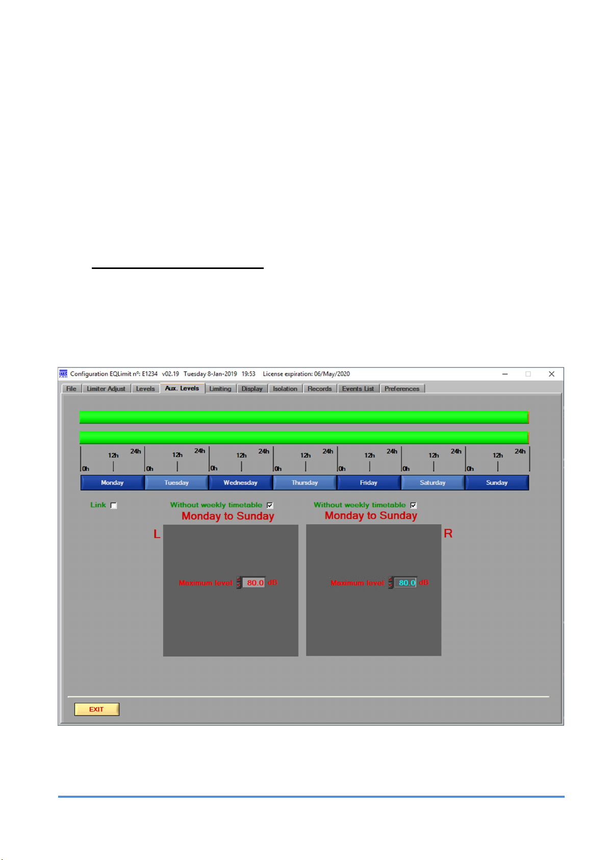
7.3.1 AUX LEVEL AND TIMETABLE
Beyond v2.19, it is possible to incorporate an auxiliary output option that depends on the main
audio output but that may have different levels and working hours.
The adjustment is made in the same way as described above for the main output.
Please, contact us when buying the auxiliary sound output option.
MRC AUDIO EQLimit
25
Page 26
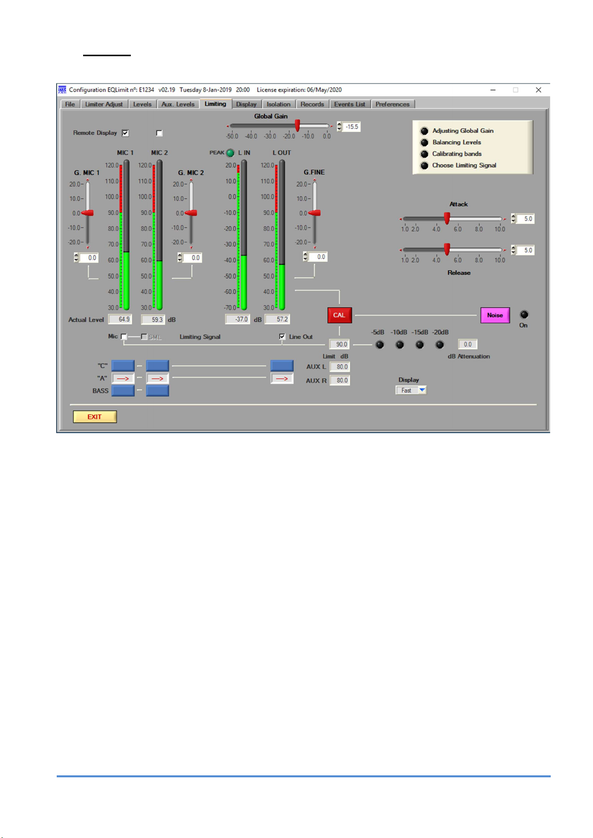
7.4 LIMITER
In this window, we can adjust:
Global gain, gain for microphone 1, gain for microphone 2 and fine gain for Line Out.
Also choose a filter for the measure of both microphones and Line Out (A, C or
BASS<300Hz).
Adjust the Attack and Release times for the dynamic control of the limiter.
Switch on the pink noise generator.
Calibrate automatically to equal the Mic 1 and Line Out levels clicking on the CAL button.
This process is guided by 4 LEDs and emerging advice windows.
Select the control signal for limitation between MIC1 or L Out
The permitted maximum level is shown in the Limit dB box, and the applied attenuation is
shown by the 4 level LEDs and the numeric box to the right.
The vertical level bars show the real-time levels for the different channels and these can
be seen with a fast or slow integration, chosen by the Display box.
MRC AUDIO EQLimit
26
Page 27

7.4.1 Calibration process
Before executing the calibration process it is necessary to configure the global limiting level as
described in previous chapters. It is also necessary that the sound system, the limiter and its
sensing microphone (must be microphone 1 for calibration), are installed at their final locations.
The first step is to verify that the microphone level shown at the SCL application is the same
as the level shown by a certified sound level meter, to compensate for the variations introduced
by different factors like the distance to the speakers, the sensing microphone’s proximity to the
ceiling or walls, the effects of the sensing microphone’s protecting box, etc.
To do so, first select the measuring filter and the measure mode to be equal at both limiter and
sound meter; click on the Noise pink button to switch on the pink noise generator and have
pink noise sound in the house, and adjust the microphone 1 gain, G. MIC 1 slider, until both
limiter and sound meter measure the same level. Once adjusted microphone 1’s gain, click on
the Noise button again to switch off the noise generator.
In the G. MIC 1 slider control, the 0 point is adjusted at factory. This control can be adjusted
my moving the red slider with the mouse, by clicking on the top and/or bottom small red arrows
to obtain a 0.1dB increment per click, by typing a numeric value directly into the numeric box
at the bottom or by clicking on the numeric box up and own arrows to also obtain 0.1dB
increments.
The same adjustment can be done with microphone 2 if present.
Once the limiter’s sensing microphone measures the same as the sound level meter, you can
proceed to calibrate the whole sound system. During this process, pink noise will be emitted
through the sound system; avoid emitting any other sound in the house, be silent during this
process. The process is automatic and is guided by the top left corner LEDs and different
emerging windows; follow instructions:
At the Display box select slow.
Click on the CAL button. An emerging window appears inviting to fade out music and
turning the amplifiers to maximum power.
Click on the OK button. The limiter automatically turns its global gain to minimum,
activates pink noise and switches to “A” filters.
The Adjusting Global Gain LED starts to flash and the limiter automatically increases
the noise level until the sensing microphone reaches the limiting level.
Once reached, the Adjusting Global Gain LED stops flashing and the Balancing
Levels LED starts to flash. At this time the limiter is automatically adjusting the Line out
gain to match the microphone 1 level.
Once matched, the Balancing Levels LED stops flashing and the Calibrating Bands
LED starts flashing. The limiter registers the frequency band levels for later comparison,
taking around 30 seconds.
Choose Limiting Signal LED starts flashing. At this time choose the limiting signal:
microphone 1, SML or Line Out, by clicking on either the Limiting Signal: MIC1,SML
box or L.OUT box, located just underneath the meter bars.
Once chosen the limiting signal, all LEDs stop flashing and the pink noise is switched
off.
MRC AUDIO EQLimit
27
Page 28

This automatic adjustment is an approximation due to spectral differences between both
signals compared: microphone and line; therefore, a manual fine adjustment of the Line Out
gain may be needed. Do adjust the Line G.FINE slider control if necessary.
This calibration permits the limiter to limit through either microphone 1 signal or Line Out signal.
It also permits to detect manipulation on the sensing microphone 1, and generate the
corresponding Efi alarm if activated at the Limiter Adjust tab as described in previous
chapters.
The difference between microphone 1’s level and the Line Out level is due to either changing
the sensing microphone’s location, covering it with sound isolating material or because parallel
sound systems, out of the control of the limiter, are installed in the house.
Also this calibration adjusts the limiter’s global gain only 8 dB over the working limit, adjusting
the total power of the installation to the real working level. This means that the limiter can work
at lower attenuation levels, what results in a better sound quality.
Finally, during this calibration process, the limiter registers a spectral “stamp” measured by the
microphone 1 that permits comparing by emitting pink noise again at any future time. This
comparison permits to know if the house acoustical conditions have been modified.
This comparison can be done automatically, every time the limiter is switched on, if the
Automatic Band Calibration button, at the Preferences tab, is in its ON position; see the
Preferences tab description further on. If automatic, the band comparison is registered in the
events memory each time the limiter is switched on and the comparison is automatically
launched.
Or this comparison can be done manually whenever the installer or authorities require so. See
Isolation tab description further on.
MRC AUDIO EQLimit
28
Page 29

7.5 DISPLAY
This window reproduces the limiter’s external remote display, in a bigger size to permit a better
reading of the sound level at a distance.
Like the remote display, it shows the attenuation level by means of a bar of LEDs and signalises
alarms and/or excessive input level by means of dedicate LEDs
By three big leds, show the activity of sound signal inside the unit:
Green - Input signal is present at connectors and its level is under the max authorised level.
Yellow - The unit is controlling the audio signal amplitude.
Red - The unit mutes de audio output.
MRC AUDIO EQLimit
29
Page 30

7.6 ISOLATION
The limiter is factory adjusted to work with global limiting through “A” filter. If you wish to use a
control signal that responds to the acoustical isolation, adjust in this window the previously
measured isolation and immision levels, so that the limiter responds to a limiting level per
frequency band.
At the real time measuring vertical bars, when a frequency band’s level surpasses its limiting
level, the bar changes from green to red colour; therefore, we can perceive at a glance a real
time spectral distribution of the sound
It is possible to choose between MIC1 or Line Out signals for limiting, and the spectral limiting
becomes active when switching the Band Limiting ON/OFF button to ON.
The global MIC1 and Line Out real time levels are also show at the right of this window in order
to have a more global view of the signals involved in limiting.
The working levels of each band can be determined manually or applying the normalised
isolation STC and inmision NC curves, or applying global values that are distributed equally
through all the bands.
Once the limiting values per band are adjusted, an equivalent limiting global value is calculated
and shown; it is possible to transfer this value to the Levels tab in order to fill in the global
value and the timetable values.
In the lower part, the calculated values of immission in the neighbor are shown in real time.
MRC AUDIO EQLimit
30
Page 31

The band limitation is subordinate to the global limitation; EQLimit limits per the more
restrictive of the two: if the maximum level is surpassed in any of the bands, the limiter will start
limiting. But if no band reaches its limit but the global sum their level reaches the global limit,
the limiter also starts to limit.
This window has vertical level measuring bars for the normalized bands centre frequency. The
seven lower frequencies are centred in 1/3 octave bands and the five higher frequency bands
in octave bands, having more precision at the lower frequencies because these are more
problematic from the Isolation point of view.
In order to control the limitation, you can choose all 1/3 octave filters or only the eighth octave
band filters with the selection boxes and we can also activate or not each band to be included
in the measurement of the control signal.
To the left of each bar there is numbered scale and a two colour strip: green the lower part and
red the upper part of the strip. The point where the strip changes colour is the limiting level for
that band. Those bands that surpass the limit change from green to red as seen in the previous
figure.
In the numeric box, underneath the bars, the real time level per band is shown with 0.1dB
precision.
Below the band bars there is a matrix of 3 rows x 12 columns numerical boxes, for the
adjustment of the band limits, per two different data groups:
The lower row is the inmision group of data; the middle row is the isolation group of data. The
upper row is the sum of the two and is the resulting limiting value.
The immision is the maximum sound level that can be induced to the neighbour houses. This
level is either global or per bands, depends on local regulations.
The Isolation is the amount of sound isolation existing between the house and the worst case
neighbour.
The upper line is not editable because it is the resulting limiting level calculated by the sum of
inmision and isolation.
To the right of the Lim row, the upper row, there is a numerical box where you can set the max
allowed global limit.
To the right of the isolation and inmision rows, there is a group of boxes an buttons that aid in
the fulfilment of the column boxes; either with a “Global” value, distributed equally throughout
the bands or with a value resulting from the choice of a normalized “STC” or “NC” curve, for
isolation and for immision respectively. Or even manually, you can edit he desired value.
MRC AUDIO EQLimit
31
Page 32

The latest pulsed button, either Global or STC and either Global or NC, will change to blue
colour, indicating if the levels in the matrix’s boxes correspond to a global value or to a
normalized value.
After adjusting of the limiting levels per bands we get a resulting global limiting level value that
might not be the same as the value adjusted previously in the Level tab. If we want to transfer
this new value to the timetable and global boxes in the Level tab, write the new max level in
Max window and just click on the Trans button. Doing so, it means that the global limiting is
subordinate to the spectral limiting.
If the resulting band global limiting value is not transferred to the timetable and global limiting
boxes, the spectral limiting will remain subordinate to the global limiting; therefore after doing
all adjustments and after 3 minutes without typing any data into the matrix, the limiting levels
per band will be automatically adjusted to match the global limiting value typed in the Level
tab, proportionally so that the spectral relations are not lost.
It is possible to see the real time frequency spectrum for microphone 1 or Line Out. To the
left of the bars there are two buttons that select which of the two to show on the bars. This also
selects which of the two will be used as the limiting signal. The band limiting is activated by
turning ON the ON/OFF button just underneath.
The real time measure can be seen with a fast or a slow integration time.
To the right of these 12 bars that correspond to the filters, there are two other bars that measure
the global level for microphone 1 and Line Out:
With both groups of bands, we have both options in a single window and all the information,
global and per bands, at a glance.
MRC AUDIO EQLimit
32
Page 33

As it was seen in (7.4.1) at the end of the calibration process, the equipment records a trace
of the spectrum measured by the microphone at that moment. We can check this spectrum at
any time by pressing the button "Footprint of Bands" and generating pink noise, see and
register the differences that could exist between the original static spectrum (in the left scale
white / blue of each band) and the current one (white bar). The limiter can also perform this
checking automatically every time it is turned on if we program it in "Preferences".
MRC AUDIO EQLimit
33
Page 34

7.7 RECORDS
This window is a reminder of the changes made to the configuration of the limiter. All
configuration changes are registered in non volatile memory inside the limiter and this record
can be recovered from this utility.
This window also shows total counters for the alarms and sessions that have occurred in the
past of the limiter.
It is possible to generate a report of the desired period in pdf.
MRC AUDIO EQLimit
34
Page 35

7.8 EVENTS LIST
This window provides with a summary of the activity of the installation, that is stored in the nonvolatile events memory of the limiter. Data can be downloaded from the limiter to the SCL
application filtering by dates or time periods.
Once downloaded, the events are listed and the creation of graphics is then possible.
It is also possible to create reports in PDF, Excel, Word or XML formats to be printed or email.
In the case of XML, the report is AES encrypted following a protocol from the City Council of
Málaga for the authorized installers to send their reports to the authorities in that only
municipality.
NOTICE: In order to be able to generate the report in these formats, it is necessary to have installed Microsoft
Word®, Excel or Adobe Reader
MRC AUDIO EQLimit
35
Page 36

The registered records are the next:
- Sound measurement data, this is the sound levels, with adjustable minimum level to
register and register frequency.
- The beginning and ending of working sessions. The start and end of a working session
conditions are adjustable.
- Microphone, level and efficiency alarms.
- External alarms if these are connected to the corresponding input pin in the auxiliary
AUX connector located at the back of the unit, as described in section 7.10 Preferences
of this manual.
- The moment of switching off or on of the unit.
- The moment when a change in configuration is made; it registers the name of the
authorized installer that makes the changes.
- Master password access is registered, together with the name of the authorized installer
that has used it.
- The moment when a download of events is made.
- When is connected to Internet
- When disconnect from Internet
- When compare levels in each band to detect any misalignment
Sound Level Measurement Data:
EQLimit has the capacity to measure and register the next sound parameters:
- Instantaneous SPL of microphone 1 (Leq 5 seconds).
- Leq with adjustable integration time, for microphone 1.
- Percentile L90 for microphone 1.
- Percentile L10 for microphone 1.
- Instantaneous SPL of microphone 2 (Leq 5 seconds).
- Leq with adjustable integration time, for microphone 2.
- Percentile L90 for microphone 2.
- Percentile L10 for microphone 2.
- Instantaneous level for Line In (Leq 5 seconds).
- Instantaneous level for Line Out (Leq 5 seconds).
- Leq with adjustable integration time for Line Out.
- Maximum permitted level (limiting level) for that moment.
- Attenuation applied by the limiter in that moment.
The sound level measurements are stored in the non-volatile events memory in a periodic
manner with a frequency configured by the user. The minimum level to register is also
configurable. If the instantaneous level of microphone 1 is less than this minimum, none of the
sound parameters will be stored into the events memory even if the period time has elapsed.
All this stored data can be downloaded directly from the limiter via the USB connection; after
downloading this data is kept in a data base in the PC and can be analysed in off line mode
afterwards.
MRC AUDIO EQLimit
36
Page 37

Reading data in CONNECTED mode
The top right corner of this screen is the section for downloading data from the limiter
In this section, you can select the period to download. This period of time can be typed
manually with the From and To lines, or alternatively you can choose one of the fixed periods
of time with the Download box at the top; clicking on this box a list of fixed periods of time
appear to choose one of them clicking on it.
Once the period of time is selected, click on the Download button to start downloading. In the
Events in Flash box the total amount of events recorded in the limiter’s flash memory appears.
In the Downloaded Events box an up growing number appears that counts the total amount
of downloaded events while they are being downloaded, resulting at the end of the download
in the total number of events that have been actually downloaded. If the All option in the
Download time period selection box is chosen, the numbers in these two boxes will be the
same.
At the same time the events start to be listed in the events window at the bottom of this screen
MRC AUDIO EQLimit
37
Page 38

In the events window each line is a single event and the data shown per event is:
- ITEM: the number of the downloaded event, starting at 1.
- Event: the type of event.
- Date: the date in which the event was recorded.
- Time: the time in which the event was recorded.
- MAX: the limiting level or permitted maximum level, in dB, at the date and time of
recording.
- Mic 1: the instantaneous, 5 seconds integration, microphone 1 level in dB.
- Leq1: microphone 1’s Leq level.
- L90-1: microphone 1’s 90% percentile level.
- L10-1: microphone 1’s 10% percentile level.
- Lin: instantaneous, 5 seconds integration, line in level in dB.
- Lout: instantaneous, 5 seconds integration, line out level in dB.
- Leq Lo: Line Out’s Leq level in dB.
- Attn: amount of attenuation in dB applied at the moment of recording.
- Mic 2, Leq2, L90-2 and L10-2. correspond to the optional microphone 2 and are the
same as for microphone 1.
The slide bar at the right permits to navigate this window up and down to see all the events
downloaded.
Automatically when the events are downloaded from the limiter, an events file is created, or
attached to a possible previous file, in the SCL database that makes reading this data in off
line mode in future occasions. This reading is of the events stored in the SCL’s data base.
When at the installations window all limiters in the database are shown:
In this window, each line is a different installation, per each installation the next data is shown:
- Serial number: the limiter’s serial number.
- Last connexion date: The date of the last time you connected to this limiter.
- Last connection time: the time of the last time you connected to this limiter.
- Name: the name of the installation; it is the one typed into the Installation box in the
limiter’s file. (see 7.1.)
- Address: the installation’s address; it is the one typed into the address box in the limiter’s
file. (see 7.1.)
MRC AUDIO EQLimit
38
Page 39

To the left of each line there is a numbered button. Clicking on any one of them gives access
to the editing windows of the corresponding limiter. The editing windows are accessed in read
only mode, except for the file screen that can actually be edited off line and changes are made
in the data base in our PC but, obviously, not in the limiter itself as it is not connected.
At the top left of the events screen is the OFF LINE mode section. Again, you can select a
period of time to analyze in the same way as for the connected mode. But in this section, you
can also choose the type of events to see by means of the tick boxes at the top; tick the boxes
of the types of events you want to see. Clicking on the All tick, all types are selected/deselected
alternatively.
Once selected types and period of time click on the List button to show your selection in the
events window.
The EQLimit limiter has the capacity to generate an event report in either formats: PDF, Excel,
Word, by means of the report buttons:
The reports could be of four types: configuration report, events report, change log report and
graphic report in PDF, Word, Excel and XML formats (the latter two only for events reports and
the XML only for the Malaga, Spain, City Council).
The reports are generated with a presentation layout except for the Excel format in which only
an Excel table is generated, ready to make mathematical operations, in which the user can edit
to make his own presentation layout and style.
MRC AUDIO EQLimit
39
Page 40

The events report is generated with the events listed in the events window.
When clicking on the events pdf report generation button, the next small window opens allowing
us to select which columns we want to highlight in gray in the final document for better
comparison.
7.9 GRAPHS
Clicking on the Graphs button the graphs screen appears and automatically graphs the data
listed in the events window:
MRC AUDIO EQLimit
40
Page 41

This window opens separate from the main events window to be able to compare both in a
visual way being able to observe at the same time the list of events and its corresponding
graph. If you choose to show only SPL in the list, these values correspond to the cursor in the
graph. In this way, moving the cursor moves the list to the corresponding event.
The graph shows the levels of the different signals that EQLimit measures, described in
previous sections, as a function of time.
The graph has a cursor, the possibility to zoom in and out and the possibility to move around
with the mouse.
To zoom in the graph select the area to zoom into dragging the mouse at the same time you
hold the PC’s Ctrl button and the left button on the mouse. To zoom out hold the Ctrl button
on your PC and press on the mouse’s right button repetitively. To go back to the original scale
and zoom, click on the Undo zoom button just below the bottom left corner of the graph.
To move the graph inside the graph window click in the graph and drag in the desired moving
direction at the same time you hold the left button of the mouse and the Ctrl and Upper case
buttons on your PC.
The graph’s cursor can be moved along the time axis by clicking directly on the point of the
graph you want the cursor to go or, alternatively, with the left and right arrows of your keyboard,
step by step. Underneath the graph there is a cursor section that shows the data relative to the
cursors time position.
The top blue CURSOR box shows the date and time of the actual position of the cursor;
underneath a box per signal shows a numeric value of the corresponding signal for that date
and time. The different signals can be shown or not on the graph if the tick box to the left of
each signal is ticked or not.
If microphone 2 is selected ON at the preferences window, its corresponding signals will appear
in this section also; otherwise they will not appear.
In the numeric boxes show the level of each signal corresponding to the moment the cursor
displays, regardless if the graph is selected or not.
The colours of the numerical boxes are the same as the colours of their corresponding graph
lines. These colours can be configured in the preferences window. Underneath the graph’s
right corner there is a list of the signals shown at that moment with their line colours.
Clicking on the Report button an emerging window appears to choose the format of the
Graphical report among Word, PDF or direct to the local printer.
Click on any of the two to generate a graphical report with the actual selected data and zoom
of the graph.
The button Exit exits back to the events window.
MRC AUDIO EQLimit
41
Page 42

7.10 PREFERENCES
In this window, you choose your preferences for the next items:
Activate MIC2
Select display - the type of remote display you use: either DD-1 or DD-3. Also, to assign
the possible different readings to the display. If DD-1 is chosen, the selectable readings
are Leq or SPL at the left side buttons and in case SPL is selected, either fast or slow
(0.12s integration or 1s integration), at the right side buttons. If DD3 is chosen, the left side
buttons and hour check box select for the lower left side screen of the DD-3 display, and
the right side buttons and hour checkbox select for the lower right side screen of the DD-3
display.
Colours and styles of the generated graphs. Registers can be represented by dots, bars
or lines. Each plot can be shown in the selected colour.
Smart Spectrum Limiting activates the SSL functionality; once in the on position a
numeric box appears to choose the number of bands to be taken into calculation in the
SSL functionality. In normal band limiting (SSL off) the limiter starts limiting as soon as any
single band reaches its limit. The SSL functionality consists on limiting taking into account
the number of bands chosen before limiting, in such way that the number of bands chosen
have to reach their limit before the limiter starts limiting, or if any of the bands reach an
over limit that depends on the number of bands chosen. In this way the limiter delivers a
slightly higher overall level without trespassing the global limit. The more bands chosen
the higher output level is achieved, but depending on the type of music played, possibly a
MRC AUDIO EQLimit
42
Page 43

too high number of bands might conduct to trespassing excessively the limit of a single
band.
Auto Bands calibration. If activated, every time the unit is turned ON or a session is
started, the limiter generates pink noise along 10s for bands level comparison with the
levels stored in memory when the first calibration was executed and checks the system´s
efficiency.
External Alarm - With the combined action of several pins at the DB9 AUX connector, we
can reduce or raise the sound level immediately in the quantity consigned in the Immediate
attenuation box, plus a slow decay of the quantity consigned in the Second attenuation
box with a ramp of 1dB/second.
Message priority - Is the external alarm referred to in previous chapters. Called “Fire
Alarm” as its main function is to connect the local fire alarm system to EQLimit in order to
mute de music sound and activate a gentle fire alarm message through the main PA
system in case of fire. To activate this function, turn the Message Priority button ON.
For the correct use of the AUX connector connections, please contact MRC Audio
to provide a schematic and detailed instructions for use.
Change Password – An attempt to change any configuration parameters in the limiter will
lead the SCL application to ask for the limiter password before changes are made. The
default password is 1234. To avoid unauthorised access to the limiter we recommend
changing the default password. The password can be alphanumeric of up to 10 characters.
Type in the new password in the New password box and click the OK button. The limiter
will ask for the old password before permitting a password change.
Once the correct password is given, the EQlimit limiter will not ask for it again unless a 5
minute elapse time occurs between two successive parameter changes.
Master Password – If you forget your password, MRC Audio can provide a master
password, active only for that single unit, as a function of the limiter serial number, and is
active only once.
For MRC Audio to be able to provide a master password, you must provide MRC Audio
the serial number of the unit and the number that appears in the CMs box.
Introducing a master password is registered in the limiter’s non volatile memory as an
event, together with the date and time as all other events, and together with the authorised
user that has entered the master password.
NOTICE: Each MRC Audio EQlimit has up to ten master passwords. Each time one is used it will not work
ever again. If all ten master passwords are used and still the user keeps on forgetting the password, the
limiter will have to be serviced at MRC Audio to restore ten new master passwords.
Internet: The EQlimit limiter can access Internet via two ways: the first is to use local
Ethernet TCP/IP net with access to Internet (ADSL) and the second is through a GPRS
modem with its corresponding digital data available SIM card.
There is an optional RJ-45 connector located at the backplane, for connection to the local
area net, and a DB-9 connector to connect to a GPRS modem. EQlimit connects to Internet
automatically, the user must only activate this communication by turning the INTERNET
button to its ON position.
MRC AUDIO EQLimit
43
Page 44

At the time of this writing there are five authorized Internet sites for:
SICREL (Sistema desarrollado por MRC Audio) EQLimit
NETAUDIO
GALILEO
CALMAR
TIRAJANA
In all cases you must request the registration to the administrator of the website and this entails
an annual fee.
These web portals collect the configuration data of the limiter and the historical data of
sonometry and events. In the case of our own Sicrel system, in addition, levels and work
schedules can be remotely changed over the Internet.
The EQLimit, in its factory settings, has the communications disabled. By clicking on the
Internet button, it changes to ON and the configurable fields for this section are shown.
Clicking on the box I.S. (Internet Service) a list with the available providers appears.
When choosing one of them, the URL box is automatically filled in with the web address of the
selected provider. We can also write an IP address directly if necessary.
If you operate through a GPRS modem (optional), you must enter the APN, username and
password provided by the operator of your SIM card. In the example image, these data have
been filled in for the Movistar provider.
NOTICE: Some ADSL routers cannot properly solve the IP address from the URL name using the DNS servers.
In these cases, the IP address of the site must be typed in the URL box, instead of the site name configured
automatically by choosing a site from the I.S.: drop list box.
Remote control through Internet. We have available a software that converts the computer
where it is installed, into a web server that allows to connect in real time any EQLimit that has
the option Ethernet mounted.
This allows full control of the equipment as if it were connected by USB cable.
This software has an additional cost but does not need maintenance fee, since the server is
your own computer.
MRC AUDIO EQLimit
44
Page 45

TECHNICAL
CHARACTERISTICS
8
Balanced audio inputs 20 K impedance. Max. level + 20 dBV
audio outputs 100 impedance. Max level + 20 dBV
THD+Noise @ 1kHz and 0 dBV :< 0,006% (CCIR 468 - 22Hz a 22khz)
IMD : < 0,010 %
Frequency response: 30 Hz to 30 kHz. - 1 dB
Signal/noise ratio : 107 dBq ( CCIR 468 - 22Hz a 22khz) @ +20 dBV
Output residual noise : < 45 Vq ( CCIR 468 - 22Hz a 22KHz)
Crosstalk : > 90 dB @ 1 Khz and > 80 dB @ 10 KHz
Global gain : From 0 to - 50 dB
Peak level indicator: + 15 dBV
Measurement range: 30 dBA to 120 dBA
Accurate +/- 1,5 dB: From 50 to 115 dBA
Limiting:
Adjustable: From 30 to 120 dB
Range: > 60 dB
Dimensions: 1U (43 mm) high, 19’’ (483 mm) wide y 10’’ (260 mm) total depth with rear
cover.
Weight: 3Kg
Power supply: Universal switched 90-250 VAC /40 - 60 Hz. < 30 watts
Environment: From 10º to 50º C. Humidity Max 90%
MRC AUDIO reserves the right to modify these equipment´s specifications without
prior notice
MRC AUDIO EQLimit
45
Page 46

WARRANTY
9
MRC Audio Limitadores, S.L., warrants the EQLimit SPL Controller-Limiter to conform
substantially to the specifications of this manual for a period of TWO YEARS from the original
date of purchase when used in accordance with the specifications detailed in this manual.
The warranty covers all defects in workmanship and materials except for:
Damage or deterioration resulting from installation and/or removal of the unit
Damage from accident, misuse, abuse or unauthorized product modification
Damage resulting from repair or attempted repair by anyone not authorized by MRC
Audio.
Damaged occurring from shipping (claims must be presented to the carrier).
In the case of a valid warranty claim, MRC AUDIO repair or replace the parts without charge.
This warranty is not transferable. It applies only to the original purchaser of the product.
For warranty service please call your local MRC AUDIO dealer. Then, ship the defective
product, with transportation and insurance charges pre-paid, to below address. Enclose your
name, address, email, copy of the original sales invoice and a detailed description of the
problem.
MRC AUDIO will not accept responsibility for loss or damage during transit.
DISCLAIMER
MRC Audio limiters, S.L. is not responsible for the economic sanctions or any other measures
that could fall on the activity for improper use of its products or when the installation or/and
configuration does not conform to the procedure described by the manufacturer in the
corresponding user manual.
COSTUMER
SERIAL Nº
DATE OF PURCHASE
SOLD BY
Technical
Service
MRC AUDIO Vigo, 5 - Local Izq. 28007 MADRID - Tfno +34-
914345220 info@mrcaudio.com www.mrcaudio.com
Please contact MRC AUDIO before sending a device for repair. Always attach the
completed RMA repair form that you can download from our website.
MRC AUDIO EQLimit
46
Page 47

REMOTE DISPLAY DD
-1
10
The remote display is provided optionally. EQlimit can works without it. It has four high
efficiency red 20mm high digits, for a comfortable reading of the sound level.
A row of eight LEDs at the top, show the dynamic attenuation applied by the limiter, peaks at
the input signal and the presence of alarms.
The three 10mm LEDs to the left of the four digits show the state of the limiting system:
GREEN when a signal is present at the input and the output is below the limiting threshold.
YELLOW when the output signal reaches or is over the limiting threshold and therefore the
limiter is applying attenuation correspondingly.
RED when the limiter is turning on, or when the output signal is cut off because of any alarm
or due to the time of the day being beyond the working time configured in the levels window.
At switch on, the remote display reproduces a verifying sequence showing a count down from
9 to 0 at the four digits and lighting up all the LEDs. At the end of the countdown it starts
displaying the sound level and the LEDs show the state of the limiter.
Other messages displayed are:
- If at a time of the day outside the working time configured in the Levels window, the
remote display shows the actual time of the day and the message StOP alternatively.
- If the actual date and time are inside a special period, the remote display shows the
message SPEC and the sound level alternatively.
- If there is a situation of alarm the remote display shows the message ALAr and the
sound level alternatively.
- If the sound level measured by the microphone is under the configured minimum level
for registering level events, as described in previous chapters, the remote display shows
the message Und.
- When updating the 4 segments travel upwards - - - -
- If the communication with the limiter fails, it shows no DAtA
MRC AUDIO EQLimit
47
Page 48

REMOTE DISPLAY DD
-3
11
This remote display is optionally supplied and only works with versions 1.18 / 2.18 or higher
equipment.
It is designed to comply with the "Décret 2017-1244" of the French law but offers additional
advantages also for those who wish to show more fully the functioning of the EQLimit limitation
equipment.
It has 3 displays with four digits of 20mm height each one of great efficiency for its comfortable
reading.
For its use to comply with the the "Décret 2017-1244" of the French law, follow the next
instructions:
1 - Connect the DD-3 to the DISPLAY output of the EQLimit.
2 - Connect the microphone cable to the female XLR socket of the "Y" cable
3 - Connect the two male XLRs of the "Y" cable to the two microphone inputs "MIC1" and
"MIC2" of the limiter, no matter what order.
To program the EQLimit to work with the DD-3 remote display in compliance with French Décret
2017-1244, go to the "Preferences" tab and you will see that it is probably already programmed
according to the following figure, where it measures the SPL in dBA in fast mode. If not,
configure it according to the following image.
MRC AUDIO EQLimit
Fig. 1
48
Page 49

Fig.2
To work fulfilling the decree, we must first activate the DD3 box and then the third box
indicated for that decree, according to the following image.
Fig. 3
Although by default this mode adjusts the measurement time Leq to 15 minutes (green LED),
it can be changed manually if necessary, to 10 minutes (yellow LED).
If we want to take advantage of other measures of the DD-3 display, we can select only the
DD3 function.
Fig. 4
It has 3 displays with four great luminosity digits of 20mm of height each one for its comfortable
reading.
The first display is exactly the same as model DD-1 and shows the level of the room in dBA,
as well as full information on the operation of the limiter.
Eight in-line LEDs show the dynamic attenuation applied to the input signal, overload in the
audio signal and the alarm status.
The three 10mm leds in the left margin show us the performance of the limiting system:
GREEN when there is a signal in the input, and it is below the limitation threshold.
YELLOW when it starts to limit, or a pre-alarm situation appears.
MRC AUDIO EQLimit
49
Page 50

RED when starting, when an alarm occurs, or when the work period ends and therefore the
limiter ducks completelythe sound.
At switch on, the remote display reproduces a verifying sequence showing a count down from
9 to 0 at the four digits and lighting up all the LEDs. At the end of the countdown it starts
displaying the sound level and the LEDs show the state of the limiter.
Other messages displayed are:
- If at a time of the day outside the working time configured in the Levels window, the
remote display shows the actual time of the day and the message StOP alternatively.
- If the actual date and time are inside a special period, the remote display shows the
message SPEC and the sound level alternatively.
- If there is a situation of alarm the remote display shows the message ALAr and the
sound level alternatively.
- If the sound level measured by the microphone is under the configured minimum level
for registering level events, as described in previous chapters, the remote display shows
the message Und.
- When updating the 4 segments travel upwards - - - -
- If the communication with the limiter fails, it shows no DAtA
In the Décret 2017-2144 mode, in the lower displays we can see, on the left, the measured level of
LeqA and on the right the LeqC, with a time of 15 minutes as requested by the decree.
If we want to use it to measure other parameters, we can choose them, according to fig. 4, selecting
the corresponding box for each of the two lower displays.
MRC AUDIO EQLimit
50
Page 51

CERTIFICATION
12
MRC AUDIO EQLimit
51
Page 52

MRC AUDIO EQLimit
52
Page 53

DECLARACIÓN DE CONFORMIDAD
DECLARATION OF CONFORMITY
Directiva(s) del Consejo con la(s) que se declara conformidad:
Council Directive(s) to which conformity is declared:
CD 73/23/EEC + CD 89/336/EEC + CD 93/68/EEC
Aplicación de las Normas:
Application of the Standards:
-IEC 60065:2001 + Corr:2002 + A1:2005 + A2:2010
-EN 60065:2002 + A1:2006 + Corr:2006 + Corr:2007 + A11:2008 + +A2:2010
+ A12:2011
-UNE EN 60065:2003 + A1:2006 + Corr:2006 + Corr:2008 + A11:2010 + A2:2011
+ A12:2011
Representante/ Representative: MRC AUDIO LIMITADORES, S.L.
CIF: B85637403
Dirección / Manufacturer´s address: c/ Cavanilles, 50 - 5ºA
C.P. 28007 MADRID - ESPAÑA
Tipo de equipo / Type of equipment: CONTROLADOR ESPECTRAL DE NIVEL SONOR0
SPECTRAL SPL CONTROLLER
Marca / Trade: MRC AUDIO
Modelo / Model: EQLimit
Nosotros, los abajo firmantes, declaramos que el equipo antes especificado cumple
con las Directivas y Normas mencionadas
We, the undersigned, hereby declare that equipment specified above conforms to the
Directives and Standards mentioned
Lugar / Place: España
Fecha / Date: 14 de enero de 2016
(Firma / Signature)
Eider RUBIO GASTAÑAGA
(Nombre / Full name)
ADMINISTRADORA
(Cargo / Position)
MRC AUDIO EQLimit
53
 Loading...