

MRC DXL5000 RX, DXL5000 TX User And Technical Manual
DXL5000
Digital Microwave System
User and Technical Manual
Manual Part No. 400571-1 Rev. A July 2009


NOTE TO USER
Overview
The DXL5000 Digital Microwave System (DXL5000) is a stateof-the-art radio system. The DXL5000 Transmitter and Receiver
contain central processors used to control all functions and
operations of the system. To avoid potential software hang-ups
or software corruption, please read and follow the guidelines
contained in the following paragraphs.
Initial Setup
The DXL5000 Transmitter and Receiver each contain central
processors that can only be controlled from a PC or laptop,
either locally or from a remote location.
Prior to using either the DXL5000 Transmitter and/or
Receiver, the IP, Subnet Mask, and Default Gateway
addresses must be selected by your System Administrator.
The IP, Subnet Mask, and Default Gateway addresses must
be assigned upon initial receipt of your DXL5000 System or
you will be unable to control your DXL5000 System.
Unless otherwise requested, the DXR unit will be shipped with a
default IP address of 192.168.0.10, a subnet mask of
255.255.255.0, and a default gateway of 192.168.0.1.
To enter the IP, Subnet Mask, and Default Gateway addresses,
the System Administrator must perform the “Initial DXL5000
System Setup” on page 2-9.
Once the IP, Subnet Mask, and Default Gateway addresses are
assigned, the System Administrator will be able to assign up to
four user names and passwords.
To assign user names and passwords, perform the “Receiver
General Procedures” on page 2-18.
Avoid Potential Operational Problems
Information contained in the following paragraphs identify
potential problems that can be avoided by reading and following
the operating procedures provided in this manual.
To avoid potential operational problems, please review the
information contained in the “Operation” Chapter on page 2-1.
The Operation Chapter contains procedures that, when
performed correctly, will eliminate potential problems that could
be caused by operator error or by lack of experience with the
DXL5000 system.
Routine Operations
It is highly recommended that remote operations be performed
using a Microsoft Windows-based PC that meets the following
requirements:
• Microsoft Windows XP Operating System with SP2
• 1.2 GHz processor
• 500 MB of system memory
• 1.0 Gb of free hard disk space
NOTE TO USER iDXL5000 User and Technical Manual

• Super VGA 800 x 600 pixels
• Internet Explorer 7.0 or later
Remote operations are best performed using Internet
Explorer 7.0 or later.
Notes
NOTE TO USER iiDXL5000 User and Technical Manual

Notices
About This Manual
Microsoft®, Windows®, and Internet Explorer® are registered
trademarks of Microsoft Corporation in the United States and/or
other countries.
Part number 400571-1
Revision A July 2009
DXL5000 Digital Microwave System (DXL5000)
Copyright
The information contained in this manual remains the property of
Microwave Radio Communications (MRC) and may not be used,
disclosed, or reproduced in any form whatsoever, without the
prior written consent of MRC.
MRC reserves the right to make changes to equipment and
specifications of the product described in this manual at any time
without notice and without obligation to notify any person of such
changes.
© 2009 Microwave Radio Communications
Microwave Radio Communications
101 Billerica Avenue - Bldg. 6
North Billerica, MA 01862-1256 USA
Proprietary Material
The information and design contained within this manual was
originated by and is the property of MRC. MRC reserves all
patent proprietary design, manufacturing, reproduction use, and
sales rights thereto, and to any articles disclosed therein, except
to the extent rights are expressly granted to others. The
foregoing does not apply to vendor proprietary parts.
MRC has made every effort to ensure the accuracy of the
material contained in this manual at the time of printing. As
specifications, equipment, and this manual are subject to change
without notice, MRC assumes no responsibility or liability
whatsoever for any errors or inaccuracies that may appear in this
manual or for any decisions based on its use. This manual is
supplied for information purposes only and should not be
construed as a commitment by MRC.
Quality Certification
Microwave Radio Communications is certified to ISO 9001:2000.
TEL: 800.490.5700
+1.978.671.5700
Printed in U.S.A.
The Microwave Radio Communications and Vislink trademarks
and other trademarks are registered trademarks in the United
States and/or other countries.
General Safety Information
The following safety requirements, as well as local site
requirements and regulations, must be observed by personnel
operating and maintaining the equipment covered by this manual
to ensure awareness of potential hazards.
Notices Notices-iDXL5000 User and Technical Manual

DXL5000 System Receiver
Communications Commission (FCC).
This equipment has been tested and found to comply with the
limits for a Class A digital Device, pursuant to Part 15 of the FCC
Rules. These limits are designed to provide reasonable
protection against harmful interference when the equipment is
operated in a commercial environment. This equipment
generates, uses, and can radiate radio frequency energy and, if
not installed and used in accordance with the instruction manual,
may cause harmful interference to radio communications.
Operation of this equipment in a residential area is likely to
cause harmful interference in which case the user will be
required to correct the interference at his own expense.
DXL5000 System Transmitter
Changes or modifications not expressly approved by MRC could
void the user’s authority to operate the equipment.
WARNING - RF Power Hazard
High levels of RF power are present in the unit. Exposure to RF
or microwave power can cause burns and may be harmful to
health.
Remove power from the unit before disconnecting any RF cables
and before inspecting damaged cables and/or antennas.
The DXL5000 Transmitter is designed to provide services to
broadcast ENG users under CFR 74 subpart F and 74.601 TV
pickup stations. This unit, operated without an antenna, will not
create RF energy exceeding 1.0 mW/cm2, the FCC limit for
exposure. Once connected to an antenna, the potential for
harmful exposure will be greatly enhanced.
In this situation, a certain distance from the radiator is to be
maintained. Calculations need to be performed to understand
what that safe margin for exposure is. This is known as the
Maximum Permissible Exposure (MPE) limit.
Note
Calculations provided are for common antennas often utilized in
the ENG environment. The following formula used is that
suggested by OET 65.
Hazardous RF radiation limits and recommended
distances may vary by country. Ensure that all
applicable state and federal regulations are
observed when using this transmitter.
Calculating MPE
EIRP = P * (10 ^ (G / 10)) = (antilog of G/10) * P
Avoid standing in front of high gain antennas (such as a dish
antenna) and never look into the open end of a waveguide or
cable where RF power may be present.
RF Exposure - Safe Working Distances
MRC provides this warning for safety purposes with the intent to
inform the user of the potential hazard to RF exposure. The
following guidelines for safe operation were derived from OET
bulletin 65, August 1997, as recommended by the Federal
P = RF power delivered to the antenna in mW
G = Power gain of the antenna in the direction of interest relative
to an isotropic radiator
R = distance to the center of radiation of the antenna in
centimeters
S = MPE in mW/cm² (milliwatts per square centimeters)
Notices Notices-iiDXL5000 User and Technical Manual
Conversions
dBi to numeric gain = Antilog (dBi/10)
Feet to centimeters = Feet * 30.48
Centimeters to Feet = cm * .0328
4 π = 12.57
User Input
RF power delivered to the antenna = Watts
Antenna gain (referenced to isotropic antenna) = dBi
Distance from the center of radiation = Feet
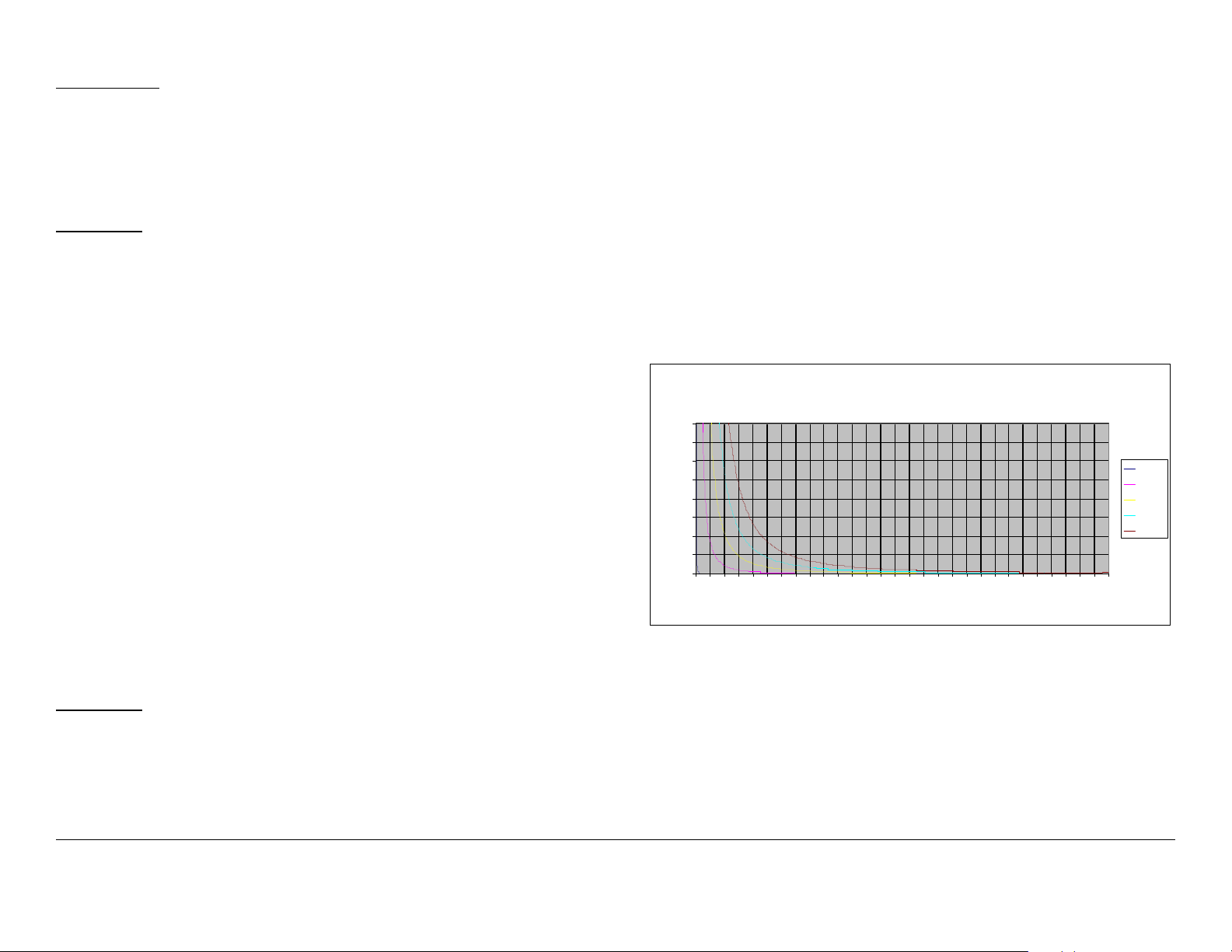
The examples shown in Figure 1 and Figure 2 are typical graphs
showing the permissible exposure distance for various antennas.
The plots provide the maximum permissible output of the
DXL5000 Transmitter System at 1 Watt and 2 Watts of RF power
for all frequency bands with digital modulation outputs.
MRC, in accordance with the requirements set forth by the FCC,
provides this information as a guide to the user. It is assumed
that the users of this equipment are licensed and qualified to
operate the equipment per the guidelines and recommendations
contained within the product user guides and in accordance with
any FCC rules that may apply.
Calculation steps:
1. [P] RF power input. Convert watts to milliwatts = Watts *
1000
2. [G] Antenna gain dBi. Convert to numeric gain = Antilog
(dBi/10)
3. [EIRP] Multiply P * G
4. [R] Convert centimeters to feet = Centimeters * .0328
5. Square R
6. Multiply R² * 4π
7. [S] Divide (R² * 4π) into EIRP
S = Power Density in milliwatts per square centimeters. Note:
At frequencies above 1500 MHz, S must not be greater than 1.
Reference
FCC OET Bulletin 65, August 1997 - Evaluating Compliance with
FCC Guidelines for Human Exposure to Radio Frequency
Electromagnetic Fields
Figure 1: Digital Modulation - Low Power
80
70
60
50
40
30
20
10
Power Density (mW/cm^2)
0
0 2 4 6 8 10121416182022242628303234363840424446485052545658
Maximum Permissible Exposure
A ll Ban ds, St an dard P owe r 1 Wat t (+30 dB m)
Distan ce in Feet
0dBi
29dBi
36dBi
40dBi
43dBi
Notices Notices-iiiDXL5000 User and Technical Manual
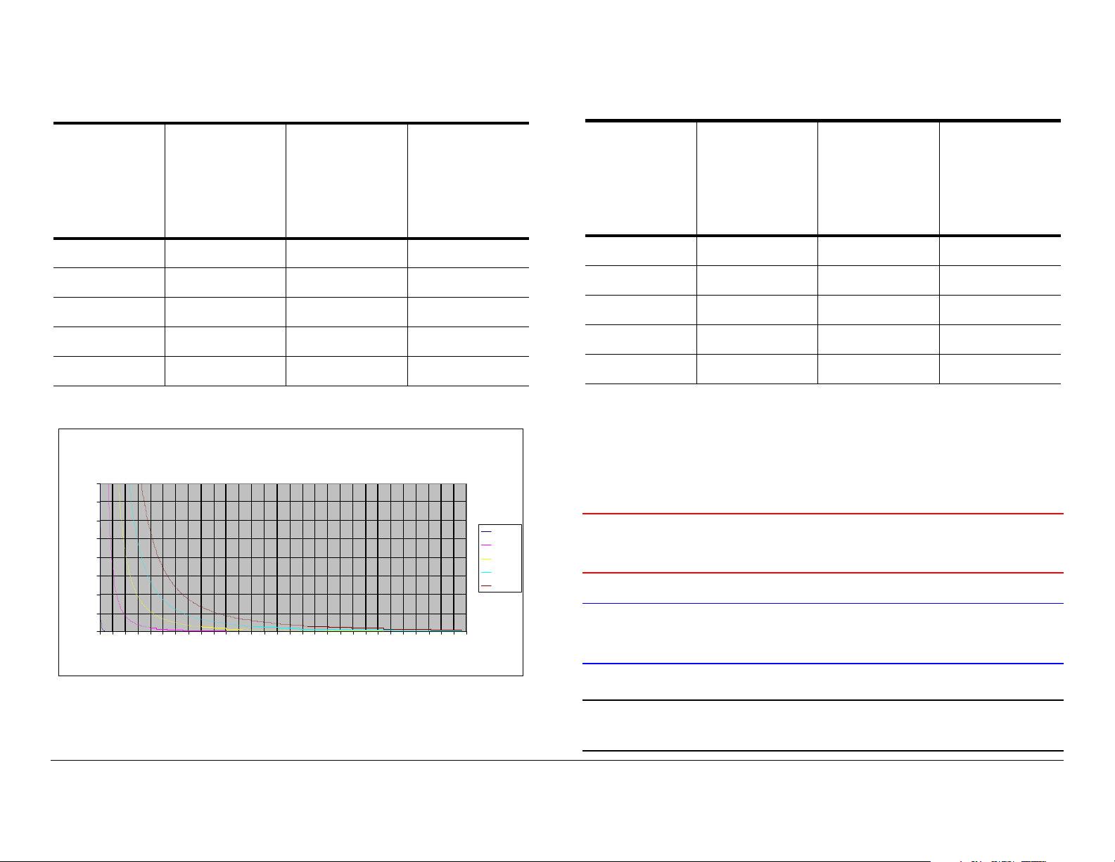
Table 1 reflects the graphic representations in Figure 1 above.
Table 1: Minimum Distance - Low Power
Minimum
Antenna
Gain (dBi)
Distance
from
Antenna
(cm)
0 9 3.54 0.30
29 252 99.19 8.27
36 563 221.60 18.47
40 893 351.48 29.29
43 1261 496.33 41.36
Minimum
Distance
from
Antenna
(inch)
Figure 2: Digital Modulation - High Power
80
70
60
50
40
30
20
10
Power Density (mW/cm^2)
0
0246810121416182022242628303234363840424446485052545658
Maximum Permissible Exposure
All Bands, High Power 2 Watts (+33dBm)
Dist ance in Feet
Minimum
Distance
from
Antenna
(Feet)
0dBi
29dBi
36dBi
40dBi
43dBi
Table 2: Minimum Distance - High Power
Minimum
Antenna
Gain (dBi)
Distance
from
Antenna
(cm)
0 13 5.12 0.43
29 356 140.12 11. 6 8
36 797 313.70 26.14
40 1262 496.72 41.39
43 1783 701.79 58.48
Minimum
Distance
from
Antenna
(inch)
Minimum
Distance
from
Antenna
(Feet)
Conventions
Pay special attention to information marked in one of the
following ways:
WARNING
CAUTION
Follow WARNINGS closely to prevent
personal injury or death.
Follow CAUTIONS to prevent damage to
the equipment.
Table 2 reflects the graphic representations in Figure 2 above.
Note
Notes provide additional information to assist you
in using and maintaining the equipment.
Notices Notices-ivDXL5000 User and Technical Manual
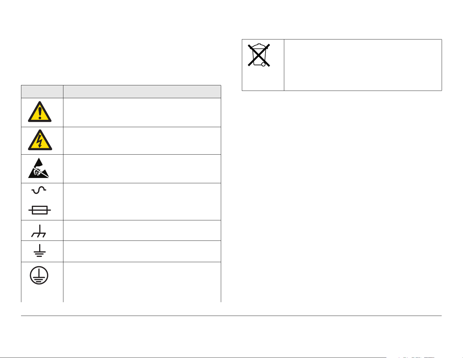
Symbols Used
The following symbols may be used on the equipment or may be
contained in this manual:
Symbol Meaning
WARNING: General Warning. Risk of Danger
WARNING: Risk of Electric Shock
CAUTION: Electrostatic Discharge. Possible
Damage to Equipment
Fuse - Identifies fuses or their location.
-OR-
Waste Electrical and Electronic Equipment
(WEEE) - The product must not be disposed of
with other waste at the end of its life cycle. It is
the user’s responsibility to dispose of the waste
equipment by handing it over to a designated
collection point for recycling.
Frame or Chassis Ground - Identifies the frame or
chassis terminal.
Earth Ground - Identifies the earth ground terminal
Protective Earth Ground - Identifies any terminal
which is intended for connection to an external
conductor for protection against electric shock in
case of a fault, or the terminal on a protective earth
electrode.
Notices Notices-vDXL5000 User and Technical Manual

Notices Notices-viDXL5000 User and Technical Manual

Contents
NOTE TO USER - - - - - - - - - - - - - - - - - - - - - - - - - -i
Overview - - - - - - - - - - - - - - - - - - - - - - - - - - - - - - - - - - - i
Initial Setup- - - - - - - - - - - - - - - - - - - - - - - - - - - - - - - - - - i
Avoid Potential Operational Problems - - - - - - - - - - - - - - - i
Routine Operations- - - - - - - - - - - - - - - - - - - - - - - - - - i
Notices - - - - - - - - - - - - - - - - - - - - - - - - - - - - - - - - i
About This Manual - - - - - - - - - - - - - - - - - - - - - - - - - - - - i
Copyright - - - - - - - - - - - - - - - - - - - - - - - - - - - - - - - - - - - i
Proprietary Material - - - - - - - - - - - - - - - - - - - - - - - - - - - - i
Quality Certification - - - - - - - - - - - - - - - - - - - - - - - - - - - - i
General Safety Information- - - - - - - - - - - - - - - - - - - - - - - i
DXL5000 System Receiver - - - - - - - - - - - - - - - - - - - - ii
DXL5000 System Transmitter - - - - - - - - - - - - - - - - - - ii
WARNING - RF Power Hazard - - - - - - - - - - - - - - - - - ii
RF Exposure - Safe Working Distances - - - - - - - - - - - ii
Conventions - - - - - - - - - - - - - - - - - - - - - - - - - - - - - - - - iv
Symbols Used- - - - - - - - - - - - - - - - - - - - - - - - - - - - - - - - v
Contents - - - - - - - - - - - - - - - - - - - - - - - - - - - - - - 1
Introduction - - - - - - - - - - - - - - - - - - - - - - - - - - - 1-1
For Whom It’s Written - - - - - - - - - - - - - - - - - - - - - - - - 1-1
Related Documents - - - - - - - - - - - - - - - - - - - - - - - - - - 1-1
Ordering Documentation - - - - - - - - - - - - - - - - - - - - - - 1-1
Calling for Service - - - - - - - - - - - - - - - - - - - - - - - - - - - 1-1
Tell Us What You Think! - - - - - - - - - - - - - - - - - - - - - - 1-1
System Description - - - - - - - - - - - - - - - - - - - - - - - - - - 1-2
Configuration Options - - - - - - - - - - - - - - - - - - - - - - 1-2
Configuration Descriptions - - - - - - - - - - - - - - - - - - 1-2
Power Options - - - - - - - - - - - - - - - - - - - - - - - - - - - 1-3
Band and Frequency Options - - - - - - - - - - - - - - - - 1-3
Mounting and Deployment Options - - - - - - - - - - - - 1-3
System Integration - - - - - - - - - - - - - - - - - - - - - - - - 1-3
DXL5000 Connections - - - - - - - - - - - - - - - - - - - - - - - - 1-3
Operation - - - - - - - - - - - - - - - - - - - - - - - - - - - - 2-1
Chapter Overview - - - - - - - - - - - - - - - - - - - - - - - - - - - 2-1
Overview of DXL5000 Transmitter and Receiver Controls,
Indicators, and Connectors - - - - - - - - - - - - - - - - - - - - - 2-1
DXL5000 Transmitter Controls, Indicators, and
Connectors - - - - - - - - - - - - - - - - - - - - - - - - - - - - - - 2-1
DXL5000 Receiver Controls, Indicators, and
Connectors - - - - - - - - - - - - - - - - - - - - - - - - - - - - - - 2-3
Preparing for Operation - - - - - - - - - - - - - - - - - - - - - - - 2-5
Fixed Installation - - - - - - - - - - - - - - - - - - - - - - - - - - 2-5
Powering the DXL5000 System Transmitter- - - - - - - 2-6
Powering the DXL5000 System Receiver - - - - - - - - 2-7
Initial DXL5000 System Setup - - - - - - - - - - - - - - - - - - - 2-9
Transmitter General Procedures - - - - - - - - - - - - - - - - 2-11
Review DXL5000 System Transmitter Status - - - - - 2-12
Perform DXL5000 System Transmitter Setup- - - - - 2-13
Review Transmitter Alarms - - - - - - - - - - - - - - - - - 2-16
Receiver General Procedures - - - - - - - - - - - - - - - - - - 2-18
Review DXL5000 System Receiver Status- - - - - - - 2-19
Perform DXL5000 System Receiver Setup - - - - - - 2-20
Review Receiver Alarms - - - - - - - - - - - - - - - - - - - 2-23
Advanced Operation Procedures - - - - - - - - - - - - - - - - 2-24
User Name and Password Setup - - - - - - - - - - - - - 2-24
Download New System Software - - - - - - - - - - - - - 2-25
Troubleshooting - - - - - - - - - - - - - - - - - - - - - - - 3-1
Chapter Overview - - - - - - - - - - - - - - - - - - - - - - - - - - - 3-1
Errors/Alarms- - - - - - - - - - - - - - - - - - - - - - - - - - - - - - - 3-1
Installation - - - - - - - - - - - - - - - - - - - - - - - - - - - 4-1
Chapter Overview - - - - - - - - - - - - - - - - - - - - - - - - - - - 4-1
Unpacking - - - - - - - - - - - - - - - - - - - - - - - - - - - - - - - - 4-1
Initial Inspection - - - - - - - - - - - - - - - - - - - - - - - - - - - - - 4-1
Damage in Shipment - - - - - - - - - - - - - - - - - - - - - - - - - 4-2
Contents 1DXL5000 User and Technical Manual

Installing the DXL5000 System - - - - - - - - - - - - - - - - - - 4-2
Site Preparation - - - - - - - - - - - - - - - - - - - - - - - - - - 4-2
Mounting the DXL5000 Transmitter and Receiver - - 4-2
Power Connections - - - - - - - - - - - - - - - - - - - - - - - - - - 4-4
Power Requirements - - - - - - - - - - - - - - - - - - - - - - 4-4
Power Supply and Distribution - - - - - - - - - - - - - - - - 4-4
Grounding - - - - - - - - - - - - - - - - - - - - - - - - - - - - - - - - 4-5
Connections - - - - - - - - - - - - - - - - - - - - - - - - - - - - - - - 4-5
Transmitter Rear Panel Connectors - - - - - - - - - - - - 4-5
Receiver Rear Panel Connectors - - - - - - - - - - - - - - 4-5
MGMT Connections - - - - - - - - - - - - - - - - - - - - - - 4-10
SUMMARY ALARM Connections- - - - - - - - - - - - - 4-10
CHAN1 and CHAN2 T1/E1 Connections- - - - - - - - 4-10
WAYSIDE DATA Connections - - - - - - - - - - - - - - - 4-11
CHAN1 and CHAN2 DATA Connections- - - - - - - - 4-11
Initial Power Up/Power Down - - - - - - - - - - - - - - - - - - 4-12
Checks Before Power-Up - - - - - - - - - - - - - - - - - - 4-12
Initial Power-Up - - - - - - - - - - - - - - - - - - - - - - - - - 4-12
Power Down - - - - - - - - - - - - - - - - - - - - - - - - - - - 4-12
Product Modifications - - - - - - - - - - - - - - - - - - - - - - - 4-13
Replacement Parts and Supported Repairs - - - 5-1
Chapter Overview - - - - - - - - - - - - - - - - - - - - - - - - - - - 5-1
Replacement Parts- - - - - - - - - - - - - - - - - - - - - - - - - - - 5-1
External Cables - - - - - - - - - - - - - - - - - - - - - - - - - - 5-1
AC Power Fuses - - - - - - - - - - - - - - - - - - - - - - - - - - 5-1
Supported Repairs - - - - - - - - - - - - - - - - - - - - - - - - - - - 5-1
Theory of Operation - - - - - - - - - - - - - - - - - - - - 6-1
Chapter Overview - - - - - - - - - - - - - - - - - - - - - - - - - - - 6-1
System Architecture - - - - - - - - - - - - - - - - - - - - - - - - - - 6-1
General - - - - - - - - - - - - - - - - - - - - - - - - - - - - - - - - 6-1
DXL5000 Transmitter - - - - - - - - - - - - - - - - - - - - - - 6-1
DXL5000 Receiver - - - - - - - - - - - - - - - - - - - - - - - - 6-1
DXL5000 Transmitter and Receiver Software - - - - - - - - 6-4
Index- - - - - - - - - - - - - - - - - - - - - - - - - - - - - - - - - - 1
Contents Contents-2DXL5000 User and Technical Manual

1
Introduction
1.1 For Whom It’s Written
This manual is intended for use by qualified operators, installers,
and service personnel. Users of this manual should already be
familiar with the basic concepts of radio, video, and audio.
1.4 Calling for Service
MRC Technical Support is available 24 hours a day, 7 days a
week. During regular business hours you can reach our expert
staff directly.
Business Hours: Monday - Friday
8:00 AM - 5:00PM Eastern Time (US)
(0800 - 1700 hrs US ET)
1.2 Related Documents
• Glossary of Terms and Abbreviations (Part No. 400576-1)
• Channels and Frequencies Technical Information (Part
No. 400580-1)
1.3 Ordering Documentation
The above manual may be ordered by contacting MRC
Customer Service:
Business Hours: Monday - Friday
8:00 AM - 5:00 PM Eastern Time (US)
(0800 - 1700 hrs US ET)
Telephone: 800.490.5700 (Press 3)
+1.978.671.5700 (Press 3)
E-mail: customerservice@mrcbroadcast.com
When contacting Customer Service, please have the following
information available.
• Model number and serial number of the unit. This is
located on a label on the bottom of each unit.
• Approximate purchase date.
Telephone: 888.777.9221 (US and Canada)
+1.978.671.5929
E-mail: technicalsupport@mrcbroadcast.com
After regular business hours and on weekends and holidays, you
can also reach our expert staff as follows:
Telephone: 888.777.9221 (US and Canada)
+1.978.671.5929
Your call will be automatically forwarded to the on-call Technical
Support specialist.
When contacting Technical Support, please have the following
information available:
• Model number and serial number of the unit. This is
located on a label on the bottom of each unit.
• Approximate purchase date.
1.5 Tell Us What You Think!
We’d appreciate any comments or suggestions you have about
this manual. The more feedback we get, the better the manuals
get!
Introduction 1-1DXL5000 User and Technical Manual
If you’re viewing this manual electronically, it’s easy - just click on
the link below to send us an E-mail.
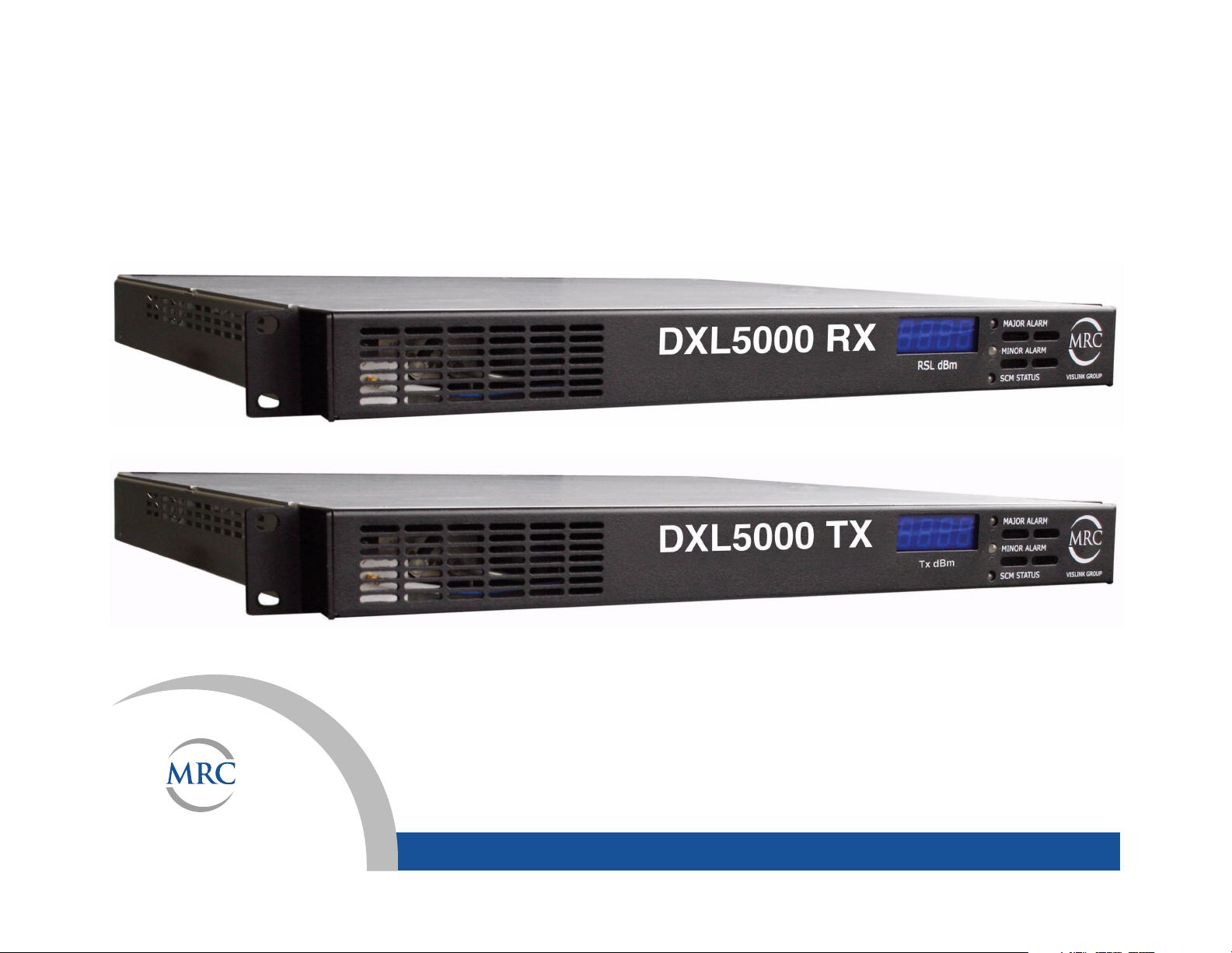
Figure 1-1: DXL5000 System - Typical
Feedback
Or, you can E-mail our Technical Support team at:
technicalsupport@mrcbroadcast.com
Be sure to tell us what product you’re writing about, and which
manual.
1.6 System Description
The DXL5000 Digital Microwave System is a cost effective,
highly reliable, flexible, and compact microwave link for long and
medium haul applications, including Studio-to-Transmitter Links
(STL) and Transmitter-to-Studio Links (TSL), multi-hop and
multi-channel broadcast, Community Antenna Television
(CATV), Standard Definition Television (SDTV), High Definition
Television (HDTV), and Analog Television (ATV) video system
networks.
The DXL5000 System is designed to provide high quality digital
format transmission under a Single Carrier Modulation (SCM)
scheme. The DXL5000 System can be configured as either a
simplex or a duplex system. Protection options, such as hot
standby, including space and frequency diversity, will be
available in the future. A high power option is also available for
severe fading transmission environments.
The DXL5000 System consists of a digital microwave
Transmitter and a digital microwave Receiver. See Figure 1-1.
DXL5000 Receiver
DXL5000 Transmitter
The DXL5000 System is designed to be controlled locally or
remotely using a Windows-based PC or laptop computer.
1.6.1 Configuration Options
The DXL5000 System is currently available in the following
configurations:
•Simplex
•Duplex
• Non-protected
• TX, RX, Duplex
• Space Diversity RX
Consult your Sales Representative or contact the factory for the
latest information.
1.6.2 Configuration Descriptions
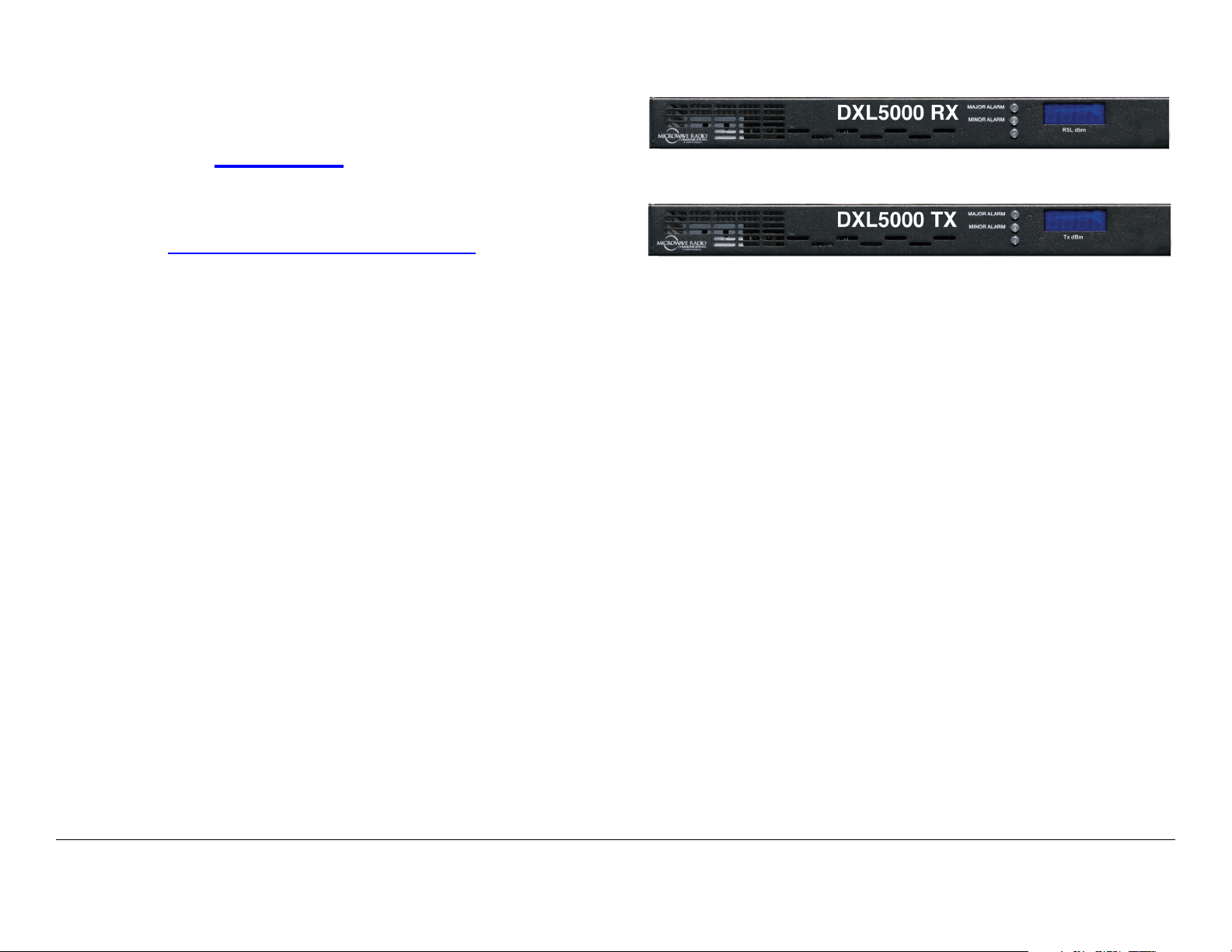
General The front panels of the DXL5000 Transmitter and
Receiver each contain three status LEDs and a 4-digit display.
DXL5000 Transmitter The rear panel of the DXL5000
Transmitter contains the I/O connectors, the AC input power
Introduction 1-2DXL5000 User and Technical Manual
connector, and a power fuse.
• 5.925 GHz – 6.425 GHz (10MHz Channel)
DXL5000 Receiver The rear panel of the DXL5000 Receiver
contains the I/O connectors, the AC input power connector, and
a power fuse.
1.6.3 Power Options
The DXL5000 System Transmitter and Receiver each operate
on the following AC power sources:
120/240 VAC, 50/60 Hz
Fuse ratings for the AC power sources are shown in Table 1-1.
Table 1-1: Transmitter Fuse Ratings
Operating Voltage Fuse Rating
120 VAC, 50/60 Hz 3.0A, 250V, Slow Blow
240 VAC, 50/60 Hz 3.0A, 250V, Slow Blow
Table 1-2: Receiver Fuse Ratings
Operating Voltage Fuse Rating
120 VAC, 50/60 Hz 1.0A, 250V, Slow Blow
240 VAC, 50/60 Hz 1.0A, 250V, Slow Blow
• 6.425 GHz – 6.525 GHz (25MHz Channel)
• 6.525 GHz – 6.875 GHz (10MHz Channel)
• 6.875 GHz – 7.125 GHz (25MHz Channel)
• 7.1 GHz – 8.4 GHz (20MHz Channel)
• 8.2 GHz – 8.5 GHz (19MHz Channel)
• 10.7 GHz – 11.7 GHz (40MHz Channel)
• 12.2 GHz – 12.7 GHz (24MHz Channel)
• 12.7 GHz – 13.25 GHz (25MHz Channel).
1.6.5 Mounting and Deployment Options
For fixed installation applications, the DXL5000 System
Transmitter and Receiver are usually mounted in a standard 19inch (48.3 cm) rack. Power is supplied by the site or facility
power source.
For more details on installation of the DXL5000 System, see the
“Installation” Chapter on page 4-1 for additional information.
1.6.6 System Integration
Refer to the “Installation” Chapter on page 4-1 for additional
information.
1.6.4 Band and Frequency Options
The DXL5000 System can be ordered to cover the following
frequency bands.
• 1.99 GHz – 2.5 GHz (12/17MHz Channel)
• 4.94 GHz – 4.99 GHz (10MHz Channel)
Once the DXL5000 System is installed, connected, and powered
up, system settings must be selected or modified using a PC or a
laptop computer. Changes to system settings can be performed
either locally or from a remote location via an Ethernet
connection.
1.7 DXL5000 Connections
For details on connections between DXL5000 Transmitter and
Receiver components, see the “Installation” Chapter on page 4-
1.
Introduction 1-3DXL5000 User and Technical Manual

Introduction 1-4DXL5000 User and Technical Manual
2
Operation
2.1 Chapter Overview
This chapter provides the information that will enable you to
operate your DXL5000 Digital Microwave System (DXL5000).
Advanced Operation Procedures 2-24
User Name and Password Setup 2-24
Download New System Software 2-25
2.2 Overview of DXL5000 Transmitter
and Receiver Controls, Indicators, and
Here are the topics covered:
Topic Page
Overview of DXL5000 Transmitter and Receiver Controls, Indicators, and Connectors
DXL5000 Transmitter Controls, Indicators, and
Connectors
DXL5000 Receiver Controls, Indicators, and
Connectors
Preparing for Operation 2-5
Fixed Installation 2-5
Powering the DXL5000 System Transmitter 2-6
Powering the DXL5000 System Receiver 2-7
Initial DXL5000 System Setup 2-9
Transmitter General Procedures 2-11
Review DXL5000 System Transmitter Status 2-12
Perform DXL5000 System Transmitter Setup 2-13
Review Transmitter Alarms 2-16
Receiver General Procedures 2-18
Review DXL5000 System Receiver Status 2-19
Perform DXL5000 System Receiver Setup 2-20
Review Receiver Alarms 2-23
2-1
2-1
2-3
Connectors
This section describes the controls, indicators, and connectors
used on the DXL5000 System Transmitter and Receiver.
2.2.1 DXL5000 Transmitter Controls, Indicators, and Connectors
Controls, indicators, and connectors contained on the DXL5000
System Transmitter are shown in Figure 2-1 on page 2-2 and are
described in the following paragraphs.
TX POWER Display The TX POWER 4-digit LED display
indicates the current transmitter output power level in dBm.
MAJOR ALARM LED When flashing amber, the MAJOR
ALARM LED indicates the PA is off and the summary alarm
relay has tripped; when amber, a major alarm has been detected
but no action has been taken.
MINOR ALARM LED When green, the MINOR ALARM LED
indicates no alerts are present; when amber, indicates an alert is
present; and when red, an alert is present and the alert relay has
tripped.
SCM STATUS LED When green, the SCM STATUS LED
indicates no alarms are present; when amber, a minor alarm is
present; and when red, as major SCM alarm is present.
Operation 2-1DXL5000 User and Technical Manual
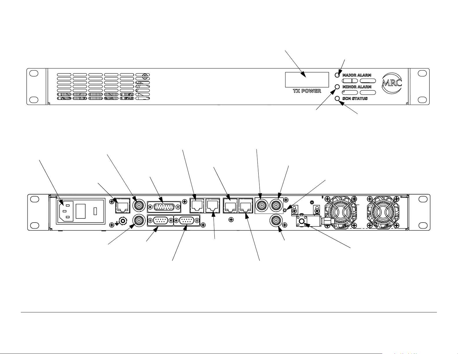
Figure 2-1: DXL5000 Transmitter Controls, Indicators, and Connectors
POWER IN
Connector
IF IN
Connector
MGMT
Connector
SUMMARY
ALARM
Connector
I
F
I
N
MGMT
I
F
M
O
N
DXL5000 TX
CHAN2 DATA
Connector
CHAN1 T1/E1
Connector
SUMMARY ALARM
CHAN2
DATA
IMC BUS WAYSIDE DATA
CHAN1
DATA
TX POWER
Display
ASI/DS3/E3 1
Connector
CHAN2
T1/E1
1
CHAN1
T1/E1
MINOR ALARM
LED
ASI/DS3/E3 2
Connector
ASI/DS3/E3
ASI/SMPTE310
2
RESET
RF OUT
MAJOR ALARM
LED
SCM STATUS
LED
RESET
Switch
IF MON
Connector
IMC BUS
Connector
WAYSIDE DATA
Connector
CHAN1 DATA
Connector
Operation 2-2DXL5000 User and Technical Manual
ASI/SMPTE310
Connector
CHAN2 T1/E1
Connector
RF OUT
Connector

POWER IN Connector The POWER IN power connector
provides connection to the removable external power cable. The
power connector assembly also contains the AC power fuse.
ASI/SMPTE310 Connector The 75 ohm BNC female ASI/
SMPTE310 connector provides ASI or SMPTE310 inputs to the
unit.
MGMT Connector The RJ-45 MGMT connector provides 10
Base T Ethernet connection for remote control.
IF IN Connector The 75 ohm BNC female IF IN connector
provides the 70 MHz IF input to the unit.
SUMMARY ALARM Connector The DB-15 female SUMMARY
ALARM connector provides summary alarm data for common
faults and events.
CHAN1 and CHAN2 DATA Connectors The CHAN1 and
CHAN2 DATA RJ-45 connectors provide 10/100 Base T
Ethernet connections to the unit.
CHAN1 and CHAN2 T1/E1 Connectors The CHAN1 and
CHAN2 T1/E1 RJ-45 connectors provide T1/E1 input
connections for channels 1 and 2.
ASI/DS3/E3 1 and 2 Connectors The ASI/DS3/E3 1 and 2
BNC 75 ohm female connectors provide ASI or DS3/E3 inputs to
the unit.
RESET Switch When the RESET switch is pressed and held for
approximately 5 seconds, the IP address is reset to the factory
default IP address of 192.168.0.10, the subnet mask is reset to
the factory default subnet mask of 255.255.255.0, and the
default gateway is reset to the factory default subnet mask of
192.168.0.1. No other password or configuration settings are
effected.
WAYSIDE DATA Connector The WAYSIDE DATA DB-9 male
connector provides RS-232 connections for SCM operations.
IMC BUS Connector (Reserved for future use.)
IF MON Connector The 75 ohm BNC female IF MON
connector provides a 70 MHz output for external signal
monitoring purposes.
2.2.2 DXL5000 Receiver Controls, Indicators, and Connectors
Controls, indicators, and connectors contained on the DXL5000
System Receiver are shown in Figure 2-2 on page 2-4 and are
described in the following paragraphs.
RF OUT Connector The SMA 50 ohm female RF OUT
connector provides connection from the internal RF circulator to
the external antenna.
Operation 2-3DXL5000 User and Technical Manual
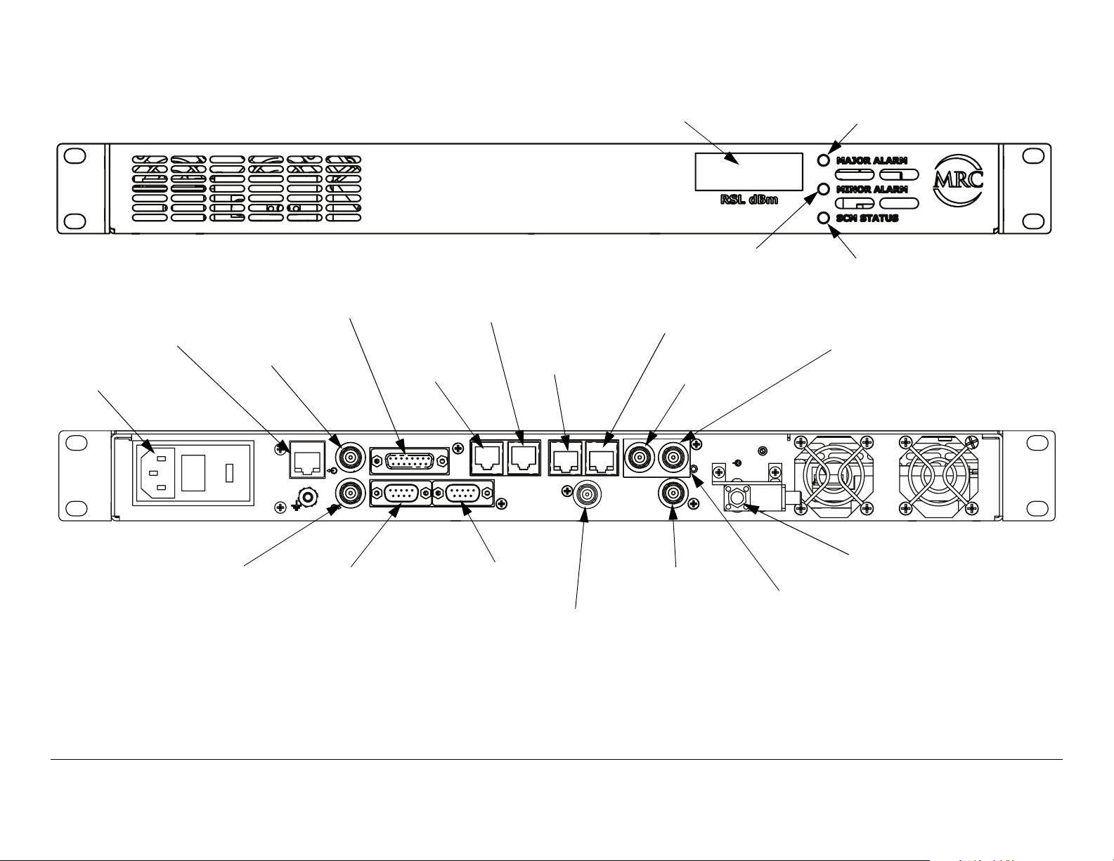
Figure 2-2: DXL5000 Receiver Controls, Indicators, and Connectors
MGMT
Connector
POWER IN
Connector
POWER IN
IF OUT
Connector
SUMMARY
ALARM
Connector
I
F
O
U
T
D
MGMT
I
V
I
N
DXL5000 RX
CHAN1
DATA
Connector
CHAN2
DATA
Connector
SUMMARY ALARM
WAYSIDE DATA
CHAN2
DATA
IMC BUS
RSL dBm
Display
CHAN1 T1/E1
Connector
CHAN1
DATA
CHAN1
T1/E1
DIV OUT
CHAN2
T1/E1
MINOR ALARM
LED
CHAN2 T1/E1
Connector
ASI/DS3/E3 1
Connector
ASI/DS3/E3
ASI/SMPTE310
2
RESET
1
MAJOR ALARM
LED
SCM STATUS
LED
ASI/DS3/E3 2
Connector
RF IN
DIV IN
Connector
WAYSIDE DATA
Connector
IMC BUS
Connector
Operation 2-4DXL5000 User and Technical Manual
DIV OUT
Connector
ASI/SMPTE310
Connector
RF IN
Connector
RESET
Switch

RSL dBm Display The RSL dBm 4-digit LED display indicates
the current receiver signal power level in dBm.
BNC 75 ohm female connectors provide ASI or DS3/E3 outputs
from the unit.
MAJOR ALARM LED When flashing amber, the MAJOR
ALARM LED indicates the PA is off and the summary alarm
relay has tripped; when amber, a major alarm has been detected
but no action has been taken.
MINOR ALARM LED When green, the MINOR ALARM LED
indicates no alerts are present; when amber, indicates an alert is
present; and when red, an alert is present and the alert relay has
tripped.
SCM STATUS LED When green, the SCM STATUS LED
indicates no alarms are present; when amber, a minor alarm is
present; and when red, as major SCM alarm is present.
POWER IN Connector The POWER IN power connector
provides connection to the removable external power cable. The
power connector assembly also contains the AC power fuse.
MGMT Connector The RJ-45 MGMT connector provides 10
Base T Ethernet connection for remote control.
IF OUT Connector The 75 ohm BNC female IF OUT connector
provides the 70 MHz IF output from the unit.
SUMMARY ALARM Connector The DB-15 SUMMARY
ALARM female connector provides summary alarm data for
common faults and events.
RF IN Connector The SMA 50 ohm female RF IN connector
provides the 70 MHz input from the external antenna.
RESET Switch When the RESET switch is pressed and held for
approximately 5 seconds, the IP address is reset to the factory
default IP address of 192.168.0.10, the subnet mask is reset to
the factory default subnet mask of 255.255.255.0, and the
default gateway is reset to the factory default subnet mask of
192.168.0.1. No other password or configuration settings are
effected.
ASI/SMPTE310 Connector The 75 ohm BNC female ASI/
SMPTE310 connector provides ASI or SMPTE310 outputs from
the unit.
DIV OUT Connector The 75 ohm BNC female DIV OUT
connector provides the diversity receive output from the unit.
IMC BUS Connector The IMC BUS DB-9 male connector
provides RS-232 or RS-485 inputs to the unit.
WAYSIDE DATA Connector The WAYSIDE DATA DB-9 male
connector provides connections for MPEG decoder Wayside
data.
DIV IN Connector The 75 ohm BNC female DIV IN connector
provides the diversity receive input to the unit.
CHAN1 and CHAN2 DATA Connectors The CHAN1 and
CHAN2 DATA RJ-45 connectors provides 10/100 Base T
Ethernet connections to the unit.
CHAN1 and CHAN2 T1/E1 Connectors The CHAN1 and
CHAN2 T1/E1 RJ-45 connectors provide T1/E1 output
connections for channels 1 and 2.
ASI/DS3/E3 1 and 2 Connectors The ASI/DS3/E3 1 and 2
2.3 Preparing for Operation
Each installation or deployment will have its own specific tasks
according to the application and the installed hardware.
2.3.1 Fixed Installation
For fixed installations, the DXL5000 System is typically mounted
Operation 2-5DXL5000 User and Technical Manual

in a standard 19-inch (48.3 cm) rack. The cabling is permanently
installed and power comes from the facility or site power source.
Each installation will have its own specific tasks according to the
application and the installed hardware options.
For installation information, refer to the “Installation” section on
page 4-1.
2.3.2 Powering the DXL5000 System Transmitter
CAUTION
Corruption of software contained in the
DXL5000 System Transmitter may occur if
proper power down or power up of the
DXL5000 does not occur.
The software will become corrupted and the
DXL5000 System Transmitter may have to
be returned to the factory for repair.
CAUTION
Note
If power is accidentally lost, do not
immediately re-apply power to the DXL5000
System Transmitter.
Internal software corruption may occur if
power is applied immediately after a power
loss.
To avoid possible software corruption, wait a
minimum of 10 seconds before re-applying
power.
If you are unsure of the power requirements or
connections to the DXL5000 System Transmitter,
refer to the “Installation” section on page 4-1 .
The DXL5000 System Transmitter must be properly powered up
and powered down to prevent possible corruption of the software
contained in the radio. It will take approximately 30 seconds for
the DXL5000 System Transmitter to initialize.
Power to the DXL5000 System Transmitter must never be cycled
off and on without a minimum delay of 10 seconds between
removal of power and application of power.
Conversely, power to the DXL5000 System Transmitter must
never be cycled to on and then immediately to off, as corruption
of software contained in the radio may also occur.
Power Up
The steps required to properly power up the DXL5000 System
Transmitter are contained in the following steps.
Operation 2-6DXL5000 User and Technical Manual
Note
1. Verify the power cable is properly connected to the
When the DXL5000 System Transmitter is
powered up, it will automatically return to the last
settings that were in use when the unit was
powered down.
The unit will also resume transmitting if the unit
was transmitting when it was powered down, as
long as there are no alarms preventing
transmitting.
DXL5000 System Transmitter rear panel AC POWER
IN connector.
 Loading...