

Page 1
DXL5000
Digital Microwave System
User and Technical Manual
Manual Part No. 400571-1 Rev. A July 2009
Page 2

Page 3

NOTE TO USER
Overview
The DXL5000 Digital Microwave System (DXL5000) is a stateof-the-art radio system. The DXL5000 Transmitter and Receiver
contain central processors used to control all functions and
operations of the system. To avoid potential software hang-ups
or software corruption, please read and follow the guidelines
contained in the following paragraphs.
Initial Setup
The DXL5000 Transmitter and Receiver each contain central
processors that can only be controlled from a PC or laptop,
either locally or from a remote location.
Prior to using either the DXL5000 Transmitter and/or
Receiver, the IP, Subnet Mask, and Default Gateway
addresses must be selected by your System Administrator.
The IP, Subnet Mask, and Default Gateway addresses must
be assigned upon initial receipt of your DXL5000 System or
you will be unable to control your DXL5000 System.
Unless otherwise requested, the DXR unit will be shipped with a
default IP address of 192.168.0.10, a subnet mask of
255.255.255.0, and a default gateway of 192.168.0.1.
To enter the IP, Subnet Mask, and Default Gateway addresses,
the System Administrator must perform the “Initial DXL5000
System Setup” on page 2-9.
Once the IP, Subnet Mask, and Default Gateway addresses are
assigned, the System Administrator will be able to assign up to
four user names and passwords.
To assign user names and passwords, perform the “Receiver
General Procedures” on page 2-18.
Avoid Potential Operational Problems
Information contained in the following paragraphs identify
potential problems that can be avoided by reading and following
the operating procedures provided in this manual.
To avoid potential operational problems, please review the
information contained in the “Operation” Chapter on page 2-1.
The Operation Chapter contains procedures that, when
performed correctly, will eliminate potential problems that could
be caused by operator error or by lack of experience with the
DXL5000 system.
Routine Operations
It is highly recommended that remote operations be performed
using a Microsoft Windows-based PC that meets the following
requirements:
• Microsoft Windows XP Operating System with SP2
• 1.2 GHz processor
• 500 MB of system memory
• 1.0 Gb of free hard disk space
NOTE TO USER iDXL5000 User and Technical Manual
Page 4

• Super VGA 800 x 600 pixels
• Internet Explorer 7.0 or later
Remote operations are best performed using Internet
Explorer 7.0 or later.
Notes
NOTE TO USER iiDXL5000 User and Technical Manual
Page 5

Notices
About This Manual
Microsoft®, Windows®, and Internet Explorer® are registered
trademarks of Microsoft Corporation in the United States and/or
other countries.
Part number 400571-1
Revision A July 2009
DXL5000 Digital Microwave System (DXL5000)
Copyright
The information contained in this manual remains the property of
Microwave Radio Communications (MRC) and may not be used,
disclosed, or reproduced in any form whatsoever, without the
prior written consent of MRC.
MRC reserves the right to make changes to equipment and
specifications of the product described in this manual at any time
without notice and without obligation to notify any person of such
changes.
© 2009 Microwave Radio Communications
Microwave Radio Communications
101 Billerica Avenue - Bldg. 6
North Billerica, MA 01862-1256 USA
Proprietary Material
The information and design contained within this manual was
originated by and is the property of MRC. MRC reserves all
patent proprietary design, manufacturing, reproduction use, and
sales rights thereto, and to any articles disclosed therein, except
to the extent rights are expressly granted to others. The
foregoing does not apply to vendor proprietary parts.
MRC has made every effort to ensure the accuracy of the
material contained in this manual at the time of printing. As
specifications, equipment, and this manual are subject to change
without notice, MRC assumes no responsibility or liability
whatsoever for any errors or inaccuracies that may appear in this
manual or for any decisions based on its use. This manual is
supplied for information purposes only and should not be
construed as a commitment by MRC.
Quality Certification
Microwave Radio Communications is certified to ISO 9001:2000.
TEL: 800.490.5700
+1.978.671.5700
Printed in U.S.A.
The Microwave Radio Communications and Vislink trademarks
and other trademarks are registered trademarks in the United
States and/or other countries.
General Safety Information
The following safety requirements, as well as local site
requirements and regulations, must be observed by personnel
operating and maintaining the equipment covered by this manual
to ensure awareness of potential hazards.
Notices Notices-iDXL5000 User and Technical Manual
Page 6

DXL5000 System Receiver
Communications Commission (FCC).
This equipment has been tested and found to comply with the
limits for a Class A digital Device, pursuant to Part 15 of the FCC
Rules. These limits are designed to provide reasonable
protection against harmful interference when the equipment is
operated in a commercial environment. This equipment
generates, uses, and can radiate radio frequency energy and, if
not installed and used in accordance with the instruction manual,
may cause harmful interference to radio communications.
Operation of this equipment in a residential area is likely to
cause harmful interference in which case the user will be
required to correct the interference at his own expense.
DXL5000 System Transmitter
Changes or modifications not expressly approved by MRC could
void the user’s authority to operate the equipment.
WARNING - RF Power Hazard
High levels of RF power are present in the unit. Exposure to RF
or microwave power can cause burns and may be harmful to
health.
Remove power from the unit before disconnecting any RF cables
and before inspecting damaged cables and/or antennas.
The DXL5000 Transmitter is designed to provide services to
broadcast ENG users under CFR 74 subpart F and 74.601 TV
pickup stations. This unit, operated without an antenna, will not
create RF energy exceeding 1.0 mW/cm2, the FCC limit for
exposure. Once connected to an antenna, the potential for
harmful exposure will be greatly enhanced.
In this situation, a certain distance from the radiator is to be
maintained. Calculations need to be performed to understand
what that safe margin for exposure is. This is known as the
Maximum Permissible Exposure (MPE) limit.
Note
Calculations provided are for common antennas often utilized in
the ENG environment. The following formula used is that
suggested by OET 65.
Hazardous RF radiation limits and recommended
distances may vary by country. Ensure that all
applicable state and federal regulations are
observed when using this transmitter.
Calculating MPE
EIRP = P * (10 ^ (G / 10)) = (antilog of G/10) * P
Avoid standing in front of high gain antennas (such as a dish
antenna) and never look into the open end of a waveguide or
cable where RF power may be present.
RF Exposure - Safe Working Distances
MRC provides this warning for safety purposes with the intent to
inform the user of the potential hazard to RF exposure. The
following guidelines for safe operation were derived from OET
bulletin 65, August 1997, as recommended by the Federal
P = RF power delivered to the antenna in mW
G = Power gain of the antenna in the direction of interest relative
to an isotropic radiator
R = distance to the center of radiation of the antenna in
centimeters
S = MPE in mW/cm² (milliwatts per square centimeters)
Notices Notices-iiDXL5000 User and Technical Manual
Page 7
Conversions
dBi to numeric gain = Antilog (dBi/10)
Feet to centimeters = Feet * 30.48
Centimeters to Feet = cm * .0328
4 π = 12.57
User Input
RF power delivered to the antenna = Watts
Antenna gain (referenced to isotropic antenna) = dBi
Distance from the center of radiation = Feet
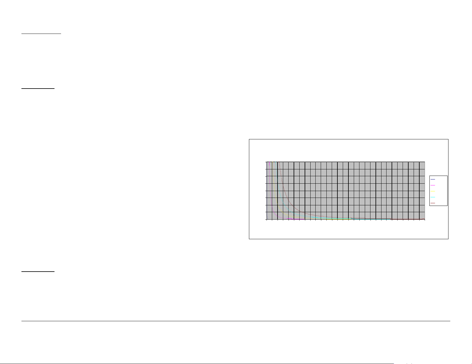
The examples shown in Figure 1 and Figure 2 are typical graphs
showing the permissible exposure distance for various antennas.
The plots provide the maximum permissible output of the
DXL5000 Transmitter System at 1 Watt and 2 Watts of RF power
for all frequency bands with digital modulation outputs.
MRC, in accordance with the requirements set forth by the FCC,
provides this information as a guide to the user. It is assumed
that the users of this equipment are licensed and qualified to
operate the equipment per the guidelines and recommendations
contained within the product user guides and in accordance with
any FCC rules that may apply.
Calculation steps:
1. [P] RF power input. Convert watts to milliwatts = Watts *
1000
2. [G] Antenna gain dBi. Convert to numeric gain = Antilog
(dBi/10)
3. [EIRP] Multiply P * G
4. [R] Convert centimeters to feet = Centimeters * .0328
5. Square R
6. Multiply R² * 4π
7. [S] Divide (R² * 4π) into EIRP
S = Power Density in milliwatts per square centimeters. Note:
At frequencies above 1500 MHz, S must not be greater than 1.
Reference
FCC OET Bulletin 65, August 1997 - Evaluating Compliance with
FCC Guidelines for Human Exposure to Radio Frequency
Electromagnetic Fields
Figure 1: Digital Modulation - Low Power
80
70
60
50
40
30
20
10
Power Density (mW/cm^2)
0
0 2 4 6 8 10121416182022242628303234363840424446485052545658
Maximum Permissible Exposure
A ll Ban ds, St an dard P owe r 1 Wat t (+30 dB m)
Distan ce in Feet
0dBi
29dBi
36dBi
40dBi
43dBi
Notices Notices-iiiDXL5000 User and Technical Manual
Page 8
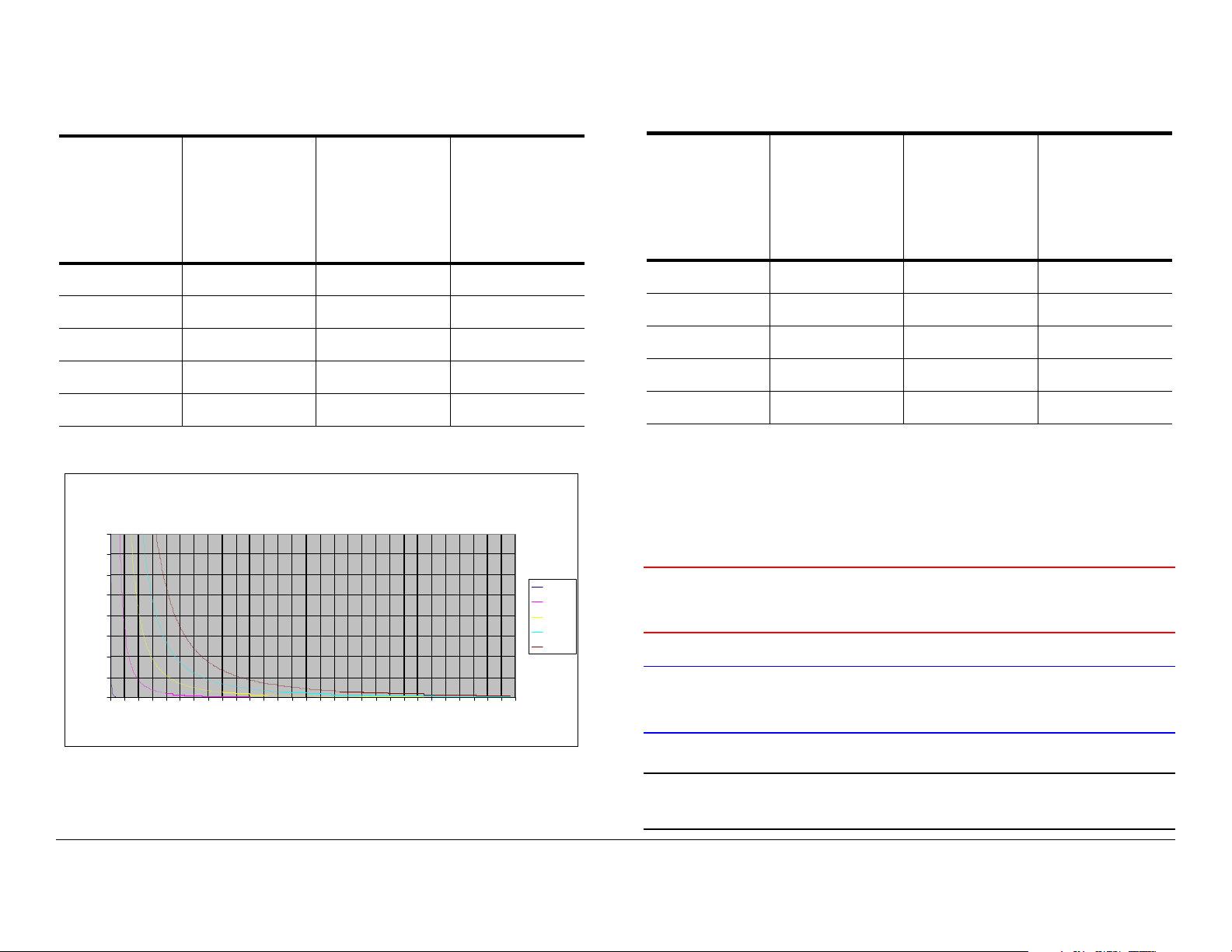
Table 1 reflects the graphic representations in Figure 1 above.
Table 1: Minimum Distance - Low Power
Minimum
Antenna
Gain (dBi)
Distance
from
Antenna
(cm)
0 9 3.54 0.30
29 252 99.19 8.27
36 563 221.60 18.47
40 893 351.48 29.29
43 1261 496.33 41.36
Minimum
Distance
from
Antenna
(inch)
Figure 2: Digital Modulation - High Power
80
70
60
50
40
30
20
10
Power Density (mW/cm^2)
0
0246810121416182022242628303234363840424446485052545658
Maximum Permissible Exposure
All Bands, High Power 2 Watts (+33dBm)
Dist ance in Feet
Minimum
Distance
from
Antenna
(Feet)
0dBi
29dBi
36dBi
40dBi
43dBi
Table 2: Minimum Distance - High Power
Minimum
Antenna
Gain (dBi)
Distance
from
Antenna
(cm)
0 13 5.12 0.43
29 356 140.12 11. 6 8
36 797 313.70 26.14
40 1262 496.72 41.39
43 1783 701.79 58.48
Minimum
Distance
from
Antenna
(inch)
Minimum
Distance
from
Antenna
(Feet)
Conventions
Pay special attention to information marked in one of the
following ways:
WARNING
CAUTION
Follow WARNINGS closely to prevent
personal injury or death.
Follow CAUTIONS to prevent damage to
the equipment.
Table 2 reflects the graphic representations in Figure 2 above.
Note
Notes provide additional information to assist you
in using and maintaining the equipment.
Notices Notices-ivDXL5000 User and Technical Manual
Page 9
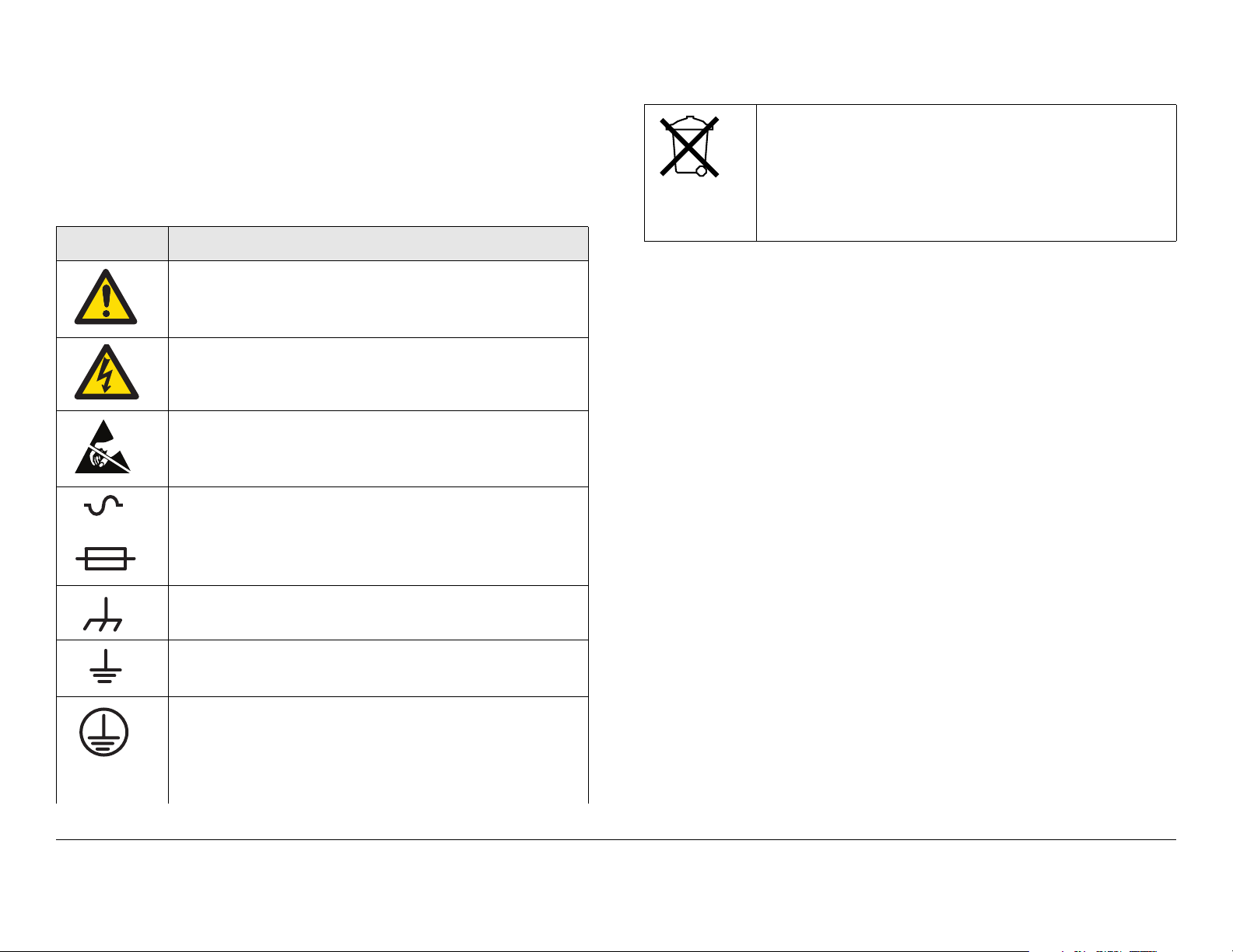
Symbols Used
The following symbols may be used on the equipment or may be
contained in this manual:
Symbol Meaning
WARNING: General Warning. Risk of Danger
WARNING: Risk of Electric Shock
CAUTION: Electrostatic Discharge. Possible
Damage to Equipment
Fuse - Identifies fuses or their location.
-OR-
Waste Electrical and Electronic Equipment
(WEEE) - The product must not be disposed of
with other waste at the end of its life cycle. It is
the user’s responsibility to dispose of the waste
equipment by handing it over to a designated
collection point for recycling.
Frame or Chassis Ground - Identifies the frame or
chassis terminal.
Earth Ground - Identifies the earth ground terminal
Protective Earth Ground - Identifies any terminal
which is intended for connection to an external
conductor for protection against electric shock in
case of a fault, or the terminal on a protective earth
electrode.
Notices Notices-vDXL5000 User and Technical Manual
Page 10

Notices Notices-viDXL5000 User and Technical Manual
Page 11

Contents
NOTE TO USER - - - - - - - - - - - - - - - - - - - - - - - - - -i
Overview - - - - - - - - - - - - - - - - - - - - - - - - - - - - - - - - - - - i
Initial Setup- - - - - - - - - - - - - - - - - - - - - - - - - - - - - - - - - - i
Avoid Potential Operational Problems - - - - - - - - - - - - - - - i
Routine Operations- - - - - - - - - - - - - - - - - - - - - - - - - - i
Notices - - - - - - - - - - - - - - - - - - - - - - - - - - - - - - - - i
About This Manual - - - - - - - - - - - - - - - - - - - - - - - - - - - - i
Copyright - - - - - - - - - - - - - - - - - - - - - - - - - - - - - - - - - - - i
Proprietary Material - - - - - - - - - - - - - - - - - - - - - - - - - - - - i
Quality Certification - - - - - - - - - - - - - - - - - - - - - - - - - - - - i
General Safety Information- - - - - - - - - - - - - - - - - - - - - - - i
DXL5000 System Receiver - - - - - - - - - - - - - - - - - - - - ii
DXL5000 System Transmitter - - - - - - - - - - - - - - - - - - ii
WARNING - RF Power Hazard - - - - - - - - - - - - - - - - - ii
RF Exposure - Safe Working Distances - - - - - - - - - - - ii
Conventions - - - - - - - - - - - - - - - - - - - - - - - - - - - - - - - - iv
Symbols Used- - - - - - - - - - - - - - - - - - - - - - - - - - - - - - - - v
Contents - - - - - - - - - - - - - - - - - - - - - - - - - - - - - - 1
Introduction - - - - - - - - - - - - - - - - - - - - - - - - - - - 1-1
For Whom It’s Written - - - - - - - - - - - - - - - - - - - - - - - - 1-1
Related Documents - - - - - - - - - - - - - - - - - - - - - - - - - - 1-1
Ordering Documentation - - - - - - - - - - - - - - - - - - - - - - 1-1
Calling for Service - - - - - - - - - - - - - - - - - - - - - - - - - - - 1-1
Tell Us What You Think! - - - - - - - - - - - - - - - - - - - - - - 1-1
System Description - - - - - - - - - - - - - - - - - - - - - - - - - - 1-2
Configuration Options - - - - - - - - - - - - - - - - - - - - - - 1-2
Configuration Descriptions - - - - - - - - - - - - - - - - - - 1-2
Power Options - - - - - - - - - - - - - - - - - - - - - - - - - - - 1-3
Band and Frequency Options - - - - - - - - - - - - - - - - 1-3
Mounting and Deployment Options - - - - - - - - - - - - 1-3
System Integration - - - - - - - - - - - - - - - - - - - - - - - - 1-3
DXL5000 Connections - - - - - - - - - - - - - - - - - - - - - - - - 1-3
Operation - - - - - - - - - - - - - - - - - - - - - - - - - - - - 2-1
Chapter Overview - - - - - - - - - - - - - - - - - - - - - - - - - - - 2-1
Overview of DXL5000 Transmitter and Receiver Controls,
Indicators, and Connectors - - - - - - - - - - - - - - - - - - - - - 2-1
DXL5000 Transmitter Controls, Indicators, and
Connectors - - - - - - - - - - - - - - - - - - - - - - - - - - - - - - 2-1
DXL5000 Receiver Controls, Indicators, and
Connectors - - - - - - - - - - - - - - - - - - - - - - - - - - - - - - 2-3
Preparing for Operation - - - - - - - - - - - - - - - - - - - - - - - 2-5
Fixed Installation - - - - - - - - - - - - - - - - - - - - - - - - - - 2-5
Powering the DXL5000 System Transmitter- - - - - - - 2-6
Powering the DXL5000 System Receiver - - - - - - - - 2-7
Initial DXL5000 System Setup - - - - - - - - - - - - - - - - - - - 2-9
Transmitter General Procedures - - - - - - - - - - - - - - - - 2-11
Review DXL5000 System Transmitter Status - - - - - 2-12
Perform DXL5000 System Transmitter Setup- - - - - 2-13
Review Transmitter Alarms - - - - - - - - - - - - - - - - - 2-16
Receiver General Procedures - - - - - - - - - - - - - - - - - - 2-18
Review DXL5000 System Receiver Status- - - - - - - 2-19
Perform DXL5000 System Receiver Setup - - - - - - 2-20
Review Receiver Alarms - - - - - - - - - - - - - - - - - - - 2-23
Advanced Operation Procedures - - - - - - - - - - - - - - - - 2-24
User Name and Password Setup - - - - - - - - - - - - - 2-24
Download New System Software - - - - - - - - - - - - - 2-25
Troubleshooting - - - - - - - - - - - - - - - - - - - - - - - 3-1
Chapter Overview - - - - - - - - - - - - - - - - - - - - - - - - - - - 3-1
Errors/Alarms- - - - - - - - - - - - - - - - - - - - - - - - - - - - - - - 3-1
Installation - - - - - - - - - - - - - - - - - - - - - - - - - - - 4-1
Chapter Overview - - - - - - - - - - - - - - - - - - - - - - - - - - - 4-1
Unpacking - - - - - - - - - - - - - - - - - - - - - - - - - - - - - - - - 4-1
Initial Inspection - - - - - - - - - - - - - - - - - - - - - - - - - - - - - 4-1
Damage in Shipment - - - - - - - - - - - - - - - - - - - - - - - - - 4-2
Contents 1DXL5000 User and Technical Manual
Page 12

Installing the DXL5000 System - - - - - - - - - - - - - - - - - - 4-2
Site Preparation - - - - - - - - - - - - - - - - - - - - - - - - - - 4-2
Mounting the DXL5000 Transmitter and Receiver - - 4-2
Power Connections - - - - - - - - - - - - - - - - - - - - - - - - - - 4-4
Power Requirements - - - - - - - - - - - - - - - - - - - - - - 4-4
Power Supply and Distribution - - - - - - - - - - - - - - - - 4-4
Grounding - - - - - - - - - - - - - - - - - - - - - - - - - - - - - - - - 4-5
Connections - - - - - - - - - - - - - - - - - - - - - - - - - - - - - - - 4-5
Transmitter Rear Panel Connectors - - - - - - - - - - - - 4-5
Receiver Rear Panel Connectors - - - - - - - - - - - - - - 4-5
MGMT Connections - - - - - - - - - - - - - - - - - - - - - - 4-10
SUMMARY ALARM Connections- - - - - - - - - - - - - 4-10
CHAN1 and CHAN2 T1/E1 Connections- - - - - - - - 4-10
WAYSIDE DATA Connections - - - - - - - - - - - - - - - 4-11
CHAN1 and CHAN2 DATA Connections- - - - - - - - 4-11
Initial Power Up/Power Down - - - - - - - - - - - - - - - - - - 4-12
Checks Before Power-Up - - - - - - - - - - - - - - - - - - 4-12
Initial Power-Up - - - - - - - - - - - - - - - - - - - - - - - - - 4-12
Power Down - - - - - - - - - - - - - - - - - - - - - - - - - - - 4-12
Product Modifications - - - - - - - - - - - - - - - - - - - - - - - 4-13
Replacement Parts and Supported Repairs - - - 5-1
Chapter Overview - - - - - - - - - - - - - - - - - - - - - - - - - - - 5-1
Replacement Parts- - - - - - - - - - - - - - - - - - - - - - - - - - - 5-1
External Cables - - - - - - - - - - - - - - - - - - - - - - - - - - 5-1
AC Power Fuses - - - - - - - - - - - - - - - - - - - - - - - - - - 5-1
Supported Repairs - - - - - - - - - - - - - - - - - - - - - - - - - - - 5-1
Theory of Operation - - - - - - - - - - - - - - - - - - - - 6-1
Chapter Overview - - - - - - - - - - - - - - - - - - - - - - - - - - - 6-1
System Architecture - - - - - - - - - - - - - - - - - - - - - - - - - - 6-1
General - - - - - - - - - - - - - - - - - - - - - - - - - - - - - - - - 6-1
DXL5000 Transmitter - - - - - - - - - - - - - - - - - - - - - - 6-1
DXL5000 Receiver - - - - - - - - - - - - - - - - - - - - - - - - 6-1
DXL5000 Transmitter and Receiver Software - - - - - - - - 6-4
Index- - - - - - - - - - - - - - - - - - - - - - - - - - - - - - - - - - 1
Contents Contents-2DXL5000 User and Technical Manual
Page 13

1
Introduction
1.1 For Whom It’s Written
This manual is intended for use by qualified operators, installers,
and service personnel. Users of this manual should already be
familiar with the basic concepts of radio, video, and audio.
1.4 Calling for Service
MRC Technical Support is available 24 hours a day, 7 days a
week. During regular business hours you can reach our expert
staff directly.
Business Hours: Monday - Friday
8:00 AM - 5:00PM Eastern Time (US)
(0800 - 1700 hrs US ET)
1.2 Related Documents
• Glossary of Terms and Abbreviations (Part No. 400576-1)
• Channels and Frequencies Technical Information (Part
No. 400580-1)
1.3 Ordering Documentation
The above manual may be ordered by contacting MRC
Customer Service:
Business Hours: Monday - Friday
8:00 AM - 5:00 PM Eastern Time (US)
(0800 - 1700 hrs US ET)
Telephone: 800.490.5700 (Press 3)
+1.978.671.5700 (Press 3)
E-mail: customerservice@mrcbroadcast.com
When contacting Customer Service, please have the following
information available.
• Model number and serial number of the unit. This is
located on a label on the bottom of each unit.
• Approximate purchase date.
Telephone: 888.777.9221 (US and Canada)
+1.978.671.5929
E-mail: technicalsupport@mrcbroadcast.com
After regular business hours and on weekends and holidays, you
can also reach our expert staff as follows:
Telephone: 888.777.9221 (US and Canada)
+1.978.671.5929
Your call will be automatically forwarded to the on-call Technical
Support specialist.
When contacting Technical Support, please have the following
information available:
• Model number and serial number of the unit. This is
located on a label on the bottom of each unit.
• Approximate purchase date.
1.5 Tell Us What You Think!
We’d appreciate any comments or suggestions you have about
this manual. The more feedback we get, the better the manuals
get!
Introduction 1-1DXL5000 User and Technical Manual
Page 14
If you’re viewing this manual electronically, it’s easy - just click on
the link below to send us an E-mail.
Figure 1-1: DXL5000 System - Typical
Feedback
Or, you can E-mail our Technical Support team at:
technicalsupport@mrcbroadcast.com
Be sure to tell us what product you’re writing about, and which
manual.
1.6 System Description
The DXL5000 Digital Microwave System is a cost effective,
highly reliable, flexible, and compact microwave link for long and
medium haul applications, including Studio-to-Transmitter Links
(STL) and Transmitter-to-Studio Links (TSL), multi-hop and
multi-channel broadcast, Community Antenna Television
(CATV), Standard Definition Television (SDTV), High Definition
Television (HDTV), and Analog Television (ATV) video system
networks.
The DXL5000 System is designed to provide high quality digital
format transmission under a Single Carrier Modulation (SCM)
scheme. The DXL5000 System can be configured as either a
simplex or a duplex system. Protection options, such as hot
standby, including space and frequency diversity, will be
available in the future. A high power option is also available for
severe fading transmission environments.
The DXL5000 System consists of a digital microwave
Transmitter and a digital microwave Receiver. See Figure 1-1.
DXL5000 Receiver
DXL5000 Transmitter
The DXL5000 System is designed to be controlled locally or
remotely using a Windows-based PC or laptop computer.
1.6.1 Configuration Options
The DXL5000 System is currently available in the following
configurations:
•Simplex
•Duplex
• Non-protected
• TX, RX, Duplex
• Space Diversity RX
Consult your Sales Representative or contact the factory for the
latest information.
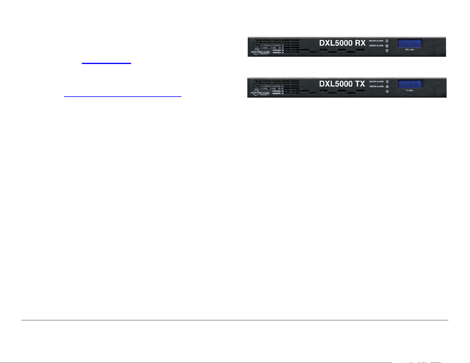
1.6.2 Configuration Descriptions
General The front panels of the DXL5000 Transmitter and
Receiver each contain three status LEDs and a 4-digit display.
DXL5000 Transmitter The rear panel of the DXL5000
Transmitter contains the I/O connectors, the AC input power
Introduction 1-2DXL5000 User and Technical Manual
Page 15
connector, and a power fuse.
• 5.925 GHz – 6.425 GHz (10MHz Channel)
DXL5000 Receiver The rear panel of the DXL5000 Receiver
contains the I/O connectors, the AC input power connector, and
a power fuse.
1.6.3 Power Options
The DXL5000 System Transmitter and Receiver each operate
on the following AC power sources:
120/240 VAC, 50/60 Hz
Fuse ratings for the AC power sources are shown in Table 1-1.
Table 1-1: Transmitter Fuse Ratings
Operating Voltage Fuse Rating
120 VAC, 50/60 Hz 3.0A, 250V, Slow Blow
240 VAC, 50/60 Hz 3.0A, 250V, Slow Blow
Table 1-2: Receiver Fuse Ratings
Operating Voltage Fuse Rating
120 VAC, 50/60 Hz 1.0A, 250V, Slow Blow
240 VAC, 50/60 Hz 1.0A, 250V, Slow Blow
• 6.425 GHz – 6.525 GHz (25MHz Channel)
• 6.525 GHz – 6.875 GHz (10MHz Channel)
• 6.875 GHz – 7.125 GHz (25MHz Channel)
• 7.1 GHz – 8.4 GHz (20MHz Channel)
• 8.2 GHz – 8.5 GHz (19MHz Channel)
• 10.7 GHz – 11.7 GHz (40MHz Channel)
• 12.2 GHz – 12.7 GHz (24MHz Channel)
• 12.7 GHz – 13.25 GHz (25MHz Channel).
1.6.5 Mounting and Deployment Options
For fixed installation applications, the DXL5000 System
Transmitter and Receiver are usually mounted in a standard 19inch (48.3 cm) rack. Power is supplied by the site or facility
power source.
For more details on installation of the DXL5000 System, see the
“Installation” Chapter on page 4-1 for additional information.
1.6.6 System Integration
Refer to the “Installation” Chapter on page 4-1 for additional
information.
1.6.4 Band and Frequency Options
The DXL5000 System can be ordered to cover the following
frequency bands.
• 1.99 GHz – 2.5 GHz (12/17MHz Channel)
• 4.94 GHz – 4.99 GHz (10MHz Channel)
Once the DXL5000 System is installed, connected, and powered
up, system settings must be selected or modified using a PC or a
laptop computer. Changes to system settings can be performed
either locally or from a remote location via an Ethernet
connection.
1.7 DXL5000 Connections
For details on connections between DXL5000 Transmitter and
Receiver components, see the “Installation” Chapter on page 4-
1.
Introduction 1-3DXL5000 User and Technical Manual
Page 16

Introduction 1-4DXL5000 User and Technical Manual
Page 17
2
Operation
2.1 Chapter Overview
This chapter provides the information that will enable you to
operate your DXL5000 Digital Microwave System (DXL5000).
Advanced Operation Procedures 2-24
User Name and Password Setup 2-24
Download New System Software 2-25
2.2 Overview of DXL5000 Transmitter
and Receiver Controls, Indicators, and
Here are the topics covered:
Topic Page
Overview of DXL5000 Transmitter and Receiver Controls, Indicators, and Connectors
DXL5000 Transmitter Controls, Indicators, and
Connectors
DXL5000 Receiver Controls, Indicators, and
Connectors
Preparing for Operation 2-5
Fixed Installation 2-5
Powering the DXL5000 System Transmitter 2-6
Powering the DXL5000 System Receiver 2-7
Initial DXL5000 System Setup 2-9
Transmitter General Procedures 2-11
Review DXL5000 System Transmitter Status 2-12
Perform DXL5000 System Transmitter Setup 2-13
Review Transmitter Alarms 2-16
Receiver General Procedures 2-18
Review DXL5000 System Receiver Status 2-19
Perform DXL5000 System Receiver Setup 2-20
Review Receiver Alarms 2-23
2-1
2-1
2-3
Connectors
This section describes the controls, indicators, and connectors
used on the DXL5000 System Transmitter and Receiver.
2.2.1 DXL5000 Transmitter Controls, Indicators, and Connectors
Controls, indicators, and connectors contained on the DXL5000
System Transmitter are shown in Figure 2-1 on page 2-2 and are
described in the following paragraphs.
TX POWER Display The TX POWER 4-digit LED display
indicates the current transmitter output power level in dBm.
MAJOR ALARM LED When flashing amber, the MAJOR
ALARM LED indicates the PA is off and the summary alarm
relay has tripped; when amber, a major alarm has been detected
but no action has been taken.
MINOR ALARM LED When green, the MINOR ALARM LED
indicates no alerts are present; when amber, indicates an alert is
present; and when red, an alert is present and the alert relay has
tripped.
SCM STATUS LED When green, the SCM STATUS LED
indicates no alarms are present; when amber, a minor alarm is
present; and when red, as major SCM alarm is present.
Operation 2-1DXL5000 User and Technical Manual
Page 18
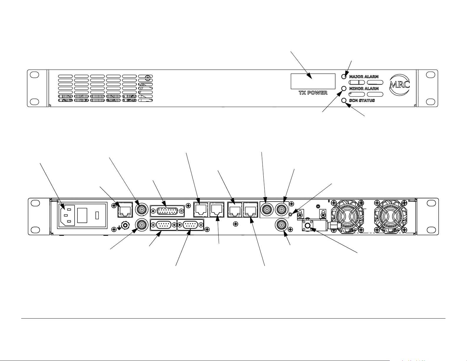
Figure 2-1: DXL5000 Transmitter Controls, Indicators, and Connectors
POWER IN
Connector
IF IN
Connector
MGMT
Connector
SUMMARY
ALARM
Connector
I
F
I
N
MGMT
I
F
M
O
N
DXL5000 TX
CHAN2 DATA
Connector
CHAN1 T1/E1
Connector
SUMMARY ALARM
CHAN2
DATA
IMC BUS WAYSIDE DATA
CHAN1
DATA
TX POWER
Display
ASI/DS3/E3 1
Connector
CHAN2
T1/E1
1
CHAN1
T1/E1
MINOR ALARM
LED
ASI/DS3/E3 2
Connector
ASI/DS3/E3
ASI/SMPTE310
2
RESET
RF OUT
MAJOR ALARM
LED
SCM STATUS
LED
RESET
Switch
IF MON
Connector
IMC BUS
Connector
WAYSIDE DATA
Connector
CHAN1 DATA
Connector
Operation 2-2DXL5000 User and Technical Manual
ASI/SMPTE310
Connector
CHAN2 T1/E1
Connector
RF OUT
Connector
Page 19

POWER IN Connector The POWER IN power connector
provides connection to the removable external power cable. The
power connector assembly also contains the AC power fuse.
ASI/SMPTE310 Connector The 75 ohm BNC female ASI/
SMPTE310 connector provides ASI or SMPTE310 inputs to the
unit.
MGMT Connector The RJ-45 MGMT connector provides 10
Base T Ethernet connection for remote control.
IF IN Connector The 75 ohm BNC female IF IN connector
provides the 70 MHz IF input to the unit.
SUMMARY ALARM Connector The DB-15 female SUMMARY
ALARM connector provides summary alarm data for common
faults and events.
CHAN1 and CHAN2 DATA Connectors The CHAN1 and
CHAN2 DATA RJ-45 connectors provide 10/100 Base T
Ethernet connections to the unit.
CHAN1 and CHAN2 T1/E1 Connectors The CHAN1 and
CHAN2 T1/E1 RJ-45 connectors provide T1/E1 input
connections for channels 1 and 2.
ASI/DS3/E3 1 and 2 Connectors The ASI/DS3/E3 1 and 2
BNC 75 ohm female connectors provide ASI or DS3/E3 inputs to
the unit.
RESET Switch When the RESET switch is pressed and held for
approximately 5 seconds, the IP address is reset to the factory
default IP address of 192.168.0.10, the subnet mask is reset to
the factory default subnet mask of 255.255.255.0, and the
default gateway is reset to the factory default subnet mask of
192.168.0.1. No other password or configuration settings are
effected.
WAYSIDE DATA Connector The WAYSIDE DATA DB-9 male
connector provides RS-232 connections for SCM operations.
IMC BUS Connector (Reserved for future use.)
IF MON Connector The 75 ohm BNC female IF MON
connector provides a 70 MHz output for external signal
monitoring purposes.
2.2.2 DXL5000 Receiver Controls, Indicators, and Connectors
Controls, indicators, and connectors contained on the DXL5000
System Receiver are shown in Figure 2-2 on page 2-4 and are
described in the following paragraphs.
RF OUT Connector The SMA 50 ohm female RF OUT
connector provides connection from the internal RF circulator to
the external antenna.
Operation 2-3DXL5000 User and Technical Manual
Page 20
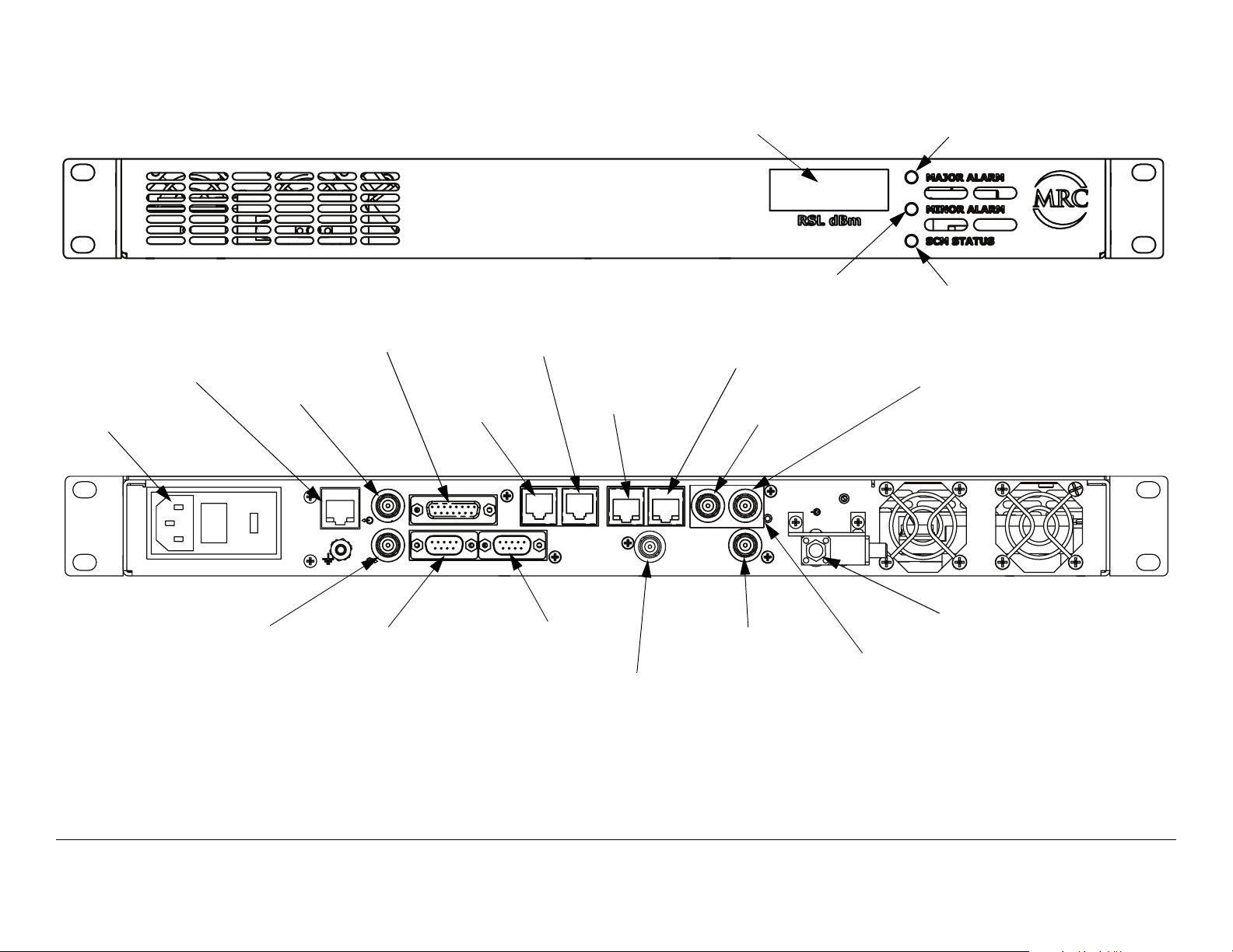
Figure 2-2: DXL5000 Receiver Controls, Indicators, and Connectors
MGMT
Connector
POWER IN
Connector
POWER IN
IF OUT
Connector
SUMMARY
ALARM
Connector
I
F
O
U
T
D
MGMT
I
V
I
N
DXL5000 RX
CHAN1
DATA
Connector
CHAN2
DATA
Connector
SUMMARY ALARM
WAYSIDE DATA
CHAN2
DATA
IMC BUS
RSL dBm
Display
CHAN1 T1/E1
Connector
CHAN1
DATA
CHAN1
T1/E1
DIV OUT
CHAN2
T1/E1
MINOR ALARM
LED
CHAN2 T1/E1
Connector
ASI/DS3/E3 1
Connector
ASI/DS3/E3
ASI/SMPTE310
2
RESET
1
MAJOR ALARM
LED
SCM STATUS
LED
ASI/DS3/E3 2
Connector
RF IN
DIV IN
Connector
WAYSIDE DATA
Connector
IMC BUS
Connector
Operation 2-4DXL5000 User and Technical Manual
DIV OUT
Connector
ASI/SMPTE310
Connector
RF IN
Connector
RESET
Switch
Page 21

RSL dBm Display The RSL dBm 4-digit LED display indicates
the current receiver signal power level in dBm.
BNC 75 ohm female connectors provide ASI or DS3/E3 outputs
from the unit.
MAJOR ALARM LED When flashing amber, the MAJOR
ALARM LED indicates the PA is off and the summary alarm
relay has tripped; when amber, a major alarm has been detected
but no action has been taken.
MINOR ALARM LED When green, the MINOR ALARM LED
indicates no alerts are present; when amber, indicates an alert is
present; and when red, an alert is present and the alert relay has
tripped.
SCM STATUS LED When green, the SCM STATUS LED
indicates no alarms are present; when amber, a minor alarm is
present; and when red, as major SCM alarm is present.
POWER IN Connector The POWER IN power connector
provides connection to the removable external power cable. The
power connector assembly also contains the AC power fuse.
MGMT Connector The RJ-45 MGMT connector provides 10
Base T Ethernet connection for remote control.
IF OUT Connector The 75 ohm BNC female IF OUT connector
provides the 70 MHz IF output from the unit.
SUMMARY ALARM Connector The DB-15 SUMMARY
ALARM female connector provides summary alarm data for
common faults and events.
RF IN Connector The SMA 50 ohm female RF IN connector
provides the 70 MHz input from the external antenna.
RESET Switch When the RESET switch is pressed and held for
approximately 5 seconds, the IP address is reset to the factory
default IP address of 192.168.0.10, the subnet mask is reset to
the factory default subnet mask of 255.255.255.0, and the
default gateway is reset to the factory default subnet mask of
192.168.0.1. No other password or configuration settings are
effected.
ASI/SMPTE310 Connector The 75 ohm BNC female ASI/
SMPTE310 connector provides ASI or SMPTE310 outputs from
the unit.
DIV OUT Connector The 75 ohm BNC female DIV OUT
connector provides the diversity receive output from the unit.
IMC BUS Connector The IMC BUS DB-9 male connector
provides RS-232 or RS-485 inputs to the unit.
WAYSIDE DATA Connector The WAYSIDE DATA DB-9 male
connector provides connections for MPEG decoder Wayside
data.
DIV IN Connector The 75 ohm BNC female DIV IN connector
provides the diversity receive input to the unit.
CHAN1 and CHAN2 DATA Connectors The CHAN1 and
CHAN2 DATA RJ-45 connectors provides 10/100 Base T
Ethernet connections to the unit.
CHAN1 and CHAN2 T1/E1 Connectors The CHAN1 and
CHAN2 T1/E1 RJ-45 connectors provide T1/E1 output
connections for channels 1 and 2.
ASI/DS3/E3 1 and 2 Connectors The ASI/DS3/E3 1 and 2
2.3 Preparing for Operation
Each installation or deployment will have its own specific tasks
according to the application and the installed hardware.
2.3.1 Fixed Installation
For fixed installations, the DXL5000 System is typically mounted
Operation 2-5DXL5000 User and Technical Manual
Page 22

in a standard 19-inch (48.3 cm) rack. The cabling is permanently
installed and power comes from the facility or site power source.
Each installation will have its own specific tasks according to the
application and the installed hardware options.
For installation information, refer to the “Installation” section on
page 4-1.
2.3.2 Powering the DXL5000 System Transmitter
CAUTION
Corruption of software contained in the
DXL5000 System Transmitter may occur if
proper power down or power up of the
DXL5000 does not occur.
The software will become corrupted and the
DXL5000 System Transmitter may have to
be returned to the factory for repair.
CAUTION
Note
If power is accidentally lost, do not
immediately re-apply power to the DXL5000
System Transmitter.
Internal software corruption may occur if
power is applied immediately after a power
loss.
To avoid possible software corruption, wait a
minimum of 10 seconds before re-applying
power.
If you are unsure of the power requirements or
connections to the DXL5000 System Transmitter,
refer to the “Installation” section on page 4-1 .
The DXL5000 System Transmitter must be properly powered up
and powered down to prevent possible corruption of the software
contained in the radio. It will take approximately 30 seconds for
the DXL5000 System Transmitter to initialize.
Power to the DXL5000 System Transmitter must never be cycled
off and on without a minimum delay of 10 seconds between
removal of power and application of power.
Conversely, power to the DXL5000 System Transmitter must
never be cycled to on and then immediately to off, as corruption
of software contained in the radio may also occur.
Power Up
The steps required to properly power up the DXL5000 System
Transmitter are contained in the following steps.
Operation 2-6DXL5000 User and Technical Manual
Note
1. Verify the power cable is properly connected to the
When the DXL5000 System Transmitter is
powered up, it will automatically return to the last
settings that were in use when the unit was
powered down.
The unit will also resume transmitting if the unit
was transmitting when it was powered down, as
long as there are no alarms preventing
transmitting.
DXL5000 System Transmitter rear panel AC POWER
IN connector.
Page 23

CAUTION
In the following step, ensure cable
connections to the RF OUT are properly
connected.
Failure to connect the system to the RF
OUT connector could damage the loads on
the circulators.
2. Verify all coaxial cables and cable connectors are
properly connected to the rear panel connectors, as
applicable to your system options.
7. Press the PC/laptop Enter key, and observe the
DXL5000 Log In window is displayed.
8. Enter your user name and password in the User
Name and Password text boxes and select the Log
In option button.
9. Observe the Status page Identification tab is
displayed.
Power Down
The steps required to properly power down the DXL5000 System
Transmitter are contained in the following steps.
1. Select the Log Out tab and observe the Log In screen
is displayed.
Note
3. Set the facility power source to on.
4. Verify the PC/laptop to be used to locally or remotely
5. Open Windows Internet Explorer®.
Note
6. Enter the DXL5000 System Transmitter IP address as
The DXL5000 System Transmitter does not
contain a power switch. When facility power is
applied to the DXL5000 System Transmitter, the
unit will power up.
control the DXL5000 System Transmitter is powered
up and is connected to the MGMT RJ-45 rear panel
connector, either directly or via the internet.
In the following step, xxx.xxx.xxx.xxx is the IP
address.
follows:
http//xxx.xxx.xxx.xxx
2. Remove facility power from the DXL5000 System
Transmitter.
2.3.3 Powering the DXL5000 System Receiver
CAUTION
The DXL5000 System Receiver must be properly powered up
and powered down to prevent possible corruption of the software
contained in the radio. It will take approximately 30 seconds for
the DXL5000 System Receiver to initialize.
Power to the DXL5000 System Receiver must never be cycled
Corruption of software contained in the
DXL5000 System Receiver may occur if
proper power down or power up of the
DXL5000 does not occur.
The software will become corrupted and the
DXL5000 System Receiver may have to be
returned to the factory for repair.
Operation 2-7DXL5000 User and Technical Manual
Page 24

off and on without a minimum delay of 10 seconds between
removal of power and application of power.
Conversely, power to the DXL5000 System Receiver must never
be cycled to on and then immediately to off, as corruption of
software contained in the radio may also occur.
Power Up
1. Verify the power cable is properly connected to the
DXL5000 System rear panel AC POWER IN
connector.
2. Verify all coaxial cables and cable connectors are
properly connected to the rear panel connectors, as
applicable to your system options.
The steps required to properly power up the DXL5000 System
Receiver are contained in the following steps.
CAUTION
If power is accidentally lost, do not
immediately re-apply power to the DXL5000
System Receiver.
Internal software corruption may occur if
power is applied immediately after a power
loss.
To avoid possible software corruption, wait a
minimum of 10 seconds before re-applying
power.
Note
Note
If you are unsure of the power requirements or
connections to the DXL5000 System Receiver,
refer to the “Installation” section on page 4-1 .
When the DXL5000 System Receiver is powered
up, it will automatically return to the last settings
that were in use when the unit was powered down.
Note
3. Set the facility power source to on.
4. Verify the PC/laptop to be used to locally or remotely
5. Open Windows Internet Explorer®.
Note
6. Enter the DXL5000 System Receiver IP address as
7. Press the PC/laptop Enter key, and observe the
8. Enter your user name and password in the User
9. Observe the Status page Identification tab is
The DXL5000 System Receiver does not contain a
power switch. When facility power is applied to the
DXL5000 System Receiver, the unit will power up.
control the DXL5000 System Receiver is powered up
and is connected to the MGMT RJ-45 rear panel
connector, either directly or via the internet.
In the following step, xxx.xxx.xxx.xxx is the IP
address.
follows:
http//xxx.xxx.xxx.xxx
DXL5000 Log In window is displayed.
Name and Password text boxes and select the Log
In option button.
displayed.
Operation 2-8DXL5000 User and Technical Manual
Page 25

Power Down
The steps required to properly power down the DXL5000 System
Receiver are contained in the following steps.
1. Select the Log Out tab and observe the Log In screen
is displayed.
2. Remove facility power from the DXL5000 System
Receiver.
2.4 Initial DXL5000 System Setup
To log into the DXL5000 System Transmitter or Receiver
software for the System Administrator to set up IP, Subnet Mask,
and Default Gateway addresses, see Figure 2-3 on page 2-10.
Operation 2-9DXL5000 User and Technical Manual
Page 26

Figure 2-3: Initial Setup
Verify DXL5000 System
Transmitter/Receiver is
powered up
Enter admin
in Password:
text box
Select Log In
option button
Open Windows
Internet Explorer
Select Setup Tab
Enter factory
default IP
address
(192.168.0.10)
Note:
The factory default User
Name and Password is
admin.
Select
Identification
Tab
Log In screen is
displayed
Select Submit
option button and
power-cycle radio
Enter admin
in User Name:
text box
Perform “Review
Transmitter Alarms” on
page 2-16
IP Address:
Enter new IP
Address, as
required
Subnet Mask:
Enter new Subnet
Mask address, as
required
Operation 2-10DXL5000 User and Technical Manual
Default Gateway:
Enter new Default
Gateway
address, as
required
Note:
After setting addresses, the
Submit option button must be
selected and the radio power
must be cycled from on to off.
The radio does not need to be
power-cycled when other
options are changed.
Page 27

2.5 Transmitter General Procedures
To log into the DXL5000 System Transmitter software to review
system status, to select transmitter settings, to review alarms,
and to log out of the DXL5000 System Transmitter, see Figure 2-
4.
After logging in, you will have access to the Status, Setup,
Administration, Alarms, Downloads, and Log Out tabs.
•The Status tab displays information about general
settings and the status of the system.
•The Setup tab allows you to change or edit system
parameters.
Figure 2-4: DXL5000 Transmitter Top Level Hierarchy
•The Administration tab allows the System Administrator
to change user names and passwords.
•The Alarms tab displays system alarm status and
provides you with the ability to re-classify the severity of
errors to their own custom settings.
•The Downloads tab allows the System Administrator to
download updated software into the radio.
•The Log Out tab allows you to log out of the web
interface.
Verify DXL5000 System
Transmitter is powered up
Select Log In
option button
Status Tab
Open Windows
Internet Explorer
Setup Tab
Enter IP address
Administration
Tab
Log In screen is
displayed
Alarms Tab
User Name:
Enter user name
required.
Downloads Tab
Log Out Tab
Password:
Enter password
required
Operation 2-11DXL5000 User and Technical Manual Operation 2-11DXL5000 User and Technical Manual
Page 28

2.5.1 Review DXL5000 System Transmitter Status
To review the current DXL5000 System Transmitter status,
Figure 2-5: Status Tab Options - Typical
Select Status Tab
select the Status tab and then select the Identification tab,
Monitor Radio tab, Firmware Revisions, or Monitor Mod tab,
as required. See Figure 2-5.
Select Help Tab
IP Address: XXX.XXX.X.XX
Subnet Mask: YYY.YYY.YYY.Y
Default Gateway: ZZZ.ZZZ.Z.Z
Serial Number: 1234567890
Software Version: X.Y.Z
Site Name: XXXXX
Call Sign: YYYY
Date Installed: MM/DD/YY
User Information 1: XXX
User Information 2: YYY
User Information 3: ZZZ
Select Identification
Tab
Select Monitor
Radio Tab
Operating Frequency: XXXX.XX MHz
RF Output Power: 32.0 dBm
PA Voltage: 12.1
+15V: 14.9
-15V: -15.1
+5V: 4.9
System Temp: 0.0
Power Amplifier: ON
Test Tone: OFF
Select Firmware
Revisions Tab
System Software: 0.50 (Build 26)
SCM PC FPGA: 3.0.0
SCM PC uP: 3.0.1
SCD PC FPGA: NA
SCD uP: NA
Radio Type: DXL 5000 Tx
Select Monitor Mod
Tab
Symbol Rate: 20.000 Msps
Modulation: QPSK
Percent Utilization: 0.00%
Core Channel 1: none at 0.000 Mbps
Core Channel 2: none at 0.000 Mbps
Core Channel 3: none at 0.000 Mbps
Core Channel 4: none at 0.000 Mbps
Invert Spectrum: OFF
PRBS: OFF
Operation 2-12DXL5000 User and Technical Manual Operation 2-12DXL5000 User and Technical Manual
Page 29

2.5.2 Perform DXL5000 System Transmitter Setup
To set up DXL5000 System Transmitter operating settings, first
Figure 2-6: Setup Tab Options - Sheet 1
Select Setup Tab
select the Setup tab and then select the Identification tab,
Radio tab, and Modulator tab, as required. See Figure 2-6.
Select Help Tab
IP Address:
Enter new IP
Address, as
required
Note:
After setting addresses, the Submit
option button must be selected and the
radio power must be cycled from on to
off. The radio does not need to be
power-cycled when other options are
changed.
Select
Identification
Tab
Subnet Mask:
Enter new
Subnet Mask
address, as
required
Default Gateway:
Enter new
Default Gateway
address, as
required
Select Submit
option button and
power-cycle radio
Select Power Amplifier
On or Off radio button,
as required
Site Name:
Enter Site Name,
as required
Note:
Select the Submit option button to send
settings to the radio or select the Reset
option button to clear the current
settings on the individual tabs.
Call Sign:
Enter Call Sign,
as required
Select Radio Tab
Select Test Tone On
or Off radio button, as
required
Date Installed:
Enter Date
Installed, as
required
To Figure 2-7
A
on page 2-14
Select IF Input Internal
or External radio
button, as required
User
Information 1
Enter data, as
required
Select Submit
option button
User
Information 2
Enter data, as
required
User
Information 3
Enter data, as
required
Select Submit
option button
Operation 2-13DXL5000 User and Technical Manual Operation 2-13DXL5000 User and Technical Manual
Page 30

Figure 2-7: Setup Tab Options - Sheet 2
From
Figure 26 on
A
Select Modulator
Tab
page 2-13
Note
The Invert Spectrum - On radio button
should be selected only in the event the
incoming signal becomes inverted due to
a device or event in the signal path.
Symbol Rate:
Enter Symbol
Rate (range is
3.0 to 20.0) or
accept default
rate, as required
Modulation:
Select
Modulation
menu option
required. Options
are QPSK,
16QAM, 32QAM,
64QAM, QPSK
1/2, QPSK 2/3,
QPSK 3/4, QPSK
5/6, QPSK 7/8,
16QAM 1/2,
16QAM 3/4,
64QAM 2/3,
64QAM 3/4,
64QAM 5/6, or
64QAM 7/8
Core Channel X:
B
To Figure 2-8
on page 2-15
Invert Spectrum PRBS
Select On or Off
option button , as
required
CAUTION
The PRBS – On radio button should be
selected only for system setup or
troubleshooting. For normal operation,
the PRBS – Off radio button must be
selected.
Selection of the PRBS – On radio option
button will result in loss of the broadcast
signal.
Select On or Off
option button , as
required
Select Submit
option button
Setup is complete
Operation 2-14DXL5000 User and Technical Manual
Page 31

Figure 2-8: Setup Tab Options - Sheet 3
From
Figure 2-7
on page 214
B
Select Core
Channel X: ASI
BNC-1, ASI
BNC-2, or ASI
BNC-3, as
required
Enter ASI Data
Rate required
(range is 0.064 to
90.0 Mbps)
Select Core
Channel menu
option required
Select Core
Channel X: DS3
BNC-1, DS3
BNC-2, E3 BNC1, or E3 BNC-2,
as required
DS3 Data Rate is
fixed (44.7360
Mbps).
E3 Data Rate is
fixed (34.3680
Mbps)
Select Cable
Length: menu
option, as
required. Options
are Under 255
feet or Over 255
feet
Notes:
When selecting Core Channel inputs, only one connector may be
selected at a time.
For example, ASI BNC-1 and DS3 BNC-1 cannot be selected for two
Core Channel inputs. The radio BNC-1 connector can only be used
for one Core Channel input.
Core Channel X represents Core Channels 1 thru 4. Select input
options, or the none option, for Core Channel 1 thru 4, as required.
Select Core
Channel X:
SMPTE BNC-3,
as required
SMPTE Data
Rate is fixed
(19.392658
Mbps)
Select Core
Channel X: T1
RJ45-1 or T1
RJ45-2 option, as
required
T1 Data Rate is
fixed (1.544
Mbps)
Select LBO:
menu option, as
required. Options
are -30 or -36
Select Channel
Coding: menu
option, as
required. Options
are Enabled or
Disabled
Select Core
Channel X: E1
RJ45-1 or E1
RJ45-2 option, as
required
E1 Data Rate is
fixed (2.048
Mbps)
Select LBO:
menu option, as
required. Options
are -12 or -43
Select Channel
Coding: menu
option, as
required. Options
are Enabled or
Disabled
Note
When selecting Modulation, Core
Channel 1 thru 4, and Data Rates, the
Utilization indication must not exceed
100%.
Select Core
Channel X:
Ethernet RJ45-1
option, as
required
Enter Data Rate
required (range is
0.064 to 90.0
Mbps)
Select Mode:
menu option, as
required. Options
are 10 Mb/sec,
100 Mb/s, or
auto
Select Duplex:
menu option, as
required. Options
are Full or Half
Select Core
Channel X:
RS232 or RS485
option, as
required
Enter Data Rate
required (must
match Baud
Rate)
Select Baud
Rate: menu
option, as
required. Options
are 600, 1200,
2400, 4800,
9600, 14400,
19200, 28822,
38600, 52600,
115200, or
230400
Select Core
Channel X: none
option, as
required
Select
Termination:
menu option, as
required. Options
are 75 Ohm, 100
Ohm, or 120
Ohm
Operation 2-15DXL5000 User and Technical Manual
Select
Termination:
menu option, as
required. Options
are 75 Ohm, 100
Ohm, or 120
Ohm
Select Chain
LIU: menu
option, as
required. Options
are Enabled or
Disabled
Page 32

2.5.3 Review Transmitter Alarms
To review DXL5000 System Transmitter alarms and to set up
alarm monitoring options, see Figure 2-9. To review current
Figure 2-9: Review Alarms - Sheet 1
Note:
Each of the Information tab status options may be
configured using the corresponding Configure option
button. Select the corresponding Configure option
button for each status option, as required.
alarm status, select the Alarm tab and then select the
Information tab. To set alarm monitoring options, select the
Configure option button for the corresponding status option.
Select Alarms Tab
PLL Status:
Observe PLL
Status
Indication
Select Help Tab
Fan:
Observe
Fan status
indication
Power
Supply:
Observe
Power
Supply status
indication
PA Voltage:
Observe PA
Voltage:
status
Calc:
Observe
Calc status
ASI BNC1:
Observe ASI
BNC1 status
Code:
Observe
Code status
ASI BNC2:
Observe ASI
BNC2 status
Select
Information Tab
CH0 FIFO:
Observe
CH0 FIFO
status
ASI BNC3:
Observe ASI
BNC3 status
CH1 FIFO:
Observe
CH1 FIFO
status
T1 RJ45-1
Observe T1
RJ45-1
status
CH2 FIFO:
Observe
CH2 FIFO
status
Select Configure
option button, as
required
Select Log Tab
CH3 FIFO:
Observe
CH3 FIFO
status
RF Out:
Observe RF
Output
status
To Figure 2-10
A
on page 2-17
Observe current
Alarm history
IF Input:
Observe IF
Input status
Operation 2-16DXL5000 User and Technical Manual Operation 2-16DXL5000 User and Technical Manual
Page 33

Figure 2-10: Review Alarms - Sheet 2
From
Figure 2-9 on
page 2-16
A
Status options
displayed
Status Options - Typical
Select Severity
Major, Minor, or
Disabled radio
button option, as
required
Select Type
Alarm or Alert
radio button
option, as
required
Select Latch On
or Off radio
button option, as
required
Select Save
option button
Note:
When the Save option button is
selected, the Severity, Type, and
Latch options will be entered into
the radio software.
If changes have been made to the
Severity, Type, or Latch options,
selecting the Quit option button
will cancel the changes to the
Severity, Type, and/or Latch
options.
Operation 2-17DXL5000 User and Technical Manual
Page 34

2.6 Receiver General Procedures
To log in to the DXL5000 System Receiver software to review
system status, to select receiver settings, to review alarms, and
to log out of the DXL5000 System Receiver, see Figure 2-11.
After logging in, you will have access to the Status, Setup,
Administration, Alarms, Downloads, and Log Out tabs.
•The Status tab displays information about general
settings and the status of the system.
•The Setup tab allows you to change or edit system
parameters.
Figure 2-11: DXL5000 Receiver Top Level Hierarchy
•The Administration tab allows the System Administrator
to change user names and passwords.
•The Alarms tab displays system alarm status and
provides you with the ability to re-classify the severity of
errors to their own custom settings.
•The Downloads tab allows the System Administrator to
download updated software into the radio.
•The Log Out tab allows you to log out of the web
interface.
Verify DXL5000 System
Receiver is powered up
Select Log In
option button
Status Tab
Open Windows
Internet Explorer
Setup Tab
Enter IP address
Administration
Tab
Log In screen is
displayed
Alarms Tab
User Name:
Enter user name
required.
Downloads Tab
Log Out Tab
Password:
Enter password
required
Operation 2-18DXL5000 User and Technical Manual Operation 2-18DXL5000 User and Technical Manual
Page 35

2.6.1 Review DXL5000 System Receiver Status
To review the current DXL5000 System Receiver status, first
Figure 2-12: Status Tab Options - Typical
Select Status Tab
select the Status tab and then select the Identification tab,
Monitor Radio Tab, Firmware Revisions tab, or Monitor
Demod tab, as required. See Figure 2-12.
Select Help Tab
IP Address: XXX.XXX.X.XX
Subnet Mask: YYY.YYY.YYY.Y
Default Gateway: ZZZ.ZZZ.Z.Z
Serial Number: 1234567890
Software Version: X.Y.Z
Site Name: XXXXX
Call Sign: YYYY
Date Installed: MM/DD/YY
User Information 1: XXX
User Information 2: YYY
User Information 3: ZZZ
Select Identification
Tab
Select Monitor
Radio Tab
Operating Frequency: XXXX.XX MHz
RSL Input Power: 32.0 dBm
+12V: 12.1
+15V: 14.9
-15V: -15.1
+5V: 4.9
System Temp: 0.0
Select Firmware
Revisions Tab
System Software: 0.XX
SCM PC FPGA: N/A
SCM PC uP: N/A
SCD PC FPGA: 3.0.0
SCD PC uP: 3.0.1
Radio Type: DXL5000 Rx
Symbol Rate: 20.0 Msps
Modulation: QPSK
Percent Utilization: 50.00%
Core Channel 1: none at 0.000 Mbps
Core Channel 2: none at 0.000 Mbps
Core Channel 3: none at 0.000 Mbps
Core Channel 4: none at 0.000 Mbps
Invert Spectrum: OFF
PRBS: OFF
SNR: 0.00 dB
EVM: 0.0%
Select Monitor
Demod Tab
Operation 2-19DXL5000 User and Technical Manual Operation 2-19DXL5000 User and Technical Manual
Page 36

2.6.2 Perform DXL5000 System Receiver Setup
To set up the DXL5000 Receiver operating settings, first select
Figure 2-13: Setup Tab Options - Sheet 1
Select Setup Tab
the Setup tab and then select the Identification tab and
Demodulator tab, as required. See Figure 2-13.
To Figure 2-14 on
A
page 2-21
Select Help Tab
IP Address:
Enter new IP
Address, as
required
Note:
After setting addresses, the Submit
option button must be selected and the
radio power must be cycled from on to
off. The radio does not need to be
power-cycled when other options are
changed.
Subnet Mask:
Enter new
Subnet Mask
address, as
required
Default Gateway:
Enter new
Default Gateway
address, as
required
Select Submit
option button and
power-cycle radio
Select
Identification
Tab
Site Name:
Enter Site Name,
as required
Note:
Select the Submit option button to send
settings to the radio or select the Reset
option button to clear the current
settings on the individual tabs.
Call Sign:
Enter Call Sign,
as required
Date Installed:
Enter Date
Installed, as
required
User
Information 1
Enter data, as
required
User
Information 2
Enter data, as
required
User
Information 3
Enter data, as
required
Select Submit
option button
Operation 2-20DXL5000 User and Technical Manual Operation 2-20DXL5000 User and Technical Manual
Page 37

Figure 2-14: Setup Tab Options - Sheet 2
From Figure 2-13
on page 2-20
A
Select
Demodulator Tab
Note
The Invert Spectrum - On radio button
should be selected only in the event the
incoming signal becomes inverted due to
a device or event in the signal path.
Enter Symbol
Rate (range is
3.0 to 20.2) or
accept default
rate, as required
Modulation:Symbol Rate:
Select
Modulation
menu option
required. Options
are QPSK,
16QAM, 32QAM,
64QAM, QPSK
1/2, QPSK 2/3,
QPSK 3/4, QPSK
5/6, QPSK 7/8,
16QAM 1/2,
16QAM 3/4,
64QAM 2/3,
64QAM 3/4,
64QAM 5/6, or
64QAM 7/8
Core Channel X:
B
To Figure 2-15
on page 2-22
Invert Spectrum
Select On or Off
option button , as
required
Select Submit
option button
Setup is complete
Operation 2-21DXL5000 User and Technical Manual
Page 38

Figure 2-15: Setup Tab Options - Sheet 3
From
Figure 2-14
on page 221
B
Select Core
Channel X: ASI
BNC-1, ASI
BNC-2, or ASI
BNC-3, as
required
Enter Data Rate
required (range is
0.064 to 90.0
Mbps)
Select Core
Channel menu
option required
Select Core
Channel X: DS3
BNC-1, DS3
BNC-2, E3 BNC1, or E3 BNC-2,
as required
DS3 Data Rate is
fixed (44.7360
Mbps).
E3 Data Rate is
fixed (34.3680
Mbps)
Select Cable
Length: menu
option, as
required. Options
are Under 255
feet or Over 255
feet
Notes:
When selecting Core Channel outputs, only one connector may be
selected at a time.
For example, ASI BNC-1 and DS3 BNC-1 cannot be selected for two
Core Channel outputs. The radio BNC-1 connector can only be used
for one Core Channel output.
Core Channel X represents Core Channels 1 thru 4. Select output
options, or the none option, for Core Channel 1 thru 4, as required.
Select Core
Channel X:
SMPTE BNC-3,
as required
SMPTE Data
Rate is fixed
(19.392658
Mbps)
Select Core
Channel X: T1
RJ45-1 or T1
RJ45-2 option, as
required
Ti Data Rate is
fixed (1.544
Mbps)
Select LBO:
menu option, as
required. Options
are -30 or -36
Select Channel
Coding: menu
option, as
required. Options
are Enabled or
Disabled
Select Core
Channel X: E1
RJ45-1 or E1
RJ45-2 option, as
required
E1 Data Rate is
fixed (2.048
Mbps)
Select LBO:
menu option, as
required. Options
are -12 or -43
Select Channel
Coding: menu
option, as
required. Options
are Enabled or
Disabled
Note
When selecting Modulation, Core
Channel 1 thru 4, and Data Rates, the
Utilization indication should be as close
to 100% as possible.
Select Core
Channel X:
Ethernet RJ45-1
option, as
required
Enter Data Rate
required (range is
0.064 to 90.0
Mbps)
Select Mode:
menu option, as
required. Options
are 10 Mb/sec,
100 Mb/s, or
auto
Select Duplex:
menu option, as
required. Options
are Full or Half
Select Core
Channel X:
RS232 or RS485
option, as
required
Enter Data Rate
required (must
match Baud
Rate)
Select Baud
Rate: menu
option, as
required. Options
are 600, 1200,
2400, 4800,
9600, 14400,
19200, 28822,
38600, 52600,
115200, or
230400
Select Core
Channel X: none
option, as
required
Select
Termination:
menu option, as
required. Options
are 75 Ohm, 100
Ohm, or 120
Ohm
Operation 2-22DXL5000 User and Technical Manual
Select
Termination:
menu option, as
required. Options
are 75 Ohm, 100
Ohm, or 120
Ohm
Select Chain
LIU: menu
option, as
required. Options
are Enabled or
Disabled
Page 39

2.6.3 Review Receiver Alarms
To review DXL5000 System Receiver alarms and to setup alarm
Figure 2-16: Review Alarms
Select Help Tab
Note:
Each of the Information tab status
options may be configured using the
corresponding Configure option
button. Select the corresponding
Configure option button for each
status option, as required.
monitoring options, see Figure 2-16. To review current alarm
status, first select the Alarm tab and then select the Information
tab. To select alarm monitoring options, select the Configure
option button for the corresponding status option.
Select Alarms Tab
Select
Information Tab
Select Log Tab
Observe current
Alarm history
Note:
When the Save option button is selected, the
Severity, Type, and Latch options will be
entered into the radio software.
If changes have been made to the Severity,
Type, or Latch options, selecting the Quit
option button will cancel the changes to the
Severity, Type, and/or Latch options.
PLL Status:
Observe PLL
Status
Indication
Carrier:
Observe
Carrier
status
Power
Supply:
Observe
Power
Supply
status
SCD CH0:
Observe
SCD CH0
status
Calc:
Observe
Calc status
SCD CH1:
Observe
SCD CH1
status
Code:
Observe
Code status
SCD CH2:
Observe
SCD CH2
status
CH0 FIFO:
Observe
CH0 FIFO
status
SCD CH3:
Observe
SCD CH3
status
Status Options - Typical
CH1 FIFO:
Observe
CH1 FIFO
status
Select Configure
option button, as
required
Operation 2-23DXL5000 User and Technical Manual Operation 2-23DXL5000 User and Technical Manual
CH2 FIFO:
Observe
CH2 FIFO
status
CH3 FIFO:
Observe
CH3 FIFO
status
Status options
displayed
Select Severity
Major, Minor, or
Disabled radio
button option, as
required
RSL:
Observe
RSL status
Select Type
Alarm or Alert
radio button
option, as
required
Fade Margin:
Observe
Fade
Margin
status
Select Latch On
or Off radio
button option, as
required
Select Save
option button
Page 40

2.7 Advanced Operation Procedures
2.7.1 User Name and Password Setup
The procedures required to assign user names and passwords
and to download new software into either the DXL5000
Transmitter or Receiver are contained in the following
paragraphs. These procedures are generic to both the
Transmitter and Receiver.
Figure 2-17: User Name and Password Setup
Administration Tab
Help Tab
User Accounts
Tab
To set up the DXL5000 Transmitter and/or Receiver users and
passwords, see Figure 2-17. This procedure may only be
performed by the system administrator.
To set up user names and passwords, select the Administration
tab, select the User Accounts tab, and then select the
applicable user to be added, changed, or deleted.
Notes:
The Administration tab is displayed only if the Administrator has logged into the
radio. Only the Administrator may add, change, or delete users.
When the Submit option button is selected, the User Name and Password will
be entered into the radio software.
If changes have been made to either a User Name or Password, selecting the
Reset option button will cancel the changes to the User Name and Password.
To delete a user, select the Delete option button.
User Name:
Enter
Administrator
user name
Administrator
Enter
Administrator
password
Select Submit
option button
Password:
User 1 User 2 User 3 User 4
User Name: User Name: User Name: User Name:Password: Password: Password: Password:
Enter User 1 user
name
Select Submit
option button
Enter User 1
password
Enter User 2 user
name
Select Submit
option button
Enter User 2
password
Enter User 3 user
name
Select Submit
option button
Enter User 3
password
Enter User 4 user
name
Select Submit
option button
Enter User 4
password
Operation 2-24DXL5000 User and Technical Manual Operation 2-24DXL5000 User and Technical Manual
Page 41

2.7.2 Download New System Software
To load new software into the DXL5000 System Transmitter, the
Figure 2-18: Downloads Tab Options
CAUTION
In the event of a power failure during the software upgrade
process, the DXL5000 software can be erased.
It is recommended that the software upgrade be performed
using an uninterruptible power supply.
Downloads tab must be selected. See Figure 2-18. This
procedure may only be performed by the System
Administrator.
Notes:
Software upgrade files must be obtained from the
factory prior to performing this procedure. The
software upgrade file(s) should be stored on your PC
hard drive.
Only use a valid upgrade file provided by the factory.
Failure to use factory-provided upgrade software can result
in damage to the equipment
Verify DXL5000 System
Transmitter/Receiver is
powered up
Enter password
in Password:
text box
When Firmware
File is selected,
select Upgrade
option button
Open Windows
Internet Explorer
Select Log In
option button
When upgrade is
complete, select
Log Out tab
Only the System Administrator may perform this
procedure.
Enter IP address
Select
Downloads Tab
Download
procedure is
complete. Return
to normal
operation
Log In screen is
displayed
Select
Software Tab
Enter user name
in User Name
text box
Select Browse
option button and
select the
required
Firmware File
Operation 2-25DXL5000 User and Technical Manual Operation 2-25DXL5000 User and Technical Manual
Page 42

Operation 2-26DXL5000 User and Technical Manual
Page 43

3
Troubleshooting
3.1 Chapter Overview
This chapter describes how to troubleshoot your DXL5000
Digital Microwave System (DXL5000) Transmitter and Receiver.
3.2 Errors/Alarms
Errors detected during normal operation of the DXL5000 System
Transmitter or Receiver will cause the front panel MAJOR
ALARM, MINOR ALARM, or SCM STATUS LED indicators to
turn amber or red to alert you to investigate the problem. See
Figure 3-1.
Figure 3-1: Alarm Indicators- Typical
as major SCM alarm is present.
Individual alarms are shown on the Alarms - Information tab
displayed on your PC or laptop when you are connected to the
rear panel MGMT connector, either directly or via the internet.
Note that alarms presented in this chapter reflect the factory
default alarm Severity and Type settings. The alarm Severity
level and Typ e settings may be changed by performing “Review
Transmitter Alarms” on page 2-16 to change the settings for an
alarm. See Figure 3-2 on page 3-2.
In Figure 3-2 on page 3-2, no alarms are present, the status for
each option indicates OK in green font, and the Summary
Alarm option button label indicates OK with a green
background. If major or minor faults are present, the option
status will indicate Fault in either red or amber font and the
Summary Alarm option button label will indicate Major or Minor
with a red or amber background, respectively.
If the Latch - On option is selected, you are alerted to the fact
that an error has occurred, even if the fault has been corrected.
When the On option is selected, the alarm must be
acknowledged using the Summary Alarm option button to clear
the alarm. If the Latch - Off option is selected, the alarm will
automatically reset when the fault is corrected.
When flashing amber, the MAJOR ALARM LED indicates the
PA is off and the summary alarm relay has tripped; when amber,
a major alarm has been detected but no action has been taken.
When green, the MINOR ALARM LED indicates no alerts are
present; when amber, indicates an alert is present; and when
red, an alert is present and the alert relay has tripped.
When green, the SCM STATUS LED indicates no alarms are
present; when amber, a minor alarm is present; and when red,
Troubleshooting 3-1DXL5000 User and Technical Manual
To review a log of all alarms, select the Alarms - Log tab.
See Table 3-1 on page 3-3 for a list of Transmitter alarms and
what to do when they appear. See Table 3-2 on page 3-4 for a
list of Receiver alarms and what to do when they appear.
Page 44

Figure 3-2: Alarms Tab - Typical
Troubleshooting 3-2DXL5000 User and Technical Manual
Page 45

Table 3-1: Default Transmitter Alarms
Error Message Error Type Suggested Technical Staff Action
Power Supply Major • Indicates internal power supply fault and potential unstable operation.
Verify input power is correct.
• Call MRC Technical Support.
PLL Major Local oscillator is unlocked
Fan Minor • System fan(s) not operating or not operating at correct speed.
• Call MRC Technical Support.
RF Out Major PF power output is too low
IF Input Major IF input is too low
PA Voltage Major PA voltage is out of range
ASI0 LOS Major ASI interface error
ASI1 LOS Major ASI interface error
ASI2 LOS Major ASI interface error
T1/E1 LOS Minor DS3 interface error
T1/E1 LOS Minor DS3 interface error
ETH0 LOS Minor Ethernet error
ETH1 LOS Minor Ethernet error
T1/E1 0 LOS Minor T1 interface error
T1/E1 1 LOS Minor T1 interface error
SMPTE LOS Major SMPTE interface error
SMPTE PLL Major SMPTE interface error
RS232 LOS Minor RS232 interface error
RS485 LOS Minor RS485 interface error
CH0 FIFO Overflow Major/SCM Data FIFO error
CH1 FIFO Overflow Major/SCM Data FIFO error
Troubleshooting 3-3DXL5000 User and Technical Manual
Page 46

Table 3-1: Default Transmitter Alarms (Continued)
Error Message Error Type Suggested Technical Staff Action
CH0 FIF2 Overflow Major/SCM Data FIFO error
CH0 FIF3 Overflow Major/SCM Data FIFO error
CH0 FIFO Underflow Minor/SCM Data FIFO error
CH1 FIFO Underflow Minor/SCM Data FIFO error
CH0 FIF2 Underflow Minor/SCM Data FIFO error
CH0 FIF3 Underflow Minor/SCM Data FIFO error
CALC Error Major/SCM SCM internal error
Invalid Authen Code Error Minor/SCM SCM invalid license code
Table 3-2: Default Receiver Alarms
Error Message Error Type Suggested Technical Staff Action
Power Supply Major • Indicates internal power supply fault and potential unstable operation.
Verify input power is correct.
• Call MRC Technical Support.
PLL Major Local oscillator is unlocked
Fan Minor • System fan(s) not operating or not operating at correct speed.
Call MRC Technical Support.
RSL Error Major Receive signal level is below user-defined threshold. Default value is -80 dBm
Fade Margin Major Approaching threshold
CH0 FIFO Overflow Major/SCM Data FIFO error
CH1 FIFO Overflow Major/SCM Data FIFO error
CH0 FIF2 Overflow Major/SCM Data FIFO error
CH0 FIF3 Overflow Major/SCM Data FIFO error
CH0 FIFO Underflow Minor/SCM Data FIFO error
CH1 FIFO Underflow Minor/SCM Data FIFO error
Troubleshooting 3-4DXL5000 User and Technical Manual
Page 47

Table 3-2: Default Receiver Alarms (Continued)
Error Message Error Type Suggested Technical Staff Action
CH0 FIF2 Underflow Minor/SCM Data FIFO error
CH0 FIF3 Underflow Minor/SCM Data FIFO error
CALC Error Major/SCM SCM internal error
Carrier Unlock Major/SCM Input unlocked
DIV Unplugged SCM diversity error
Invalid Authen Code Error Minor/SCM SCM invalid license code
CH0 Unlock SCM channel error
CH1 Unlock SCM channel error
CH2 Unlock SCM channel error
CH3 Unlock SCM channel error
CH0 AIS Minor/SCM SCM channel error
CH1 AIS Minor/SCM SCM channel error
CH2 AIS Minor/SCM SCM channel error
CH3 AIS Minor/SCM SCM channel error
Troubleshooting 3-5DXL5000 User and Technical Manual
Page 48

Troubleshooting 3-6DXL5000 User and Technical Manual
Page 49

4
Installation
4.1 Chapter Overview
Initial Power-Up 4-12
Power Down 4-12
Product Modifications 4-13
This chapter describes how to unpack and install your DXL5000
Digital Microwave System (DXL5000). The topics covered in this
chapter are as follows:
Topic Page
Unpacking 4-1
Initial Inspection 4-1
Damage in Shipment 4-2
Installing the DXL5000 System 4-2
Site Preparation 4-2
Mounting the DXL5000 Transmitter and
Receiver
Power Connections 4-4
Power Requirements 4-4
Power Supply and Distribution 4-4
Grounding 4-5
Connections 4-5
Transmitter Rear Panel Connectors 4-5
Receiver Rear Panel Connectors 4-5
4-2
4.2 Unpacking
Each DXL5000 System Transmitter and Receiver is shipped
assembled, wired, and factory tested. Each unit is packaged in
appropriate shipping containers.
Here are some tips to help you with unpacking your new
equipment:
• Unpack the equipment carefully to avoid accidental
damage.
• Be sure to locate all parts and accessories.
• Verify that the items shipped agree with those listed on
the packing list.
• DO NOT discard the container(s) or packing material until
you have inspected the equipment and are sure there is
no shipping damage. The container(s) and packing must
be available in the event that a damage claim needs to be
filed with the shipping carrier.
4.3 Initial Inspection
MGMT Connections 4-10
SUMMARY ALARM Connections 4-10
CHAN1 and CHAN2 T1/E1 Connections 4-10
WAYSIDE DATA Connections 4-11
CHAN1 and CHAN2 DATA Connections 4-11
Initial Power Up/Power Down 4-12
Checks Before Power-Up 4-12
After the equipment is unpacked, we recommend you inspect it
using the following checklist:
• Check for any dents or scratches.
• Check that the equipment is clean and dry.
• Check that no cables or connectors are broken, damaged,
or loose.
Installation 4-1DXL5000 User and Technical Manual
Page 50

• Check that no front panel LCDs are broken, damaged, or
loose.
• Check that the 4-digit LCD display has not been
damaged.
4.4 Damage in Shipment
Should any damage be discovered after unpacking the unit, use
the following procedure:
Equipment Rack The DXL5000 Transmitter and Receiver each
mount into the mounting rails of a standard 19-inch (48.3 cm)
equipment rack. Each unit occupies 1 rack unit (1RU) of height.
• Make certain the rack and mounting rails are strong and
rigid enough to support the DXL5000 Transmitter and
Receiver and the rest of the equipment in the rack.
• The rack should be securely attached to a solid surface
such as a floor or wall to prevent movement or tipping
over.
• Immediately file a claim with the shipping carrier.
• Forward a copy of the damage report to MRC Customer
Service.
• Contact MRC Customer Service to determine the
disposition of the equipment.
4.5 Installing the DXL5000 System
Each installation or deployment will have its own specific tasks
according to the application and the installed hardware. The
following sections describe mounting and cabling the DXL5000
System Transmitter and Receiver.
The DXL5000 System Transmitter and Receiver are typically
mounted in a standard 19-inch (48.3 cm) rack. The cabling is
permanently installed and power comes from the facility or site
power source.
4.5.1 Site Preparation
The following requirements are designed to make initial
installation easier and to allow room for future access and
servicing.
• Position the rack to allow easy access to the front and
rear of the equipment.
• Be sure to allow room behind the equipment rack for the
many cables required. The cables should not be pressed
against the rear of the equipment when closing doors.
This will stress the cables and may shorten their life.
4.5.2 Mounting the DXL5000 Transmitter and Receiver
Mounting the DXL5000 Transmitter or Receiver into an
equipment rack is easier if one person holds the unit while
another person installs the mounting screws.
WARNING
Follow instructions carefully.
Exercise care to avoid equipment damage
or personnel injury.
1. Lift the DXL5000 Transmitter or Receiver into place,
lining up the mounting holes with the holes in the rack
mounting rails. See Figure 4-1 on page 4-3.
Installation 4-2DXL5000 User and Technical Manual
Page 51

Figure 4-1: Transmitter/Receiver Mounting - Typical
DXL5000 TX
• Installation should allow adequate air flow around the
equipment. Air flow should be circulated and mixed with
room air, not trapped in a closed space.
• When mounting the DXL5000 System in an enclosed rack
with other equipment, it is good practice to allow spaces
at the top and bottom of the rack, and to fill those spaces
with grillwork instead of blank panels.
Moisture
2. Install the two bottom screws first. Use lock washers
to prevent loosening. Tighten securely.
3. Install the top two screws. Use lock washers to
prevent loosening. Tighten securely.
Ventilation
CAUTION
Temperatures inside a closed mounting
area can be significantly higher than the
ambient temperature. Always allow
adequate ventilation.
WARNING
• Locate the equipment in an area protected from dripping
water or excessive humidity.
Cabling
Wiring is subject to extremes of temperature, humidity, and
vibration. MRC recommends the following general practices be
performed in all installations.
CAUTION Be sure the power being supplied matches
Indoor equipment is not designed to
withstand water or moisture. If water does
penetrate the chassis, it could cause
equipment damage and/or create a safety
hazard.
the power required by the equipment.
• If possible, install the DXL5000 System in a climatecontrolled area.
Installation 4-3DXL5000 User and Technical Manual
Page 52

Supply Voltage: 120/240 VAC, 50/60 Hz
A
CAUTION
Power supply cords and cables must be
protected. Do not run cords where they can
be walked upon. Protect cables against
pinching and chafing. Pay special attention
to locations where the cables enter or exit
an enclosure or make a sharp bend.
CAUTION
Ensure that the electrical supply is protected
by over current protection devices, as
required by the applicable electrical codes.
• Secure all cables at close intervals along their entire
lengths.
• Protect the cabling with additional sheathing or padding
anywhere it passes through a hole or lays against an
obstruction.
• Provide flex relief at any location where the cable must
change direction sharply, to maintain a smooth bend and
prevent kinking.
Transmitter:
Power Consumption: 130 watts nominal
Receiver:
Power Consumption: 50 watts nominal
4.6.2 Power Supply and Distribution
AC power is supplied externally, from the facility power source.
Power is distributed to the DXL5000 Transmitter and Receiver
through the rear panel AC POWER IN connector. See Figure 4-
2.
Figure 4-2: POWER IN Connector
POWER IN
Connector
SUMMARY ALARM
IMC BUS WAYS
MGMT
I
F
I
N
I
F
M
O
N
CH
D
• Provide strain relief at each connector to absorb any
pulling forces on the cable and to prevent damage to the
connector.
4.6 Power Connections
4.6.1 Power Requirements
The DXL5000 Transmitter and Receiver have the following
power requirements.
The DXL5000 Transmitter and Receiver do not contain power
switches to control application of power to the units. Power to
the units is controlled directly from the power source.
Power Connections MRC supplies an AC power cable with
each DXL5000.
Additional Powering Notes Check the electrical source to
ensure it can provide all the power needed at the site without
overloading. Power ratings for equipment can be found on a
rating plate, usually on the rear panel. If necessary, consult a
licensed electrician.
Installation 4-4DXL5000 User and Technical Manual
Page 53

CAUTION
CAUTION
Be sure the power being supplied matches
the power required by the equipment.
Power supply cords and cables must be
protected. Do not run cords where they can
be walked upon. Protect cables against
pinching and chafing. Pay special attention
to locations where the cables enter or exit
an enclosure or make a sharp bend.
4.8 Connections
4.8.1 Transmitter Rear Panel Connectors
Refer to Figure 4-3 on page 4-6 and Tab le 4-1 on page 4-7 for
rear panel connections to the DXL5000 System Transmitter.
4.8.2 Receiver Rear Panel Connectors
Refer to Figure 4-2 on page 4-8 and Tab le 4-2 on page 4-8 for
rear panel connections to the DXL5000 System Receiver.
CAUTION
Ensure that the electrical supply is protected
by overcurrent protection devices as
required by the applicable electrical codes.
4.7 Grounding
CAUTION
CAUTION
• The DXL5000 System must be connected to the common
ground on the installation.
• The ground wire should be as short as possible, and
follow the straightest path possible.
Be sure the equipment grounding follows
applicable electrical codes.
Never modify a grounded power plug to
connect to an ungrounded receptacle.
Installation 4-5DXL5000 User and Technical Manual
Page 54

Figure 4-3: Transmitter Rear Panel Connections
SUMMARY
MGMT
Connector
POWER IN
Connector
IF IN
Connector
IF MON
Connector
ALARM
Connector
I
F
I
N
MGMT
I
F
M
O
N
IMC BUS
Connector
SUMMARY ALARM
IMC BUS WAYSIDE DATA
Figure 4-4: Receiver Rear Panel Connections
MGMT
Connector
IF OUT
Connector
SUMMARY
ALARM
Connector
CHAN1 and
CHAN2 DATA
Connectors
CHAN2
DATA
WAYSIDE DATA
Connector
CHAN1 and
CHAN2 DATA
Connectors
CHAN1 and
CHAN2 T1/E1
Connectors
CHAN1
CHAN1
T1/E1
DATA
CHAN1 and
CHAN2 T1/E1
Connectors
CHAN2
T1/E1
1
ASI/DS3/E3
ASI/SMPTE310
ASI/DS3/E3 1
and 2
Connectors
RESET
RF OUT
2
ASI/SMPTE310
Connector
ASI/DS3/E3 1
and 2
Connectors
RF OUT
Connector
POWER IN
Connector
POWER IN
DIV IN
Connector
SUMMARY ALARM
WAYSIDE DATA
MGMT
I
F
O
U
T
D
I
V
I
N
WAYSIDE DATA
Connector
CHAN2
DATA
IMC BUS
IMC BUS
Connector
CHAN1
CHAN1
DATA
T1/E1
DIV OUT
Connector
Installation 4-6DXL5000 User and Technical Manual
DIV OUT
CHAN2
T1/E1
ASI/DS3/E3
ASI/SMPTE310
2
RESET
1
ASI/SMPTE310
Connector
RF IN
RF IN
Connector
Page 55

Table 4-1: Transmitter Rear Panel Connections
Connector Typ e Function Comments
MGMT RJ-45 connector
Provides 10 Base T Ethernet
connection via your web browser to a
PC at a local or remote location for
control of the unit.
IF IN 75 ohm BNC female connector Provides 70 MHz IF input to the unit.
SUMMARY ALARM 15-pin female D-connector Provides summary alarm data for
common faults and events
CHAN1 DATA RJ-45 connector Provides 10/100 Base T Ethernet
connections to the unit.
CHAN2 DATA RJ-45 connector Provides 10/100 Base T Ethernet
connections to the unit.
CHAN1 T1/E1 RJ-45 connector Provides Channel 1 T1/E1 inputs to the
unit.
CHAN2 T1/E1 RJ-45 connector Provides Channel 1 T1/E1 inputs to the
unit.
ASI/DS3/E3 1 75 ohm BNC female connector Provides ASI or DS3/E2 inputs to the unit.
See ”MGMT Connections” on
page 4-10 for pin-outs.
See ”SUMMARY ALARM
Connections” on page 4-10 for pin-
outs.
See ”CHAN1 and CHAN2 DATA
Connections” on page 4-11 for pin-
outs.
See ”CHAN1 and CHAN2 DATA
Connections” on page 4-11 for pin-
outs.
See ”CHAN1 and CHAN2 T1/E1
Connections” on page 4-10 for pin-
outs.
See ”CHAN1 and CHAN2 T1/E1
Connections” on page 4-10 for pin-
outs.
ASI/DS3/E3 2 75 ohm BNC female connector Provides ASI or DS3/E2 inputs to the unit.
RF OUT SMA 50 ohm female connector Provides connection from the internal RF
circulator to the external antenna.
ASI/SMPTE310 75 ohm BNC female connector Provides ASI or SMPTE310 inputs to the
unit.
Installation 4-7DXL5000 User and Technical Manual
Page 56

Table 4-1: Transmitter Rear Panel Connections (Continued)
Connector Typ e Function Comments
WAYSIDE DATA 9-pin male D-connector
Provides RS-232 connections for SCM
operations.
IMC BUS 9-pin male D-connector (Reserved for future use.)
IF MON 75 ohm BNC female connector The IF MON connector provides a 70
MHz IF output for external signal
monitoring purposes.
POWER IN AC power connector Provides AC power to the unit.
Table 4-2: Receiver Rear Panel Connectors
Connector Typ e Function Comments
MGMT RJ-45 connector
Provides 10 Base T Ethernet
connection via your web browser to a
PC at a local or remote location for
control of the unit.
IF OUT 75 ohm BNC female connector The IF OUT connector provides the 70
MHz IF output from the unit.
SUMMARY ALARM 15-pin male D-connector Provides summary alarm data for
common faults and events.
CHAN 1 DATA RJ-45 connector Provides 10/100 Base T Ethernet
connections to the unit.
CHAN 2 DATA RJ-45 connector Provides 10/100 Base T Ethernet
connections to the unit.
See ”WAYSIDE DATA
Connections” on page 4-11 for pin-
outs.
70 MHz IF output
See ”MGMT Connections” on
page 4-10 for pin-outs.
70 MHz IF output
See ”SUMMARY ALARM
Connections” on page 4-10 for pin-
outs.
See ”CHAN1 and CHAN2 DATA
Connections” on page 4-11 for
pinouts.
See ”CHAN1 and CHAN2 DATA
Connections” on page 4-11 for
pinouts.
Installation 4-8DXL5000 User and Technical Manual
Page 57

Connector Typ e Function Comments
CHAN1 T1/E1 RJ-45 connector Provides Channel 1 T1/E1 outputs from
the unit.
CHAN2 T1/E1 RJ-45 connector Provides Channel 2 T1/E1 outputs from
the unit.
ASI/DS3/E3 1 75 ohm BNC female connector Provides ASI or DS3/E2 outputs from the
unit.
ASI/DS3/E3 2 75 ohm BNC female connector Provides ASI or DS3/E2 outputs from the
unit.
RF IN SMA 50 ohm female connector Provides 70 MHz input to the unit.
ASI/SMPTE310 75 ohm BNC female connector Provides ASI or SMPTE310 outputs from
the unit.
DIV OUT 75 ohm BNC female connector Provides the diversity receive output from
the unit.
IMC BUS 9-pin male D-connector (Reserved for future use.)
WAYSIDE DATA 9-pin male D-connector
Provides RS-232 connections for SCM
operations.
DIV IN 75 ohm BNC female connector Provides the diversity receive input to the
unit.
POWER IN AC power connector Provides AC power to the unit.
See ”CHAN1 and CHAN2 T1/E1
Connections” on page 4-10 for pin-
outs.
See ”CHAN1 and CHAN2 T1/E1
Connections” on page 4-10 for pin-
outs.
See ”WAYSIDE DATA
Connections” on page 4-11 for pin-
outs.
Installation 4-9DXL5000 User and Technical Manual
Page 58

4.8.3 MGMT Connections
Table 4-4: SUMMARY ALARM Connector Pin-Outs
The rear panel MGMT RJ-45 connector provides 10 Base T
Ethernet connection via your web browser to a PC at a local or
remote location for control of the unit. For pin-outs of the
connector, see Table 4-3.
Table 4-3: MGMT Connector Pin-Outs
Connector Information Pin
RJ-45 Connector. 1 ETH4_DA_P
2 ETH4_DA_N
3 ETH4_DB_P
4 N/C
1 2 3 4 5 6 7 8
5 N/C
6 ETH4_DB_N
7 N/C
8 N/C
Signal
Description
4.8.4 SUMMARY ALARM Connections
The 15-pin SUMMARY ALARM female D connector provides
summary alarm data for common faults and events. For pin-outs of the
connector, see
Table 4-4.
Connector Information Pin
15-Pin, Female, “D” Connector. 1 MAJOR1_NO
2 MAJOR1_COM
8
15
1
9
3 MAJOR2_NC
4 MINOR_NO
5 MINOR_COM
6 EXTERNAL_NO
7 N/C
8 N/C
9 MAJOR1_NC
10 MAJOR2_NO
11 MAJOR2_COM
12 MINOR_NC
13 GND
14 N/C
15 N/C
Signal
Description
4.8.5 CHAN1 and CHAN2 T1/E1 Connections
The CHAN1 T1/E1 and CHAN2 T1/E1 RJ-45 connectors provide
Channel 1 and Channel 2 T1/E inputs to the unit. For pinouts of
the connectors, see Tab l e 4-5 on page 4-11.
Installation 4-10DXL5000 User and Technical Manual
Page 59

Table 4-5: CHAN1 and CHAN2 T1/E1 Connector Pin-Outs
Connector
Information
RJ-45 Connector. 1 E1CH0_OUT_NE1CH1_OUT_
1 2 3 4 5 6 7 8
Pin
2 E1CH0_OUT_PE1CH1_OUT_
3 NC NC
4 E1CH0_IN_N E1CH1_IN_N
5 E1CH0_IN_P E1CH1_IN_P
6 N/C N/C
7 N/C N/C
8 N/C N/C
CHAN1
Signal
Description
CHAN2
Signal
Description
N
P
4.8.6 WAYSIDE DATA Connections
The WAYSIDE DATA DB-9 male connector provides RS-232
connections for SCM operations. For pin-outs, see Table 4-6.
Table 4-6: WAYSIDE DATA Connections
Connector
Information
9-Pin, Male, “D”
Connector.
1
6
5
9
Signal
Pin
Description
(Transmitter)
1 NC NC
2 SCM_RS232_RXN/C
3 N/C SCM_RS232_
4 N/C N/C
5 N/C N/C
6 N/C N/C
7 RS485_SIG- RS485_SIG-
8 RS485_SIG+ RS485_SIG+
9 N/C N/C
Signal
Description
(Receiver)
TX
4.8.7 CHAN1 and CHAN2 DATA Connections
CHAN1 and CHAN2 DATA RJ-45 connectors provides 10/100
Base T Ethernet connections to the unit. For pin-outs, see
on page 4-12.
Table 4-7
Installation 4-11DXL5000 User and Technical Manual
Page 60

Table 4-7: CHAN1 and CHAN2 DATA Connector Pin-Outs
4.9.2 Initial Power-Up
Connector
Information
RJ-45 Connector. 1 ETH1_DA_P ETH0_DA_P
1 2 3 4 5 6 7 8
Pin
2 ETH1_DA_N ETH0_DA_N
3 ETH1_DB_P ETH0_DB_P
4 N/C N/C
5 N/C N/C
6 ETH1_DB_N ETH0_DB_N
7 N/C N/C
8 N/C N/C
CHAN1
Signal
Description
CHAN2
Signal
Description
4.9 Initial Power Up/Power Down
When the wiring and installations are completed, it is time to
power up the DXL5000 system. As good practice, you should
make a final check of all wiring and hardware installations before
power is applied.
4.9.1 Checks Before Power-Up
Now you are ready to apply power:
1. Power up the DXL5000 System per “Powering the
DXL5000 System Transmitter” on page 2-6 and/or
“Powering the DXL5000 System Receiver” on page 2-
7.
Note
2. Perform “Initial DXL5000 System Setup” on page 2-9
3. Perform “User Name and Password Setup” on page 2-
4. If everything appears to be normal, test the
- If you have any problems, refer to the
The following steps must be performed by the
System Administrator.
to establish the DXL5000 System IP, Subnet Mask,
and Default Gateway addresses required to operate
from a local or remote PC or laptop.
24 to set up user names and passwords.
performance of your DXL5000 System by setting up a
link and transmitting and receiving video and audio.
“Troubleshooting” Chapter on page 3-1.
CAUTION
Here are your final pre-power-up checks:
• Double check to verify all cables are connected to the
correct connectors.
• Make sure all connections are fully mated, properly
mated, and are secured.
Be sure the power being supplied matches
the power required by the equipment.
4.9.3 Power Down
To remove power from the DXL5000 System, perform “Powering
the DXL5000 System Transmitter” on page 2-6 and/or “Powering
the DXL5000 System Receiver” on page 2-7.
Installation 4-12DXL5000 User and Technical Manual
Page 61

4.10 Product Modifications
CAUTION
The product you purchased has been carefully designed and
tested, and is warranted to meet specifications when connected
and operated as described in this manual.
If you modify a product without authorization
from MRC, you will void the warranty.
Installation 4-13DXL5000 User and Technical Manual
Page 62

Installation 4-14DXL5000 User and Technical Manual
Page 63

5
Replacement Parts and
Table 5-2: Transmitter AC Power Fuses
Supported Repairs
5.1 Chapter Overview
This chapter identifies replacement parts and supported repairs
applicable to the DXL5000 Digital Microwave System (DXL5000)
Transmitter and Receiver.
5.2 Replacement Parts
The only parts available are external cables and power fuses.
5.2.1 External Cables
The AC power cables for the DXL5000 transmitter and receiver
are listed in Table 5-1. If you need something that is not listed,
contact your Sales Representative or consult the factory.
Table 5-1: DXL5000 Power Cables
Description Comments
AC Power Cable (120/240
VAC)
Connects AC power to the DXL5000
IDU.
Operating Voltage Fuse Rating
120 VAC, 50/60 Hz 3.0A, 250V AGC, Slow Blow
240 VAC, 50/60 Hz 3.0A, 250V AGC, Slow Blow
Table 5-3: Receiver AC Power Fuses
Operating Voltage Fuse Rating
120 VAC, 50/60 Hz 1.0A, 250V AGC, Slow Blow
240 VAC, 50/60 Hz 1.0A, 250V AGC, Slow Blow
5.3 Supported Repairs
There are no supported field repairs to the DXL5000 System
Transmitter or Receiver. Return the unit(s) for factory repair.
If you attempt field repair, you risk damaging your
equipment. If your equipment is under warranty, you may also
affect your warranty coverage.
The DXL5000 System Transmitter and Receiver require
specialized test equipment and software to calibrate operating
characteristics after repair.
5.2.2 AC Power Fuses
The DXL5000 Transmitter and Receiver operate on the following
AC power:
• 120/240 VAC, 50/60 Hz
Fuse ratings for the AC power sources are listed in Table 5-2.
Replacement Parts and
Supported Repairs
5-1DXL5000 User and Technical Manual
Page 64

Replacement Parts and
Supported Repairs
5-2DXL5000 User and Technical Manual
Page 65

6
Theory of Operation
6.1 Chapter Overview
This chapter provides additional details about the design and
function of the DXL5000 Digital Microwave System (DXL5000).
This chapter is intended to complement information contained in
the “Operation” Chapter on page 2-1.
The descriptions in this chapter assume you are already familiar
with the information contained in Chapter 2. We recommend you
review that chapter before beginning to read this one.
Here are the topics covered:
Topic Page
System Architecture 6-1
General 6-1
DXL5000 Transmitter 6-1
DXL5000 Receiver 6-1
Definition Television (STD), High Definition Television (HDTV),
and Analog Television (ATV) video system networks.
The DXL5000 System provides broadcast high quality digital
format video transmission under Single Carrier Modulation
(SCM) scheme. The System can be configured as either a
simplex or duplex system.
The DXL5000 System consists of a digital microwave
Transmitter and a digital microwave Receiver to provide
microwave digital video or data transmissions.
6.2.2 DXL5000 Transmitter
The DXL5000 Transmitter is a digital mode transmitter that
accepts transport data streams or an external modulated IF
signal. The input data streams are combined and are modulated
onto the IF signal using SCM technology. The modulated IF
signal (or bypassed external IF signal) is then up-converted to
the radio frequency (RF) required and is transmitted through the
antenna.
A functional block diagram of the DXL5000 Transmitter is
provided in Figure 6-1 on page 6-2.
DXL5000 Transmitter and Receiver Software 6-4
6.2 System Architecture
6.2.1 General
The DXL5000 System is designed to provide a cost effective,
highly reliable, microwave link for long and medium haul
applications, including Studio-to-Transmitter Links (STL) and
Transmitter-to Studio Links (TSL), multi-hop and multi-channel
broadcast, Community Antenna Television (CATV), Standard
Theory of Operation 6-1DXL5000 User and Technical Manual
6.2.3 DXL5000 Receiver
The DXL5000 Receiver is a digital mode receiver that receives
RF signals from the antenna and down-converts the RF signals
to 70 MHz IF. The original data streams become outputs from
the Receiver using SCM technology. Bypassed IF is also
available at the output.
A functional block diagram of the DXL5000 Receiver is provided
in Figure 6-2 on page 6-3.
Page 66

Figure 6-1: DXL5000 Transmitter Block Diagram - Typical
IF MON
IF IN
POWER IN
MGMT
IMC Remote (D B9)
ASI/DS3/E3 1 (BNC)
ASI/DS3/E3 2 (BNC)
Back Panel
ASI/SMPTE (BNC)
Antenna
RF Output
Standard/High Level
(SMA Connector)
T1/E1 (1) RJ45
T1/E1 (2) RJ45
10/100 Data (RJ45)
Sum Alarm (DB9)
Wayside (DB9)
RF OUT
AC/DC
Power
Supply
Fan 1 Power
Fan 2 Power
Control
DC
70 MHz
DC/Control
70 MHz
Transmitter
Interface Board
Control
DC/Control
DC/Control
DC/Control
DC
System Operation & Micro Control Board
Signals
High Capacity
SCM Modulator
SCM Interface Board
Mixer Module
LO
Local Oscillator
Embedded Firmware & System Software
DataDC
RF
Coax Channel Filter
Normal / High Power
Amplifier
RF
DC/
Control
DXL5000 TX Front Panel LEDs and Display
Theory of Operation 6-2DXL5000 User and Technical Manual
TX POWER
MAJOR ALARM
MINOR ALARM
SCM ALARM
Page 67

Figure 6-2: DXL5000 Receiver Block Diagram - Typical
IF MON (BNC)
IF Output (BNC)
AC Power Input
MGMT & Control (RJ45)
Back Panel
IMC Remote (DB9)
DC /
Control
SCM Demodulator
ASI/DS3/E 3 1 (BNC)
High Capacity
SCM Interface Board
ASI/SMPTE (BNC)
ASI/DS3/E 3 2 (BNC)
T1/E1 (1) (RJ45)
T1/E1 (2) (RJ45)
10/100 (Data) (RJ45)
Antenna
RF Input
Threshold Level
Sum Alarm (DM15)
Wayside (DB9)
DataSignals
(SMA Connector)
AC/DC
Power
Supply
Fan 1 Power
Fan 2 Power
DC/Control
System Operation & Micro Control Board
Embedded Firmware & Software
DC
Receiver
Interface Board
Control
DXL5000 RX Front Panel LEDs and Display
DC
70 MHz
70 MHz
DC / Control
DC / Control
DC / Control
IF Bandpass Filter
Local Oscillator
LO
IF Strip
LNC Module
Embedded Firmware & System Software
70 MHz
RSL dBm
Coax
Channel
Filter
RF
MAJOR ALARM
MINOR ALARM
SCM ALARM
Theory of Operation 6-3DXL5000 User and Technical Manual
Page 68

6.3 DXL5000 Transmitter and Receiver Software
The DXL5000 web interface is designed to be configured from a
PC running Internet Explorer 7.0 or later via the 10 base T
Ethernet connection.
The embedded system software can be updated via this web
interface.
Theory of Operation 6-4DXL5000 User and Technical Manual
Page 69

Index
A
About This Manual . . . . . . . . . . . . . . . . . . . . . . . . . . . Notices-i
AC power cable . . . . . . . . . . . . . . . . . . . . . . . . . . . . . . . . . . .4-4
Audience, Intended . . . . . . . . . . . . . . . . . . . . . . . . . . . . . . . .1-1
Audio Connections . . . . . . . . . . . . . . . . . . . . . . . . . . . . . . .4-12
C
Calling for Service . . . . . . . . . . . . . . . . . . . . . . . . . . . . . . . . .1-1
CAUTION
Electrostatic Discharge . . . . . . . . . . . . . . . . . . .Notices-v
CAUTIONS . . . . . . . . . . . . . . . . . . . . . . . . . . . . . . . . Notices-iv
Certification
ISO 90012000 . . . . . . . . . . . . . . . . . . . . . . . . . . Notices-i
controls, indicators, and connectors . . . . . . . . . . . . . . . . . . .2-1
Conventions . . . . . . . . . . . . . . . . . . . . . . . . . . . . . . . Notices-iv
Copyright . . . . . . . . . . . . . . . . . . . . . . . . . . . . . . . . . . . Notices-i
D
Damage in Shipment . . . . . . . . . . . . . . . . . . . . . . . . . . . . . . .4-2
Documents
Ordering . . . . . . . . . . . . . . . . . . . . . . . . . . . . . . . . . . .1-1
Related . . . . . . . . . . . . . . . . . . . . . . . . . . . . . . . . . . . .1-1
DXR5000 Digital Microwave System
Theory of Operation . . . . . . . . . . . . . . . . . . . . . . . . . .6-1
DXR5000 Receiver
controls, indicators, and connectors
ASI/DS3/E3 1 and 2 connectors . . . . . . . . . . . . . .2-5
ASI/SMPTE310 connector . . . . . . . . . . . . . . . . . . .2-5
CHAN1 and CHAN2 DATA connectors . . . . . . . . .2-5
CHAN1 and CHAN2 T1/E1 connectors . . . . . . . . .2-5
DIV IN connector . . . . . . . . . . . . . . . . . . . . . . . . . .2-5
DIV OUT connector . . . . . . . . . . . . . . . . . . . . . . . 2-5
IF OUT connector . . . . . . . . . . . . . . . . . . . . . . . . . 2-5
IMC BUS connector . . . . . . . . . . . . . . . . . . . . . . . 2-5
MGMT connector . . . . . . . . . . . . . . . . . . . . . . . . . 2-5
POWER IN power connector . . . . . . . . . . . . . . . . 2-5
RESET switch . . . . . . . . . . . . . . . . . . . . . . . . . . . 2-5
RF IN connector . . . . . . . . . . . . . . . . . . . . . . . . . . 2-5
RSL dBm 4-digit LED display . . . . . . . . . . . . . . . . 2-5
SUMMARY ALARM connector . . . . . . . . . . . . . . . 2-5
DXR5000 System
AC power sources . . . . . . . . . . . . . . . . . . . . . . . . . . . 1-3
Analog Television . . . . . . . . . . . . . . . . . . . . . . . . . . . 1-2
Changes to system settings . . . . . . . . . . . . . . . . . . . 1-3
Community Antenna Television . . . . . . . . . . . . . . . . . 1-2
configuration options . . . . . . . . . . . . . . . . . . . . . . . . . 1-2
frequency band options . . . . . . . . . . . . . . . . . . . . . . . 1-3
Fuse ratings . . . . . . . . . . . . . . . . . . . . . . . . . . . . . . . . 1-3
High Definition Television . . . . . . . . . . . . . . . . . . . . . 1-2
Initial Setup
Default Gateway address . . . . . . . . . . . . . . . . . . . 2-9
IP address . . . . . . . . . . . . . . . . . . . . . . . . . . . . . . 2-9
Subnet Mask address . . . . . . . . . . . . . . . . . . . . . 2-9
initial Setup . . . . . . . . . . . . . . . . . . . . . . . . . . . . . . . . 2-9
multi-hop and multi-channel broadcast . . . . . . . . . . . 1-2
Protection options . . . . . . . . . . . . . . . . . . . . . . . . . . . 1-2
Standard Definition Television . . . . . . . . . . . . . . . . . . 1-2
Studio-to-Transmitter Links . . . . . . . . . . . . . . . . . . . . 1-2
System Description . . . . . . . . . . . . . . . . . . . . . . . . . . 1-2
Transmitter-to-Studio Links . . . . . . . . . . . . . . . . . . . . 1-2
DXR5000 System Receiver
Installation
rear panel connections . . . . . . . . . . . . . . . . . . . . . 4-5
power up and power down . . . . . . . . . . . . . 2-7, 2-8, 2-9
DXR5000 System Receiver software . . . . . . . . . . . . . . . . . 2-18
Index Index-1DXL5000 User and Technical Manual
Page 70

Administration tab . . . . . . . . . . . . . . . . . . . . . . . . . . .2-18
Alarms tab . . . . . . . . . . . . . . . . . . . . . . . . . . . . . . . . .2-18
Downloads tab . . . . . . . . . . . . . . . . . . . . . . . . . . . . .2-18
Log Out tab . . . . . . . . . . . . . . . . . . . . . . . . . . . . . . . .2-18
review current DXR5000 System Receiver status . .2-19
review DXR5000 System Receiver alarms . . . . . . . .2-23
set up DXR5000 Receiver operating settings . . . . . .2-20
Setup tab . . . . . . . . . . . . . . . . . . . . . . . . . . . . . . . . . .2-18
Status tab . . . . . . . . . . . . . . . . . . . . . . . . . . . . . . . . .2-18
DXR5000 System software
assign user names and passwords . . . . . . . . . . . . . .2-24
download new software . . . . . . . . . . . . . . . . . . . . . .2-24
load new software . . . . . . . . . . . . . . . . . . . . . . . . . . .2-25
DXR5000 System Transmitter
Installation
rear panel connections . . . . . . . . . . . . . . . . . . . . .4-5
power down . . . . . . . . . . . . . . . . . . . . . . . . . . . . . . . . .2-7
power up . . . . . . . . . . . . . . . . . . . . . . . . . . . . . . . . . . .2-6
power up and power down . . . . . . . . . . . . . . . . . . . . .2-6
DXR5000 System Transmitter software . . . . . . . . . . . . . . .2-11
Administration tab . . . . . . . . . . . . . . . . . . . . . . . . . . .2-11
Alarms tab . . . . . . . . . . . . . . . . . . . . . . . . . . . . . . . . .2-11
Downloads tab . . . . . . . . . . . . . . . . . . . . . . . . . . . . .2-11
Log Out tab . . . . . . . . . . . . . . . . . . . . . . . . . . . . . . . .2-11
review current DXR5000 System Transmitter status 2-12
review DXR5000 System Transmitter alarms . . . . . .2-16
set up DXR5000 System Transmitter operating
settings . . . . . . . . . . . . . . . . . . . . . . . . . . . . . . . . . . .2-13
Setup tab . . . . . . . . . . . . . . . . . . . . . . . . . . . . . . . . . .2-11
Status tab . . . . . . . . . . . . . . . . . . . . . . . . . . . . . . . . .2-11
DXR5000 Transmitter
controls, indicators, and connectors
ASI/DS3/E3 1 and 2 connectors . . . . . . . . . . . . . .2-3
ASI/SMPTE310 connector . . . . . . . . . . . . . . . . . . .2-3
CHAN1 and CHAN2 DATA connectors . . . . . . . . 2-3
CHAN1 and CHAN2 T1/E1 connectors . . . . . . . . 2-3
IF IN connector . . . . . . . . . . . . . . . . . . . . . . . . . . . 2-3
IF MON connector . . . . . . . . . . . . . . . . . . . . . . . . 2-3
MAJOR ALARM LED . . . . . . . . . . . . . . . 2-1, 2-5, 3-1
MGMT connector . . . . . . . . . . . . . . . . . . . . . . . . . 2-3
MINOR ALARM LED . . . . . . . . . . . . . . . 2-1, 2-5, 3-1
POWER IN power connector . . . . . . . . . . . . . . . . 2-3
RESET switch . . . . . . . . . . . . . . . . . . . . . . . . . . . 2-3
RF OUT connector . . . . . . . . . . . . . . . . . . . . . . . . 2-3
SCM STATUS LED . . . . . . . . . . . . . . . . 2-1, 2-5, 3-1
SUMMARY ALARM connector . . . . . . . . . . . . . . . 2-3
TX POWER 4-digit LED display . . . . . . . . . . . . . . 2-1
WAYSIDE DATA connector . . . . . . . . . . . . . . . . . 2-3
E
E-mail
Feedback . . . . . . . . . . . . . . . . . . . . . . . . . . . . . . . . . . 1-2
Technical Support team . . . . . . . . . . . . . . . . . . . . . . . 1-2
Errors . . . . . . . . . . . . . . . . . . . . . . . . . . . . . . . . . . . . . . . . . . 3-1
F
Feedback . . . . . . . . . . . . . . . . . . . . . . . . . . . . . . . . . . . . . . . 1-1
Fuse . . . . . . . . . . . . . . . . . . . . . . . . . . . . . . . . . . . . . . Notices-v
G
Ground
Earth . . . . . . . . . . . . . . . . . . . . . . . . . . . . . . . . Notices-v
Frame or Chassis . . . . . . . . . . . . . . . . . . . . . . Notices-v
Protective Earth . . . . . . . . . . . . . . . . . . . . . . . . Notices-v
Grounding . . . . . . . . . . . . . . . . . . . . . . . . . . . . . . . . . . . . . . 4-5
I
Installation . . . . . . . . . . . . . . . . . . . . . . . . . . . . . . . . . . . . . . 4-1
AC power . . . . . . . . . . . . . . . . . . . . . . . . . . . . . . . . . . 4-4
Cabling . . . . . . . . . . . . . . . . . . . . . . . . . . . . . . . . . . . 4-3
Index Index-2DXL5000 User and Technical Manual
Page 71

CHAN1 and CHAN2 DATA RJ-45 connectors . . . . .4-11
CHAN1 T1/E1 and CHAN2 T1/E1 RJ-45 connectors 4-10
Checks before power-up . . . . . . . . . . . . . . . . . . . . . .4-12
Equipment Rack . . . . . . . . . . . . . . . . . . . . . . . . . . . . .4-2
grounding . . . . . . . . . . . . . . . . . . . . . . . . . . . . . . . . . .4-5
initial power up . . . . . . . . . . . . . . . . . . . . . . . . . . . . .4-12
Initial power-up . . . . . . . . . . . . . . . . . . . . . . . . . . . . .4-12
MGMT RJ-45 connector . . . . . . . . . . . . . . . . . . . . . .4-10
Moisture . . . . . . . . . . . . . . . . . . . . . . . . . . . . . . . . . . .4-3
moisture . . . . . . . . . . . . . . . . . . . . . . . . . . . . . . . . . . .4-3
mounting and cabling the DXR5000 System . . . . . . .4-2
mounting rails . . . . . . . . . . . . . . . . . . . . . . . . . . . . . . .4-2
Mounting the DXR4000 . . . . . . . . . . . . . . . . . . . . . . . .4-2
Mounting the DXR5000 Transmitter or Receiver . . . .4-2
pre-power-up checks . . . . . . . . . . . . . . . . . . . . . . . .4-12
Site Preparation . . . . . . . . . . . . . . . . . . . . . . . . . . . . .4-2
SUMMARY ALARM female D connector . . . . . . . . .4-10
Ventilation . . . . . . . . . . . . . . . . . . . . . . . . . . . . . . . . . .4-3
ventilation . . . . . . . . . . . . . . . . . . . . . . . . . . . . . . . . . .4-3
Installing the DXR4000 . . . . . . . . . . . . . . . . . . . . . . . . . . . . .4-2
M
MRC Customer Service . . . . . . . . . . . . . . . . . . . . . . . . . . . . .4-2
Business Hours . . . . . . . . . . . . . . . . . . . . . . . . . . . . . .1-1
Calling for service . . . . . . . . . . . . . . . . . . . . . . . . . . . .1-1
E-mail . . . . . . . . . . . . . . . . . . . . . . . . . . . . . . . . . . . . .1-1
Telephone . . . . . . . . . . . . . . . . . . . . . . . . . . . . . . . . . .1-1
MRC Technical Support
Business Hours . . . . . . . . . . . . . . . . . . . . . . . . . . . . . .1-1
Calling for Service . . . . . . . . . . . . . . . . . . . . . . . . . . . .1-1
E-mail . . . . . . . . . . . . . . . . . . . . . . . . . . . . . . . . . . . . .1-1
non-business hours telephone numbers . . . . . . . . . . .1-1
Telephone . . . . . . . . . . . . . . . . . . . . . . . . . . . . . . . . . .1-1
N
Note To User
avoid potential operational problems . . . . . . . . . . . . . . . -i
initial receipt . . . . . . . . . . . . . . . . . . . . . . . . . . . . . . . . . . -i
Internet Explorer versions . . . . . . . . . . . . . . . . . . . . . . -ii
IP, Subnet Mask, and Default Gateway addresses . . . . -i
PC minimum requirements . . . . . . . . . . . . . . . . . . . . . . -i
Notes . . . . . . . . . . . . . . . . . . . . . . . . . . . . . . . . . . . . . Notices-iv
O
On-Line Viewing . . . . . . . . . . . . . . . . . . . . . . . . . . . . . Notices-v
Ordering Documentation . . . . . . . . . . . . . . . . . . . . . . . . . . . 1-1
P
potential hazard to RF exposure . . . . . . . . . . . . . . . . Notices-ii
Power Connections . . . . . . . . . . . . . . . . . . . . . . . . . . . . . . . 4-4
Additional Powering Notes . . . . . . . . . . . . . . . . . . . . 4-4
Power Requirements . . . . . . . . . . . . . . . . . . . . . . . . . . . . . . 4-4
Power Consumption . . . . . . . . . . . . . . . . . . . . . . . . . 4-4
Supply Voltage . . . . . . . . . . . . . . . . . . . . . . . . . . . . . 4-4
power requirements . . . . . . . . . . . . . . . . . . . . . . . . . . . . . . . 4-4
Preparing for Operation . . . . . . . . . . . . . . . . . . . . . . . . . . . . 2-5
product modifications . . . . . . . . . . . . . . . . . . . . . . . . . . . . . 4-13
Proprietary Material . . . . . . . . . . . . . . . . . . . . . . . . . . . Notices-i
Q
Quality Certification . . . . . . . . . . . . . . . . . . . . . . . . . . . Notices-i
R
Replacement Parts . . . . . . . . . . . . . . . . . . . . . . . . . . . . . . . . 5-1
External Cables . . . . . . . . . . . . . . . . . . . . . . . . . . . . . 5-1
Fuses . . . . . . . . . . . . . . . . . . . . . . . . . . . . . . . . . . . . . 5-1
replacement parts . . . . . . . . . . . . . . . . . . . . . . . . . . . . . . . . 5-1
Index Index-3DXL5000 User and Technical Manual
Page 72

S
safety requirements . . . . . . . . . . . . . . . . . . . . . . . . . . . Notices-i
set up DXR5000 Transmitter and/or Receiver users
and passwords . . . . . . . . . . . . . . . . . . . . . . . . . . . . . . . . . .2-24
site power requirements . . . . . . . . . . . . . . . . . . . . . . . . . . . .4-4
Supported field repairs . . . . . . . . . . . . . . . . . . . . . . . . . . . . .5-1
Supported Repairs . . . . . . . . . . . . . . . . . . . . . . . . . . . . 1-1, 5-1
Symbols Used . . . . . . . . . . . . . . . . . . . . . . . . . . . . . . .Notices-v
T
Technical Support . . . . . . . . . . . . . . . . . . . . . . . . . . . . . . . . .1-1
Theory of Operation . . . . . . . . . . . . . . . . . . . . . . . . . . . . . . .6-1
DXR5000 Receiver . . . . . . . . . . . . . . . . . . . . . . . . . . .6-1
functional block diagram . . . . . . . . . . . . . . . . . . . .6-1
DXR5000 Transmitter . . . . . . . . . . . . . . . . . . . . . . . . .6-1
functional block diagram . . . . . . . . . . . . . . . . . . . .6-1
Troubleshooting . . . . . . . . . . . . . . . . . . . . . . . . . . . . . . . . . . .3-1
alarm indicators . . . . . . . . . . . . . . . . . . . . . . . . . . . . . .3-1
Alarms - Information tab . . . . . . . . . . . . . . . . . . . . . . .3-1
log of alarms . . . . . . . . . . . . . . . . . . . . . . . . . . . . . . . .3-1
U
Unpacking . . . . . . . . . . . . . . . . . . . . . . . . . . . . . . . . . . . . . . .4-1
W
WARNING
General . . . . . . . . . . . . . . . . . . . . . . . . . . . . . . .Notices-v
Risk of Electric Shock . . . . . . . . . . . . . . . . . . . .Notices-v
WARNINGS . . . . . . . . . . . . . . . . . . . . . . . . . . . . . . . . Notices-iv
WAYSIDE DATA connector . . . . . . . . . . . . . . . . . . . . . . . . .2-5
WEEE . . . . . . . . . . . . . . . . . . . . . . . . . . . . . . . . . . . . .Notices-v
Index Index-4DXL5000 User and Technical Manual
 Loading...