

Page 1
DRS4000 Receiver
RF & Low Latency HD Diversity Receiver
User and Technical Manual
Manual Part No. 400545-1 Rev. A March 2009
Page 2

Page 3

Notices
About This Manual
Part number 400545-1
Revision A March 2009
DRS4000 Receiver
Copyright
Microsoft®, Windows®, and Internet Explorer® are registered
trademarks of Microsoft Corporation in the United States and/or
other countries.
Proprietary Material
The information and design contained within this manual was
originated by and is the property of MRC. MRC reserves all
patent proprietary design, manufacturing, reproduction use, and
sales rights thereto, and to any articles disclosed therein, except
to the extent rights are expressly granted to others. The
foregoing does not apply to vendor proprietary parts.
The information in this manual may remains the property of
Microwave Radio Communications (MRC) and may not be used,
disclosed, or reproduced in any form whatsoever, without the
prior written consent of MRC.
MRC reserves the right to make changes to equipment and
specifications of the product described in this manual at any time
without notice and without obligation to notify any person of such
changes.
© 2009 Microwave Radio Communications
Microwave Radio Communications
101 Billerica Avenue - Bldg. 6
North Billerica, MA 01862-1256 USA
TEL: 800.490.5700
+1.978.671.5700
Printed in U.S.A.
The Microwave Radio Communications and Vislink trademarks
and other trademarks are registered trademarks in the United
States and/or other countries.
MRC has made every effort to ensure the accuracy of the
material contained in this manual at the time of printing. As
specifications, equipment, and this manual are subject to change
without notice, MRC assumes no responsibility or liability
whatsoever for any errors or inaccuracies that may appear in this
manual or for any decisions based on its use. This manual is
supplied for information purposes only and should not be
construed as a commitment by MRC.
Quality Certification
Microwave Radio Communications is certified to ISO 9001:2000.
Conventions
Pay special attention to information marked in one of the
following ways:
Notices-iDRS4000 Receiver User and Technical Manual
Page 4
WARNING
Follow WARNINGS closely to prevent personal
injury or death.
CAUTION
Follow CAUTIONS to prevent damage to the
equipment.
Note
Read Notes for additional information to assist
you in using and maintaining the equipment.
Symbols Used
The following symbols may be used on the equipment or may be
contained in this manual:
Symbol Meaning
WARNING: General Warning. Risk of Danger.
WARNING: Risk of Electric Shock.
CAUTION: Electrostatic Discharge. Possible
Damage to Equipment.
Fuse - Identifies fuses or their location.
-OR-
Frame or Chassis Ground - Identifies the frame or
chassis terminal.
Earth Ground - Identifies the earth ground terminal.
Protective Earth Ground - Identifies any terminal
which is intended for connection to an external
conductor for protection against electric shock in
case of a fault, or the terminal on a protective earth
electrode.
Waste Electrical and Electronic Equipment
(WEEE) - The product must not be disposed of
with other waste at the end of its lifecycle. It is
the user's responsibility to dispose of the waste
equipment by handing it over to a designated
collection point for the recycling.
Notices-iiDRS4000 Receiver User and Technical Manual
Page 5

Contents
Notices - - - - - - - - - - - - - - - - - - - - - - - - - - - - - - - - i
About This Manual - - - - - - - - - - - - - - - - - - - - - - - - - - - - i
Copyright - - - - - - - - - - - - - - - - - - - - - - - - - - - - - - - - - - - i
Proprietary Material - - - - - - - - - - - - - - - - - - - - - - - - - - - - i
Quality Certification - - - - - - - - - - - - - - - - - - - - - - - - - - - - i
Conventions - - - - - - - - - - - - - - - - - - - - - - - - - - - - - - - - - i
Symbols Used - - - - - - - - - - - - - - - - - - - - - - - - - - - - - - - ii
Introduction - - - - - - - - - - - - - - - - - - - - - - - - - - - 1-1
For Whom It’s Written - - - - - - - - - - - - - - - - - - - - - - - - 1-1
Related Documents - - - - - - - - - - - - - - - - - - - - - - - - - 1-1
Ordering Documentation - - - - - - - - - - - - - - - - - - - - - - 1-1
Calling for Service - - - - - - - - - - - - - - - - - - - - - - - - - - 1-1
Tell Us What You Think - - - - - - - - - - - - - - - - - - - - - - - 1-2
System Description - - - - - - - - - - - - - - - - - - - - - - - - - - 1-2
Features - - - - - - - - - - - - - - - - - - - - - - - - - - - - - - - - - 1-3
Hardware Components - - - - - - - - - - - - - - - - - - - - - - - 1-5
Receiver - - - - - - - - - - - - - - - - - - - - - - - - - - - - - - - 1-5
Antennas - - - - - - - - - - - - - - - - - - - - - - - - - - - - - - 1-5
Low Noise Block Downconverters - - - - - - - - - - - - - 1-5
Firmware Components - - - - - - - - - - - - - - - - - - - - - - - 1-5
Frequency Bands - - - - - - - - - - - - - - - - - - - - - - - - - - - 1-5
Standard/High Definition MPEG Decoding - - - - - - - - - 1-6
COFDM Demodulation - - - - - - - - - - - - - - - - - - - - - - - 1-6
Applications - - - - - - - - - - - - - - - - - - - - - - - - - - - - - - - 1-6
Compatibility - - - - - - - - - - - - - - - - - - - - - - - - - - - - - - 1-6
Options - - - - - - - - - - - - - - - - - - - - - - - - - - - - - - - - - - 1-6
Block Downconverter Options - - - - - - - - - - - - - - - - 1-6
HD Decoding Upgrade - - - - - - - - - - - - - - - - - - - - - 1-7
Antenna Options - - - - - - - - - - - - - - - - - - - - - - - - - 1-7
RF Filter Options - - - - - - - - - - - - - - - - - - - - - - - - - 1-7
Mounting Options - - - - - - - - - - - - - - - - - - - - - - - - 1-7
Power Options - - - - - - - - - - - - - - - - - - - - - - - - - - - 1-8
Decryption Options - - - - - - - - - - - - - - - - - - - - - - - - 1-8
Packet Switching Option - - - - - - - - - - - - - - - - - - - - 1-8
Routine Operation - - - - - - - - - - - - - - - - - - - - - - 2-1
Chapter Overview - - - - - - - - - - - - - - - - - - - - - - - - - - - 2-1
Controls, Indicators, and Connectors - - - - - - - - - - - - - - 2-2
Front Panel Controls, Indicators, and Connectors- - - 2-4
Rear Panel Connectors - - - - - - - - - - - - - - - - - - - - - 2-4
PACKET Connectors - - - - - - - - - - - - - - - - - - - - - - 2-5
Preparing for Operation - - - - - - - - - - - - - - - - - - - - - - - 2-5
Installation - - - - - - - - - - - - - - - - - - - - - - - - - - - - - - 2-5
Powering the Receiver- - - - - - - - - - - - - - - - - - - - - - 2-5
Control Menu Operations - - - - - - - - - - - - - - - - - - - - - - 2-6
Using the Video Monitor - - - - - - - - - - - - - - - - - - - - - - - 2-8
Keypad Operation - - - - - - - - - - - - - - - - - - - - - - - - - - - 2-8
Routine Operations - - - - - - - - - - - - - - - - - - - - - - - - - - 2-9
Control Menu Operations - - - - - - - - - - - - - - - - - - - - - 2-9
Change Channel - - - - - - - - - - - - - - - - - - - - - - - - - 2-10
Change Frequency - - - - - - - - - - - - - - - - - - - - - - - 2-10
Monitor RF Band - - - - - - - - - - - - - - - - - - - - - - - - - 2-11
Change Modulation Mode - - - - - - - - - - - - - - - - - - 2-11
Change Video Decoder - - - - - - - - - - - - - - - - - - - - 2-12
Select Audio Output- - - - - - - - - - - - - - - - - - - - - - - 2-12
Select Polarity- - - - - - - - - - - - - - - - - - - - - - - - - - - 2-13
Select a New Preset - - - - - - - - - - - - - - - - - - - - - - 2-13
Setup Menu Operations - - - - - - - - - - - - - - - - - - - - - - 2-13
Review Hardware Configurations - - - - - - - - - - - - - 2-14
Select RF Switch Matrix - - - - - - - - - - - - - - - - - - - - 2-14
Select IP and MAC Addresses - - - - - - - - - - - - - - - 2-15
Change Use Service Information Mode - - - - - - - - - 2-16
Review or Change PIDs - - - - - - - - - - - - - - - - - - - - 2-16
Set Frame Sync - - - - - - - - - - - - - - - - - - - - - - - - - 2-18
Set Frame Sync Offset- - - - - - - - - - - - - - - - - - - - - 2-18
Set Video Color Bar Output - - - - - - - - - - - - - - - - - 2-19
Contents-1DRS4000 Receiver User and Technical Manual
Page 6

Adjust Analog Audio Level- - - - - - - - - - - - - - - - - - 2-19
Adjust Digital Audio Level - - - - - - - - - - - - - - - - - - 2-20
Adjust SDI Embedded Audio Level- - - - - - - - - - - - 2-20
Set RS-232 Data Output - - - - - - - - - - - - - - - - - - - 2-21
Set Spectrum Overlay - - - - - - - - - - - - - - - - - - - - - 2-21
Select Audio Output - - - - - - - - - - - - - - - - - - - - - - 2-22
Select Demodulator Switch - - - - - - - - - - - - - - - - - 2-22
Enter Service Name - - - - - - - - - - - - - - - - - - - - - - 2-23
Set Video Fail Mode - - - - - - - - - - - - - - - - - - - - - - 2-23
Set NTSC Pedestal - - - - - - - - - - - - - - - - - - - - - - 2-24
Select Encryption Mode - - - - - - - - - - - - - - - - - - - 2-24
Select/Edit Site Management Name - - - - - - - - - - - 2-26
Activate Site Management- - - - - - - - - - - - - - - - - - 2-26
Select Packet Switch Configuration Unit Mode - - - 2-27
Select Packet Switch Configuration ASI Mode- - - - 2-27
Select Packet Switch Configuration Default Service
Name - - - - - - - - - - - - - - - - - - - - - - - - - - - - - - - - 2-28
Select Packet Switch Configuration ASI Bitrate - - - 2-28
Select BDC Type and Band Control - - - - - - - - - - - 2-29
Complete RCL Calibration - - - - - - - - - - - - - - - - - - 2-30
Firmware Upgrade - - - - - - - - - - - - - - - - - - - - - - - 2-30
EEPROM Initialization- - - - - - - - - - - - - - - - - - - - - 2-31
Edit/Create Custom Frequency Band - - - - - - - - - - 2-31
Upgrade Tuner - - - - - - - - - - - - - - - - - - - - - - - - - - 2-32
Change Channel Spacing Password - - - - - - - - - - 2-32
Preset Menu Operations - - - - - - - - - - - - - - - - - - - - - 2-32
Add a New Licensed Option - - - - - - - - - - - - - - - - - - - 2-33
Camera Control Operations - - - - - - - - - - - - - - - - - - - 2-34
Remote Operation - - - - - - - - - - - - - - - - - - - - - - - - - 2-34
Common Features - - - - - - - - - - - - - - - - - - - - - - - 2-34
Connect to the Web Browser - - - - - - - - - - - - - - - 2-34
Perform Status Monitor - - - - - - - - - - - - - - - - - - - - 2-35
Change RF, Demodulator, and Packet Switch
Configuration Settings- - - - - - - - - - - - - - - - - - - - - 2-36
Change Decoder General Settings - - - - - - - - - - - - 2-36
Change Decoder Audio/Video Settings - - - - - - - - - 2-37
Change Encryption Settings - - - - - - - - - - - - - - - - - 2-37
Review Hardware/Software Configurations - - - - - - 2-38
Rename/Select Site Management- - - - - - - - - - - - - 2-38
Change BDC/RF Switch Matrix- - - - - - - - - - - - - - - 2-39
Change/Monitor Camera Settings - - - - - - - - - - - - - 2-39
Select New Preset- - - - - - - - - - - - - - - - - - - - - - - - 2-39
Troubleshooting - - - - - - - - - - - - - - - - - - - - - - - 3-1
Chapter Overview - - - - - - - - - - - - - - - - - - - - - - - - - - - 3-1
Video Problems - - - - - - - - - - - - - - - - - - - - - - - - - - - - - 3-2
Audio Problems - - - - - - - - - - - - - - - - - - - - - - - - - - - - - 3-4
General System Problems - - - - - - - - - - - - - - - - - - - - - 3-5
Installation - - - - - - - - - - - - - - - - - - - - - - - - - - - 4-1
Chapter Overview - - - - - - - - - - - - - - - - - - - - - - - - - - - 4-1
Unpacking - - - - - - - - - - - - - - - - - - - - - - - - - - - - - - - - 4-1
Initial Inspection - - - - - - - - - - - - - - - - - - - - - - - - - - - - - 4-1
Reporting Any Damage- - - - - - - - - - - - - - - - - - - - - - - - 4-2
Installing the DRS4000 - - - - - - - - - - - - - - - - - - - - - - - - 4-2
Site Preparation - - - - - - - - - - - - - - - - - - - - - - - - - 4-2
Mounting the DRS4000 - - - - - - - - - - - - - - - - - - - - 4-2
Power Connections - - - - - - - - - - - - - - - - - - - - - - - - - - 4-4
Power Requirements - - - - - - - - - - - - - - - - - - - - - - - 4-4
Power Supply and Distribution - - - - - - - - - - - - - - - - 4-4
Grounding - - - - - - - - - - - - - - - - - - - - - - - - - - - - - - - - - 4-5
Testing the Antennas - - - - - - - - - - - - - - - - - - - - - - - - - 4-5
Installing Antennas and Downconverters - - - - - - - - - - - 4-6
Cabling Practices - - - - - - - - - - - - - - - - - - - - - - - - - 4-6
Selecting Coaxial Cables - - - - - - - - - - - - - - - - - - - - 4-6
Aligning Omnidirectional Antennas- - - - - - - - - - - - - 4-7
Installing Block Downconverters and Antennas - - - - 4-8
Audio Connections - - - - - - - - - - - - - - - - - - - - - - - - - - - 4-9
Video Connections - - - - - - - - - - - - - - - - - - - - - - - - - - - 4-9
Monitor and Control Connectors - - - - - - - - - - - - - - - - 4-10
Data Connections- - - - - - - - - - - - - - - - - - - - - - - - - - - 4-10
Contents-2DRS4000 Receiver User and Technical Manual
Page 7

Power Connections - - - - - - - - - - - - - - - - - - - - - - - - - 4-12
Optional Packet Connectors - - - - - - - - - - - - - - - - - - 4-12
Initial Power Up - - - - - - - - - - - - - - - - - - - - - - - - - - - - 4-13
Checks Before Power Up - - - - - - - - - - - - - - - - - - 4-13
Initial Power Up - - - - - - - - - - - - - - - - - - - - - - - - - 4-13
Product Modifications - - - - - - - - - - - - - - - - - - - - - - - 4-13
Replacement Parts- - - - - - - - - - - - - - - - - - - - - - 5-1
Chapter Overview - - - - - - - - - - - - - - - - - - - - - - - - - - - 5-1
Replacement Parts - - - - - - - - - - - - - - - - - - - - - - - - - - 5-1
Supported Repairs - - - - - - - - - - - - - - - - - - - - - - - - - - 5-1
Theory of Operation- - - - - - - - - - - - - - - - - - - - - 6-1
System Architecture - - - - - - - - - - - - - - - - - - - - - - - - - 6-1
Block Downconverters - - - - - - - - - - - - - - - - - - - - - 6-1
RF Switching Module - - - - - - - - - - - - - - - - - - - - - - 6-3
Four-Channel Input Tuner Module - - - - - - - - - - - - - 6-3
COFDM Diversity Module - - - - - - - - - - - - - - - - - - - 6-3
MPEG Decoder Module - - - - - - - - - - - - - - - - - - - - 6-4
Processor Module - - - - - - - - - - - - - - - - - - - - - - - - 6-4
Interface Module - - - - - - - - - - - - - - - - - - - - - - - - - 6-5
Power Supply - - - - - - - - - - - - - - - - - - - - - - - - - - - 6-5
Packet-Based Switch Module - - - - - - - - - - - - - - - - 6-5
Index - - - - - - - - - - - - - - - - - - - - - - - - - - - - - Index-1
Contents-3DRS4000 Receiver User and Technical Manual
Page 8

Contents-4DRS4000 Receiver User and Technical Manual
Page 9

1
Introduction
• Firmware revisions (depending upon the options in your
receiver), which appear on the control panel. To access
this information:
1.1 For Whom It’s Written
This manual is intended for use by qualified operators, installers,
and service personnel. Users of this manual should already be
familiar with basic concepts of radio, video, and audio.
1.2 Related Documents
• Glossary of Terms and Abbreviations (Part No. 400576-1)
• Channels and Frequencies (Part No. 400580-1)
• Maximal Ratio Combining (MaxRC) (Part No. 400586-1)
1.3 Ordering Documentation
Any of the manuals may be ordered by contacting MRC
Customer Service:
Business Hours: Monday - Friday
8:00 AM - 7:00 PM Eastern Time (US)
(0800 - 1900 hrs US ET)
Telephone: 800.490.5700 (Press 3)
+1.978.671.5700 (Press 3)
E-mail customerservice@mrcbroadcast.com
When contacting Customer Service, please have the following
information available:
• Model number and serial number of the unit. This is
located on a label on the bottom of each unit.
• Approximate purchase date.
- Go to the Hardware Configuration screen as follows:
From the control panel, select SETUP and then select
Hardware Configuration.
- Press OK to display the next screen which lists all
installed hardware and software components and
revision levels.
1.4 Calling for Service
MRC Technical Support is available 24 hours a day, 7 days a
week. During regular business hours you can reach our expert
staff directly.
Business Hours: Monday - Friday
8:00 AM - 7:00PM Eastern Time (US)
(0800 - 1900 hrs US ET)
Telephone: 800.490.5700 (Press 4)
+1.978.671.5700 (Press 4)
E-mail: support@mrcbroadcast.com
After regular business hours and on weekends and holidays, you
can also reach our expert staff as follows:
Telephone: +1.978.671.5929
Your call will be automatically forwarded to the on-call Technical
Support specialist.
When contacting Technical Support, please have the following
information available:
Introduction 1-1DRS4000 Receiver User and Technical Manual
Page 10
• Model number and serial number of the unit. This is
located on a label on the bottom of each unit.
• Approximate purchase date.
• Firmware revisions (depending upon the options
contained in your receiver), which appear on the control
panel. To access this information, go to:
- Go to the Hardware Configuration screen as follows:
From the control panel, select SETUP and then select
Hardware Configuration.
- Press OK to display the next screen, which lists all
installed hardware and software components and
revision levels.
1.5 Tell Us What You Think
1.6 System Description
The DRS4000 Receiver system (DRS4000) is a high
performance, cost-effective COFDM receiver suitable for sports,
news, and outside broadcasts from ground-based or aircraftbased transmitters.
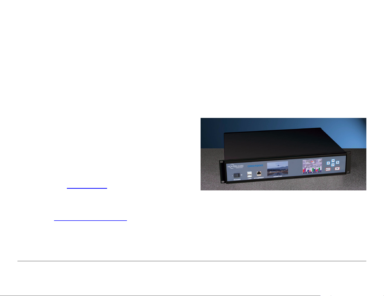
The DRS4000 Receiver (Figure 1-1) is ideal for Electronic News
Gathering (ENG), Digital Video Broadcast (DVB), mobile
communication, wireless airborne networks, and Outside
Broadcast (OB) systems, as well as for applications that require
hands off antenna diversity or deploy multiple units for up to a
four site cellular system
Figure 1-1: DRS4000 Receiver.
We’d appreciate any comments or suggestions you have about
this manual or the product. Your feedback helps us provide you
with better manuals.
If you’re viewing this manual electronically, it’s easy – just click
on the link below to send us an e-mail.
Feedback
Or, you can e-mail our Technical Support team at:
support@mrcbroadcast.com
Be sure to tell us what product you are writing about, and the title
of the manual.
Introduction 1-2DRS4000 Receiver User and Technical Manual
[photo of DRS4000 (similar to cover photo)]
The receiver consists of a 2RU rack-mountable, digital, microwave receiver that supports four antenna inputs. All functions
can be operated from the front control panel.
The DRS4000 Receiver uses the latest Maximal Ratio
Combining (MaxRC) technology to optimize the quality of the
transmitted signal. The DRS4000 supports Coded Orthogonal
Frequency Division Multiplexing (COFDM) demodulation, Link
Modulation System (LMS-T) demodulation, MPEG decoding in
Page 11

either standard definition or high definition (SD/HD), and optional
spectrum viewing, making it an excellent solution for expanding
and extending your remote capabilities.
with a corresponding increase in robustness over DVB-T. All
MRC and Link SD/HD ENG transmitters and wireless camera
systems also support LMS-T.
The DRS4000 Receiver exhibits more sensitivity, provides a
cleaner video image, and minimizes multipath effects when
compared to other microwave receivers.
The receiver operates on 100 to 260 VAC at 50 to 60 Hz. An
auto-sensing circuit detects actual line voltage.
You can readily change system parameters from the front panel
using a keypad and the control screen or by using a studiobased master controller. Frequently used settings can be saved
in one of 40 presets. A video monitor offers a display of live
video as well as an optional overlay of the RF spectrum.
In a typical DRS4000 system, each antenna is connected to a
low-noise block downconverter (BDC) by a short cable or direct
N-Type connector. The converters output a UHF signal through
coaxial cable to UHF input ports at the rear of the receiver. The
receiver and downconverters may be separated by up to 600
feet (183 m), depending on frequency and cable type.
Incoming signals and downconverter power travel on the same
cable using Bias-T interfaces in both the converter and the
DRS4000 Receiver. The DRS4000 Receiver samples the
signal-to-noise ratio (SNR) from all antennas, constructing an
optimized signal from one or more of the signals. High quality
75-ohm coaxial cable (RG6 or RG11) should be used to connect
the receiver to the downconverters.
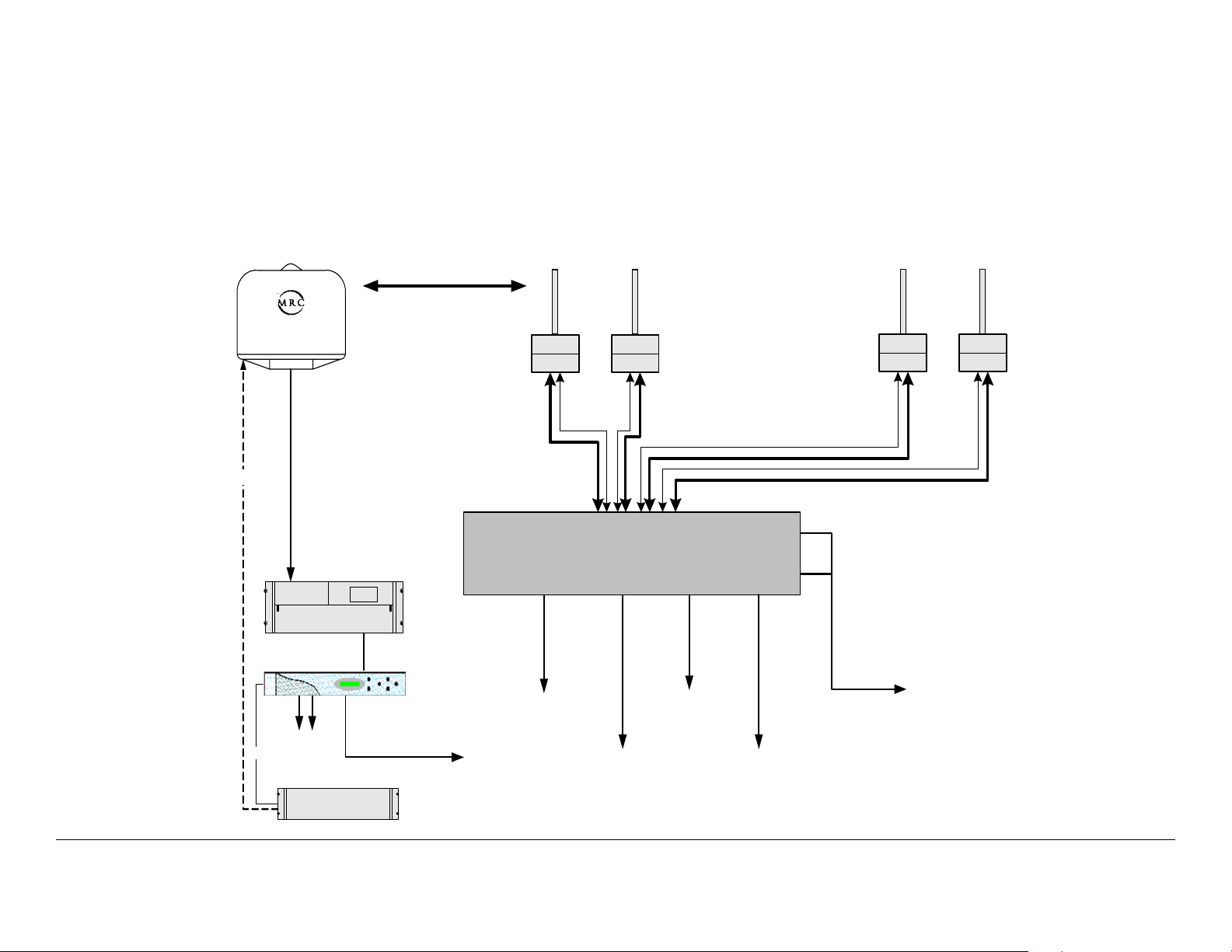
Figure 1-2 on page 1-4 depicts a typical configuration.
1.7 Features
The DRS4000 Receiver offers the following features:
• Two or four antenna inputs (DVB-T/LMS-T)
• Maximal ratio combining diversity technology
• ASI packet switching technology (Optional)
• Supports DVB-T and LMS-T demodulation technology
• Front panel live video monitor
• Real-time front panel monitoring for Signal-to-Noise
(SNR), Link Quality signal integrity (LQ), Receive Carrier
Level (RCL), and Bit Error Rate (BER)
• Embedded real-time operating system accessible via front
panel control screen
• Up to 40 programmable presets (saved settings) using the
DRS4000 front panel
• Rack Mountable, compact (EIA 19-inch rack, 2RU height)
• Supports 6, 7, and 8 MHz COFDM/DVB-T pedestals, and
10 and 20 MHz COFDM/LMS-T pedestals
The COFDM demodulator and SD/HD MPEG decoder support
standard Digital Video Broadcast-Terrestrial (DVB-T) 2K
operation as well as the highly advanced Link Modulation
System-Terrestrial (LMS-T). LMS-T employs COFDM
technology in a proprietary format that utilizes powerful LDPC
error correction codes to achieve a 30% increase in throughput
Introduction 1-3DRS4000 Receiver User and Technical Manual
• Internal web server for remote management via any
networked computer
• Controlling a remote camera
• Compatible with MRC and Link Research low-noise block
downconverters
Page 12
• Interfaces with MRC CodeRunner4 and MRX4000 Plus
products at the 70 MHz IF level
• Spectrum viewer option that overlays the video signal with
an RF spectrum (future option)
Figure 1-2: DRS4000 Receiver Typical 4-Input SD Configuration
Control
High Gain
Steerable
UltraScan II
MRC CodeRunner 4
CR4 Receiver
MRX4000
Independent
Receive Sites
BDC Support :
2, 3, 5, or 7 GHz
Filter
BDC
Band
Control
UHF Input/
+18.5V DC
Out
DRS4000
Filter
BDC
Sector RX
Antennas
Pole Mounted or
Angle Bracket
Mounted BDC
Package
BDC Support :
2, 3, 5, or 7 GHz
Filter
BDC
Band Control
+18.5V DC Out
Dual ASI Outputs
(To Backhaul or L2014)
Filter
BDC
UHF Input/
Com
SD Video/
Audio
Output
Slave Con tro ller
ASI Output
to Backhaul
Network/Control
& Monitoring
Output
Introduction 1-4DRS4000 Receiver User and Technical Manual
Low Delay
SDI Output
(option)
SDI
Outputs
(SD &HD)
SD Video/Audio
Output
Page 13

1.8 Hardware Components
1.9 Firmware Components
A typical installation consists of a receiver, antennas, low-noise
block downconverters, and cables.
1.8.1 Receiver
The DRS4000 Receiver accepts 2 or 4 antenna inputs and
incorporates MaxRC diversity technology, COFDM
demodulation, SD/HD MPEG decoding, and DVB-T and LMS-T
demodulation modes. With a front panel video monitor and
control screen, the receiver takes up only 2 RU of space in a 19inch rack. The receiver can be operated locally or remotely via a
master controller.
Base models include:
• DRS4000 4-input receiver with MaxRC, SD, and LMS-T
(DRS-R4LAJ)
• DRS4000 4-input receiver with MaxRC, SD, LMS-T, and
ASI Packet Switch (DRS-R4LAJP).
1.8.2 Antennas
MRC offers several types of antennas and several models within
some antenna types. See ”Antenna Options” on page 1-7 for
more information.
The DRS4000 Receiver is controlled by software installed on
programmable read-only memory (PROM). You can access this
firmware via the front control screen, and use it to monitor the
incoming signal and control settings such as channel and
frequency.
The firmware also provides a web browser interface that you can
access via a web browser on any PC or laptop computer as long
as both the DRS4000 Receiver and the computer are connected
to the same Local Area Network (LAN). You can also access the
web browser interface via a direct Ethernet connection. See
”Routine Operation” on page 2-1 for additional information.
1.10 Frequency Bands
The DRS4000 Receiver can operate in one of several factoryprogrammed frequency bands. You can select the band via the
front control screen or via a master controller interface at the
studio or command center.
MRC offers a range of block downconverters and antennas
designed for each frequency range. The downconverters
transform the incoming RF signal to a 110 to 860 MHz VHF/UHF
signal while the DRS4000 Receiver is capable of accepting a
signal in the range of 70 to 860 MHz.
1.8.3 Low Noise Block Downconverters
The DRS4000 Receiver is compatible with several MRC and
Link Research downconverters (LNBs). The downconverters
transform the incoming RF signal into UHF for input to the
receiver. See ”Block Downconverter Options” on page 1-6 for
additional information.
The following frequency bands are supported:
• 2 GHz
• 3 GHz (non-U.S.)
• 5 GHz
• 7 GHz
• 1.9 to 2.5 GHz / 6.4 to 7.1 GHz (dual band support option)
Introduction 1-5DRS4000 Receiver User and Technical Manual
Page 14

1.11 Standard/High Definition MPEG Decoding
The DRS4000 Receiver incorporates a Standard Definition (SD)
MPEG decoder. High Definition (HD) decoding is an option. The
SD decoder includes the following features:
• Central receive sites
• Outside Broadcasting (OB)
• Portable Broadcasting.
1.14 Compatibility
• 4:2:2 or 4:2:0 chroma support
• NTSC or PAL color television standard compliance with
four analog audio channels
• SDI outputs
• AES/EBU Digital Audio
• Wayside Data Channel
• DVB-ASI Output.
1.12 COFDM Demodulation
The DRS4000 Receiver incorporates a COFDM demodulator
that offers the following features:
• DVB-T Compliant
• DVB-T Bandwidth is Auto sensing (6 MHz, 7 MHz, or 8
MHz)
• LMS-T support
• LMS-T Bandwidth is 10 or 20 MHz selectable
The DRS4000 Receiver is compatible with the following
transmitters:
• MRC STRATA Portable Transmitter
• PTX PRO Transmitter
• MTX5000 Transmitter
• LINK XP
• LINK XP HD (future).
1.15 Options
You can customize the DRS4000 Receiver by choosing any of
the following options.
1.15.1 Block Downconverter Options
The following block downconverters are available as options:
MRC Models The following LNBs are supported:
• MRC 908149-5 LNB, 1.7 to 1.85 GHz
• QPSK, 16QAM, or 64QAM modulation
1.13 Applications
The DRS4000 Receiver has several applications:
• Electronic News Gathering (ENG)
• MRC 908149-2 LNB, 1.9 to 2.2 GHz
• MRC 908149-10 LNB, 1.9 to 2.2 GHz/2.2 to 2.49 GHz
Switchable
• MRC 908149-1 LNB, 1.99 to 2.5 GHz
• MRC 908149-4 LNB, 2.3 to 2.7 GHz
Introduction 1-6DRS4000 Receiver User and Technical Manual
Page 15

• MRC 908149-7 LNB, 3.2 to 3.6 GHz
• AES/EBU digital audio
• MRC 908149-8 LNB, 3.4 to 3.8 GHz
• MRC 908149-9 LNB, 3.5 to 3.95 GHz
• MRC 908149-3 LNB, 4.4 to 4.7 GHz
• MRC 908149-6 LNB, 4.8 to 5.0 GHz
• MRC 908149-11 LNB, 6.4 to 7.1 GHz
• MRC 908149-12 LNB, 6.425 to 7.7 GHz/6.7 to 7.1 GHz
Switchable
• MRC 908149-13 LNB, 6.425 to 6.7 GHz
• MRC 908149-14 LNB, 6.7 to 7.1 GHz.
Link Models The following LNBs and filters are supported:
• L3070 LNB base unit
• L3030 Input filter for L3070 1.95 to 2.7 GHz
• L3033 input filter for L3070 2.2 to 2.3 GHz
• L3034 input filter for L3070 2.3 to 2.4 GHz
• L3037 input filter for L3070 2.5 to 2.7 GHz
• L3060 input filter for L3070 3.4 to 3.6 GHz
• L3080 input filter for L3070 6.425 to 7.125 GHz.
• ASI output.
1.15.3 Antenna Options
To take advantage of diversity combining, you need to select
either 2 or 4 antennas. MRC works with you to select the proper
antennas for your receive site, including your legacy antennas
where feasible.
The following types of antennas are available:
• Omnidirectional These antennas are vertically polarized
and non-steerable. Models include the Omni-Directional
Antenna and OmniPole Antenna.
• Sector Scan These antennas include fixed-position
antennas such as sector panels. Models include
SectorScan.
• Steerable (pan only) These antennas offer full 360-
degree rotation in azimuth. Models include ProScan and
UltraScan DR.
• Steerable (pan and tilt) These antennas offer full
rotation in azimuth as well as tilt (elevation) control.
Models include MicroScan and Ellipse DR.
1.15.2 HD Decoding Upgrade
The DRS4000 base models includes an SD MPEG decoder.
The HD option includes the following features:
• 4:2:2 or 4:2:0 chroma support
• HD-SDI Output
• Four analog audio channels
1.15.4 RF Filter Options
The following RF filters are available as options for mounting
inside a 908441-1 box with a LNB:
• PCS/MMDS filter
• BAS relocation filter
1.15.5 Mounting Options
The DRS4000 Receiver is designed to mount in a standard EIA
Introduction 1-7DRS4000 Receiver User and Technical Manual
Page 16

19-inch rack, making it suitable for fixed mounting at a receive
site or for portable mounting in a vehicle. Only 2 rack units (RU)
of height are required.
1.15.6 Power Options
A voltage auto-sense feature detects input voltage, which can be
100 to 260 VAC at 50 to 60 Hz. A 3-prong power cable is
included.
The rear power connector includes a removable fuse holder with
a pair of 2-amp glass fuses.
1.15.7 Decryption Options
The receiver supports the Basic Interoperable Scrambling
System (BISS):
• BISS-1
• BISS-E.
1.15.8 Packet Switching Option
The packet switching option enables the addition of feature-rich
enhancements, including cellular diversity hubs and support for
existing central receivers through an ASI interface.
Introduction 1-8DRS4000 Receiver User and Technical Manual
Page 17

Routine Operation
2.1 Chapter Overview
This chapter provides basic information that will enable you to
operate your DRS4000 Receiver.
Here are the topics covered:
Topic Page
Controls, Indicators, and Connectors 2-2
Front Panel Controls, Indicators, and
Connectors
Rear Panel Connectors 2-4
PACKET Connectors 2-5
Preparing for Operation 2-5
Installation 2-5
Powering the Receiver 2-5
Control Menu Operations 2-9
Using the Video Monitor 2-8
Keypad Operation 2-8
Routine Operations 2-9
Control Menu Operations 2-9
Change Channel 2-10
Change Frequency 2-10
Monitor RF Band 2-11
Change Modulation Mode 2-11
Change Video Decoder 2-12
Select Audio Output 2-12
2-4
Select Polarity 2-13
Select a New Preset 2-13
Setup Menu Operations 2-13
Review Hardware Configurations 2-14
Select RF Switch Matrix 2-14
Select IP and MAC Addresses 2-15
Change Use Service Information Mode 2-16
Review or Change PIDs 2-16
Set Frame Sync 2-18
Set Frame Sync Offset 2-18
Set Video Color Bar Output 2-19
Adjust Analog Audio Level 2-19
Adjust Digital Audio Level 2-20
Adjust SDI Embedded Audio Level 2-20
Set RS-232 Data Output 2-21
Set Spectrum Overlay 2-21
Select Audio Output 2-22
Select Demodulator Switch 2-22
Enter Service Name 2-23
Set Video Fail Mode 2-23
Set NTSC Pedestal 2-24
Select Encryption Mode 2-24
Select/Edit Site Management Name 2-26
Activate Site Management 2-26
Select Packet Switch Configuration Unit
Mode
Select Packet Switch Configuration ASI Mode 2-27
Select Packet Switch Configuration Default
Service Name
2-27
2-28
Routine Operation 2-1DRS4000 Receiver User and Technical Manual
Page 18

Select Packet Switch Configuration ASI
Bitrate
Select BDC Type and Band Control 2-29
Complete RCL Calibration 2-30
Firmware Upgrade 2-30
EEPROM Initialization 2-31
Edit/Create Custom Frequency Band 2-31
Upgrade Tuner 2-32
Change Channel Spacing Password 2-32
Preset Menu Operations 2-32
Add a New Licensed Option 2-33
Camera Control Operations 2-34
Remote Operation 2-34
Common Features 2-34
Connect to the Web Browser 2-34
Perform Status Monitor 2-35
2-28
2.2 Controls, Indicators, and Connectors
Controls, indicators, and connectors contained on the front and
rear panels of the DRS4000 are shown in Figure 2-1 on page 2-
3.
Change RF, Demodulator, and Packet Switch
Configuration Settings
Change Decoder General Settings 2-36
Change Decoder Audio/Video Settings 2-37
Change Encryption Settings 2-37
Review Hardware/Software Configurations 2-38
Rename/Select Site Management 2-38
Change BDC/RF Switch Matrix 2-39
Change/Monitor Camera Settings 2-39
Select New Preset 2-39
2-36
Routine Operation 2-2DRS4000 Receiver User and Technical Manual
Page 19
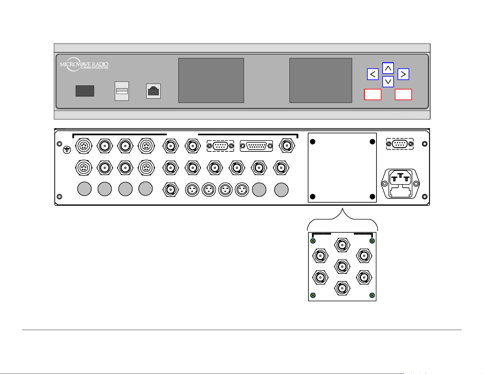
Figure 2-1: DRS4000 Front and Rear Panels
DRS4000
DRS4000
I
0
POWER USB ETHER NET MO NITO R
DIVERSITY
CTRL/MON1
CTRL/MON3
CTRL/MON5
BDC 1
BDC 3
BDC 2
BDC 4
BDC 6BDC 5
CTRL/MON2
CTRL/MON4
CTRL/MON6
70 MHz IN
CV 2CV 1
HD SDISD SDI HD MON
AUDIO 1
WAYSIDE DATA ALARM
AUDIO 2 AUDIO 3 AUDIO 4
Blank panel is standard.
Packet panel is optional.
ASI OUT ASI OUT
GEN LOCK
ASI IN
AES 2AES 1
ASI IN 2
(Blank Panel)
PACKET
ASI IN 1
ASI IN 3
BACK
OK
RS-232 CNTRL
AC IN 100-120/200-240V
50- 60Hz, 2A
POWER
ASI IN 4
ASI OUT
SDI OUT
ASI OUT
Routine Operation 2-3DRS4000 Receiver User and Technical Manual
Page 20

2.2.1 Front Panel Controls, Indicators, and Connectors
POWER Switch The POWER switch controls application of
power to the unit. When set to on ( I ), power is applied to the
unit. When set to off ( O ), power is removed from the unit.
USB Connector The USB 2.0 connector allows you to install
firmware updates from MRC via a flash drive.
ETHERNET Connector The RJ-45 ETHERNET connector
allows you to connect the receiver to a computer and use the
DRS4000 web browser interface to control the receiver.
MONITOR Screen The MONITOR screen provides a live view
of the incoming video signal. If the receiver loses the incoming
signal for any reason, the MONITOR screen will display either a
freeze frame or a blank screen.
With the spectrum viewer option installed, the monitor also
displays the RF spectrum as an overlay to the video display.
Control Menu The Control menu reports real-time data for the
video signal and shows current RF settings. The Control menu
also displays menus used to change system settings.
Keypad The keypad consists of easy-to-use push buttons that
provide access to all system parameters and settings. See
“Keypad Operation” on page 2-8 for details.
2.2.2 Rear Panel Connectors
The rear panel contains the connectors for power, diversity
inputs and outputs, and audio outputs. If the packet switching
subsystem is installed, the blank panel is replaced by the
PACKET connector panel.
The rear panel provides numerous inputs and outputs. These
inputs and outputs are as follows.
CNTL/MON 1 thru CTRL/MON 4 Connectors The control/
monitor connectors are 7-pin Lemo sockets that provide control
outputs and monitor inputs for the corresponding downconverter.
For example, CTRL/MON 4 controls and monitors BDC 4.
BDC 1 thru BDC 4 Connectors The block downconverter
(BDC) connectors are TNC connectors that accept the UHF
signals from the downconverters and their corresponding
antennas. To power each downconverter, +8.5/+18.5 VDC is
applied to the coaxial cable that runs from the BDC connector to
the downconverter.
CV 1 and CV 2 Connectors These Composite Video (CV)
connectors are 75 ohm, female, BNC connectors that provide
analog video signal outputs.
WAYSIDE DATA Connector This RS-232, 9-pin female
connector is the wayside channel, used for transfer of data such
as global positioning satellite (GPS) data or meta data from the
MPEG decoder. Using a standard RS-232 cable, you can
connect the receiver’s WAYSIDE DATA connector to a computer
or an auto-tracking antenna system.
ALARM Connector This DB-15 female connector connects to
single-pole single throw (SPST) switches for summary alarm
data for common faults and events and for site management
control. One SPST switch is for a minor alarm, one SPST switch
is for a major alarm, and four SPST switches are for site
management.
GEN LOCK Connector This 75 ohm, female, BNC connector
provides the Gen Lock input to the MPEG module.
The Frame Sync function must be turned on via the Set Frame
Sync Menu in order to use GEN LOCK.
SDI Connectors The SDI connectors are 75 ohm, female, BNC
connectors that provide SD/HD video data stream outputs from
the MPEG module that are compliant with SMPTE 259M.
Routine Operation 2-4DRS4000 Receiver User and Technical Manual
Page 21

ASI OUT Connectors The two ASI OUT connectors are 75
ohm, female, BNC connectors that provide ASI outputs for digital
video and audio distribution.
ohm, female, BNC connectors that provide a diversity ASI output
or a multiplexed ASI output according to the mode set for the
packet.
ASI IN Connector The ASI IN, 75 ohm, female, BNC connector
accepts an ASI signal input from another component. It is used
for local decoding of a SD/HD ASI stream when the receiver is
placed in external ASI mode.
70 MHz IN Connector This connector is a 75 ohm, female,
BNC connector that accepts input from another receiver. This is
an alternative input to BDC 1 and is selectable from the Control
screen menu.
AUDIO Connectors These mini-XLR connectors provide
analog audio 1 outputs and switch between analog audio 2 or
AES outputs.
RS-232 CNTRL Connector This connector is an RS-232, DB-9,
male connector that can be used to remotely control the
DRS4000 Receiver via a slave controller.
POWER connector The POWER connector accepts a standard
3-prong cable for AC power. An auto-sense circuit accepts
either 110 to 130 VAC or 205 to 260 VAC @ 2 amps. The 3prong male end must be modified for non-U.S. applications.
2.2.3 PACKET Connectors
The following connectors provide inputs and outputs for the
optional packet switching subsystem.
ASI IN 1 thru ASI IN 4 Connectors The 75 ohm, female, BNC
connectors allow up to four ASI inputs from different receive
sites, effectively acting as a diversity switch. They can also be
used as an ASI multiplexer. The maximum bit rate is adjustable
up to 40 Mbps.
ASI OUT Connectors The two ASI OUT connectors are 75
SDI OUT Connector This connector is a 75 ohm, female, BNC
connector that provides aa SD only digital video stream output.
2.3 Preparing for Operation
The procedures required to operate the DRS4000 receiver are
contained in the following paragraphs. The color LCD Control
menu and the keypad are used to control all features of the
receiver.
2.3.1 Installation
The DRS4000 receiver is typically mounted on a 19-inch (48.3
cm) rack. The unit and cabling are permanently installed and
power comes from facility power.
For additional information, refer to the “Installation” Chapter on
page 4-1.
The following paragraphs provide steps to power up and power
down the receiver. If the receiver is installed at an unattended
central receive site, then it typically stays powered up for
extended periods of time.
When the power switch is set to on ( I ), the video monitor will
initially display a blank screen and the Control menu will display
color bars, a logo screen, and finally the Control menu. The
settings displayed when the Control menu is displayed will be the
settings in effect when the unit was last powered down.
2.3.2 Powering the Receiver
The following paragraphs provide steps to power up and power
down the receiver. If the receiver is installed at an unattended
Routine Operation 2-5DRS4000 Receiver User and Technical Manual
Page 22
central receive site, then it typically stays powered up for
extended periods of time.
When the power switch is set to on ( I ), the video monitor will
initially display a blank screen and the Control menu will display
color bars, a logo screen, and finally the Control menu. The
settings displayed when the Control menu is displayed will be the
settings in effect when the unit was last powered down.
Power Up
To power up the receiver, perform the following steps.
1. Verify that the power cable is connected to the
POWER connector on the rear panel of the receiver
and is connected to an AC power source.
2. Verify that all coaxial cables and cable connectors are
properly connected to the front and rear panel
connectors, as required.
3. Verify that the AC power source is turned on.
- The Control menu goes through a power-up cycle
consisting of color bars, a product ID screen, and
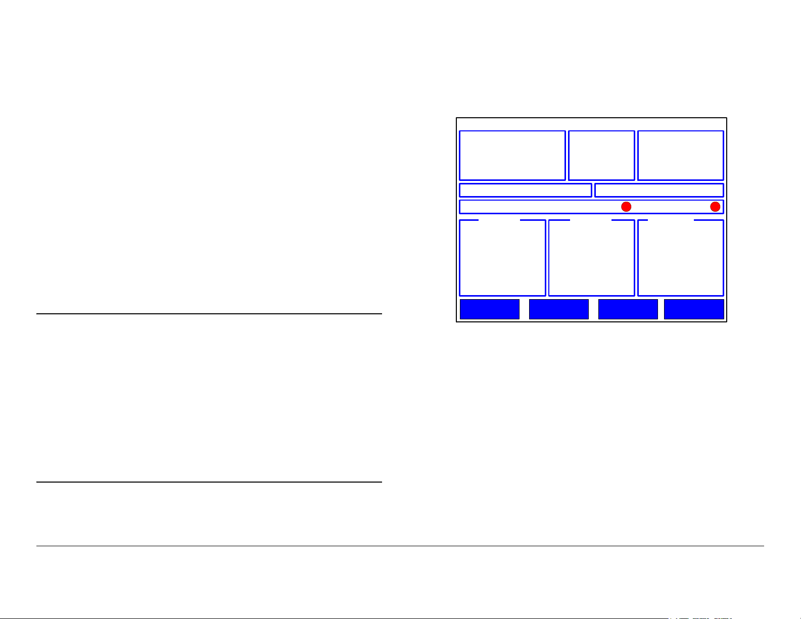
finally the initial Control menu, as shown in Figure 2-2.
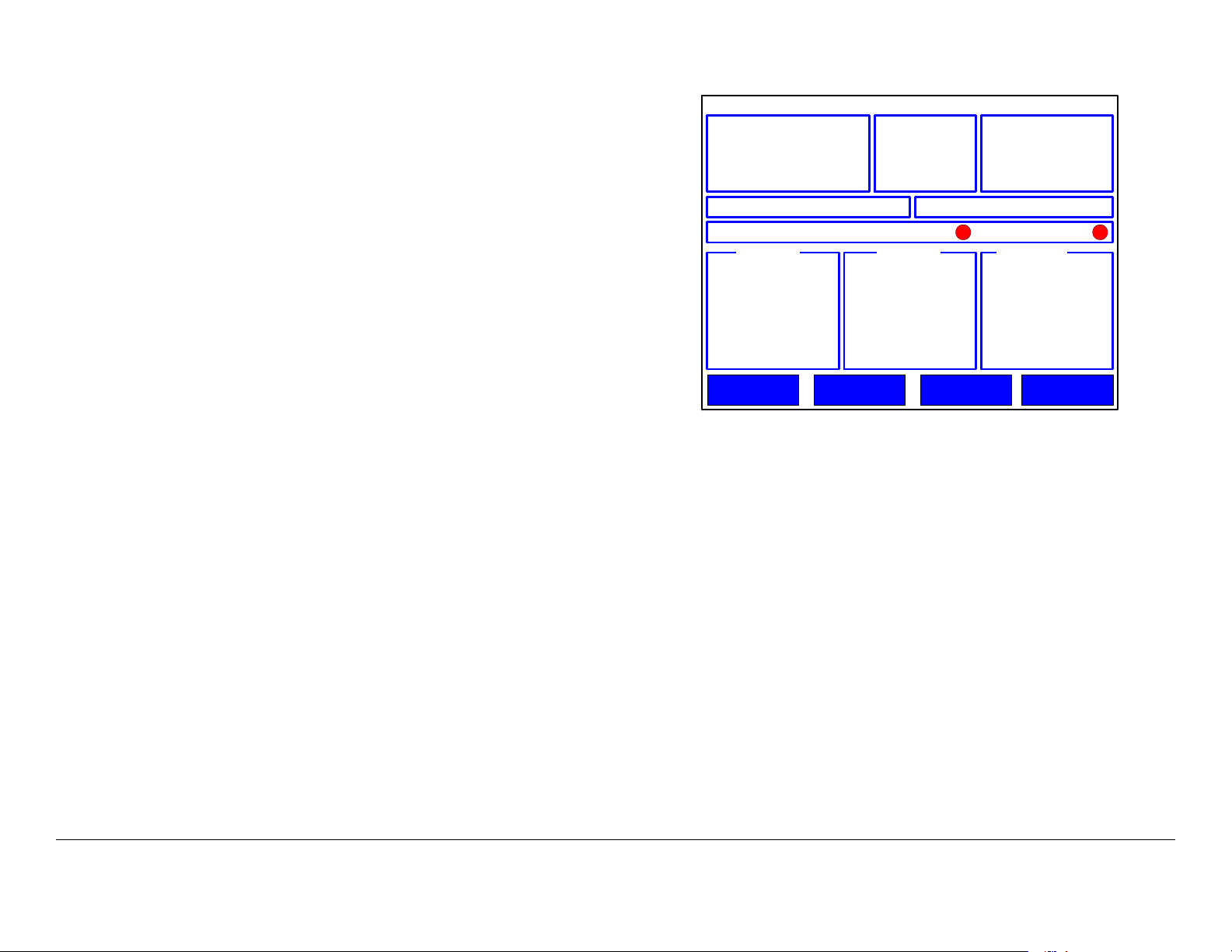
Figure 2-2: Initial Control Menu - Typical
DRS4000
Chan 1 (0) (17MHz)
Freq 1999.000 MHz
RFBand 1.9-2.5GHz
Mode DVB-T
Preset 1: XXXXXXXXXXXXX Service No Service
BER 2.16x10 COFDM Lock Vid Lock
RCL dBM SNR dB Link Qual
Setup Presets CameraOptions
-6
Mod
BW 8MHz
FEC
G/I 1/32
Video SD
Audio Analog
BitRt
Polarity Auto
Note
When power is set to on in the following step, the
settings displayed will be those in effect when the
receiver was powered down.
If there is no incoming signal, the RCL, SNR, and
Link Qual indicators will display their lowest values or
no values.
For a DRS4000 Receiver with four incoming signals,
the RCL, SNR, and Link Qual indicators will display
the A-B-C-D inputs.
4. Set the power switch on the front panel to on ( I ).
- The video monitor displays a blank screen.
Powering Down
To power down the receiver, perform the following steps.
1. Verify the Control menu is displayed.
2. Set the power switch on the front panel to off ( O ).
2.4 Control Menu Operations
The Control menu is displayed on the LCD color monitor and
provides access to the receiver and all its functions. This screen
is the graphical user interface (GUI) access to the settings and
functions of the receiver.
Routine Operation 2-6DRS4000 Receiver User and Technical Manual
Page 23
When you operate the receiver via the Control screen, you can
e
monitor Receive Carrier Level (RCL), Signal-to-Noise Ratio
(SNR), and Link Quality for all incoming video signals. You can
also change receiver settings such as channel and frequency
and save them as presets, as needed.
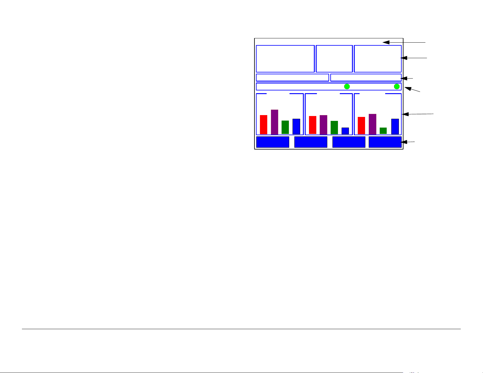
Figure 2-3: Control Screen - Typical
DRS4000
Chan 1 (0) (17MHz)
Freq 1999.000 MHz
RFBand 1.9-2.5GHz
Mode DVB-T
Mod QPSK
BW 8MHz
FEC 2/3
G/I 1/8
Video SD
Audio Analog
BitRt 15.61Mbps
Polarity Norm
Help text
Current
RF settings
The Control menu always displays the last saved settings.
For ease of use, the control screen is organized into the
following regions:
•Help Text
• Current RF Settings
• Preset Selected
• Service ID
• Data Status
• Signal Displays
• Menu Buttons.
These regions are identified in Figure 2-3 and explained in the
subsections that follow.
Preset 1: XXXXXXXXXXXXX Service No Service
BER 2.16x10 COFDM Lock Vid Lock
RCL dBM SNR dB Link Qual
-20
-44
B B B
A
Setup Presets CameraOptions
-6
B
21
20
-50
-57
CCC
A
D
13
5
D
7
6
A
2
5
D
Preset/Servic
Data Status
Signal
displays
Menu buttons
Help Text This region provides a brief description of each
setting and menu on the Control menu. For example, when
Chan is highlighted, the help text will display Change the
current channel settings.
Current RF Settings This region groups together the settings
for the incoming RF signal including, but not limited to, the
following:
• Channel
• Frequency
•RF Band
•Mode
• Modulation
• Bandwidth
• Forward Error Correction (FEC)
•Video
Routine Operation 2-7DRS4000 Receiver User and Technical Manual
Page 24
• Audio
• Bit Rate.
Preset Line This region displays the current Preset as a
number and a text label.
Service Line This line displays the read-only service ID of the
active transmitter.
The video monitor is typically blank when there is no incoming
video signal.
If, for any reason, the receiver should lose the incoming signal,
the monitor will display either a freeze frame or a blank screen.
This setting is controlled by the Video Fail Mode menu under
the Setup menu.
Data Status Line This region displays the following information:
• BER (Bit Error Rate)
• COFDM Lock - When green. indicates COFDM is locked;
when red, indicates COFDM is unlocked
• Vid Lock (video lock) - When green, indicates video is
locked; when red, indicates video is unlocked.
Signal Displays Area These areas displays real-time
indications of all antenna inputs as a set of animated vertical
bars.
•The RCL group of readings displays receive carrier levels
(RCL) in dBm.
•The SNR group displays signal-to-noise ratios (SNR) in
dBm.
•The Link Qual group displays link quality as a derived
number from 0 to 9 with 9 being the best signal.
Menu Buttons This region contains the menu selection buttons
that provide access to other menus and settings screens.
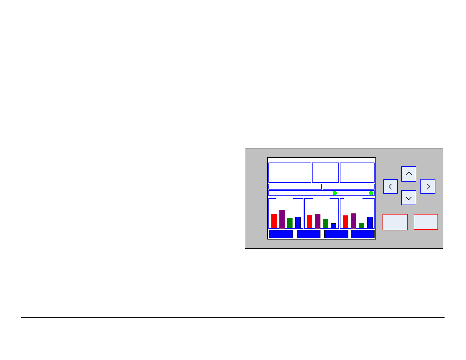
2.6 Keypad Operation
The control screen and keypad are shown in Figure 2-4. The
keypad consists of membrane-type switches that provide
momentary contact closure when pressed.
Figure 2-4: Control Menu and Keypad- Typical
DRS4000
Chan 1 (0) (17MHz)
Freq 1999.000 MHz
RFBand 1.9-2.5GHz
Mode DVB-T
Preset 1: XXXXXXXXXXXXX Service No Service
BER 2.16x10 COFDM Lock Vid Lock
RCL dBM SNR dB Link Qual
-20
-44
A
Setup Presets CameraOptions
-6
-50
-57
CCC
B B B
The keypad keys have the following functions:
Mod QPSK
BW 8MHz
FEC 2/3
G/I 1/8
B
21
20
13
A
D
Video SD
Audio Analog
BitRt 15.61Mbps
Polarity Norm
6
5
D
A
7
5
2
D
BACK
OK
2.5 Using the Video Monitor
The video monitor provides a live view of the incoming video
signal. With the spectrum viewer option, the monitor overlays
the video picture with an RF spectrum of the signal.
Routine Operation 2-8DRS4000 Receiver User and Technical Manual
Arrow Keys On the control screen, the arrow keys move the
highlighting cursor around the screen. Press the left or right
arrows to move across the screen, and press the up or down
arrows to move up or down the screen.
Page 25
On a settings screen, use the up or down arrow to move to
another setting, and use the left or right arrows to change a value
for a setting.
On a menu, use the up or down arrow to move to another menu
option.
Figure 2-5: Control Menu - Typical
DRS4000
Chan 1 (0) (17MHz)
Freq 1999.000 MHz
RFBand 1.9-2.5GHz
Mode DVB-T
Mod
BW 8MHz
FEC
G/I 1/32
Video SD
Audio Analog
BitRt
Polarity Auto
Back Key From a menu, the Back key displays the previous
menu. From a settings menu, Back cancels any changes you
just made and displays the starting Control menu or previous
menu. Back has no function on the Control menu.
OK Key From the Control menu, the OK key displays a settings
menu for the highlighted parameter or opens a submenu if a
menu button (Presets, Setup, Options, or Monitor) is
highlighted. From a settings menu, OK saves the current values.
2.7 Routine Operations
The Control menu offers convenient access to the most
frequently used settings. Prior to acquiring an incoming video
signal, you can quickly set any or all of the following settings
from the Control menu to match the settings of the remote
transmitter.
2.8 Control Menu Operations
For day-to-day operations, the Control menu (Figure 2-5) offers
convenient access to the most frequently used settings.
Preset 1: XXXXXXXXXXXXX Service No Service
BER 2.16x10 COFDM Lock Vid Lock
RCL dBM SNR dB Link Qual
Setup Presets CameraOptions
-6
Prior to acquiring an incoming video signal, you can quickly set
any or all of the following settings to match the settings of the
remote transmitter.
Routine Operation 2-9DRS4000 Receiver User and Technical Manual
Page 26
2.8.1 Change Channel
2.8.2 Change Frequency
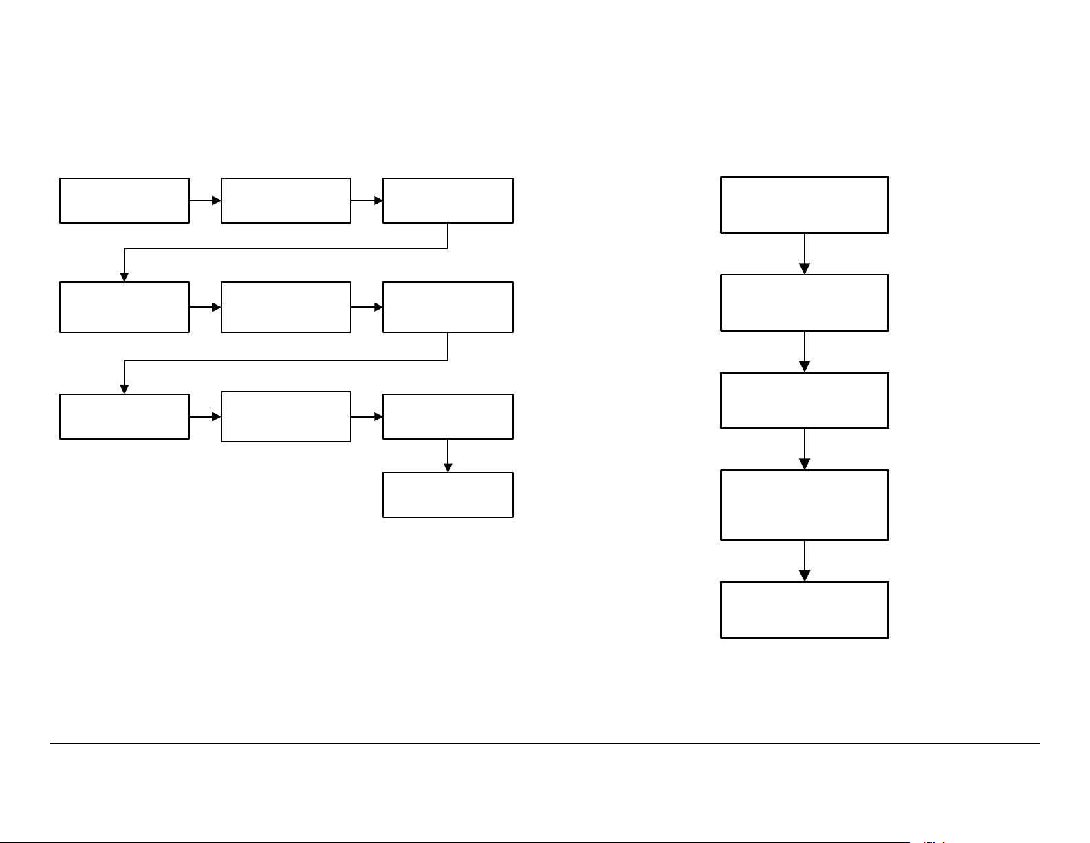
The steps required to change the channel, offset, and channel
spacing are provided in Figure 2-6.
Figure 2-6: Change Channel
Control menu is
displayed
Select Channel option
and select channel
required
When spacing is
changed, press OK
Select Chan and
press OK
Select Offset option
and select (-), (0), or
(+), as required
Enter Channel
Spacing Password
menu is displayed
Change Channel
menu is displayed
Select Spacing option
and select (XXMHz)
or (Cust), as required
Enter password
(default password is
0000) and press OK
Control menu is
displayed
The steps required to change the frequency are provided in
Figure 2-7.
Figure 2-7: Change Frequency
Control menu is
displayed
Select Freq and press
OK
Change Frequency
menu is displayed
Change frequency, as
required, and press
OK
Control menu is
displayed
Routine Operation 2-10DRS4000 Receiver User and Technical Manual
Page 27
2.8.3 Monitor RF Band
2.8.4 Change Modulation Mode
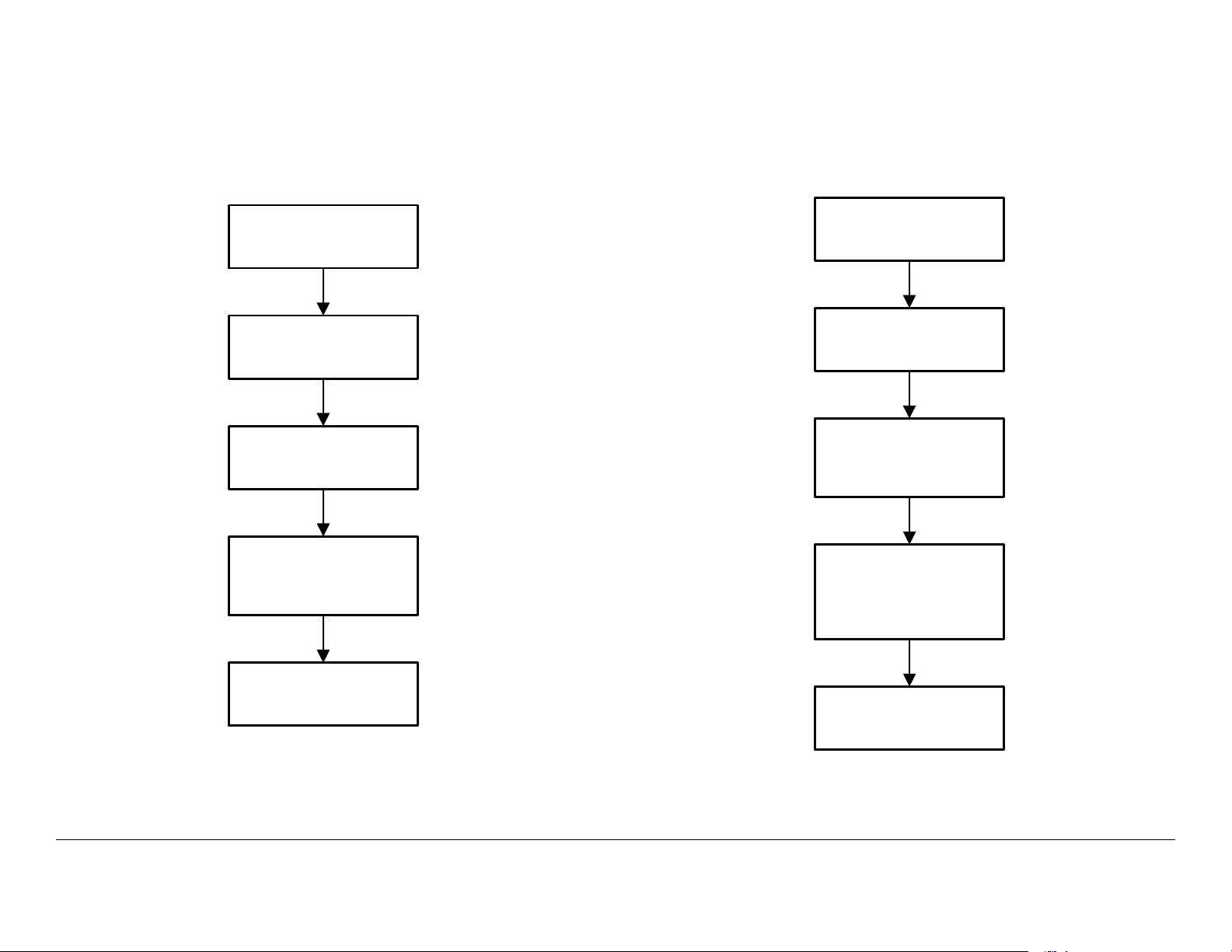
The steps required to monitor the RF band are provided in
Figure 2-8.
Figure 2-8: Change RF Band
Control menu is
displayed
Select RFBand and
press OK
Change RF Band
menu is displayed
Select RF band
required and press
OK
The steps required to change the modulation mode to DVB-T,
LMS-T (10MHz), or LMS-T (20MHz) are provided in Figure 2-9.
Figure 2-9: Change Modulation Mode
Control menu is
displayed
Select Mode and
press OK
Change Modulation
Mode menu is
displayed
Select DVB-T, LMS-T
(10MHz), or LMS-T
(20MHz), as required,
and press OK
Control menu is
displayed
Control menu is
displayed
Routine Operation 2-11DRS4000 Receiver User and Technical Manual
Page 28

2.8.5 Change Video Decoder
2.8.6 Select Audio Output
The decoder will automatically detect and decode NTSC or PAL
video during normal operation. The steps required to change the
video decoder to SD (PAL) or SD (NTSC) are provided in Figure
2-10.
Figure 2-10: Change Video Decoder
Control menu is
displayed
Select Video and
press OK
Change Decoder
Mode menu is
displayed
Select SD (PAL) or
SD (NTSC), as
required and press
OK
The steps required to select Channel 2 Analog or Digital audio
output is provided in Figure 2-11.
Figure 2-11: Select Audio Output
Control menu is
displayed
Select Audio and
press OK
Select Audio Output
menu is displayed
Select Channel 2,
select Analog or
Digital, as required,
and press OK
Control menu is
displayed
Control menu is
displayed
Routine Operation 2-12DRS4000 Receiver User and Technical Manual
Page 29

2.8.7 Select Polarity
2.8.8 Select a New Preset
The steps required to select Normal, Inverted, or Auto polarity
are provided in Figure 2-12.
Figure 2-12: Select OFDM Polarity
Control menu is
displayed
Select Polarity and
press OK
Change OFDM
Polarity menu is
displayed
Select Normal,
Inverted, or Auto, as
required, and press
OK
The steps required to select a new Preset are provided in Figure
2-13.
Figure 2-13: Select a New Preset
Control menu is
displayed
Select Preset and
press OK
Load Preset menu is
displayed
Select Preset required
and press OK
Control menu is
displayed and new
Preset is displayed
Control menu is
displayed
2.9 Setup Menu Operations
The procedures required to use the Setup menu options are
provided in the following paragraphs.
Routine Operation 2-13DRS4000 Receiver User and Technical Manual
Page 30

2.9.1 Review Hardware Configurations
2.9.2 Select RF Switch Matrix
The steps required to review the hardware and software/
firmware provided in your DRS4000 are contained in Figure 2-
14.
Figure 2-14: Review Hardware Configurations
Control menu is
displayed
Select Setup and
press OK
Setup Menu is
displayed
Select Hardware
Configuration and
press OK
The steps required to select the RF switch matrix for block
downconverters BDC 1 thru BDC 4 are provided in Figure 2-15.
Figure 2-15: Select RF Switch Matrix
Control menu is
displayed
Select RF Switch
Matrix and Input
Routing and press
OK
Select IF Source and
select BDC #1 or
External
Select Setup and
press OK
RF Switch Matrix
menu is displayed
NOTE
If the same input
option is selected for
more than one source,
an error screen will be
displayed and the
input will be rejected.
Setup Menu menu is
displayed
Select Decoder Input
and select ASI or
COFDM, as required
Select BDC #1 or
External and select
Input A thru Input D,
as required
Hardware
Configuration menu
is displayed
Review data, as
required, and press
Back until Control
menu is displayed
Select BDC #2 and
select the input
required
Control menu is
displayed
Select BDC #3 and
select the input
required
Select BDC #4, select
the input required, and
press OK
Routine Operation 2-14DRS4000 Receiver User and Technical Manual
Page 31

2.9.3 Select IP and MAC Addresses
The steps required to monitor or change IP and MAC addresses are provided in Figure 2-16.
Figure 2-16: Select IP and MAC Addresses
Select IP and MAC
Control menu is
displayed
Select Setup and
press OK
Setup Menu is
displayed
Address
Configuration option
and press OK
IP Stack Config
menu is displayed
Select Change IP
Address and press
OK
IP Address Config
menu is displayed
Select Modify IP
Address and press
OK
Modify IP address, as
required, and press
OK
Select Done and
press OK
AND/OR AND/OR
Select Change
Default Gateway and
press OK
Default Gateway
Config menu is
displayed
Select Modify Default
Gateway and press
OK
Modify gateway
address, as required,
and press OK
Select Done and
press OK
AND/OR
Select Change
Netmask and press
OK
Netmask Config
menu is displayed
Select Modify
Netmask and press
OK
Modify netmask
address, as required,
and press OK
Select Done and
press OK
Select Display IP
Settings and press
OK
View IP Settings
menu is displayed
Review IP settings, as
required
Press Back and
Control menu is
displayed
Press Back until
Control menu is
displayed
Press Back until
Control menu is
displayed
Press Back until
Control menu is
displayed
Routine Operation 2-15DRS4000 Receiver User and Technical Manual
Page 32

2.9.4 Change Use Service Information Mode
2.9.5 Review or Change PIDs
The steps required to enable or disable the service information
mode are provided in Figure 2-17.
Figure 2-17: Change Use Service Information
Control menu is
displayed
Setup Menu is
displayed
Configure Audio/
Video 1 menu is
displayed
Select Setup and
press OK
Select Audio/Video
Configuration and
press OK
Select Use SI Service
Information and
press OK
The steps required to review or change audio and/or video
program identifiers (PIDs) are provided in Figure 2-18 on page 2-
17. Please note that PIDs can only be changed if the Use SI
Service Information option is set to Off.
Use SI Service Info
menu is displayed
Press Back until
Control menu is
displayed
Select On or Off and
press OK
Routine Operation 2-16DRS4000 Receiver User and Technical Manual
Page 33

Figure 2-18: Review or Change PIDs
Control menu is
displayed
NOTE
It may be necessary
to select More... or
Back... to locate the
Set/View PIDS option.
Select Setup and
press OK
Select Set/View PIDS
and press OK
If Use SI Service
Information option is
set to On:
View PIDs (ReadOnly) menu is
displayed
Review PID data, as
required, and press
OK
Setup Menu is
displayed
OR
If Use SI Service
Information option is
set to Off:
Manual PIDs Edit
menu is displayed
Select PCR PID and
press OK
Select Audio/Video
Configuration and
press OK
Enter PID values, as
required, and press
OK
Select Audio 1 PID
and press OK
Enter PID values, as
required, and press
OK
Configure Audio/
Video X menu is
displayed
Select Data PID and
press OK
Enter PID values, as
required, and press
OK
Select Done and
press OK
Select Back until
Control menu is
displayed
Enter PID values, as
required, and press
OK
Select Video PID and
press OK
Routine Operation 2-17DRS4000 Receiver User and Technical Manual
Select Audio 2 PID
and press OK
Enter PID values, as
required, and press
OK
Select Back until
Control menu is
displayed
Page 34

2.9.6 Set Frame Sync
2.9.7 Set Frame Sync Offset
The steps required to set frame sync On or Off are provided in
Figure 2-19. When set to On, the decoder locks the video output
to an external reference at the GEN LOCK input on the rear
panel.
Figure 2-19: Set Frame Sync
Control menu is
displayed
Setup Menu is
displayed
Configure Audio/
Video X menu is
displayed
Select Setup and
press OK
Select Audio/Video
Configuration and
press OK
NOTE
It may be necessary
to select More... or
Back... to locate the
Set Frame Sync
option.
The steps required to set the frame sync offset are provided in
Figure 2-20.
Figure 2-20: Set Frame Sync Offset
Control menu is
displayed
Setup Menu is
displayed
Configure Audio/
Video X menu is
displayed
Select Setup and
press OK
Select Audio/Video
Configuration and
press OK
NOTE
It may be necessary
to select More... or
Back... to locate the
Set Frame Sync
Offset option.
Select Set Frame
Sync and press OK
Select On or Off and
press OK
Set Frame Sync
menu is displayed
Press Back until
Control menu is
displayed
Select Set Frame
Sync Offset and
press OK
Select offset value
required and press
OK
Edit Frame Sync
menu is displayed
Press Back until
Control menu is
displayed
Routine Operation 2-18DRS4000 Receiver User and Technical Manual
Page 35

2.9.8 Set Video Color Bar Output
2.9.9 Adjust Analog Audio Level
The steps required to set the video color bar output to On or Off
are provided in Figure 2-21.
Figure 2-21: Set Video Color Bar Output
Control menu is
displayed
Setup Menu is
displayed
Configure Audio/
Video X menu is
displayed
Select Setup and
press OK
Select Audio/Video
Configuration and
press OK
NOTE
It may be necessary
to select More... or
Back... to locate the
Set Video Output
option.
The steps required to adjust the analog audio level are provided
in Figure 2-22.
Figure 2-22: Adjust Analog Audio Level
Control menu is
displayed
Setup Menu is
displayed
Configure Audio/
Video X menu is
displayed
Select Adjust Analog
Audio Level and
press OK
Select Setup and
press OK
Select Audio/Video
Configuration and
press OK
NOTE
It may be necessary
to select More... or
Back... to locate the
Adjust Analog Audio
Level option.
Adjust Analog Audio
Level menu is
displayed
Select Set Video
Output and press OK
Select On or Off, as
required, and press
OK
Set Video Output
menu is displayed
Press Back until
Control menu is
displayed
Select Channel 1 and
enter attenuation level
required (Range is 0.0
to 6.0 dM)
Press Back until
Control menu is
displayed
Select Channel 2,
enter attenuation level
required (Range is 0.0
to 6.0 dM), and press
OK
Routine Operation 2-19DRS4000 Receiver User and Technical Manual
Page 36

2.9.10 Adjust Digital Audio Level
2.9.11 Adjust SDI Embedded Audio Level
The steps required to adjust the digital audio level are provided
in Figure 2-23.
Figure 2-23: Adjust Digital Audio Level
Control menu is
displayed
Setup Menu is
displayed
Configure Audio/
Video X menu is
displayed
Select Adjust Digital
Audio Level and
press OK
Select Setup and
press OK
Select Audio/Video
Configuration and
press OK
NOTE
It may be necessary
to select More... or
Back... to locate the
Adjust Digital Audio
Level option.
Adjust Digital Audio
Level menu is
displayed
The steps required to adjust the SDI embedded audio level are
provided in Figure 2-24.
Figure 2-24: Adjust SDI Embedded Audio Level
Control menu is
displayed
Setup Menu is
displayed
Configure Audio/
Video X menu is
displayed
Select Adjust SDI
Emb. Audio Level
and press OK
Select Setup and
press OK
Select Audio/Video
Configuration and
press OK
NOTE
It may be necessary
to select More... or
Back... to locate the
Adjust SDI Emb.
Audio Level option.
Adjust SDI Emb
Audio Level menu is
displayed
Select Channel 1 and
enter attenuation level
required (Range is 0.0
to 6.0 dM)
Press Back until
Control menu is
displayed
Select Channel 2,
enter attenuation level
required (Range is 0.0
to 6.0 dM), and press
OK
Select Channel 1 and
enter attenuation level
required (Range is 0.0
to 6.0 dM)
Press Back until
Control menu is
displayed
Select Channel 2,
enter attenuation level
required (Range is 0.0
to 6.0 dM), and press
OK
Routine Operation 2-20DRS4000 Receiver User and Technical Manual
Page 37

2.9.12 Set RS-232 Data Output
2.9.13 Set Spectrum Overlay
The steps required to set the RS-232 output On or Off are
provided in Figure 2-25.
Figure 2-25: Set RS-232 Data Output
Control menu is
displayed
Setup Menu is
displayed
Configure Audio/
Video X menu is
displayed
Select Setup and
press OK
Select Audio/Video
Configuration and
press OK
NOTE
It may be necessary
to select More... or
Back... to locate the
RS-232 Data Output
option.
The steps required to set the spectrum overlay feature to On or
Off is provided in Figure 2-26.
Figure 2-26: Set Spectrum Overlay
Control menu is
displayed
Setup Menu is
displayed
Configure Audio/
Video X menu is
displayed
Select Setup and
press OK
Select Audio/Video
Configuration and
press OK
NOTE
It may be necessary
to select More... or
Back... to locate the
Set Spectrum
Overlay option.
Select RS-232 Data
Output and press OK
Select On or Off and
press OK
RS-232 Data Output
menu is displayed
Press Back until
Control menu is
displayed
Select Set Spectrum
Overlay and press
OK
Select On or Off and
press OK
Set Spectrum
Overlay menu is
displayed
Press Back until
Control menu is
displayed
Routine Operation 2-21DRS4000 Receiver User and Technical Manual
Page 38

2.9.14 Select Audio Output
2.9.15 Select Demodulator Switch
The steps required to select Channel 2 digital or analog outputs
are provided in Figure 2-27.
Figure 2-27: Select Audio Output
Control menu is
displayed
Setup Menu is
displayed
Configure Audio/
Video X menu is
displayed
Select Setup and
press OK
Select Audio/Video
Configuration and
press OK
NOTE
It may be necessary
to select More... or
Back... to locate the
Select Audio Output
option.
The steps required to select demodulator ASI In or COFDM Out
are provided in Figure 2-28.
Figure 2-28: Select Demodulator Switch
Control menu is
displayed
Setup Menu is
displayed
Configure Audio/
Video X menu is
displayed
Select Setup and
press OK
Select Audio/Video
Configuration and
press OK
NOTE
It may be necessary
to select More... or
Back... to locate the
Select Demodulator
Switch option.
Select Select Audio
Output and press OK
Select Channel 2 and
select Analog or
Digital, as required
and press OK
Select Audio Output
menu is displayed
Press Back until
Control menu is
displayed
Select Select
Demodulator Switch
and press OK
Select ASI In or
COFDM Out, as
required and press
OK
Select Demodulator
Switch menu is
displayed
Press Back until
Control menu is
displayed
Routine Operation 2-22DRS4000 Receiver User and Technical Manual
Page 39

2.9.16 Enter Service Name
2.9.17 Set Video Fail Mode
The steps required to enter a new service name are provided in
Figure 2-29.
Figure 2-29: Enter Service Name
Control menu is
displayed
Setup Menu is
displayed
Configure Audio/
Video X menu is
displayed
Select Setup and
press OK
Select Audio/Video
Configuration and
press OK
NOTE
It may be necessary
to select More... or
Back... to locate the
Enter Service Name
option.
The steps required to set the video fail mode to a freeze frame or
a blue frame are provided in Figure 2-30.
Figure 2-30: Set Video Fail Mode
Control menu is
displayed
Setup Menu is
displayed
Configure Audio/
Video X menu is
displayed
Select Setup and
press OK
Select Audio/Video
Configuration and
press OK
NOTE
It may be necessary
to select More... or
Back... to locate the
Video Fail Mode
option.
Select Enter Service
Name and press OK
Enter service name
and press OK
Enter Service Name
menu is displayed
Press Back and
Control menu is
displayed
Select Video Fail
Mode and press OK
Select Freeze or Blue
and press OK
Video Fail Mode
menu is displayed
Press Back and
Control menu is
displayed
Routine Operation 2-23DRS4000 Receiver User and Technical Manual
Page 40

2.9.18 Set NTSC Pedestal
2.9.19 Select Encryption Mode
The steps required to set the NTSC pedestal to on or no
pedestal are provided in Figure 2-31.
Figure 2-31: Set NTSC Pedestal
Control menu is
displayed
Setup Menu is
displayed
Configure Audio/
Video 1 menu is
displayed
Select Setup and
press OK
Select Audio/Video
Configuration and
press OK
NOTE
It may be necessary
to select More... or
Back... to locate the
Set NTSC Pedestal
option.
The steps required to select the encryption mode are provided in
Figure 2-32 on page 2-25.
Select Set NTSC
Pedestal and press
OK
Select No Pedestal or
Pedestal and press
OK
Set NTSC Pedestal
menu is displayed
Press Back and
Control menu is
displayed
Routine Operation 2-24DRS4000 Receiver User and Technical Manual
Page 41

Figure 2-32: Set Encryption Mode
Control menu is
displayed
OR
Encryption Mode –
Off selected
Press Back until
Control menu is
displayed
Select Setup and
press OK
OR
Encryption Mode –
BISS-1 selected
Select Encryption
Support and press
OK
Encryption
Configuration menu
is displayed
Select Enter BISS-1
Key and press OK
Change BISS-1 Key
menu is displayed
Setup Menu is
displayed
OR
Encryption Mode –
BISS-E selected
Select Encryption
Support and press
OK
Encryption
Configuration menu
is displayed
Select Enter BISS-E
Key and press OK
Change BISS-E Key
menu is displayed
Select Encryption
Support and press
OK
Change BISS-E Inj.
Word menu is
displayed
Enter BISS-E ID key
data and press OK
Encryption
Configuration menu
is displayed
Press Back until
Control menu is
displayed
Encryption
Configuration menu
is displayed
Encryption Mode –
AES selected
Select Encryption
Support and press
OK
Encryption
Configuration menu
is displayed
Select Enter AES
Key and press OK
Change AES Key
menu is displayed
Select Encryption
Mode - Off, AES,
BISS-1, or BISS-E
and press OK
OR
Setup Menu is
displayed
Enter BISS-1 key data
and press OK
Encryption
Configuration menu
is displayed
Press Back until
Control menu is
displayed
Enter BISS-E key data
and press OK
Encryption
Configuration menu
is displayed
Select Enter BISS-E
Injected Id and press
OK
Enter AES key data
and press OK
Encryption
Configuration menu
is displayed
Press Back until
Control menu is
displayed
Routine Operation 2-25DRS4000 Receiver User and Technical Manual
Page 42

2.9.20 Select/Edit Site Management Name
2.9.21 Activate Site Management
The steps required to edit or select a site management name are
provided in Figure 2-33.
Figure 2-33: Select/Edit Site Management Name
Control menu is
displayed
Select Site
Management Control
and press OK
Site Mgmt
Configuration menu
is displayed
Enter new site name
and press OK
Select Setup and
press OK
Site Management
Menu is displayed
Select site name to be
changed and press
OK
Site Mgmt
Configuration menu
is displayed
Setup Menu is
displayed
Select Edit Site
Management and
press OK
Edit Site Mgmt
Name: menu is
displayed
Press Back until
Control menu is
displayed
The steps required to set site management to On or Off are
provided in Figure 2-34.
Figure 2-34: Activate Site Management
Control menu is
displayed
Setup Menu is
displayed
Site Management
Menu is displayed
Select Setup and
press OK
Select Site
Management Control
and press OK
Select Activate Site
Management and
press OK
Site Mgmt
Configuration menu
is displayed
Change each site to
On or Off, as
required, and press
OK
Control menu is
displayed
Routine Operation 2-26DRS4000 Receiver User and Technical Manual
Page 43

2.9.22 Select Packet Switch Configuration Unit Mode
2.9.23 Select Packet Switch Configuration ASI Mode
The steps required to select the packet switch unit mode
Diversity or Remux mode are provided in Figure 2-35.
Figure 2-35: Select Packet Switch Configuration Unit Mode
Control menu is
displayed
Setup Menu is
displayed
Packet Switch
Config. menu is
displayed
Select Setup and
press OK
Select Packet Switch
Configuration and
press OK
Select Unit Mode and
press OK
The procedure required to select the packet switch 188 Byte or
204 Byte ASI mode are provided in Figure 2-36.
Figure 2-36: Select Packet Switch Configuration ASI Mode
Control menu is
displayed
Setup Menu is
displayed
Packet Switch
Config. menu is
displayed
Select Setup and
press OK
Select Packet Switch
Configuration and
press OK
Select ASI Mode and
press OK
Packet Switch Unit
Mode menu is
displayed
Press Back until
Control menu is
displayed
Select Diversity or
Remux, as required,
and press OK
ASI Mode menu is
displayed
Press Back until
Control menu is
displayed
Select 188 Byte or
204 Byte, as required,
and press OK
Routine Operation 2-27DRS4000 Receiver User and Technical Manual
Page 44

2.9.24 Select Packet Switch Configuration Default Service Name
2.9.25 Select Packet Switch Configuration ASI Bitrate
The steps required to select the packet switch configuration
default service name are provided in Figure 2-37.
Figure 2-37: Select Packet Switch Configuration Default
Service Name
Control menu is
displayed
Setup Menu is
displayed
Packet Switch
Config. menu is
displayed
Select Setup and
press OK
Select Packet Switch
Configuration and
press OK
Select Default
Service Name and
press OK
The steps required to select the packet switch configuration ASI
bitrate are provided in Figure 2-38.
Figure 2-38: Select Packet Switch Configuration ASI Bitrate
Control menu is
displayed
Setup Menu is
displayed
Packet Switch
Config. menu is
displayed
Select Setup and
press OK
Select Packet Switch
Configuration and
press OK
Select ASI Bitrate
and press OK
Default Service
Name menu is
displayed
Press Back until
Control menu is
displayed
Enter default service
name, as required,
and press OK
Update ASI Bitrate
menu is displayed
Press Back until
Control menu is
displayed
Enter bitrate required
and press OK
Routine Operation 2-28DRS4000 Receiver User and Technical Manual
Page 45

2.9.26 Select BDC Type and Band Control
The steps required to select the BDC type and band control are provided in Figure 2-39.
Figure 2-39: Select BDC Type and Band Control
Control menu is
displayed
Advanced Setup
Menu is displayed
OR
Link option selected
Select Link BDC
menu is displayed
Select Link option
required and press
OK
Advanced Setup
Menu is displayed
Select Setup and
press OK
Select BDC Type and
Band Control and
press OK
OR OR
MRC LNB option
selected
Select MRC LNB
menu is displayed
Select MRC option
required and press
OK
Advanced Setup
Menu is displayed
Setup Menu is
displayed
BDC Type menu is
displayed
TANDBERG BDC
option selected
Select TANDBERG
BDC menu is
displayed
Select Link option
required and press
OK
Advanced Setup
Menu is displayed
Select Advanced
Setup and press OK
Select Link, MRC
LNB, or TANDBERG
BDC and press OK
Select BDC Power
and press OK
Confirm Proper BDC
Selected menu is
displayed
CAUTION
To avoid damage,
verify the BDC type
and band connected
to the receiver match
the BDC type and
band selected
previously.
Press OK and BDC
Power Settings menu
is displayed
Select Global – All
Off, All On, or
Individual and press
OK
OR
Global – All Off or All
On selected
Advanced Setup
Menu is displayed
Press Back until
Control menu is
displayed
Global – Individual
selected
For each individual
BDC, select On or
Off. When all BDCs
have been set to On
or Off, press OK
Routine Operation 2-29DRS4000 Receiver User and Technical Manual
OR
Advanced Setup
Menu is displayed
Press Back and
Control menu is
displayed
Page 46

2.9.27 Complete RCL Calibration
2.9.28 Firmware Upgrade
The steps required to complete RCL calibration are provided in
Figure 2-40. The IF cable loss must be determined for each
input before proceeding. Look up your cable specifications and
calculate the loss at approximately 500 MHz. As an example, for
Belden 7731A cable, the loss per 100 ft. at 540 MHz is 3.06 dB.
If you have 200 feet of cable, the loss is approximately 6 dB.
Figure 2-40: Complete RCL Calibration
Control menu is
displayed
Select Advanced
Setup and press OK
BDC Calibration menu
is displayed
Select IF Loss and
enter calculated value
(range is 0 to 40.1 dB)
Select Setup and press
OK
Advanced Setup Menu
is displayed
Select the BDC to
calibrated and press
OK
Advanced Setup Menu
is displayed
Setup Menu is
displayed
Select RCL Calibration
and press OK
BDC #X menu is
displayed
Press Back until
Control menu is
displayed
The steps required to upgrade the firmware contained in your
DRS4000 are provided in Figure 2-41. Firmware upgrades are
available from MRC via your E-Synergy portal.
Figure 2-41: Upgrade Firmware
Control menu is
displayed
Select Advanced
Setup and press OK
Firmware Upgrade
menu is displayed
Firmware Upgrade
menu is displayed
indicating update
progress
Select Setup and press
OK
Advanced Setup Menu
is displayed
Insert USB flash drive
containing new
firmware in USB
connector
After a short delay,
observe Verify
Complete. Please
remove flash drive and
power cycle message is
displayed
Setup Menu is
displayed
Select Upgrade
Firmware and press
OK
Select firmware to be
upgraded and press OK
Remove USB flash
drive from USB
connector
Set POWER switch to
off ( O ) and then to on (
I )
When power up cycle
is complete, Control
menu is displayed
Routine Operation 2-30DRS4000 Receiver User and Technical Manual
Page 47

2.9.29 EEPROM Initialization
2.9.30 Edit/Create Custom Frequency Band
The steps required to initialize the receiver EEPROM are
provided in Figure 2-42. All Presets will be erased from memory
when performing this procedure. Initializing the EEPROM
affects the stored Presets and RCL calibrations. After
performing this procedure, “Complete RCL Calibration” on
page 2-30.
Figure 2-42: EEPROM Initialization
Control menu is
displayed
Select Advanced
Setup and press OK
EEPROM Initialization
menu is displayed
Select Setup and press
OK
Advanced Setup Menu
is displayed
CAUTION
When OK is selected,
all existing Presets will
be lost. Press OK to
continue. Press Back
to cancel.
Setup Menu is
displayed
Select EEPROM
Initialization and press
OK
Press OK and progress
screen is displayed
The steps required to edit or create a custom frequency band is
provided in Figure 2-43.
Figure 2-43: Edit/Create Custom Frequency Band
Control menu is
displayed
Select Advanced
Setup and press OK
Enter Custom
Channel Password
menu is displayed
NOTE
Multiple plans are listed
in the Edit Custom
Band Plan menu. Use
Up/Down to select the
band plan applicable to
your system.
Select Setup and press
OK
Advanced Setup Menu
is displayed
Enter password and
press OK
Select band plan
required and press OK
Setup Menu is
displayed
Select Edit Custom
Plan and press OK
Edit Custom Band
Plan menu is displayed
Edit XX-XXGHz
Custom menu is
displayed
After a short delay,
observe EEPROM
Successfully
Initialized. Press OK
to continue. message
is displayed
Press Back until the
Control menu is
displayed
Press OK and Loading
initial configuration
message is displayed
After a short delay,
the Advanced Setup
Menu is displayed
Routine Operation 2-31DRS4000 Receiver User and Technical Manual
Select channel and
offset to be modified
and press OK
Press Back until
Control menu is
displayed
Edit Custom
Frequency Menu is
displayed
Enter custom frequency
required and press OK
Page 48

2.9.31 Upgrade Tuner
2.9.32 Change Channel Spacing Password
The steps required to upgrade your tuner are provided in Figure
2-45. This procedure requires password access and must only
be performed by your systems administrator.
Figure 2-44: Upgrade Tuner
Control menu is
displayed
Select Advanced
Setup and press OK
Enter Upgrade Code
menu is displayed
Select Enter License
Code and press OK
Select Setup and
press OK
Advanced Setup
Menu is displayed
Enter the tuner
upgrade code and
press OK
Enter License Code
menu is displayed
Setup Menu is
displayed
Select Upgrade
Tuner and press OK
Options Menu is
displayed
Enter license code
and press OK
The steps required to change the channel spacing password are
contained in Figure 2-45. This procedure should be performed
by the system administrator.
Figure 2-45: Change Channel Spacing Password
Control menu is
displayed
Select Advanced
Setup and press OK
Enter Password menu
is displayed
Enter new password
and press OK
Select Setup and press
OK
Advanced Setup Menu
is displayed
Enter password (default
password is DRS4K)
and press OK
Observe New
Password screen is
displayed reflecting the
new password and
press OK
Setup Menu is
displayed
Select Administrator
Settings and press OK
Enter Channel
Spacing Password
menu is displayed
Observe New
Password screen is
displayed and press
OK
Press Back until
Control menu is
displayed
Press Back until
Control menu is
displayed
2.10 Preset Menu Operations
The steps required to load, save, or delete a Preset are provided
in Figure 2-46 on page 2-33. In order to load a Preset, the
Routine Operation 2-32DRS4000 Receiver User and Technical Manual
Page 49

Preset must be contained in the Load Preset menu. To save a
Preset, the current Preset settings must be saved and added to
the Preset menus. When deleting a Preset, only the selected
Preset will be deleted from the Preset menus.
Figure 2-46: Load, Save, or Delete a Preset
Control menu is
displayed
Select Presets and
press OK
Preset Menu is
displayed
OR OR
Select Load Preset and
press OK
Load Preset menu is
displayed
Select Preset required
and press OK
Select Save Preset and
press OK
Save Preset menu is
displayed
Enter Preset name
required and press OK
Select Delete Preset
and press OK
Delete Preset menu is
displayed
Select Preset to be
deleted and press OK
2.11 Add a New Licensed Option
The steps required to add licensed options to your DRS4000 are
contained in Figure 2-47. Only licensed options applicable to the
hardware options contained in your receiver can be installed.
The DRS4000 does not have to be returned to the factory to add
licensed options applicable to your receiver configuration. The
internal software contains a license manager feature that allows
you to add licensed features to your DRS4000 that were not
initially ordered with your DRS4000.
In order to add a licensed option to your receiver, you must
obtain a license key applicable to the option required. This
license key is available only from MRC. Your receiver must
also contain the hardware applicable to the licensed option.
When ordering a license key from MRC, you must provide MRC
with the serial number of your DRS4000.
The procedure required to install a new licensed option, after
obtaining the license key from MRC, is provided in Figure 2-47.
This procedure is generic and can be used to install all licensed
options in your DRS4000. Each licensed option contained in
your receiver requires an individual license key.
Figure 2-47: Add a Licensed Option
Control menu is
displayed
Preset Saved menu is
displayed
Control menu is
displayed
Delete Preset?? menu
displayed
Control menu is
displayed
Routine Operation 2-33DRS4000 Receiver User and Technical Manual
Control menu is
displayed
Enter license code and
press OK
Select Options and
press OK
Confirm license code
change menu is
displayed
Observe Options
Menu is displayed and
press OK
Press Back until
Control menu is
displayed
Page 50

2.12 Camera Control Operations
This capability is not currently functional.
- Channel Bandwidth (12 MHz, 17 MHz, or Custom)
- Frequency
-RF Band.
2.13 Remote Operation
When the receiver is connected to your local area network, you
can control and maintain it from any computer on the network via
the built-in DRS4000 web server software.
The web server is designed to serve up web pages via a
networked PC web browser. The web browser interface
provides limited access to menus and screens you can access
from the receiver’s control panel.
From the remote location, Preset settings can be selected or
changed, but cannot be saved or deleted. Presets can only be
saved or deleted locally via the DRS4000 front panel.
2.13.1 Common Features
Each web page provides tabs used to select the various options
available on the individual pages. The individual pages may
contain pull-down menus, text boxes, and option selection
buttons.
Monitor Panels Tab The Monitor Panels tab returns you to the
Monitor Panels page from anywhere in the web interface. The
Monitor Panels page contains the same information as is
contained on the receiver Control menu.
Tuner/Demodulator Configuration Tab The Tuner/
Demodulator Configuration tab allows you to select and/or
change the following:
• RF Settings:
- Channel 1 - 10
- Channel Offset (-, 0, or +)
• Demodulator Settings:
- Mode (DVB-T, LMS-T (10 MHz, or LMS-T (20 MHz))
- Polarity (Normal, Inverted, or Auto).
• Packet Switch Settings:
- Unit Mode (Diversity or Remux)
- ASI Mode (188 Byte or 204 Byte)
- Default Service Name
- ASI Bitrate.
Decoder Configuration Tab The Decoder Configuration tab
provides access to the Decoder General Settings, Audio/
Video Settings, and the Encryption Settings tabs and their
associated settings and options.
System Configuration Tab The System Configuration tab
provides access to the Hardware Info, Site Management,
Matrix/BDC Setup, and Camera Settings tabs.
Presets Tab The Presets tab provides the tab required to
change the current Preset or to review current Preset settings.
2.13.2 Connect to the Web Browser
To access the receiver from a networked PC, perform the
following steps:
1. Verify the DRS4000 is powered up and is connected to
the network.
2. Verify an Ethernet cable is connected between the
receiver front panel ETHERNET connector and a
nearby LAN connection.
Routine Operation 2-34DRS4000 Receiver User and Technical Manual
Page 51

3. Obtain the IP address for the receiver. See ”Review
Hardware Configurations” on page 2-14.
4. At the remote PC, open your web browser, enter the
receiver IP address into the browser address field, and
press the Enter key.
5. Observe the DRS4000 web browser page opens. See
Figure 2-48.
Figure 2-48: Monitor Page - Typical
1. Verify the DRS4000 is connected to the PC web
browser per “Connect to the Web Browser” on page 2-
34.
Note
2. Select the Monitor Panels tab and verify the Monitor
Figure 2-49: Monitor Panels Tab - Typical
When the receiver is on line and is actively receiving,
the Antenna Metrics section of the page will display
the same values displayed on the DRS4000 Control
menu.
Panels page is displayed. See Figure 2-49.
2.13.3 Perform Status Monitor
The procedure required to perform status monitor is provided in
the following steps. All steps are performed at the remote PC.
Routine Operation 2-35DRS4000 Receiver User and Technical Manual
Page 52

2.13.4 Change RF, Demodulator, and Packet Switch Configuration Settings
The procedure required to change RF settings, including
channel, frequency, and RF band; demodulator settings,
including mode and polarity; and packet switch settings,
including unit mode, ASI mode, default service name, and ASI
bitrate, is contained in the following steps.
1. Verify the DRS4000 is connected to the remote PC
per “Connect to the Web Browser” on page 2-34.
2. Select the Tuner/Demodulator Configuration tab.
See Figure 2-50.
3. Select pull-down menu(s) or text box(es) to be
changed, make required change(s), and select the
corresponding Change option button.
2.13.5 Change Decoder General Settings
The procedure required to change general decoder settings is
contained in the following steps.
1. Verify the DRS4000 is connected to the remote PC
per “Connect to the Web Browser” on page 2-34.
2. Select the Decoder Configuration tab. See Figure 2-
51.
Figure 2-50: Tuner/Demodulator Configuration Tab - Typical
Figure 2-51: Decoder Configuration Tab - Typical
Routine Operation 2-36DRS4000 Receiver User and Technical Manual
Page 53

3. Select pull-down menu(s) or text box(es) to be
changed, make required change, and select the
corresponding Change option button(s), as required.
4. Select pull-down menu(s) or text box(es) to be
changed, make required change, and select the
corresponding Change option button, as required.
2.13.6 Change Decoder Audio/Video Settings
The procedure required to change decoder audio and video
settings is contained in the following steps.
1. Verify the DRS4000 is connected to the remote PC
per “Connect to the Web Browser” on page 2-34.
2. Select the Decoder Configuration tab.
3. Select the Audio/Video Settings tab. See Figure 2-
52.
Figure 2-52: Audio/Video Settings Tab - Typical
2.13.7 Change Encryption Settings
The procedure required to change encryption settings is
contained in the following steps.
1. Verify the DRS4000 is connected to the remote PC
per “Connect to the Web Browser” on page 2-34.
2. Select the Decoder Configuration tab.
3. Select the Encryption Settings tab. See Figure 2-53.
Figure 2-53: Encryption Settings Tab - Typical
Routine Operation 2-37DRS4000 Receiver User and Technical Manual
Page 54

4. Select encryption mode required, enter the encryption
key(s), as required, and select the corresponding
Change option button(s).
4. Review data, as required.
2.13.9 Rename/Select Site Management
2.13.8 Review Hardware/Software Configurations
The procedure required to review diversity receiver, MPEG
decoder, processor board, and packet switch serial numbers and
software revisions is contained in the following steps.
1. Verify the DRS4000 is connected to the remote PC
per “Connect to the Web Browser” on page 2-34.
2. Select the System Configuration tab.
3. Select the Hardware Info tab. See Figure 2-54.
Figure 2-54: System Configuration Hardware Info Tab Typi cal
The procedure required to set site management On or Off is
contained in the following steps.
1. Verify the DRS4000 is connected to the remote PC
per “Connect to the Web Browser” on page 2-34.
2. Select the System Configuration tab.
3. Select the Site Management tab. See Figure 2-55.
Figure 2-55: System Configuration Hardware Info Tab Typica l
Routine Operation 2-38DRS4000 Receiver User and Technical Manual
Page 55

4. Use the Site Management pull-down menus to select
On or Off option for each site, as required, and select
the Change option button.
2.13.10 Change BDC/RF Switch Matrix
The procedure required to select block downconverter (BDC)
types, to select BDC power, and to change the RF switch matrix
is contained in the following steps.
1. Verify the DRS4000 is connected to the remote PC
per “Connect to the Web Browser” on page 2-34.
CAUTION
Do not change BDC types UNLESS the BDC
type has actually been changed.
If BDC type selected is not contained in the
system, equipment damage will occur!
4. Use the BDC Configuration pull-down menus to
select the type and power settings, as required, and
select the corresponding Change option button(s).
2. Select the System Configuration tab.
3. Select the Matrix/BDC Setup tab. See Figure 2-56.
Figure 2-56: System Configuration Tab - Typical
Note
5. Use the RF Switch Matrix pull-down menus to select
If the same input option is selected for more than one
source, the settings will be rejected when the Change
option button is selected.
the inputs required and select the Change option
button.
2.13.11 Change/Monitor Camera Settings
The System Configuration - Camera Settings tab options are
not currently active.
2.13.12 Select New Preset
The procedure required to select a new Preset is contained in
the following steps. When a new Preset is selected during
performance of this procedure, the selected Preset settings will
be displayed in the Preset Details section of the Presets page
as soon as the Change option button is selected.
1. Verify the DRS4000 is connected to the remote PC
per “Connect to the Web Browser” on page 2-34.
Routine Operation 2-39DRS4000 Receiver User and Technical Manual
Page 56

2. Select the Presets tab. See Figure 2-57.
Figure 2-57: System Configuration Tab - Typical
3. Select the Current Preset: pull-down menu, select the
Preset required, and select the Change option button.
Routine Operation 2-40DRS4000 Receiver User and Technical Manual
Page 57

3
Troubleshooting
3.1 Chapter Overview
This chapter provides troubleshooting procedures for technical
problems that an operator may encounter. The problems are
organized into the following categories: video, audio, and
general system.
For each component, a problem-cause-action table states one or
more possible causes. For each possible cause, the table
provides one or more suggested actions that you can use.
Perform the suggested actions until you either fix the problem or
determine that you need technical support from MRC.
The following troubleshooting topics are discussed. Whenever
the suggested action requires more than a few steps, a link takes
you to a separate procedure.
Topic Page
Video Problems 3-2
Audio Problems 3-4
General System Problems 3-5
Troubleshooting 3-1DRS4000 Receiver User and Technical Manual
Page 58

3.2 Video Problems
The following table describes video problems.
Table 3-1: Video Problems
Problem Possible Cause Suggested Actions
No video
• Loose or disconnected UHF cables at
receiver.
• Loose cable at camera or transmitter.
• Receiver set to the wrong RF band,
channel, or other setting.
• Wrong preset is selected.
• All the antennas or BDCs are
disconnected or damaged.
• Power cable for receiver is loose or
disconnected.
• No power or insufficient power to
receiver.
• Fuses are blown.
• Verify that all UHF cables are securely
fastened to BDC connectors at rear of
receiver.
• Verify that all camera and transmitter
cables are securely fastened.
• Verify the transmitter’s settings and
compare them to the receiver’s
settings. Correct any settings as
needed.
• Select the preset that matches the
transmitted signal.
• Check condition of all antennas, BDCs,
and the cables connected to them.
• Make sure power cable is firmly
connected at both ends.
• Check line voltage with voltmeter.
Voltage must be 100 to 130 VAC (U.S.)
or 205 to 240 VAC (non-U.S.).
• Unplug power cable, remove fuse
holder from connector, and replace
fuse(s).
Troubleshooting 3-2DRS4000 Receiver User and Technical Manual
Page 59

Table 3-1: Video Problems
Problem Possible Cause Suggested Actions
Poor video quality
No receive signal level on receiver’s RCL
meter.
Receive signal level OK but no video at
receiver.
• Signal strength is low due to
interference or a weak signal.
• Receive antennas in use are not in the
transmitter’s line of sight.
• Interference Problem.
• The transmitter is in Standby mode.
• The wrong preset is selected.
• A cable is loose or disconnected.
• No video feed.
• Loose or disconnected video cable
between camera and transmitter.
• No SNR and Link Quality.
• Determine whether the remote crew
can relocate or reposition the
transmitter, switch to another channel,
or boost power.
• Determine whether the remote crew
can relocate or reposition the
transmitter.
• Determine whether the remote crew
can select another channel/frequency
to transmit on.
• Contact the remote crew and verify that
the transmitter is running.
• Select the correct preset.
• Check all cables for secure
connections.
• Contact the remote crew and verify that
the camera and transmitter are
powered up and connected.
• Verify the connections between camera
and transmitter.
• Make sure the BW is on the correct
setting or is in the Auto mode.
Troubleshooting 3-3DRS4000 Receiver User and Technical Manual
Page 60

3.3 Audio Problems
The following table describes audio problems.
Table 3-2: Audio Problems
Problem Possible Cause Suggested Actions
No audio at studio/command center.
Audio received at studio/command center at a
very low level.
• No audio input.
• Loose or disconnected audio cables.
• Audio on transmitter turned off.
• A microphone level signal is being
transmitted.
• Check the audio source.
• Verify with the remote crew that the
audio cables are securely connected to
the transmitter.
• Verify audio is turned on at the
transmitter.
• Verify that the transmitter’s audio
outputs are at a line level.
Troubleshooting 3-4DRS4000 Receiver User and Technical Manual
Page 61

3.4 General System Problems
The following table describes general system problems.
Table 3-3: General System Problems
Problem Possible Cause Suggested Actions
Cannot connect to the DRS4000 web server. Receiver is powered down or disconnected
from the network.
Receiver IP address is incorrect. From the control screen, select Setup, select
Receiver does not power up. Power cable not connected. Verify that the power cable is fully connected at
Fuse is blown. 1. Set the power switch to off and
Verify that the receiver is powered up and that
it is connected to the network.
IP and MAC Address Configuration, and
enter the correct IP address.
both ends.
remove the power cable from the
receiver.
2. Remove the fuse holder from the
connector block and inspect the
fuses.
3. Replace fuse(s), if required.
4. Reinstall the fuse holder and power
cable.
5. Set the power switch to on.
Troubleshooting 3-5DRS4000 Receiver User and Technical Manual
Page 62

Troubleshooting 3-6DRS4000 Receiver User and Technical Manual
Page 63

4
Installation
Data Connections 4-10
Power Connections 4-12
Optional Packet Connectors 4-12
4.1 Chapter Overview
This chapter describes how to unpack and install your DRS4000
Receiver. The topics covered in this chapter are as follows:
Topic Page
Unpacking 4-1
Initial Inspection 4-1
Reporting Any Damage 4-2
Installing the DRS4000 4-2
Site Preparation 4-2
Mounting the DRS4000 4-2
Power Connections 4-4
Power Requirements 4-4
Power Supply and Distribution 4-4
Grounding 4-5
Testing the Antennas 4-5
Installing Antennas and Downconverters 4-6
Cabling Practices 4-6
Selecting Coaxial Cables 4-6
Aligning Omnidirectional Antennas 4-7
Initial Power Up 4-13
Checks Before Power Up 4-13
Initial Power Up 4-13
Product Modifications 4-13
4.2 Unpacking
Each system is shipped assembled, wired, and factory tested.
Each unit is packaged in appropriate shipping containers.
Here are some tips to help you with unpacking your new
equipment:
• Unpack the equipment carefully to avoid accidental
damage.
• Be sure to locate all parts and accessories.
• Verify that the items shipped agree with those listed on
the packing list.
• DO NOT discard the container or packing material until
you have inspected the equipment and are sure there is
no shipping damage. The container and packing must be
available in case you need to file a damage claim with the
shipping carrier.
Installing Block Downconverters and
Antennas
Audio Connections 4-9
Video Connections 4-9
Monitor and Control Connectors 4-10
4-8
4.3 Initial Inspection
After unpacking the equipment, MRC recommends that you
inspect all components and cabling using the following checklist:
• Check for any dents or scratches.
Installation 4-1DRS4000 Receiver User and Technical Manual
Page 64

• Check that the equipment is clean and dry.
• Check that no cables or connectors are broken, damaged,
or loose.
• Check that no switches or displays are broken, damaged,
or loose.
4.4 Reporting Any Damage
mounting rails of a standard EIA 19-inch (48.3 cm) equipment
rack. Each unit occupies 2 rack units (2RU) of height.
CAUTION
• Make certain that the rack and mounting rails are strong
and rigid enough to support all the equipment in the rack.
Do not overload the rack or load it unevenly.
Secure the rack to a solid surface.
Should you discover any damage after unpacking the system,
report the damage by following these steps:
• Immediately file a claim with the shipping carrier.
• Forward a copy of the damage report to MRC Customer
Service.
• Contact MRC Customer Service to determine the
disposition of the equipment.
4.5 Installing the DRS4000
Each installation or deployment will have its own specific tasks
according to the application and installed hardware. The
following sections describe mounting and cabling the DRS4000
system.
The DRS4000 Receiver is typically mounted in a standard 19inch (48.3 cm) rack. The cabling is permanently installed and
power comes from the facility or site power source.
4.5.1 Site Preparation
The following requirements make initial installation easier and
allow room for future access and servicing.
• The rack should be securely attached to a solid surface
such as a floor or wall to prevent movement or tipping
over.
• Position the rack to allow easy access to the front and
rear of the equipment.
• Be sure to allow room behind the equipment rack for the
many cables required. The cables should not be pressed
against the rear of the equipment when closing doors.
This will stress the cables and may shorten their life.
4.5.2 Mounting the DRS4000
Mounting the DRS4000 Receiver into an equipment rack is
easier if one person holds the unit while another person installs
the mounting screws.
WARNING
Follow instructions carefully. Do not place the
equipment on an unstable support such as a
cart, stand, or table. The equipment could fall
and cause equipment damage or cause
personnel injury.
Equipment Rack The DRS4000 Receiver mounts to the
Installation 4-2DRS4000 Receiver User and Technical Manual
Page 65

Note
When installing components, leave 1RU of
space between them for ventilation.
Use the following steps to set up the components at each receive
site.
3. Install the top two screws. Use lock washers to
prevent loosening. Tighten securely.
4. Make sure the POWER switch is set to off ( 0 ).
Connect the power cable to the POWER connector on
the rear panel and connect the other end to the facility
AC power source.
1. Line up the mounting holes on the receiver front panel
with the mounting holes on the rack as shown in
Figure 4-1.
2. Install the two bottom mounting screws first. Use lock
washers to prevent loosening. Tighten securely.
Figure 4-1: Example of Rack Installation
Mounting
Screws
(typ.)
DRS4000
I
Space for air flow
Ventilation
CAUTION
Temperatures inside a closed mounting area
can be significantly higher than the ambient
temperature. Always allow adequate ventilation.
• If possible, install components in a climate-controlled
area.
• Installation should allow adequate airflow around the
equipment. Exhaust air from the rack should be
circulated and mixed with room air, not trapped in a closed
space.
• When mounting components in an enclosed rack, it is
good practice to allow 1 RU (1.75 inches or 4.45 cm) of
space between each component.
• When mounting the receiver in an enclosed rack with
other equipment, it is good practice to allow spaces at the
top and bottom of the rack and to fill those spaces with
grillwork instead of blank panels.
Moisture
Locate the equipment in an area protected from dripping water or
excessive humidity.
Installation 4-3DRS4000 Receiver User and Technical Manual
Page 66

WARNING
Indoor equipment is not designed to withstand
water or moisture. If water does penetrate the
chassis, it could cause equipment damage and/
or create a safety hazard.
4.6.2 Power Supply and Distribution
CAUTION
Be sure the power being supplied matches the
power required by the equipment.
Cabling
Wiring is subject to extremes of temperature, humidity, and
vibration. MRC recommends the following general practices be
performed at all installations.
• Secure all cables at close intervals along their entire
lengths.
• Protect cabling with added sheathing or padding
anywhere cabling passes through a hole or lies against an
obstruction.
• Provide flex relief at any location where the cable must
change direction sharply, to maintain a smooth bend and
prevent kinking.
• Provide strain relief at each connector to absorb any
pulling forces on the cable and prevent damage to the
connector.
4.6 Power Connections
4.6.1 Power Requirements
The DRS4000 Receiver has the following power requirements:
CAUTION
CAUTION
AC power is supplied externally, from the facility power source.
Power is distributed to the unit through the rear panel AC
POWER connector.
Power Connections MRC provides an AC power cable with
each receiver.
Additional Powering Notes Check the electrical source to be
sure it can provide all the power needed at the site without
overloading. Power ratings for equipment can be found on a
rating plate, usually on the rear panel. If necessary, consult a
licensed electrician.
Power supply cords and cables must be
protected. Do not run cords where they can be
stepped on. Protect cables against pinching and
chafing. Pay special attention to locations where
the cables enter or exit an enclosure or make a
sharp bend.
Ensure that the electrical supply is protected by
overcurrent protection devices as required by
the applicable electrical codes.
Supply Voltage: 120/240 VAC, 50/60 Hz
Power Consumption: 90 Watts without BDCs connected.
Add approximately 4 Watts per BDC.
Installation 4-4DRS4000 Receiver User and Technical Manual
Page 67

4.7 Grounding
CAUTION
CAUTION
For safe operation, all equipment must be properly grounded.
Be sure the equipment grounding follows
applicable electrical codes.
Never modify a grounded power plug to connect
to an ungrounded receptacle.
To test one or more antennas on the ground, follow these steps.
1. Set each antenna, the block downconverters BCDs),
and the DRS4000 Receiver on a worktable.
2. Connect a spare RF cable between an antenna and a
BCD. Repeat until all antennas and BCDs are
connected. Refer to Figure 4-2 for connections
details.
3. Connect a spare UHF cable from each BCD to an
BCD connector at the rear of the receiver. For
example, for a four antenna system, use the BCD 1,
BCD 2, BCD 3, and BCD 4 connectors.
• Connect all equipment on a rack to a common ground.
• Connect the common ground to a site ground.
• The ground wire should be as short as possible, and
follow the straightest path possible.
4.8 Testing the Antennas
All antennas for your configuration are tested at the factory to
ensure proper operation. Before installing them on a tower,
mast, or building at the receive site, you should test them on the
ground to ensure that they are still operating properly.
CAUTION
CAUTION
Test each antenna on the ground before
mounting it on a tower or building.
Verify that all packing material has been
removed from the antenna.
Figure 4-2: Testing the Antennas
Antenna 1
Test Transmitter
RF Cable
BDC 1
DRS4000
BDC1
UHF cable
4. Set up a test transmitter near the receive antennas,
but not too close so as to over drive the -20 dBm input.
Power it up and set it to standby mode.
5. Configure the transmitter for the settings you typically
Installation 4-5DRS4000 Receiver User and Technical Manual
Page 68

use and record them for use with the receiver:
- RF Band: 2 or 7 GHz
- Channel
- Modulation mode: DVB-T or LMS-T
- Modulation type: QPSK, 16QAM, or 32QAM
- Bandwidth: 6, 7, or 8 MHz
- Guard interval: 1/32, 1/16, 1/8, or 1/4
- Video line standard
- Audio: Analog or Digital
6. Power up the receiver and use the Setup menu to
configure it to the same settings as for the transmitter.
Refer to the “Routine Operation” Chapter on page 2-1
for details.
7. For the receiver, also verify the Factory Setup menu.
Make sure that the Number of Inputs and BCD Type
are correctly set for your configuration.
8. Set the transmitter to Low Power Transmit mode.
9. Verify that the control screen on the receiver displays
a receive carrier level (RCL), signal-to-noise ratio
(SNR), and Link Quality reading for each antenna.
This indicates that each antenna is feeding its
corresponding signal to the receiver.
4.9.1 Cabling Practices
To install cabling for optimum performance and ensure minimal
maintenance, MRC recommends the following general practices.
CAUTION
CAUTION
• Secure the cabling at close intervals along its entire
length.
• Protect the cabling with added sheathing or padding if it
passes through a hole or lays against an obstruction.
• Provide flex relief at any location where the cable must
change direction sharply, to maintain a smooth bend and
prevent kinking.
Do not run cables where they can be walked on.
Protect cables against pinching and chafing,
especially at locations where the cables enter or
exit an enclosure or make a sharp bend.
Do not install near a UHF transmitter, as the
high signal level will be received by the UHF
cable as though it is an antenna and will cause
the DRS4000 receiver to operate improperly or
not at all.
10. At the end of testing, power down all equipment and
disconnect all cables in preparation for installation.
4.9 Installing Antennas and Downconverters
To feed the incoming signal to the receiver, you need to properly
install the antennas, downconverters, and associated cabling.
Installation 4-6DRS4000 Receiver User and Technical Manual
• Provide strain relief at each connector to absorb any
pulling forces on the cable and prevent damage to the
connector.
4.9.2 Selecting Coaxial Cables
For applications where you must connect the downconverters via
coaxial cables, use high quality 75 ohm UHF cable and use the
shortest lengths possible to prevent UHF signal loss. If long
lengths of cable are required, a UHF amplifier or gain block may
Page 69

be required. Contact MRC for specific cable types and lengths
to use in your application.
If you do not connect the antennas directly to the
downconverters, you will have to fabricate your own antenna
mounting bracket. Remember that the distance between each
pair of antennas is critical for optimum performance.
Frequency
Band
(Reference
Freq.) MHz
4800 to 5000
(4800)
Recommended
Separation
(cm) (inch)
18.75 7.38 15.63 0.62
Adjustment by 1/4
Wavelength
(mm) (inch)
4.9.3 Aligning Omnidirectional Antennas
For applications using omnidirectional antennas, proper
installation of the antennas will result in optimum performance. In
all installations, the minimum distance between any two
antennas is important.
Table 4-1 provides minimum separation distances for several
frequency ranges available with the DRS4000 Receiver. This is
the minimum recommended distance between any two
antennas.
Table 4-1: Minimum Separation Distances for Antennas
Frequency
Band
(Reference
Freq.) MHz
1700 to 1850
(1700)
1900 to 2200
(1900)
Recommended
Separation
(cm) (inch)
52.94 20.84 44.12 1.74
47.37 18.65 39.47 1.55
Adjustment by 1/4
Wavelength
(mm) (inch)
6400 to 6500
(6400)
14.06 5.54 11. 7 2 0.46
Also, the antennas must be plumb (vertical) for best
performance. The relative height of the antennas should be the
same but is not critical. For example, if the antennas are
mounted on a tower or a mast, the antennas must be mounted
vertically (all parallel to each other) and mounted at a similar
height on the tower or mast.
The separation distance between the antennas must be
measured from the center lines of the antennas as shown in
Figure 4-3 on page 4-8. You should initially install the antennas
at the recommended minimum separation distance. If necessary,
increase the distance by quarter wavelengths.
2200 to 2500
(2200)
2300 to 2700
(2300)
4400 to 4700
(4400)
40.91 16.11 34.09 1.34
39.13 15.41 32.61 1.28
20.45 8.05 17.05 0.67
Installation 4-7DRS4000 Receiver User and Technical Manual
Page 70

Figure 4-3: Antenna Separation and Alignment
Figure 4-4: Mounting Downconverter on Pole
Antenna
4.9.4 Installing Block Downconverters and Antennas
Each low-noise block downconverter (BCD) assembly includes a
block downconverter, a universal pole mounting bracket, and a
heavy duty band clamp. The BCDs can be installed either on a
horizontal or a vertical pole assembly.
MRC recommends attaching the downconverter directly to the
antenna. When you attach the antennas directly to the BCD RF
INPUT connectors, then you must mount the antennas in the
same physical plane, that is, one antenna should not be tilted
with respect to the other antenna. See Figure 4-3.
To install the BCDs on a mounting pole when the antennas are
connected directly to the BCDs, perform the following steps for
each pair of antennas and BCDs:
1. Fasten the first BCD onto the mounting pole and
secure it firmly in position using the mounting bracket
and heavy duty band clamp. See Figure 4-4.
Universal pole
mounting bracket
Heavy duty
band clamp
RF input
Block
downconverter
2. Connect the first antenna securely to the BCD RF
INPUT connector.
3. Determine the minimum separation distance between
the two antennas per Ta bl e 4-1 on page 4-7.
4. Loosely fasten the second BCD to the mounting pole
using the heavy duty band clamp. Make sure that the
BCD is approximately at the correct separation
distance.
5. Connect the second antenna securely to the second
BCD’s RF INPUT connector.
6. Adjust the second antenna so it is parallel to the other
antenna and separated by the minimum
recommended distance.
Installation 4-8DRS4000 Receiver User and Technical Manual
Page 71

7. Securely fasten the second BCD to the mounting pole.
8. Connect each BCD to the receiver using high quality
UHF cables.
9. Repeat these steps for the next pair of antennas.
4.11 Video Connections
For all TNC connectors, the signal is carried on the center pin
and voltage to the block downconverters is carried on the outer
ring, as shown in Figure 4-5.
Note
The separation distance between the antennas will require fine
tuning for optimum performance. Always start at the minimum
recommended distance the antennas should be adjusted in
quarter wavelength increments, as shown in Tab le 4-1 on
page 4-7.
Signal quality will degrade if the antennas are
installed closer than the recommended
minimum separation distance.
4.10 Audio Connections
The AUDIO 1 to AUDIO 4 mini-XLR connectors provide the
analog audio output. They can be used as four monaural outputs
or two stereo pairs depending on how the remote transmitter is
configured. Pinout information is shown in Table 4-2.
Table 4-2: Pinouts for Audio Connector
Connector Information Pinout
Signal
Description
Figure 4-5: Typical TNC Connector
Signal
Ground
BDC 1 to BDC 4 The Block Downconverter (BDC) connectors
are TNC connectors that accept the UHF signals from the
downconverters and their corresponding antennas.
For all BNC video connectors, the signal is carried on the center
pin, as shown in Figure 4-6.
Figure 4-6: Typical BNC Connector
Signal
1 Ground
Ground
2
1
3
2 +
3 -
CV 1, CV 2 The Composite Video (CV) connectors are 75 ohm,
female, BNC connectors that output an analog video signal.
SDI The Serial Digital Interface (SDI) connectors are 75 ohm,
female, BNC connector providing video data streams from the
Installation 4-9DRS4000 Receiver User and Technical Manual
Page 72

MPEG module that is SD (SDI) compliant with SMPTE 259M and
HD (SDI) compliant with SMPTE292M and SMPTE299M.
ASI OUT The two Asynchronous Serial Interface (ASI)
connectors are 75 ohm, female, BNC connectors that provide
ASI outputs for digital video and audio distribution.
ASI IN This 75 ohm, female, BNC connector accepts an ASI
signal input from another component. It is used for local
decoding of a SD/HD ASI stream when the receiver is placed in
external ASI mode.
70 MHz IN This connector is a 75 ohm, female, BNC connector
that accepts input from another receiver. This is an alternative
input to BDC 1 and is selectable from the control screen menu.
GEN LOCK This 75 ohm, female, BNC connector enables the
decoder output to lock to an external frame lock input. This can
either be SD Black & Burst or HD Tri-level input into the rear
panel BNC connector. The control signal is carried on the center
pin.
Table 4-3: Pinouts for Control/Monitor Connector
Connector Information Pinout
1
2
3
4
5
6
7
Signal
Description
Power On Detect
Lock Detect A
Lock Detect B
H/L Band Select
Band Select 1
Band Select 2
Ground
4.13 Data Connections
For the following connectors, the USB and Ethernet connectors
are on the front panel.
4.12 Monitor and Control Connectors
CNTL/MON 1 to CTRL/MON 4 The 7-pin circular Lemo
connectors provide control inputs and monitor outputs for the
adjacent downconverter (BDC 1 to BDC 4). Pinout information is
shown in Table 4-3.
Installation 4-10DRS4000 Receiver User and Technical Manual
The USB 2.0 connector allows you to install firmware updates
from MRC via a flash drive. Pinout information for this connector
is shown in Tab le 4-4 on page 4-11.
Page 73

Table 4-4: Pinouts for USB Connector
Connector
Information
Pinout Name
1
VCC +5 VDC
Signal
Description
ALARM This DB-15 female connector connects to single-pole
single throw (SPST) switches for summary alarm data for
common faults and events and for site management control. One
SPST switch is for a minor alarm, one SPST switch is for a major
alarm, and four SPST switches are for site management.
Pinout information for this connector is shown in Table 4-6.
2
2134
3
4
D- Data -
D+ Data +
GND Ground
The RJ-45 ETHERNET connector allows you to connect the
receiver to a computer and use the DRS4000 web browser
interface to control the receiver. Pinout information for this
connector is shown in Table 4-5.
Table 4-5: Pinouts for ETHERNET Connector
Connector
Information
8
1
Pinout Signal Description
1
2
3
4
5
6
7
8
TX+
TX-
RX+
not used
not used
RX-
not used
not used
Table 4-6: Pinouts for ALARM Connector
Connector Information Pinout
1
18
2
3
4
5
15
9
6
7
8
9
10
11
12
13
14
15
Signal
Description
SM1-COM
SM1-NO
SM2-COM
SM2-NO
SM3-COM
SM3-NO
SM4-COM
SM4-NO
ALM-MNR-COM
ALM-MNR-NO
ALM-MJR-COM
ALM-MJR-NO
not used
not used
not used
WAYSIDE DATA This RS-232, 9-pin female connector is the
wayside channel, used for transfer of data such as global
Installation 4-11DRS4000 Receiver User and Technical Manual
Page 74

positioning satellite (GPS) data or meta data from the MPEG
decoder.
Pinout information for this connector is shown in Table 4-7.
Table 4-7: Pinouts for WAYSIDE DATA Connector
Connector Information Pinout
Signal
Description
Table 4-8: Pinouts for RS-232 Connector
Connector Information Pinout
1
15
2
3
Signal
Description
not used
RX CNTRL
TX CNTRL
1
15
2
3
4
5
69
6
7
8
9
not used
TX OUT
RX IN
not used
GND
not used
not used
not used
not used
RS-232 CRNTL This connector is an RS-232, a DB-9 male
connector that can be used to remotely control the DRS4000
Receiver via a slave controller.
Pinout information for this connector is shown in Table 4-8.
4
5
69
6
7
8
9
not used
GND
not used
TX Data
RX Data
not used
4.14 Power Connections
The POWER connector accepts a standard 3-prong cable for AC
power. An auto-sense circuit accepts either 110 to 130 VAC or
205 to 260 VAC @ 2 amps. The 3-prong male end must be
modified for non-U.S. applications.
4.15 Optional Packet Connectors
The following connectors provide inputs and outputs for the
optional packet switching subsystem. For all BNC connectors,
the signal is carried on the center pin as shown in Figure 4-6 on
page 4-9.
ASI IN 1 thru ASI IN 4 These 75 ohm, female, BNC connectors
allow up to four ASI inputs from different receive sites, effectively
acting as a diversity switch. They can also be used as an ASI
Installation 4-12DRS4000 Receiver User and Technical Manual
Page 75

multiplexer. The maximum bit rate is adjustable up to 40 Mbps.
ASI OUT These connectors are 75 ohm, female, BNC
connectors that provide a diversity ASI output or a multiplexed
ASI output according to the mode set for the packet.
SDI OUT This connector is a 75 ohm, female, BNC connector
that outputs a digital video stream.
4.16 Initial Power Up
When the wiring and installations are completed, it is time to
power up the receiver system. As good practice, you should
make a final check of all wiring and hardware installations before
power is applied.
4.16.1 Checks Before Power Up
Note
2. Perform “Select IP and MAC Addresses” on page 2-15
to set up the IP addresses, etc.
3. If everything appears to be normal, test the
performance of your receiver system by setting up a
link and transmitting and receiving video and audio.
If you have any problems, refer to “Troubleshooting”
on page 3-1.
The following steps must be performed by your
System Administrator.
4.17 Product Modifications
CAUTION
• Double check to verify all cables are connected to the
correct connectors.
• Make sure all connectors are fully mated, properly mated,
and are secured.
Be sure the power being supplied matches the
power required by the equipment.
4.16.2 Initial Power Up
Now you are ready to apply power.
1. Power up the receiver system per “Powering the
Receiver” on page 2-5.
CAUTION
The product you purchased has been carefully designed and
tested and is warranted to meet specifications when connected
and operated as described in this manual.
Installation 4-13DRS4000 Receiver User and Technical Manual
If you modify a product without authorization
from MRC, you will void the warranty.
Page 76

Installation 4-14DRS4000 Receiver User and Technical Manual
Page 77

5
Replacement Parts
5.1 Chapter Overview
This chapter identifies the replacement parts and supported
repairs applicable to the DRS4000 Receiver.
5.2 Replacement Parts
The replacements parts for the DRS4000 Receiver are listed in
Table 5-1. If you need something that is not listed, ask your
MRC Sales Representative or consult the factory.
Table 5-1: Replacements Parts
Description Comments
AC Power Cable
Fuses (2) 2A 250 VAC
Connects AC power to the DRS4000
Receiver.
5.3 Supported Repairs
There are NO supported field repairs to the DRS4000
Receiver. Return the unit for factory repair.
If you attempt field repair, you risk damaging your
equipment. If your equipment is under warranty, you may also
affect your warranty coverage.
The DRS4000 Receiver requires specialized test equipment and
software to calibrate amplitude and frequency characteristics
after repair.
Replacement Parts 5-1DRS4000 Receiver User and Technical Manual
Page 78

Replacement Parts 5-2DRS4000 Receiver User and Technical Manual
Page 79

6
This chapter provides technical information about the design and
function of the DRS4000 Receiver. This includes descriptions of
the functional modules that make up the system architecture.
If you are not familiar with the product information presented in
“Routine Operation” Chapter on page 2-1, we recommend that
you review that chapter first.
Theory of Operation
6.1 System Architecture
The DRS4000 Receiver is a two-channel or four-channel input,
COFDM diversity system that can support DVB-T and LMS-T
COFDM signals. The receiver is designed to support Standard
Definition (SD) and High Definition (HD) decoding.
Within the system architecture for the DRS4000 Receiver, there
are several key components as shown in the block diagram in
Figure 6-1 on page 6-2. The standard version product consists of
the following functional modules:
Here are the topics covered:
Topic Page
System Architecture 6-1
Block Downconverters 6-1
RF Switching Module 6-3
Four-Channel Input Tuner Module 6-3
COFDM Diversity Module 6-3
MPEG Decoder Module 6-4
Processor Module 6-4
Interface Module 6-5
Power Supply 6-5
Packet-Based Switch Module 6-5
• Block downconverters
• RF switching module
• Four-input channel tuner module
• COFDM diversity module
• MPEG decoder module
• Processor module
• Interface module
• AC to DC power supply
The following sections discuss the technical aspects of each of
these modules.
6.1.1 Block Downconverters
The DRS4000 Receiver can operate with either two or four block
downconverters (BDCs). These block downconverters can be
mounted on towers or buildings and can be directly connected to
antennas. The receiver supports different RF bands between 1.7
and 7.1 GHz.
Theory of Operation 6-1DRS4000 Receiver User and Technical Manual
Page 80

Figure 6-1: DRS4000 Receiver Block Diagram
SD
SDI OUT
ASI OUT
ASI OUT
ASI IN 1
ASI IN 2
ASI IN 3
ASI IN 4
RJ-45
Front Panel
USB
Packet option (rear panel)
ASI Input
ASI Input
Contro l
Screen
from overlay
Video
Monitor
Monitor
Fans
PCB
Decoder
Proc es sor Module
Pow er Dis tribution PWA
AC/DC
Power Supply
SDI
Converter
Diversity
Demodulator
MPEG Decoder
4 Channel
Tuner
Interface Module
4x4 RF
Switching
Matrix
HD MON
RS-232
HD SDI
GEN LOCK
ASI IN
70 MHz IN
Bias-T PWA
BDC 1
BDC 2
Bias-T PWA
BDC 3
BDC 4
ASI OUT
ASI OUT
ALARM
BDC 1 CTRL/MON
BDC 2 CTRL/MON
BDC 3 CTRL/MON
BDC 4 CTRL/MON
ODU Option
CV 1
CV 2
WAYSIDE DATA
AUDIO 4
AUDIO 3
AUDIO 2
AUDIO 1
SD SDI OUT
Rear Panel
Power
Switch
AC
Input
Theory of Operation 6-2DRS4000 Receiver User and Technical Manual
Page 81

Each BDC operates by mixing a Local Oscillator (LO) signal
together with the incoming RF signal and producing a UHF
output signal in the range of 110 to 860 MHz. The incoming
signal is filtered and then amplified by a Low Noise Amplifier
(LNA) and is sent along to the mixer. See Figure 6-2 for a
functional block diagram of the block downconverter circuitry.
The LO generates either a lower or a higher frequency
(depending upon the BDC’s operating band) using a Phase Lock
Loop (PLL) synthesizer. The 2 GHz BDCs use a low-side local
oscillator (its frequency is on the low side of the RF band) while
the 7 GHz BDCs use a high-side local oscillator. The
synthesizer’s frequency is fixed and programmed via the onboard micro-controller. This LO frequency is then amplified and
filtered to reduce spurious signals before being applied to the
mixer.
In the mixer, the incoming RF signal is mixed with the LO signal
resulting in a signal equal to the difference between the two
signals. This signal is then amplified and low-pass filtered to
remove the signal representing the sum of the two signals.
Regulated DC power (+8.5/+18.5 VDC) for the BDCs is supplied
via the BDC connectors on the same UHF cable that carries
output from the BDCs.
6.1.2 RF Switching Module
The RF switching module, which is controlled by the processor
module, provides a 4x4 switching matrix and allows selective
switching of antenna input ports to the four-channel input tuner
module. This allows users to customize their antenna input
selections.
The 4x4 RF switching module uses BCD controls for the
selection lines that are driven from the processor module.
Figure 6-2: Block Diagram of Downconverter
Band
Filter
RF Input
Local
oscillator
Low-noise
amplifier Mixer Amplifier
Amplifier Low pass
filter
Low pass
filter
6.1.3 Four-Channel Input Tuner Module
The four-channel input tuner module is based on solid state
technology for commercial applications support using a common
tuner module.
The tuner module translates the UHF frequency of the tuners
(110 to 860 MHz) to IF frequencies of either 70 MHz or 36.2
MHz. The tuner produces 70 MHz core (for LMS-T) or 36.2 MHz
(for DVB-T), which is digitally down-sampled into the Maximal
Ratio Combining (MaxRC) cores within the COFDM diversity
module.
Automatic gain control (AGC) is integrated in to the tuner module
providing approximately 65 dB of dynamic range.
6.1.4 COFDM Diversity Module
The COFDM Diversity Module contains the Coded Orthogonal
Frequency Division Multiplexing (COFDM) demodulation and
diversity reception circuitry.
The IF signal is processed by the main demodulator integrated
circuits (ICs). The COFDM demodulator automatically detects
Theory of Operation 6-3DRS4000 Receiver User and Technical Manual
Page 82

the key parameters of the incoming signal via the TPS
information and configures it accordingly.
These parameters include Modulation Type, Forward Error
Correction (FEC), Guard Interval (GI), and Spectrum Inversion
(SI). Only the bandwidth of the signal (6, 7, or 8 MHz) and the
receive channel and frequency need to be specified by the user.
In the DRS4000 Receiver, there are four COFDM demodulation
ICs. Each IC is responsible for demodulating the signal. The
four signals are combined using the Maximal Ratio Combining
(MaxRC) technique to produce one MPEG transport stream
signal with enhanced characteristics that provide an overall
diversity improvement factor. That improvement factor can be
about 4 to 5 dB for a two-input system and about 8 to 9 dB for a
four-input system, depending on channel characteristics.
This signal is subsequently output as two ASI streams, one for
driving the SD/HD MPEG decoder module, and one to be used
as the monitor output. Refer to the Maximal Ratio Combining
(MaxRC) Manual (part no. 400586-1) for additional information
on MaxRC techniques.
Each COFDM demodulator IC, once locked on to an incoming
signal, can provide important signal performance measurements
such as:
• Received Carrier Level (RCL)
• Link Quality (LQ)
• Bit Error Ratio (BER)
• Modulation Error Ratio (MER)
• Signal to Noise Ratio (SNR)
You can view these measurements in real-time via the receiver’s
control panel.
6.1.5 MPEG Decoder Module
The MPEG decoder module supports SD and HD video. It has
two composite video output ports, and two SDI output ports (one
is for monitoring and the other is for the standard signal).
From the MPEG Module, composite video is run through an SDI
composite converter and is used to drive the video monitor on
the front panel.
The decoder module accepts a digital ASI signal from the
COFDM diversity demodulator and recovers the compressed
video (either NTSC or PAL) and/or audio signals. The analog
audio outputs are used for four-channel audio; the digital audio
outputs are supported at the 75 ohm layer with multiple
embedded AES/EBU audio outputs. The module is also capable
of linear pass-through mode.
Additional features provided by the MPEG decoder module
include a serial wayside data channel and BISS decryption
capabilities.
6.1.6 Processor Module
The Processor Module is an embedded computer that manages
OAM&P (Operations, Administration, Maintenance, and
Provisioning) functionality within the DRS4000 Receiver. The
Processor Module receives user input via a keypad on the front
panel of the receiver and through a network interface.
Software running on the Processor Module’s microprocessor
interprets user commands and relays them to the receiver’s
internal subsystems. Replies to user commands and system
status are output via an LCD screen on the front panel of the
receiver and through a network interface. Connections to other
DRS4000 internal subsystems are made by serial
communications channels.
Theory of Operation 6-4DRS4000 Receiver User and Technical Manual
Page 83

The Processor Module contains an integrated USB 2.0compliant Host controller that supports low- and full-speed data
transfers for firmware upgrade purposes only. High-speed
transfer is not supported, nor are USB On-the-Go (OTG) devices
(USB devices that do not need a PC to communicate). A USB
connector on the front panel allows for firmware upgrades via a
flash drive.
This module also contains a web server for remote management
via a PC’s web browser. The web server is accessed through the
RJ-45 Ethernet connector.
6.1.7 Interface Module
The Interface Module provides a communication interface
between the DRS4000 Processor Module and the Block
Downconverters/Outdoor Units (BDCs/ODUs) attached to the
receiver. The Interface Module also provides an interface for
external alarms mechanisms attached to the DRS.
The Interface Module accepts a composite video signal from the
MPEG Decoder and generates two copies of it. The Interface
Module also provides the following functionality:
The AC receptacle is protected by a pair of 2 amp fuses.
6.1.9 Packet-Based Switch Module
The Packet-Based Module is an option that can select the best
signal from four ASI inputs (with the same content) and generate
the best possible ASI stream on two outputs. It can be used to
gang multiple receive sites together using a cellular diversity
technique at the ASI level. The ASI output stream bitrate is
adjustable up to 40 Mbps.
The Packet-Based Module can also decode the ASI stream if it is
in an SD format. The ability to decode an HD signal is not
provided. Individual channels can also be re-muxed.
Note
When re-multiplexing ASI signals it is essential
that each encoded service has a unique
Program Identification (PID). The unit does not
dynamically re-allocate PID values.
• Provides site management and alarm functionality
• Accepts four ASI signals, switches among them, and
generates four copies of the selected signal.
The Interface Module also contains an independent, dualchannel RS-232 transceiver.
6.1.8 Power Supply
The power supply accepts a range of AC input voltages from 105
to 260 VAC at 50 to 60 Hz. The power supply provides the DC
voltages required by the rest of the receiver’s hardware. Typical
output voltages are +24 VDC, +5 VDC, +12 VDC, and -12 VDC.
Theory of Operation 6-5DRS4000 Receiver User and Technical Manual
Page 84

Theory of Operation 6-6DRS4000 Receiver User and Technical Manual
Page 85

Index
Numerics
4x4 switching module . . . . . . . . . . . . . . . . . . . . . . . . . . . . . .6-3
live . . . . . . . . . . . . . . . . . . . . . . . . . . . . . . . . . . . . . . . 2-7
menu buttons region . . . . . . . . . . . . . . . . . . . . . . . . . 2-8
regions . . . . . . . . . . . . . . . . . . . . . . . . . . . . . . . . . 2-6, 2-7
signal displays region . . . . . . . . . . . . . . . . . . . . . . . . 2-8
Conventions . . . . . . . . . . . . . . . . . . . . . . . . . . . . . . . . . Notices-i
Copyright . . . . . . . . . . . . . . . . . . . . . . . . . . . . . . . . . . . Notices-i
A
About This Manual . . . . . . . . . . . . . . . . . . . . . . . . . . . Notices-i
Antenna options . . . . . . . . . . . . . . . . . . . . . . . . . . . . . . . . . .1-5
Applications . . . . . . . . . . . . . . . . . . . . . . . . . . . . . . . . . . . . . .1-6
Architecture
system . . . . . . . . . . . . . . . . . . . . . . . . . . . . . . . . . . . . .6-1
Arrow keys . . . . . . . . . . . . . . . . . . . . . . . . . . . . . . . . . . . . . . .2-9
Audience, Intended . . . . . . . . . . . . . . . . . . . . . . . . . . . . . . . .1-1
B
Block downconverters . . . . . . . . . . . . . . . . . . . . . . . . . . 6-1, 6-3
C
CAUTIONS . . . . . . . . . . . . . . . . . . . . . . . . . . . . . . . . . Notices-i
COFDM demodulation . . . . . . . . . . . . . . . . . . . . . . . . . . . . . .1-3
COFDM diversity module . . . . . . . . . . . . . . . . . . . . . . . . . . .6-3
Compatibility, with transmitters . . . . . . . . . . . . . . . . . . . . . . .1-6
Connectors . . . . . . . . . . . . . . . . . . . . . . . . . . . . . . . . . . . . . .2-4
packet . . . . . . . . . . . . . . . . . . . . . . . . . . . . . . . . 2-5, 4-12
Control panel
settings . . . . . . . . . . . . . . . . . . . . . . . . . . . . . . . . . . .2-10
Control screen
data status region . . . . . . . . . . . . . . . . . . . . . . . . . . . .2-8
help text . . . . . . . . . . . . . . . . . . . . . . . . . . . . . . . . . . .2-7
D
Damage
reporting . . . . . . . . . . . . . . . . . . . . . . . . . . . . . . . . . . 4-2
Danger . . . . . . . . . . . . . . . . . . . . . . . . . . . . . . . . . . . . Notices-ii
Decoder . . . . . . . . . . . . . . . . . . . . . . . . . . . . . . . . . . . . .1-6, 1-7
MPEG . . . . . . . . . . . . . . . . . . . . . . . . . . . . . . . . . . . . 6-4
Decryption options . . . . . . . . . . . . . . . . . . . . . . . . . . . . . . . . 1-8
Documents
Ordering . . . . . . . . . . . . . . . . . . . . . . . . . . . . . . . . . . . 1-1
related . . . . . . . . . . . . . . . . . . . . . . . . . . . . . . . . . . . . 1-1
Downconverter . . . . . . . . . . . . . . . . . . . . . . . . . . . . . . . .1-3, 1-5
Downconverter options . . . . . . . . . . . . . . . . . . . . . . . . . 1-5, 1-6
Downconverters . . . . . . . . . . . . . . . . . . . . . . . . . . . . . . .6-1, 6-3
E
Electric Shock . . . . . . . . . . . . . . . . . . . . . . . . . . . . . . Notices-ii
Electrostatic Discharge . . . . . . . . . . . . . . . . . . . . . . . Notices-ii
F
Features . . . . . . . . . . . . . . . . . . . . . . . . . . . . . . . . . . . . . . . . 1-3
Feedback . . . . . . . . . . . . . . . . . . . . . . . . . . . . . . . . . . . . . . . 1-2
Firmware components . . . . . . . . . . . . . . . . . . . . . . . . . . . . . 1-5
Four-channel input tuner module . . . . . . . . . . . . . . . . . . . . . 6-3
Frequency bands . . . . . . . . . . . . . . . . . . . . . . . . . . . . . . . . . 1-5
Index-1DRS4000 Receiver User and Technical Manual
Page 86

Front panel . . . . . . . . . . . . . . . . . . . . . . . . . . . . . . . . . . . . . .2-4
Fuse . . . . . . . . . . . . . . . . . . . . . . . . . . . . . . . . . . . . . . Notices-ii
G
Ground
Earth . . . . . . . . . . . . . . . . . . . . . . . . . . . . . . . . .Notices-ii
Frame or Chassis . . . . . . . . . . . . . . . . . . . . . . . Notices-ii
Protective Earth . . . . . . . . . . . . . . . . . . . . . . . . Notices-ii
H
Hardware components . . . . . . . . . . . . . . . . . . . . . . . . . . . . .1-5
HD . . . . . . . . . . . . . . . . . . . . . . . . . . . . . . . . . . . . . . . . . . . . .1-3
Help text . . . . . . . . . . . . . . . . . . . . . . . . . . . . . . . . . . . . . . . .2-7
High definition . . . . . . . . . . . . . . . . . . . . . . . . . . . . . . . . . . . .1-3
High Definition (HD) . . . . . . . . . . . . . . . . . . . . . . . . . . . 1-6, 1-7
I
Input tuner . . . . . . . . . . . . . . . . . . . . . . . . . . . . . . . . . . . . . . .6-3
Inspecting components . . . . . . . . . . . . . . . . . . . . . . . . . . . . .4-1
ISO Certification . . . . . . . . . . . . . . . . . . . . . . . . . . . . . Notices-i
M
MaxRC . . . . . . . . . . . . . . . . . . . . . . . . . . . . . . . . . . . . . . . . . 1-3
Menu buttons . . . . . . . . . . . . . . . . . . . . . . . . . . . . . . . . . . . . 2-8
Moisture . . . . . . . . . . . . . . . . . . . . . . . . . . . . . . . . . . . . . . . . 4-3
Monitor
video . . . . . . . . . . . . . . . . . . . . . . . . . . . . . . . . . . . . . 2-8
Mounting options . . . . . . . . . . . . . . . . . . . . . . . . . . . . . . . . . 1-8
MPEG . . . . . . . . . . . . . . . . . . . . . . . . . . . . . . . . . . . . . . .1-6, 1-7
MPEG decoder module . . . . . . . . . . . . . . . . . . . . . . . . . . . . 6-4
MPEG decoding . . . . . . . . . . . . . . . . . . . . . . . . . . . . . . . . . . 1-3
MRC
Customer Service . . . . . . . . . . . . . . . . . . . . . . . . . . . 1-1
telephone . . . . . . . . . . . . . . . . . . . . . . . . . . . . . . . 1-1
Customer Technical Support
telephone . . . . . . . . . . . . . . . . . . . . . . . . . . . . . . . 1-1
MRC Customer Service
business hours . . . . . . . . . . . . . . . . . . . . . . . . . . . . . 1-1
MRC Technical Support . . . . . . . . . . . . . . . . . . . . . . . . . . . . 1-1
business hours . . . . . . . . . . . . . . . . . . . . . . . . . . . . . 1-1
N
Notes . . . . . . . . . . . . . . . . . . . . . . . . . . . . . . . . . . . . . . Notices-i
K
Keypad
front panel . . . . . . . . . . . . . . . . . . . . . . . . . . . . . . . . . .2-9
L
LAN . . . . . . . . . . . . . . . . . . . . . . . . . . . . . . . . . . . . . . . . . . . .1-5
Local Area Network . . . . . . . . . . . . . . . . . . . . . . . . . . . . . . . .1-5
Local oscillator . . . . . . . . . . . . . . . . . . . . . . . . . . . . . . . . . . . .6-3
O
Options
decryption . . . . . . . . . . . . . . . . . . . . . . . . . . . . . . . . . 1-8
downconverter . . . . . . . . . . . . . . . . . . . . . . . . . . . . . . 1-6
mounting . . . . . . . . . . . . . . . . . . . . . . . . . . . . . . . . . . 1-8
RF filter . . . . . . . . . . . . . . . . . . . . . . . . . . . . . . . . . . . 1-7
Ordering documents . . . . . . . . . . . . . . . . . . . . . . . . . . . . . . . 1-1
Index-2DRS4000 Receiver User and Technical Manual
Page 87

P
T
Packet connectors . . . . . . . . . . . . . . . . . . . . . . . . . . . . 2-5, 4-12
Packet-Based Switch Module . . . . . . . . . . . . . . . . . . . . . . . .6-5
Pedestals, supported . . . . . . . . . . . . . . . . . . . . . . . . . . . . . . .1-3
Power supply . . . . . . . . . . . . . . . . . . . . . . . . . . . . . . . . . . . . .6-5
Powering down . . . . . . . . . . . . . . . . . . . . . . . . . . . . . . . . . . .2-6
Powering up . . . . . . . . . . . . . . . . . . . . . . . . . . . . . . . . . . . . .2-6
Processor module . . . . . . . . . . . . . . . . . . . . . . . . . . . . . . . . .6-4
Proprietary notice . . . . . . . . . . . . . . . . . . . . . . . . . . . . Notices-i
R
Rear panel . . . . . . . . . . . . . . . . . . . . . . . . . . . . . . . . . . . . . . .2-4
Receiver . . . . . . . . . . . . . . . . . . . . . . . . . . . . . . . . . . . . . . . .1-5
Regions of control screen . . . . . . . . . . . . . . . . . . . . . . . . . . .2-6
Repairs
supported . . . . . . . . . . . . . . . . . . . . . . . . . . . . . . . . . .5-1
Replacement Parts . . . . . . . . . . . . . . . . . . . . . . . . . . . . . . . .5-1
External Cables . . . . . . . . . . . . . . . . . . . . . . . . . . . . . .5-1
Reporting damage . . . . . . . . . . . . . . . . . . . . . . . . . . . . . . . . .4-2
RF Bands . . . . . . . . . . . . . . . . . . . . . . . . . . . . . . . . . . . . . . .1-5
RF Filter options . . . . . . . . . . . . . . . . . . . . . . . . . . . . . . . . . .1-7
RF switching module . . . . . . . . . . . . . . . . . . . . . . . . . . . . . . .6-3
Troubleshooting . . . . . . . . . . . . . . . . . . . . . . . . . . . . . . . . . . 3-1
U
UHF output . . . . . . . . . . . . . . . . . . . . . . . . . . . . . . . . . . . . . . 6-3
UHF ranges . . . . . . . . . . . . . . . . . . . . . . . . . . . . . . . . . . . . . 1-5
Unpacking components . . . . . . . . . . . . . . . . . . . . . . . . . . . . 4-1
V
Video monitor . . . . . . . . . . . . . . . . . . . . . . . . . . . . . . . . . . . . 2-8
W
WARNINGS . . . . . . . . . . . . . . . . . . . . . . . . . . . . . . . . . Notices-i
Web browser interface . . . . . . . . . . . . . . . . . . . . . . . . . . . . 2-34
Web server . . . . . . . . . . . . . . . . . . . . . . . . . . . . . . . . . . . . . . 1-5
S
SD . . . . . . . . . . . . . . . . . . . . . . . . . . . . . . . . . . . . . . . . . . . . .1-3
Service
calling for . . . . . . . . . . . . . . . . . . . . . . . . . . . . . . . . . . .1-1
Signal Displays . . . . . . . . . . . . . . . . . . . . . . . . . . . . . . . . . . .2-8
Standard definition . . . . . . . . . . . . . . . . . . . . . . . . . . . . . . . .1-3
Standard Definition (SD) . . . . . . . . . . . . . . . . . . . . . . . . 1-6, 1-7
Symbols Used . . . . . . . . . . . . . . . . . . . . . . . . . . . . . . .Notices-ii
System architecture . . . . . . . . . . . . . . . . . . . . . . . . . . . . . . . .6-1
Index-3DRS4000 Receiver User and Technical Manual
Page 88

Index-4DRS4000 Receiver User and Technical Manual
 Loading...