

Page 1
PLEASE READ THIS MANUAL CAREFULLY BEFORE OPERATION
3, Hagavish st. Israel 58817 Tel: 972 3 5595252, Fax: 972 3 5594529
mrc@mrclab.com MRC.5.18
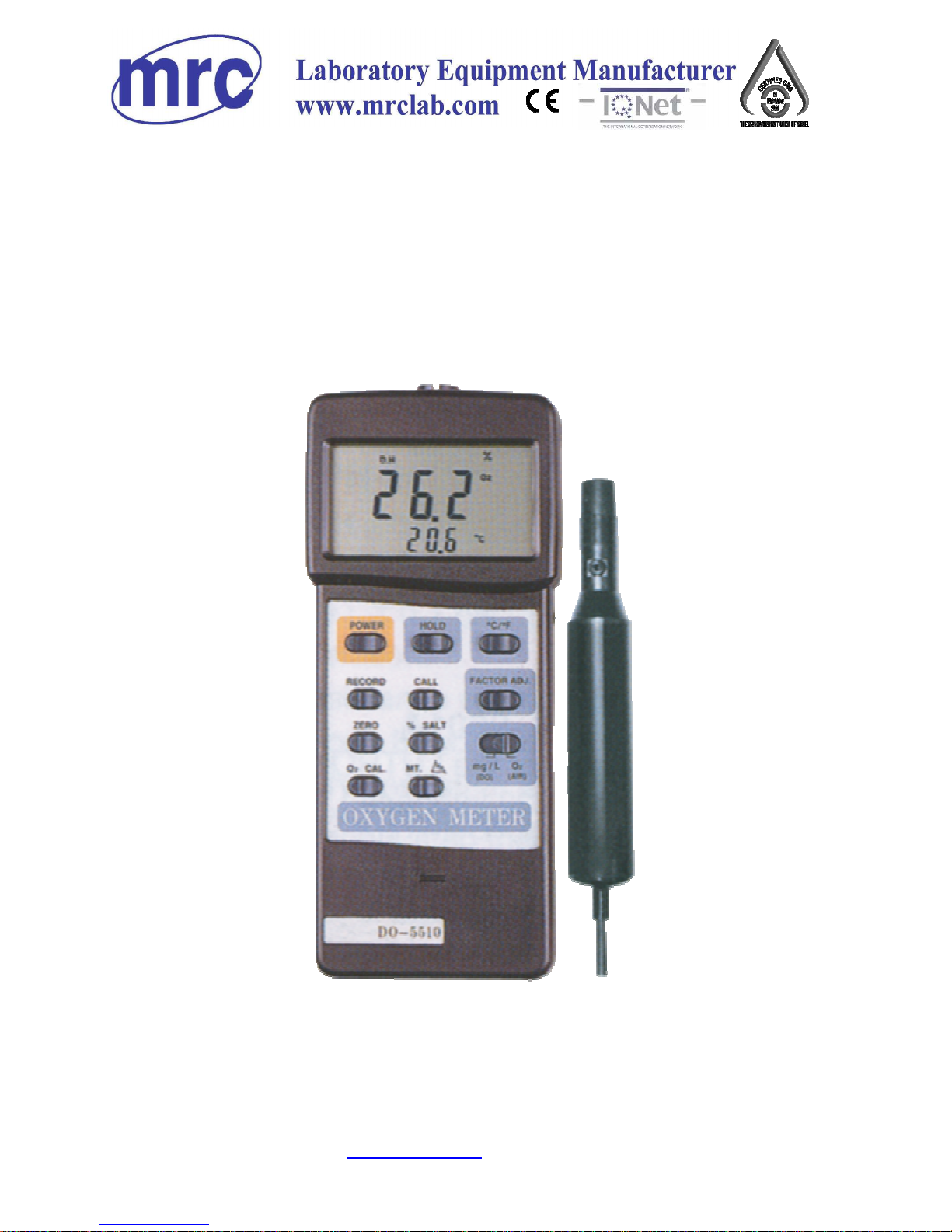
INSTRUCTION MANUAL FOR
DO-5510
DIGITAL OXYGEN METER
Page 2
ATTENTION :
Fill the Probe's Electrolyte at first.
Intend to keep the DO probe under
the best condition, when user receive
the DIGITAL OXYGEN METER along
the PROBE, it should fill the the
Probe's Electrolyte at first.
Probe-filling Electrolyte
`
Probe head with Diaphragm set
The procedures that to fill the Probe's
Electrolyte, refer the chapter 8
" PROBE MAINTENANCE ", page 13 .
Page 3

TABLE OF CONTENTS
1. GENERAL DESCRIPTIONS........................................................1
2. FEATURES.............................................................................
.
1
3. SPECIFICATIONS....................................................................2
4. FRONT PANEL DESCRIPTION..................................................
.
4
4-1 Display...........................................................................4
4-2 Power Off/On button......................................................
.
4
4-3 Data Hold button............................................................4
4-4 / button...................................................................℃℉ 4
4-5 LCD Contrast Ad
j
ust VR...................................................4
4-6 Memory Record button...................................................
.
4
4-7 Memory Call button........................................................
.
4
4-8 Factor Ad
j
. button...........................................................4
4-9 Zero button....................................................................4
4-10 % Salt button................................................................ 4
4-11 DO/O2 Selector..............................................................
.
4
4-12 O2 Cal. button................................................................4
4-13 MT. ( Mountain Hei
g
ht ) button........................................4
4-14 Battery Compartment/Cover............................................ 4
4-15 Probe Input Socket ........................................................
.
4
4-16 RS-232 Output Terminal..................................................4
4-17 Oxy
g
en Probe handle......................................................4
4-18 Temperature sensor........................................................4
4-19 Probe head with diaphra
g
m set........................................4
4-20 Protection cover for probe head.......................................4
4-21 Oxy
g
en probe plug..........................................................4
5. MEASURING PROCEDURE.......................................................
.
5
5-1 Calibration................................................................... 5
5-2 Dissolved Oxygen ( DO) measurement ..............................6
5-3 Oxy
g
en in Air ( O2) measurement .....................................8
5-4 Temperature measurement .............................................. 8
6.
AUTO POWER OFF DISABLE and LCD CONTRAST
ADJUSTMENT.........................................................................11
7. RS232 PC SERIAL INTERFACE................................................. 12
8. PROBE MAINTENANCE............................................................14
9. BATTERY REPLACEMENT....................................................... 16
Page 4

1. GENERAL DESCRIPTIONS
This Digital Oxygen Meter is supplied with a
polarographic type probe with an incorporated Temp.
sensor which serves for precise Dissolved Oxygen ( DO )
and Temp. measurement.
Applications for Aquarium, Medical research, Agriculture,
Fish hatcheries, Laboratory, Water conditioning, Mining
industry, Schools & Colleges, Quality control...
2. FEATURES
* The polarographic type oxygen probe with an incorpo-
rated Temp. sensor, high precision measurement for
Dissolved Oxygen ( DO ) and Temp. measurement.
* Heavy duty dissolved oxygen probe, probe head can
connect with BOD bottle
* Automatic Temp. compensation from 0 to 50 for sensor.℃
* Build in " % SALT " & " Mountain Height " compensation,
adjust the factor by push the button on the front panel.
* Microprocessor circuit assures high accuracy and provides
special functions and features.
* Super large LCD display with contrast adjustment for best
viewing angle.
* Multi-display, show oxygen & Temp. at the same time.
* Records Maximum, Minimum and Average readings with
recall, data hold.
1
Page 5
* Auto power off saves battery life.
* Powered by 006P DC 9V battery.
* RS 232 PC serial interface.
* Build in temperature , measurement.℃℉
* Use the durable, long-lasting components, including a
heavy duty & compact ABS-plastic housing case.
3. SPECIFICATIONS
Circuit Custom one-chip of microprocessor LSI
circuit.
Display Dual function meter's display, 13 mm ( 0.5" ).
Super large LCD display with contrast
adjustment for best viewing angle.
Measurement Dissolved Oxygen 0 to 20.0 mg/L ( liter ).
& Range Oxygen in Air 0 to 100.0 %.
Temperature 0 to 50 .℃
Dissolved Oxygen 0.1 mg/L.
Resolution Oxygen in Air 0.1 % O2 .
Temperature 0.1 .℃
Accuracy Dissolved Oxygen ± 0.4 mg/L.
(23± 5 )℃ Oxygen in Air ± 0.7% O2.
Temperature ± 0.8 /1.5 .℃℉
Sensor The polarographic type oxygen probe with
Structure an incorporated temperature sensor.
Probe Temperature 0 to 50 ,℃
Compensation Automatic
& Adj. Salt 0 to 39 % Salt
Height ( M. T.) 0 to 3900 meter
Memory Records Maximum, Minimum and
Recall Average readings with recall.
2
Page 6
Power off Auto power off saves battery life, or manual off
by push button.
Data Output RS 232 PC serial interface.
Over input Indication of "- - - -".
indication
Operating 0 to 50 (32 to 122 ).℃℃℉ ℉
Temperature
Operating Max. 80% RH.
Humidity
Sample Time Approx. 0.4 sec.
Power Supply 006P DC 9V battery ( Heavy duty type ).
Power Current Approx. DC 6.6 mA.
Weight 335 g/0.74 LB ( batteries & probe included )
Size Main instrument:
180 x 72 x 32 mm ( 7.1 x 2.8 x1.3 inch ).
Oxygen probe :
190 mm x 28 mm Dia. ( 7.5" x 1.1" Dia. )
Accessories Oxygen probe( OXPB-11 )................... 1 PC.
included Carryin
g
case..................................... 1 PC.
Operation manual...............................1 PC.
Spare Probe head with Diaphra
g
m
OXHD-04...........................................
.
2 set
Probe-fillin
g
Electrolyte
OXEL-03............................................
.
1 set
Optional * Oxygen probe.................................OXPB-11
Accessories * Spare Probe head with Diaphra
g
m set
..................................................... OXHD-04
* Probe-fillin
g
Electrolyte....................OXEL-03
* RS232 cable................................... UPCB-02
* USB cable.......................................USB-01
* Data Acquisition software
.............................................
.
SW-U801-WIN.
3
Page 7

4. FRONT PANEL DESCRIPTION
Fig. 1
4-1 Display 4-12 O2 Cal. button
4-2 Power Off/On button 4-13 MT. ( Mountain Height ) button
4-3 Data Hold button 4-14 Battery compartment/cover
4-4 / button℃℉ 4-15 Probe input socket
4-5 LCD Contrast Adjust VR 4-16 RS-232 input terminal
4-6 Memory record button 4-17 Oxygen Probe handle
4-7 Memory call button 4-18 Temperature sensor
4-8 Factor Adj. button 4-19 Probe head with diaphragm
4-9 Zero button 4-20 Protection cover for probe head
4-10 % Salt button 4-21 Oxygen probe plug
4-11 DO/O2 selector
4
Page 8

5 MEASURING PROCEDURE
5-1 Calibration
Before the measurement, the meter should be processed
the following calibration procedures:
1)Disconnect the " OXYGEN PROBE plug " ( 4-21, Fig. 1 )
from the " Probe input socket " ( 4-15, Fig. 1 ).
2)Power on the instrument by pushing the " Power Off/On
button " ( 4-2, Fig. 1 ).
3)Slide the " O2/DO selector " ( 4-11, Fig. 1 ) to the " O2 "
position.
Push the " Zero button " ( 4-9, Fig. 1 ) and the display
will show zero value.
4)Connect the " Oxygen probe plug " ( 4-21, Fig. 1 ) with
the " Probe input socket " ( 4-15, Fig. 1 ). Wait for
approx. 5 minutes at least until the display reading
values become stable & no fluctuation. Push the " O2
Cal. button " ( 4-12, Fig. 1 ) and the display will show
the values exactly same as 20.9 or 20.8. (As the
oxygen in air is 20.9 % typically, so use the
environment air 02 value for quick & precise
calibration).
Calibartion Consideration :
Please process calibration procedures under
wide and ventilating environment for best effect.
5
Page 9

5-2 Dissolved Oxygen ( DO) measurement
1)After the meter be calibrated ( above procedure 5-1 ),
the meter is ready for DO measurement.
2)Slide the " O2/DO selector " ( 4-11, Fig. 1 ) to the " DO "
position.
3)"% Salt" compensation of the probe :
a.Push the " % Salt button " ( 4-10, Fig. 1 )
first, and the display will show. :
0%
S
b.Push the " Factor Adj. button " ( 4-8, Fig. 1 ) once
will add " 1 % " to the original salt % value until the
adjusting reading reach the desired salt values.
Then push the " % Salt button " ( 4-10, Fig. 1 )
again to finish the adjusting procedures. At this
moment the new % salt values will be executed.
c. If the measured liquid is the pure water or the
factor of salt % can be neglected, then adjust %
salt compensation value to 0%.
4)"Height" compensation of the probe :
Bear in mind that the DO measurement is considered
to be taken at sea level. However if the measuring
environment is not at sea level ( 0 meter ), then
should adjust the " Height " values for the probe
compensation when make the DO measurement.
6
Page 10

a.Push the " MT ( Height) button " ( 5-13, Fig. 1 ) first,
then the display will show
0
H
b.Push the " Factor Adj. button " ( 4-8, Fig. 1 ) once
will add " 100 meters " to the original height values
until the adjusting reading reach the desired height
values ( meters ). Then push the " MT ( Height)
button " (4-13, Fig. 1) again to finish the adjusting
procedures. At this moment the new height values
(display unit is the " meters ") will be executed.
5)a. Immersed the probe to a depth at least 10 cm of
the measured liquid in order for the probe to be
influenced by the temperature & automatic
temperature compensation to take place.
b.As for the thermal equilibrium to occur between the
probe & the measurement sample must be allowed
to pass, which usually amounts to a few minutes if
the Temp. difference between the two is only
several Celsius degrees.
6)a. In order to measure the dissolved oxygen content in
any given liquid, it is sufficient to immerse the tip of
the probe in the solution, making sure that velocity
of the liquid coming into contact with the probe is at
least 0.2 - 0.3 m/s or to shake the probe.
b.During laboratory measurements, the use of a
magnetic agitator to ensure a certain velocity in the
fluid is recommended. In this way, errors due to the
diffusion of the oxygen present in the air in the
solution are reduced to a minimum.
7
Page 11

7)Rinsed the probe accurately with normal tap water after
each series of measurement.
5-3 Oxygen in Air ( O2 ) measurement
1)After the meter be calibrated ( above procedure 5-1 ),
now the meter is ready for O2 measurement.
2)Slide the " O2/DO selector " ( 4-11, Fig. 1 ) to the " O2 "
position.
3)The display will show the air oxygen in % values.
5-4 Temperature measurement
During the measurement, the lower LCD Display will
show the temperature values of measuring solution.
* Push the " / button " ( 4-4, Fig. 1 ) once to select℃℉
measuring unit in or .℃℉
5-5 Data Hold
During the measurement, Push the " Data Hold button "
( 4-3, Fig. 1 ) will hold the display values & LCD will
show the " D.H " marker.
* Push the " Data Hold button " again will exit the
data hold function.
5-6 Data Record( Max., Min., Average reading)
* The DATA RECORD function displays the
maximum, minimum and average readings. To start
the DATA RECORD function, press the " Memory
Record button " ( 4-6, Fig. 1 ) once. " REC " symbol
will appear on the LCD display.
8
Page 12

* With the " REC " symbol on the display :
(a) Push the " Memory CALL button " ( 4-7, Fig. 1 )
once, the " Max " symbol along with the maximum
value will appear on the display.
(b) Push the " Memory CALL button " again, the " Min "
symbol along with the minimum value will appear
on the display.
(c) Push the " Memory CALL button " again, the
" AVG " symbol along with the average value will
appear on the display.
(d) To exit the memory record function, push the
" RECORD " button once again. The display will
revert back to the current reading.
5-7 Quick operation procedures :
Calibration procedures
Power on, slide the " DO/O2 selector " to " O2 " position.
Disconnect the probe from the meter.
Push the " Zero button ", display will show zero.
Connect the probe to the meter. Until the display reading
reach the stable values ( approx. 5 minutes ). Push the " O2
Cal. " position, then display will show 20.9.
9
Page 13

Dissolved Oxygen ( DO ) measurement
procedures
Power on, after calibration procedures be executed.
Slide the " DO/O2 selector " to " DO " position.
Determine the " % Salt " & " Height " values.
* For the general application, it is not necessary to make
the adjustment for the " % salt " & " Height " values.
Immerse the probe head into the measured liquid.
Other function :
DATA HOLD MEMORY RECORD RS232 output
Max., Min., AVG
Power management
AUTO POWER OFF or MANUAL POWER OFF
Not available in
Memory Record function
10
Page 14

6. AUTO POWER OFF DISABLE
and LCD CONTRAST ADJUS
T
1)The instrument has built-in "Auto Power off "
in order to prolong battery life. The meter will switch
off automatically if none of the buttons are pressed
within 10 min.
To de-activate this feature, select the memory record
function during measurement by pressing the
" RECORD " button ( 4-6, Fig. 1 ).
2)The instrument also features the ability to adjust the
contrast of the display.
This is achieved by controlling the " LCD Contrast
Adjust " pot ( 4-5, Fig. 1 ).
11
Page 15

7. RS232 PC SERIAL INTERFACE
The instrument features an RS232 output via 3.5 mm
Terminal ( 4-16, Fig. 1). The connector output is a 16
digit data stream which can be utilized to the user's
specific application.
An RS232 lead with the following connection will
be required to link the instrument with the PC
serial input.
Meter PC
(3.5 mm jack plug) (9W 'D" Connector)
Center Pin..........................................Pin 2
Ground/shield........................................Pin 5
The 16 digit data stream will be displayed in the
following format :
D15 D14 D13 D12 D11 D10 D9 D8 D7 D6 D5 D4 D3 D2 D1 D0
12
Page 16

Each digit indicate the following status :
D15 Start Word =02
D14 Reading Polarity for the Display.
0 =Both upper & lower display value are "+".
1 =Upper "-", Lower "+".
2 =Upper "+", Lower "-".
3 =Both upper & lower display value are "-".
D13 Anunuciator for Lower Display
0 =No Symbol 1 =℃ 2 =℉
D12 & D11 Anunuciator for Upper Display
01 =℃ 07 =mg/L
02 =℉ 06 = % O2
D10 Decimal Point (DP) for lower display
0 = No DP, 1= 1 DP, 2 = 2 DP, 3 = 3 DP
D9 Decimal Point ( DP) for Upper display.
0 = No DP, 1= 1 DP, 2 = 2 DP, 3 = 3 DP
D8 to D5 Lower Display reading, D5=LSD, D8=MSD
D4 to D1 Upper Display reading, D1=LSD, D4=MSD
D0 End Word = 0D
RS232 setting
Baud rate 9600
Parity No parity
Data bit no. 8 Data bits
Stop bit 1 Stop bit
13
Page 17

8. PROBE MAINTENANCE
User first time to use the meter :
Intend to let the DO probe keep the best
condition. When user receive the DIGITAL
OXYGEN METER along the PROBE, it should
fill the Probe's Electrolyte at first.
User already use the meter for a certain
period :
Whenever user can not calibrate the meter
properly or the meter's reading value is not stable,
please check the oxygen probe to see if the
electrolyte in the probe head container is run out
or the diaphragm ( probe head with diaphragm
set) exist problem ( dirty ). If yes, please fill the
electrolyte or change the " Probe head with
diaphragm set " and make the new calibration.
The consideration of Diaphragm ( probe head
with diaphragm set) :
The oxygen probe component is the thin Teflon
diaphragm housed in the tip of the probe. The
diaphragm is permeable by the oxygen molecules but
not by the considerably larger molecules contained in
the electrolyte. Due to this characteristic, the oxygen
may diffuse throughout the electrolyte solution
contained in the probe, and its concentration may be
quantified by the measurement circuit.
14
Page 18

This sensitive diaphragm is rather delicate & is easily
damaged if it comes into contact with solid objects or is
subjected to blows. If the diaphragm is damaged or the
electrolyte is run out, it must be replaced in the following
way :
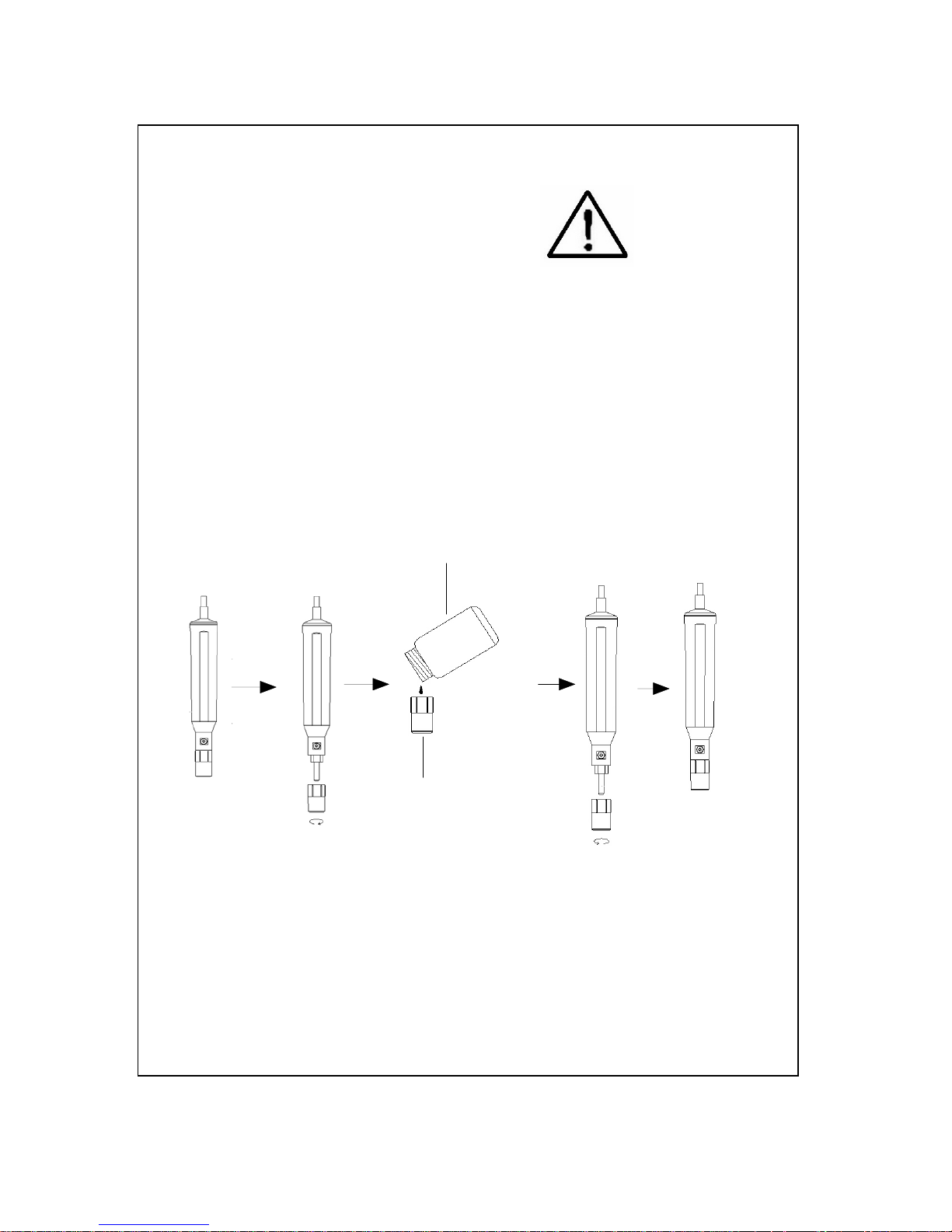
Probe-filling Electrolyte,
OXEL-03
Probe head with Diaphragm set
1)Unscrew the " Probe head " ( 8-3, Fig 2 ).
2)Pour out the old Electrolyte from the
container of the " Probe head ".
3)Fill the new Electrolyte ( OXEL-03 )
into the container of the " Probe
head " .
4)Screw the " Probe head " ( 8-3, Fig 2 )
into the probe body.
Fig. 2
8-1 Probe handle
8-2 Temp. sensing metal
8-3 Probe head
15
Page 19

9. BATTERY REPLACEMEN
T
1)When the left corner of LCD display show " LBT ", it is
necessary to replace the battery. However, in-spec
measurement may still be made for several hours
after low battery indicator appears.
2)Slide the " Battery Cover " ( 4-14, Fig. 1 ) away from
the instrument and remove the battery.
3)Replace with 9V battery (heavy duty type) and
reinstate the cover.
4)Make sure the battery cover is secured after changing
the battery.
16
3, Hagavish st. Israel 58817 Tel: 972 3 5595252, Fax: 972 3 5594529
mrc@mrclab.com
 Loading...