

Page 1
CURRENT,VOLTAGE,Type K
CALIBRATOR
Model : CC-423
Your purchase of this 3 in 1
CALIBRATOR METER
with Source & Measurement
marks a step forward for you
into the field of
precision measurement.
Although this meter a
complex and delicate
instrument, its durable
structure will allow
many years of use if
proper operating
techniques are
developed. Please read
the following
instructions carefully
and always keep this
manual within easy
reach.
OPERATION MANUAL
PLEASE READ THIS MANUAL CAREFULLY BEFORE OPERATION
3, Hagavish st. Israel 58817 Tel: 972 3 5595252, Fax: 972 3 5594529 mrc@mrclab.com
MRC.1.18
Page 2

TABLE OF CONTENTS
1. FEATURES...........................................................................................................................................................
2. SPECIFICATIONS..............................................................................................................................................
3. FRONT PANEL DESCRIPTION........................................................................................................................................
4. SOURCE PROVIDE PROCEDURE..........................................................................................................................................
4-1. CURRENT SOURCE PROVIDE PROCEDURE ....................................................................................................................................................................................
4-2. VOLTAGE SOURCE PROVIDE PROCEDURE ..........................................................................................................................................
4-3. Type K SOURCE PROVIDE PROCEDURE .....................................................................................................................................................................
5. MEASUREMENT PROCEDURE..........................................................................................................................................
5-1. CURRENT MEASURE PROCEDURE.............................................................................................................
5-2. Power and current measurement of two wire loop Procedure..........................................................................
5-2. Type k MEASURE PROCEDURE ..........................................................................................................................................
6. ADVANCED SETTING....................................................................................................................................................
6-1 Auto power OFF management ..........................................................................................................................................
6-2 Select the Temp. unit to
or ℉...........................................................................................................................................................................................
7. POWER SUPPLY from DC ADAPTER...........................................................................................................................
8. BATTERY REPLACEMENT...................................................................................................................................
9. SYSTEM RESET.......................................................................................................................................................
℃
1
1
5
6
6
6
7
7
7
7
8
8
9
9
10
10
10
Page 3
1. FEATURES
*
Multi-Source output :
1. Current source, 2. Voltage source,
3. Type K Temp. source.
*
Three kinds measurement function :
1. Current measurement, 2. Power and current measurement,
3. Type K Temp. measurement.
* Portable instrument for calibrating process devices.
* Adjustable 0-24 mA current source.
* Current calibrator drives loads up to 500 ohms.
* Four function provide the quality and accuracy of handheld
calibrator of precision current source.
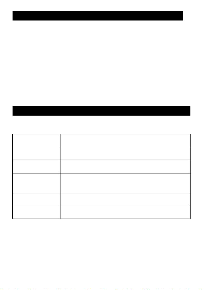
2. SPECIFICATIONS
2-1 General Specifications
Circuit Custom one-chip of microprocessor LSI
circuit.
Display LCD size : 52 mm x 30 mm.
LCD with white backlight ( ON/OFF ).
Measurement Current :Max. 24 mA.
Type k Temp : - 199.9 to 1370.0 ℃.
Source
Sampling Time Approx. 1 second.
of Display
Advanced
setting
Current : 0 to 24.00mA .
Voltage (DC mV : - 200.0 to + 200.0 mV).
Type k Temp : - 199.9 to 1370.0 ℃.
* Auto power OFF management.
*
Set unit ℃ or ℉ .
1
Page 4
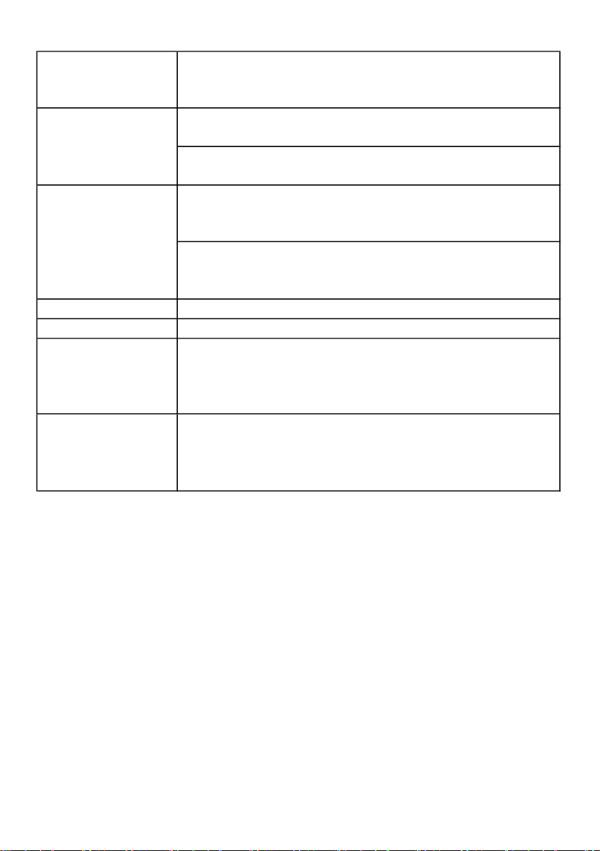
Operating 0 to 50 ℃.
Instruction manual..............................................
Hard carrying case( CA-06 ).....................................................
V, A cable LN-TL421.........................................
Type K source cable AC-DUK02.........................................
Temperature Less than 85% R.H.
and Humidity
Power Supply * Alkaline or heavy duty DC 1.5 V battery
( UM3, AA ) x 6 PCs, or equivalent.
* DC 9V adapter input. ( AC/DC power
adapter is optional ).
Power Current Normal operation ( w/o current source ) :
Approx. DC 18 mA.
(LCD Backlight is ON) : Approx. + DC 5 mA.
Current source (under 10 mA signal out put) :
Approx. DC 33 mA.
(Backlight is ON) : Approx. + DC 5 mA.
Weight Meter : 306 g/ 0.67 LB. (with cable)
Dimension Meter : 178 x 68 x 45 mm
Accessories *
Included *
*
*
Optional
Accessories AC to DC 9V adapter.
TP-01,TP-02A, TP-03, TP-04, TP-05
1 PC
1 PC
1 PC
1 PC
2
Page 5

2-2 Electrical Specifications (23. 0 ± 5 ℃)
V
oltage
source
0.1 m
V
T
ype k
source
30 MHz only.
Current source
Current source
Range Display Accuracy
Resolution
0.05 - 24.00 mA 0.01 mA
* Output 0-20 mA current for loads up to 500 ohms.
Output > 20 mA current for loads up to 400 ohms.
* FS : full scale
Voltage source
Range Display Accuracy
Resolution
-199.9 mV to +199.9 mV
* Output measured load inpedence should > 1 K ohms.
Type k source
±( 0.25 % FS )
±( 0.25 % FS +0.2mV)
Range Display Accuracy
Resolution
-199.9 to 1370.0 ℃
-327.0 to 2498.0 ℉
* intput inpedence : 10 ^12 ohms.
Remark :
The above specification are tested under the environment
RF Field Strength less than 3 V/M & frequency less than the
0.1 degree
0.1 degree
> -100℃ ±( 0.1 % FS + 1 ℃ )
< -100℃ ±( 0.1 % FS + 2 ℃ )
> -148℉ ±( 0.1 % FS + 2 ℉ )
< -148℉ ±( 0.1 % FS + 4 ℉ )
3
Page 6

Current measure
Current
measure
0 - 24.00 mA
0 - 24.00 mA
Range Display Accuracy
Resolution
0.01 mA ±( 0.25 % FS + 1 d )
* input load 10 ohm
* FS : full scale
Power and current measurement of two wire loop
Power and current measurement of two wire loop
Range Display Accuracy
Resolution
0.01 mA ± ( 0.25 % FS + 1 d )
*Provides power DC 12V ±2V to the loopand measures
* input load 10 ohm
* FS : full scale
Type k measure
Type k measure
Range Display Accuracy
Resolution
-199.9 to 1370.0 ℃
-327.0 to 2498.0 ℉
* intput inpedence : 10 ^12 ohms.
0.1 degree
0.1 degree
± ( 0.1 % FS + 1.0 ℃ )
± ( 0.1 % FS + 2.0 ℉ )
Remark :
The above specification are tested under the environment RF Field
Strength less than 3 V/M & frequency less than the 30 MHz only.
CAUTION
* Do not apply a voltage exceeding the maximum input voltage.
otherwise the input part may be damaged.
* Do not short_circuit or apply an extenal voltage to output terminals of the
instrument or standard equipment, or else their internal circuitry may be
damaged.
4
Page 7

3. FRONT PANEL DESCRIPTION
3-5 ▲ Button
3-6 ▼ Button
Fig. 1
3-1 Display
3-2 ◄ button ( Backlight Button)
3-3 Power Button
3-4 ► button
3-7 FUNCTION Button
3-8 Source/Measure Button
3-10 Reset Button 3-19 Red Alligator clip
3-11 DC 9V Power Adapter Input Socket
3-12 Battery Cover Screws
3-13 Tripod Fix Nut
3-14 Stand
3-15 Battery Compartment/Cover
3-16 Type K Temp.Input Socket
3-17 Cable 4 DIN Socket
3-18 Cable 4 DIN Plug
3-20 Black Alligator clip
5
Page 8

4. SOURCE PROVIDE PROCEDURE
Power on the meter by press
the " Power
button
" ( 3-
3,Fig. 1 ) > 2 sec.
Press the " FUNCTION
button " ( 3-7, Fig. 1 ) select to Current
Function
.
Press the "
button "( 3-6, Fig. 1 ) or "
button "( 3-5, Fig. 1 ) to adjust
the value of the digit. Press and Hold the
or ▲ button to rapidly adjust
Power on the meter by press
the " Power
button
" ( 3-
3,Fig. 1 ) > 2 sec.
Press the " FUNCTION
button " ( 3-7, Fig. 1 ) select to voltage
Function
.
4-1. CURRENT SOURCE PROVIDE PROCEDURE
1)
2) Press the " Source/Measure Button " ( 3-8, Fig. 1 ) select to SOURCE
Model .
3)
4) Press the " ► button "( 3-4, Fig. 1 )or " ◄ button"( 3-2, Fig. 1 ) select
a digit for adjustment. The blinking digit identifies the digit selected.
5)
the value. And will generate the current output same as the display value.
Remark :
The " Red Alligator clip " ( 3-19, Fig. 1 ) is for the positive
current output. The " Black Alligator clip " ( 3-20, Fig. 1 ) is
the " ground " for current output.
▼
▲
▼
4-2. VOLTAGE SOURCE PROVIDE PROCEDURE
1)
2) Press the " Source/Measure Button " ( 3-8, Fig. 1 ) select to SOURCE
Function .
3)
4) Press the " ► button "( 3-4, Fig. 1 )or " ◄ button"( 3-2, Fig. 1 ) select
a digit for adjustment. The blinking digit identifies the digit selected.
5)
Press the " ▼button "( 3-6, Fig. 1 ) or " ▲button "( 3-5, Fig. 1 ) to adjust the
value of the digit. Press and Hold the ▼ or ▲ button to rapidly adjust the
value. And will generate the voltage output same as the display value.
6
Page 9

4-3. Type K SOURCE PROVIDE PROCEDURE
Press the "
button "( 3-6, Fig. 1 ) or "
button "( 3-5, Fig. 1 ) to adjust the
value of the digit. Press and Hold the
or ▲ button to rapidly adjust the
1) Power on the meter by press the " Power button " ( 3-3,Fig. 1 ) > 2 sec.
2) Press the " Source/Measure Button " ( 3-8, Fig. 1 ) select to SOURCE
Model .
3) Press the " FUNCTION button " ( 3-7, Fig. 1 ) select to Type K Function.
4) Press the " ► button "( 3-4, Fig. 1 )or " ◄ button"( 3-2, Fig. 1 ) select
a digit for adjustment. The blinking digit identifies the digit selected.
5)
value. And will generate the Type k Temp. output same as the display value.
▼
▲
▼
5. MEASUREMENT PROCEDURE
5-1. CURRENT MEASURE PROCEDURE
1) Power on the meter by press the " Power button " ( 3-3,Fig. 1 ) > 2 sec.
2) Press the " Source/Measure Button " ( 3-8, Fig. 1 ) select to MEASURE
Model .
3) Press the " FUNCTION button " ( 3-7, Fig. 1 ) select to CURRENT
Measure Function.
4) The " Red Alligator clip " ( 3-19, Fig. 1 ) connect to the positive,
the " Black Alligator clip " ( 3-20, Fig. 1 ) connect to the " ground " for
current intput.
5) The meter LCD display will show the measure value same as the input
current value.
Remark :
The current input Max. 24 mA.
5-2. Power and current measurement of two wire loop Procedure
7
Page 10

Fig. 2
5-3. Type k MEASURE PROCEDURE
Remark : The Type k temp. input Max. 1370
.
1) Power on the meter by press the " Power button " ( 3-3,Fig. 1 ) > 2 sec.
2) Press the " Source/Measure Button " ( 3-8, Fig. 1 ) select to
Measure Model .
3) Press the " FUNCTION button " ( 3-7, Fig. 1 ) select to Power/mA
Measure Function.
4) Open the circuit in which current connect is to be measured and connect
the " Red Alligator clip " ( 3-19, Fig. 1 ) and " Black Alligator clip "
( 3-20, Fig. 1 ) securely in series with the load in which the current is be
measured .
Note:
a. The " Red Alligator clip " ( 3-19, Fig. 1 ) is for the positive current
measurement input .
The " Black Alligator clip " ( 3-20, Fig. 1 ) is for the negative current
measurement input .
b. The measuring procedures & principal are same as the 5-1 Current
measurement except the meter build in the DC 12 V power source
in serial with the current meter ,please refer Fig. 2 .
1) Power on the meter by press the " Power button " ( 3-3,Fig. 1 ) > 2 sec.
2) Press the " Source/Measure Button " ( 3-8, Fig. 1 ) select to
MEASURE Model .
3) Press the " FUNCTION button " ( 3-7, Fig. 1 ) select to Type k Measure
Function.
4) The Type k Temp. probe into the " Type k Temp. socket " ( 3-16, Fig. 1 ) .
5) The meter LCD display will show the measure value same as the input
Type k temp. value.
℃
8
Page 11

6. ADVANCED SETTING
POFF.......
℉
Under do not execute the Datalogger function, press the " Function
Button " ( 3-7, Fig. 1 ) continuously at least 3 seconds will enter the "
Advanced Setting " mode. Then press the " Function Button "
(3-7, Fig. 1 ) once a while in sequence to select the two main function,
the lower display will show :
Auto power OFF management
t-CF.......
Remark :
During execute the " Advanced Setting " function, if press
" POWER Button " ( 3-3, Fig. 1 ) once will exit the " Advanced
Setting " function, the LCD will return to normal screen.
6-1 Auto power OFF management
When the lower display show " PoFF "
1)
Use the " ▲ Button " ( 3-5, Fig. 1 ) or " ▼ Button "( 3-6, Fig. 1 )
to select the upper value to " yES " or " no ".
yES - Auto Power Off management will enable.
no - Auto Power Off management will disable.
Select the Temp. unit to ℃ or
2) After select the upper text to " yES " or " no ", press the " Source/Measure
Button " ( 3-8, Fig. 1 ) will save the setting function with default.
6-2 Select the Temp. unit to ℃ or
When the lower display show " t-CF "
1)
Use the " ▲ Button " ( 3-5, Fig. 1 ) or " ▼ Button " ( 3-6, Fig. 1 )
to select the upper Display text to " ℃ " or " ℉ ".
C - Temperature unit is ℃
F - Temperature unit is ℉
2)
After Display unit is selected to " ℃ " or " ℉ ", press the " Source/Measure
Button " ( 3-8, Fig. 1 ) will save the setting function with default.
℉
9
Page 12

7. POWER SUPPLY from DC ADAPTER
The meter also can supply the power supply from the
DC 9V Power Adapter ( optional ). Insert the plug of
Power Adapter into " DC 9V Power Adapter Input Socket
" ( 3-11, Fig. 1 ). The meter will auto select to DC 9V Power Adapter .
8. BATTERY REPLACEMENT
1) When the left corner of LCD display show " ", it
is necessary to replace the battery. However, in-spec.
measurement may still be made for several hours after
low battery indicator appears before the instrument
become inaccurate.
2) Loose the screws of the " Battery Cover Screws " ( 3-12,
Fig. 1 ) and take away the " Battery Cover " ( 3-15, Fig. 1 )
from the instrument and remove the battery.
3) Replace with DC 1.5 V battery ( UM3, AA,
Alkaline/heavy duty ) x 6 PCs, and reinstate the cover.
4) Make sure the battery cover is secured after changing
the battery.
9. SYSTEM RESET
If the meter happen the troubles such as :
CPU system is hold ( for example, the key button can
not be operated... ).
Then make the system RESET will fix the problem.
The system RESET procedures will be either following
method :
During the power on, use a pin to press the " Reset
Button " ( 3-10, Fig. 1 ) once a while will reset the
circuit system.
10
 Loading...