

Page 1

Page 2

- 2 -
JULY 2010
Page 3

- 3 -
Contents
1. UNWRAPING THE BALANCE ..................................................................5
1.1. The balance ASB/X..................................................................................5
2. START THE BALANCE UP.......................................................................6
2.1. Conditions of proper usage....................................................................6
2.2. Set level up............................................................................................6
2.3. Warming up ...........................................................................................6
3. APPROPRATION.......................................................................................7
4. DESCRIPTION OF THE BALANCE - display...........................................8
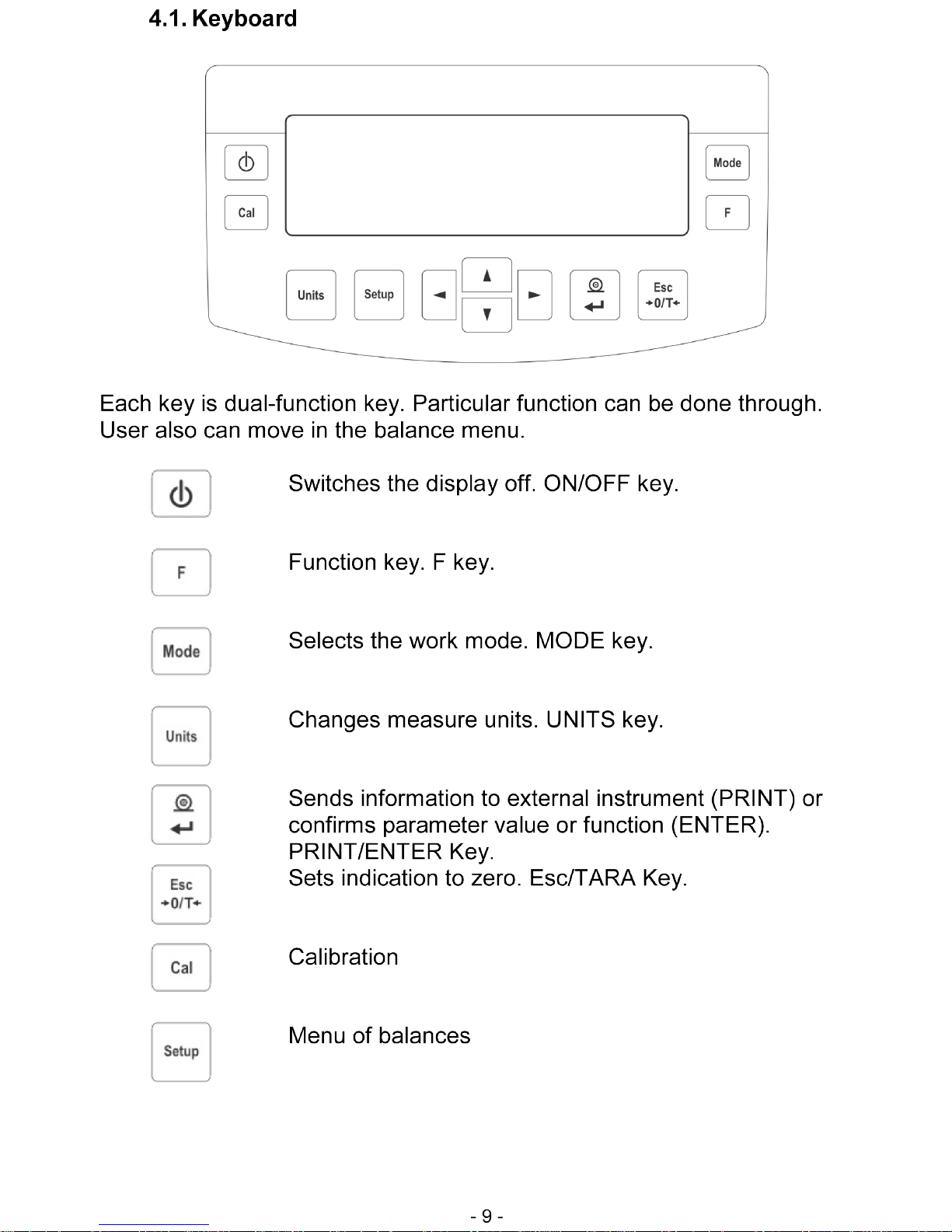
4.1. Keyboard ...............................................................................................9
4.2. Connections.........................................................................................10
5. USER MENU............................................................................................10
5.1. Move in user menu..............................................................................13
5.1.1. The balance keyboard...................................................................14
5.1.2. Return to weighing function...........................................................14
5.1.3. PS computer keyboard..................................................................15
5.1.4. By means of virtual keyboard through RS 232..............................16
5.2. User menu...........................................................................................16
6. WEIGHING...............................................................................................17
6.1. Log-in function.....................................................................................18
7. BALANCE CALIBRATION ......................................................................21
7.1. Automatic balance calibration..............................................................21
7.2. Calibration test.....................................................................................23
7.3. Manual calibration................................................................................24
7.3.1. Internal calibration.........................................................................24
7.3.2. External calibration........................................................................24
7.3.3. Calibration performed by user.......................................................25
7.3.4. Calibration report printout..............................................................26
8. SETTING PRINTOUTS FOR GLP PROCEDURES.................................27
9. SETTING TIME AND DATE.....................................................................27
10. SETTING THE PARAMETERS................................................................30
10.1. Setting filter.....................................................................................30
10.2. Value release..................................................................................31
10.3. Set the display refreshing time........................................................31
10.4. Set autozero working......................................................................31
10.5. Last digit..........................................................................................31
10.6. Negative..........................................................................................32
11. FUNCTIONS IN USING RS 232 PORT....................................................32
12. PRINTOUTS.............................................................................................33
13. ACCESS TO MASS UNITS 33
Page 4

- 4 -
14. SETTING ACCESSIBILITY OF THE WORK MODES.............................34
15. OTHER PARAMETERS...........................................................................34
16. USING WORK MODES............................................................................36
16.1. Countign pieces of the same mass.................................................36
16.1.1. Counting pieces after writing piece mass......................................37
16.1.2. Counting through determine singular element mass from the
standard batch.............................................................................................38
16.1.3. Select piece from date base..........................................................40
16.2. Checkweighing................................................................................40
16.3. Filling ..............................................................................................42
16.4. Percents..........................................................................................43
16.5. Weighing animals............................................................................46
16.6. Density of solids and liquids............................................................47
16.6.1. Density of liquids...........................................................................47
16.6.2. Density of solids............................................................................48
16.7. Formulation.....................................................................................48
16.8. Statistics..........................................................................................53
17. KINDS OF PRINTOUTS...........................................................................55
17.1. Standard printout ............................................................................55
17.2. Non-standard printout.....................................................................56
17.2.1. Texts..............................................................................................57
17.2.2. Composing texts by Edition function .............................................62
17.2.3. Select non-standard printouts........................................................63
18. COOPERATION WITH PRINTER OR COMPUTER................................64
18.1. Connections....................................................................................64
19. COOPERATION WITH LABEL PRINTERS CITIZEN CLP-521...............65
20. WEIGHING LOADS UNDER THE BALANCE.........................................70
21. CONNECTING ADDITIONAL KEYS........................................................71
22. LIST OF COMMUNICATIONS COMPUTER - BALANCE.......................71
23. TECHNICAL PARAMETERS...................................................................74
24. COMMANDS ABOUT ERRORS..............................................................74
Page 5
- 5 -
1. UNWRAPING THE BALANCE
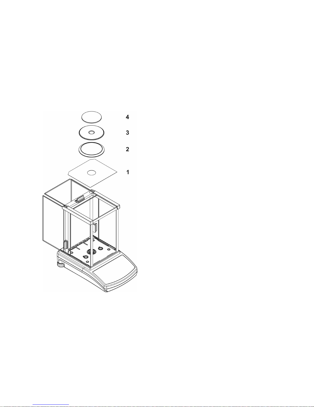
1.1. The balance ASB/X
Cut safety tape off. Take balance off the box. Take all necessary to
correct performance of balance elements off the box. After replace
balance in place of use put scale and rest of elements on.
− open side doors of weighing
chamber,
− inside the chamber place lower
shield of weighing chamber (1),
− inside the chamber place anti-
breeze shield (2),
− put centring ring on the shield
(3),
− put the balance pan inside the
ring (4),
− close side doors of weighing
chamber,
− turn on balance supply,
− pin of power adaptor should be
connected to socket in the back
of balance casing.
.Draw 1. The components installation for the WAS X balance with d=0,1mg
The balance is supplied through power pack 110-230 V AC / 13,8 V DC.
Power pack socket is at the rear of the balance.
Page 6

- 6 -
2. START THE BALANCE UP
2.1. Conditions of proper usage
− Set the balance on stable table, far from vibrations
− The balance should be replaced far from draughts and air breeze.
− The balance should be in stable temperature and humidity room
− The balance should be replaced far from sources of
− Temperature in the room +18°C ÷ +30°C ( ASB/X)
− If the static electricity has influence on the balance indications it
base should be earthed. Earthing screw is in the rear part of the
balance base.
− The balance should be replaced in leveled position
2.2. Set level up
The balance should be leveled. The correct leveling is shown on the level
indication installed at rear of the balance.
2.3. Warming up
Before measurements user should wait untill the balance reaches
temperature stabilization. It is warming up time.
For analytical balances warming-up time is about 1 hour.
This periods refers to the balances which ware in surrounding temperature
(work) before start weighing.
If the analytical balances are kept in lower temperature before
weighing the warming-up time is about 8 hours and for precision balances it
is about 2 hours.
During warm-up stabilization the indications can change.
Page 7
- 7 -
3. APPROPRATION
The balances are used to do precise measurements in laboratories. It is
possible to do the zero function in all measure range.
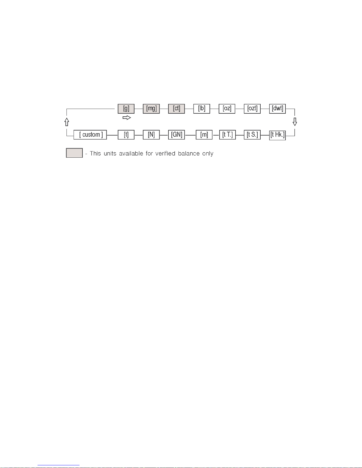
The balance weights in following units:
Draw 2. Measure units
Apar
t from weighing in various measure units the balance also:
− counts pieces
− weights
− dosages
− determines deviations of the standard mass
− weights animals
− detemines liquids and solids density
− formulation
− creates statistics
Measure units and particular functions can be inaccessible for user. It
is possible to adapt the balance to individual needs and access functions
and units which are necessary at this moment.
It is possible to define accessible or noo-accessible in user menu and it
is described in further part of the manual.
Page 8
- 8 -
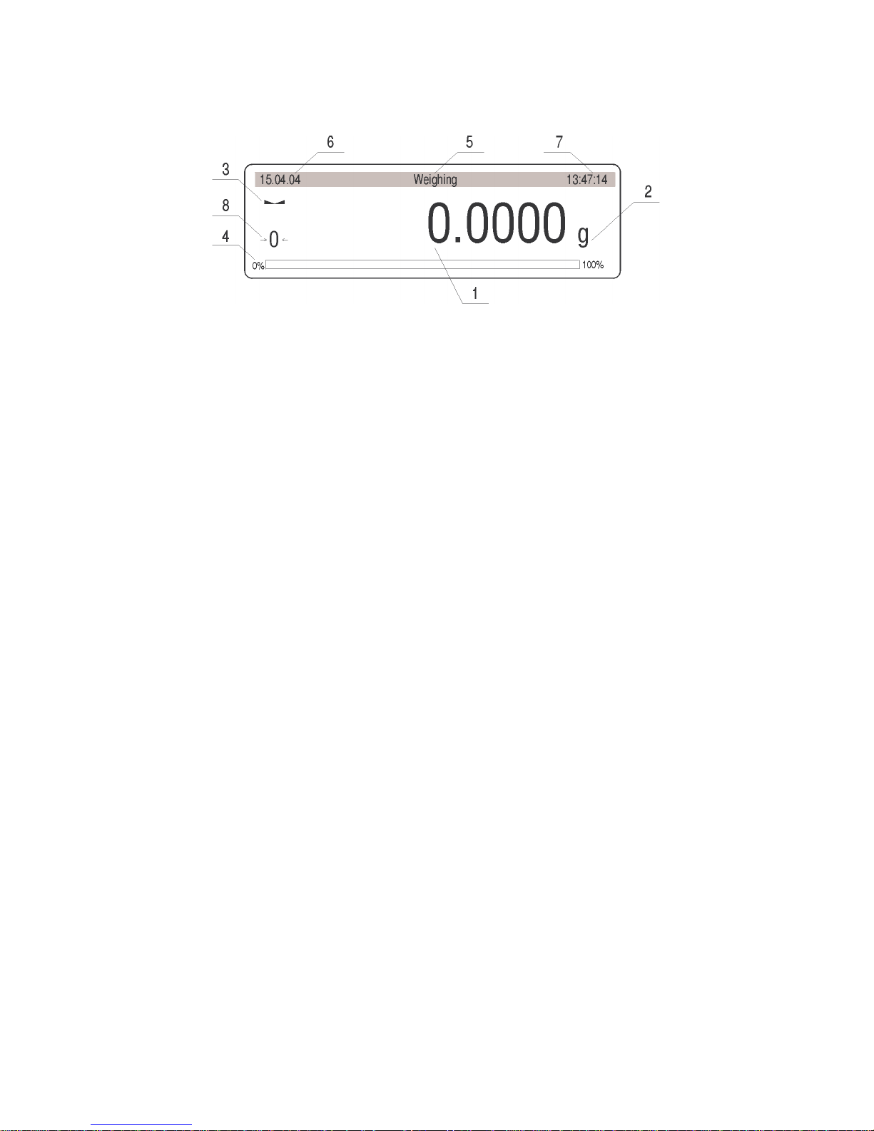
4. DESCRIPTION OF THE BALANCE - display
Draw 3. Display balance
1. load mass and quantity of pieces
2. measure unit
3. the result is stable
4. line of max range of the balance
5. work mode
6. date
7. time
8. precise ZERO
Page 9
Page 10
- 10 -
Navigation bar
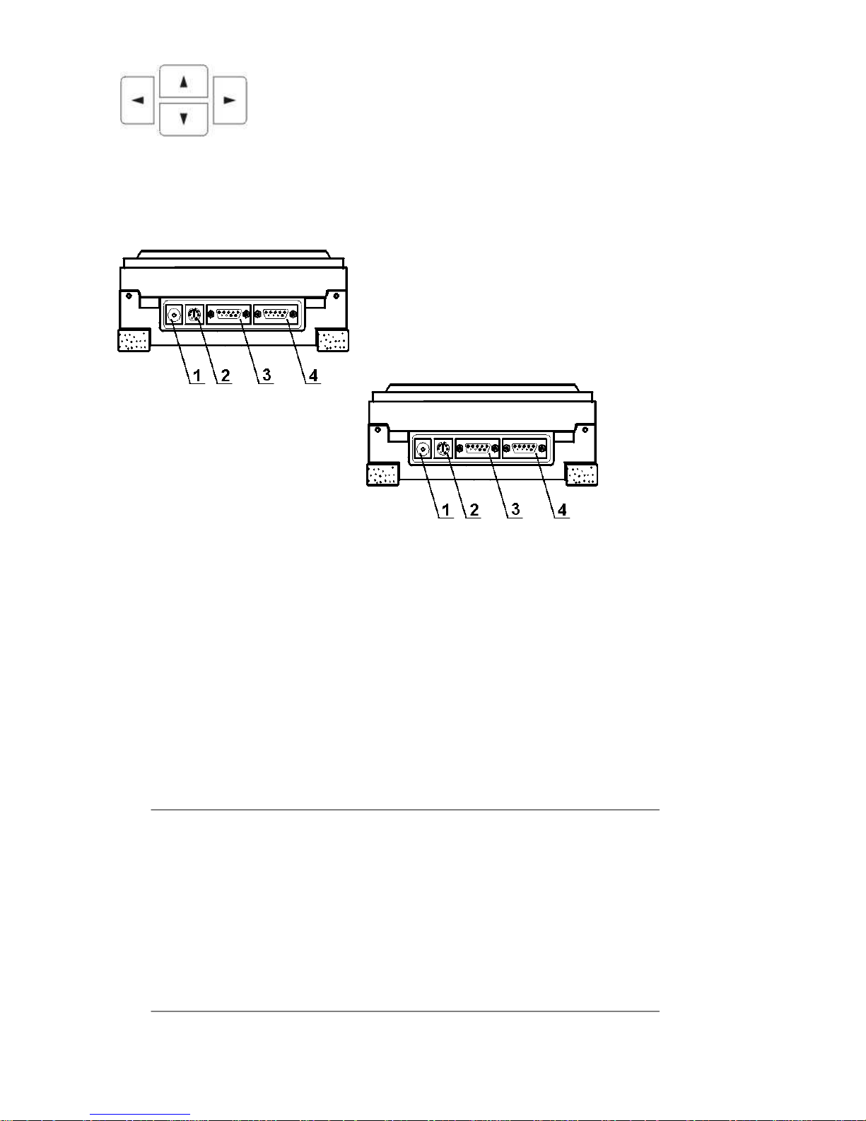
4.2. Connections
1. power adapter socket
2. PS keyboard connector
3. RS 232 port
4. additional display socket
Draw 4. Sockets of the WPX bala
nce
5. USER MENU
There are 9 groups in user menu. Each
group is named by P letter. Name and contents of each group is presented
below.
P1 Calibration
01 Int. calibr |
* * * * * * * *
| function
02 Ext. calibr |
* * * * * * * *
| function
03 User calibr |
* * * * * * * *
| function
04 Calibr test |
* * * * * * * *
| function
05 Weight corr. | * * * * * *0.0 |
06 Auto calibr | * * * * * *0.3 | both
07 Auto cal time | * * * * * *0.3 | 3 hours
08 Print report | * * * * * *0.1 | on
P2 GLP
01 User | Nowak Jan |
02 Project | AR – 65/04 |
03 Time print | * * * * * *0.0 | off
04 Da
te prin | * * * * * *0.0 | off
05 User print | * * * * * *0.0 | off
06 Pro
ject print | * * * * * *0.0 | off
07 Id print | * * * * * *0.0 | off
08 Last cal print | * * * * * *0.0 | off
P3 Date/Time
Page 11

- 11 -
01 Date format | * * * * * * * 0 | DA/MO/YR
02 Time format | * * * * * * * 0 | 24 hours
03 Time |
* * * * * * * *
| Function
04 Date |
* * * * * * * *
| Function
05 Disp. time | * * * * * * * 1 | on
06 Disp. date | * * * * * * * 1 | on
P4 Readout
01 Filter | * * * * * * * 3 | normal
02 Value relase | * * * * * * * 1 | fast + rel
03 Disp. Refresh | * * * * * * * 1 | 0.1 s
04 Autozero | * * * * * * * 1 | on
05 Last digit | * * * * * * * 1 | always
06 Negative | * * * * * * * 1 | disabled
P5 RS - 232
01 Baud rate | * * * * * * * 1 | 4800
02 Parity | * * * * * * * 0 | none
03 Data bits | * * * * * * * 2 | 8 bits
04 St
op bits | * * * * * * * 1 | 1 bit
05 Handsake | * * * * * * * 0 | none
06 Auto print | * * * * * * * 0 | none
07 Interval | * * * * * * * 1 | * 0.1 s
08 Min. mass | * * * * * * * 4 | 10 d
09 Print on stab | * * * * * * * 1 | enabled
10 Printer type | * * * * * * * 0 | Epson /Standard
11 Cut paper | * * * * * * * 0 | no
P6 Printout
01 Printout No. | * * * * * * * 0 | standard
02 Pr. 1 start | * * * * * * * 1 |
03 Pr. 1 stop | * * * * * * * 1 |
04 Pr. 2 start | * * * * * * * 1 |
... . . . . . . . . . . | * * * * * * * 0 |
10 Pr. Edit |
* * * * * * * *
| function
11 String 1 | * * * * * * * 1 |
... . . . . . . . . . . | * * * * * * * 1 |
89 String 80 | * * * * * * * 0 |
P7 units
01 Grams | * * * * * * * 1 | enabled
02 Miligrams | * * * * * * * 1 | enabled
03 Carats | * * * * * * * 1 | enabled
04 Pounds | * * * * * * * 0 | disabled
05 Ou
nces | * * * * * * * 0 | disabled
06 Ounces troy | * * * * * * * 0 | disabled
07 Dwt | * * * * * * * 0 | disabled
08 Ta
ele Hk. | * * * * * * * 0 | disabled
09 Taele S. | * * * * * * * 0 | disabled
10 Taele T. | * * * * * * * 0 | disabled
11 Momms | * * * * * * * 0 | disabled
12 Grains | * * * * * * * 0 | disabled
Page 12

- 12 -
13 Newtons | * * * * * * * 0 | disabled
14 Ticaal | * * * * * * * 0 | disabled
15 Custom | * * * * * * * 0 | disabled
16 Custom factor | * * * * * * * 1 |
P8 Work modes
01 Parts count | * * * * * * * 1 | enabled
02 Checkweighing | * * * * * * * 1 | enabled
03 Filling | * * * * * * * 1 | enabled
04 Percent | * * * * * * * 1 | enabled
05 Animal | * * * * * * * 1 | enabled
06 Density | * * * * * * * 1 | enabled
07 Formulation | * * * * * * * 1 | enabled
08 Statistics | * * * * * * * 1 | enabled
P9 Globals
01 ID setting |
* * * * * * * *
| function
02 ID autoprint | * * * * * * * 0 | off
03 Be
ep | * * * * * * * 1 | enabled
04 Language | * * * * * * * 1 | english
05 Backlight | * * * * * * * 1 | on
06 Contrast |
* * * * * * * *
| function
07 Screensaver | * * * * * * * 0 | enabled
08 Temperature |
* * * * * * * *
| function
09 Balance Id | 114493 * * |
10 Software rev. | MBa.a 23 |
11 Par. printout |
* * * * * * * *
| function
12 Par. Receive |
* * * * * * * *
| function
13 Passwd prot. |
* * * * * * * *
| function
Parameters in user menu are:
• functional – for particular activity eg. the balance calibration
• selectable – selects one of few values from the balance memory
• noted – changes sets in the balance memory eg. Date, time, user
number, texts
Page 13
- 13 -
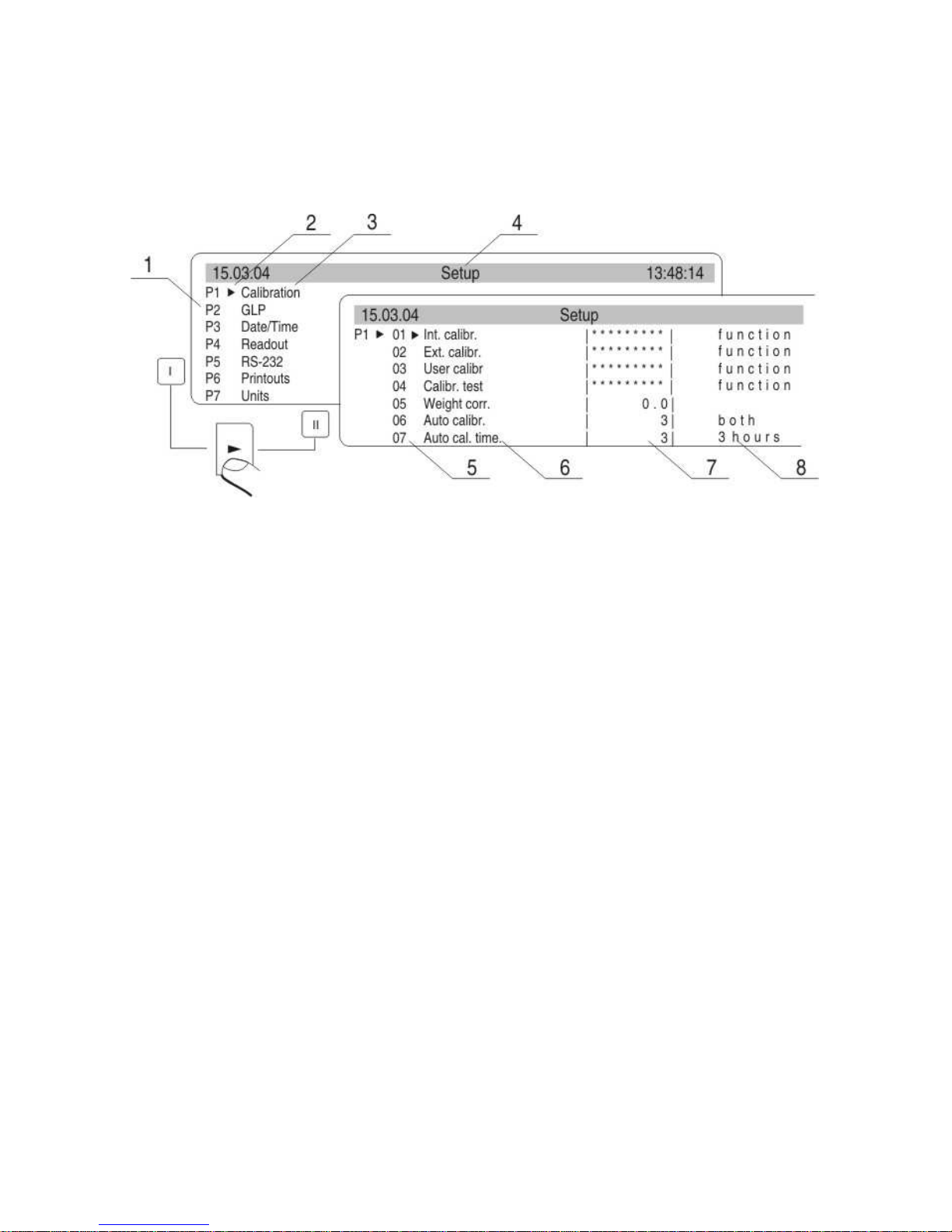
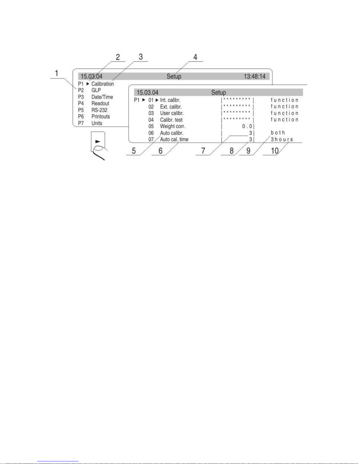
Menu – graphic version
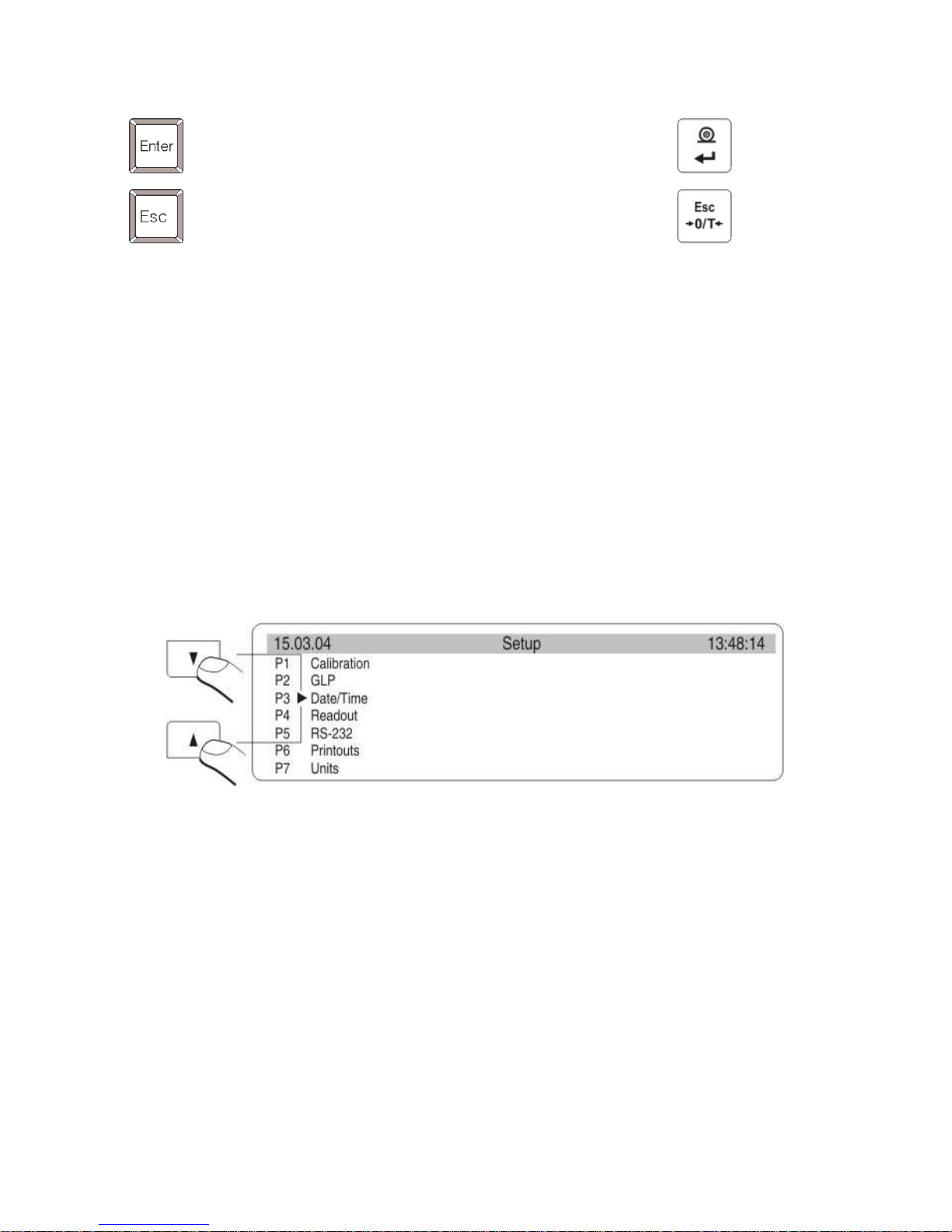
Press the SETUP key to display main menu of the balance (display I).
Select the submenu whose contents is displayed after pressing the RIGHT
ARROW key (display II).
Draw 5. Menu
1 – main menu number
2 – indication of the function selection
3 – function name
4 – currently used function
5 – submenu number
6 – submenu name
7 – attribute of the menu
8 – value of the attribute
5.1. Move in user menu
User moves in the menu by
- the balance keyboard
- PS keyboard,
- Communicates from computer to the balance
Page 14
- 14 -
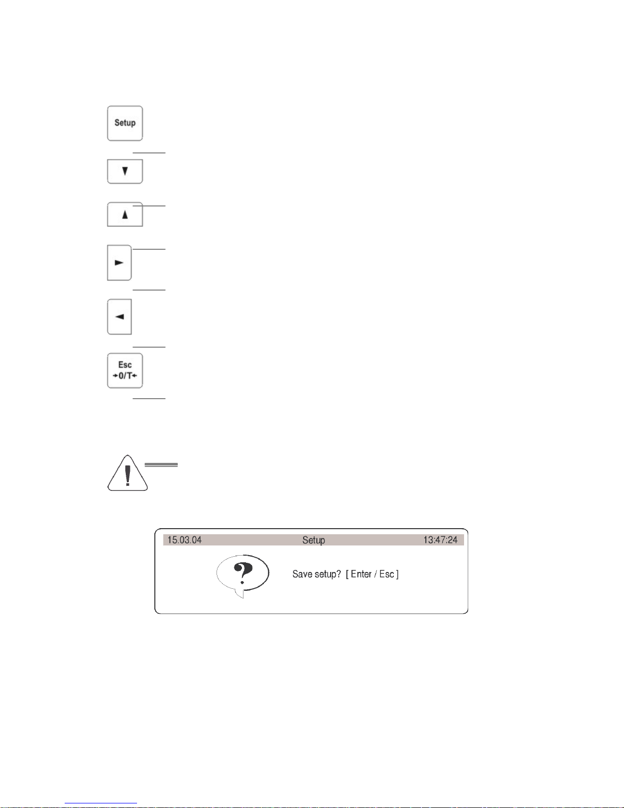
5.1.1. The balance keyboard
enter main menu
move down in the menu
move up in the menu
selects submenu which is activated. Submenu contents is
presented on the display
move one level up to main menu
Resignation parameter changing
5.1.2. Return to weighing function
Introduced changes are recorded after return to weighing
mode and confirm changes. Press the ESC key many times.
If following question appears on the display press: ENTER –
confirm or ESC – cancel
Draw 6. Return to weighing
Page 15
- 15 -
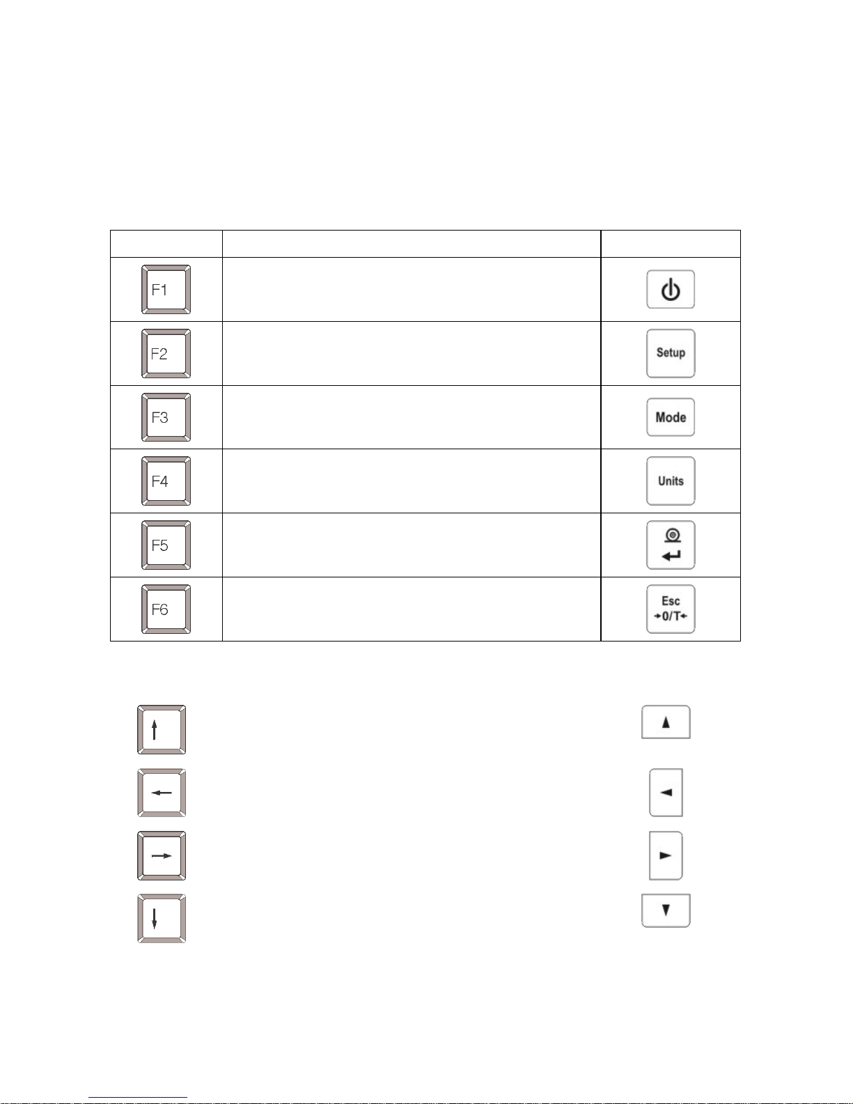
5.1.3. PS computer keyboard
Each key on the balance keyboard has its equvivalent on the PS keyboard:
- for functions
Description keyboard
Switch on/off the balance display
Move to the balance menu
Selects work mode
Selects measure unit
PRINT
TARE
- for direction keys
Move up
Move to level up
Sets selected parameter
Move down
Page 16
- 16 -
- for ENTER / PRINT keys and ESC
Confirm changes
Cancel and leave function without changes
5.1.4. By means of virtual keyboard through RS 232
Most of the functions are done by the balance desk or PS keyboard. They
are aslo done by sending orders computer – balance.
This commands enables to move in the balance manu and control the
balance work. The list of the commands is at the end of the manual.
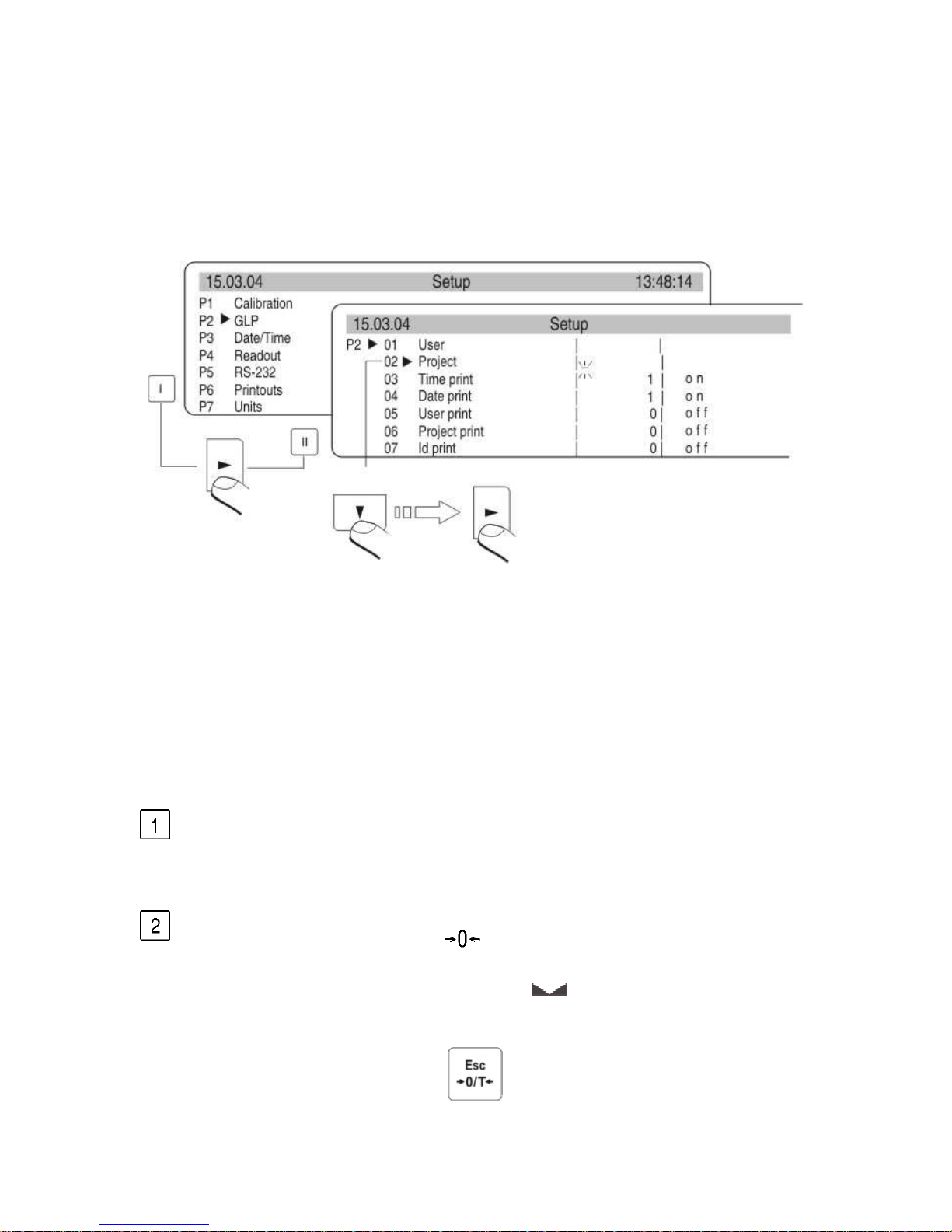
5.2. User menu
The menu is presented in p. 5. Press the F key in weighing level. Main
menu is presented on the display. Select the submenu which is
modificated.
Draw 7. Main menu – submenu selection
If the menu is modificated press the RIGHT ARROW key. Selected menu
appears on the display. Select what will be changed in this submenu
(activate). Select through keys presented on the Draw above. Press the
RIGHT ARROW key.
Page 17
- 17 -
Reaction of the balance:
- Activity of the balance (eg. the balance calibration) is done for
submenu described as Function
- Attribute activation for submenu which is indicated (digit flashing
means the value can be changed and some signs can be written)
Draw 8. Tthe balance submenu
6. WEIGHING
Following conditions must be fulfilled to get reliable results:
- Stable temperature
- Stable ground
- Proper parameters for external conditions
Before measurements or for essential changes of the external
conditions (if the temperature changes more than 1°C/h) calibrate the
balance in accordance with p. 7.1.
Before measurements load the pan and check if the balance show
„precise zero” – displayed in down left corner of the display
(only if the parameter P4 06 Autozero has the value 1: yes) and
check if the measurement is stable –
is displayed in right up
corner of the display. If the balance does not show zero press the key
Page 18

- 18 -
If the conditions are unfavourable (no stable result) lines appear on
the display. After settled time the balance returns to weighing mode
without set up to zero. In this case wait untill the conditions stabilize
and press Esc again
By the Units key select measure unit. Put the load on the pan and
after stabilization read out the result. If measure unit user wants to
use is not displayed during pressing the Units key check if it has
access attribute.
The indication can be set to zero many times. Sum of loads noted in
the balance memory cannot be higher than max capacity.
Betwenn following measurements do not unpluged the balance.
The balance should be switched off by the ON/OFF key. After
pressing the key again the balance is ready to work without warm
stabilization.
6.1. Log-in function
The operator has own access code to internal menu. The password system
is d
efined by administrator. Password can contain max 6 digits.
The balance program enables to declare:
• One administrator who is authorised to use all sets and
programme functions, change the passwords – own and user
• One user who is authorised to sets and the balance functions
determined by administrator
Setting password and access authorization
• After set the password and access parameters (parameter P9 13
Password protection) write the password for administrator
• If the admistrator password is different from “0” the program wants
administrator password during enter for the parameter
P9 13 Password protection.
• Every enter this parameter the software demands administrator
pass
word, after writting correct password it is possible to set the
parameter P9 13 Password protection
• Dependly on setting the password is shown as digits or stars (start
valu
e each digit = 0)
Page 19

- 19 -
According to p. 5.1.1 of the manual enter the menu P9 Globals
Draw 9. Password – activation the function
- Draw 9-1. Menu password protection
- Administrator
line to write administrator who has access to all set up
- User
line to write user password. User who has access to setting with NO
attribute (are not protected by password)
- Start up
If it is settled on YES during start the balance up user must write
access password (administrator or user)
- Functions
If it is settled on NO (not protected by password) user can use
implemented functions in the balance.
- Set up
If it is set up on NO (not protected by password) user can change
setting in the balance
- Only Kal+GLP
If it is set up on YES user can perform the calibration and calibration
report
- Stars
If it is settled on YES during start the balance up password is hidden
Page 20
- 20 -
under starts
Administrator password
Write the password for administrator (max 6 digits) and user. Each
admistrator has access to all functions in the balance. User has access
to balance possibilities in accordance with above description. Please,
remember the password. If you set YES for „Start up” function the
password must be writen after switch the balance on.
If the password is not correct using the balance is not possible.
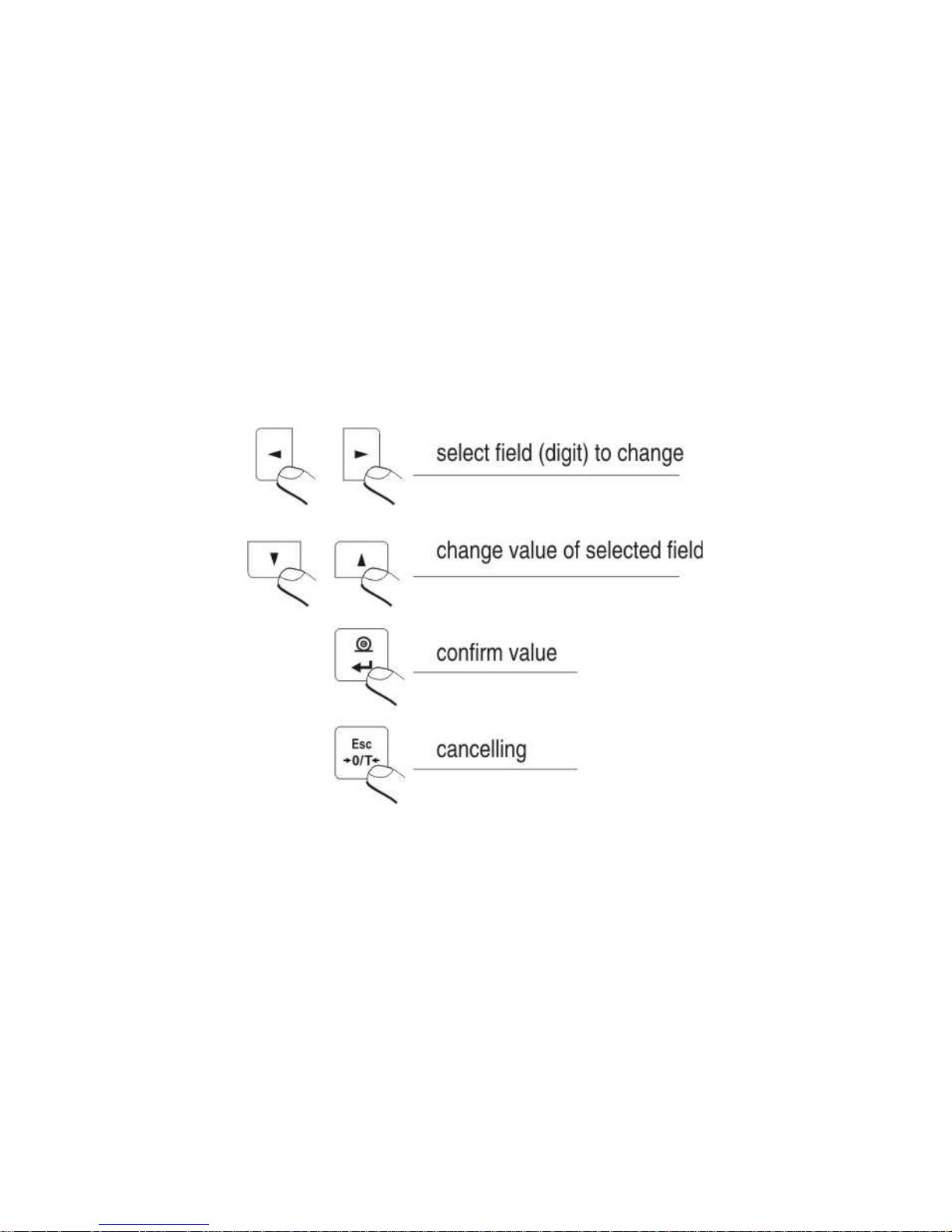
To write the password in use keys described on the drawing 2. or PS/2
keyboard (it can be connected to the balance port).
Set up the attributes for other options dependly on authorizations for
user.
Draw 10. The keys – introducing the values in the menu
Page 21
- 21 -
7. BALANCE CALIBRATION
To ensure high precision of weighing corrective factor in relation to
standard mass must be noted in the balance memory periodicaly – it is the
balance calibration.
Calibration should be performed when:
- The weighing is started,
- Long breaks are between following measure series
- Temperature inside the balance changes more than: 0,8°C
Kind of calibration:
- Internal automatic calibration
* started if temperature changes, started if the time changes
- Manual internal calibration
* started by the balance keyboard
- Calibration made with external weight
* with declared mass which cannot be modificated
* with any mass which should be given before the calibration
process
In verified balances only automatic internal calibration and manual internal
calibration is accessible.
Perform the calibration when there is no load on the pan!
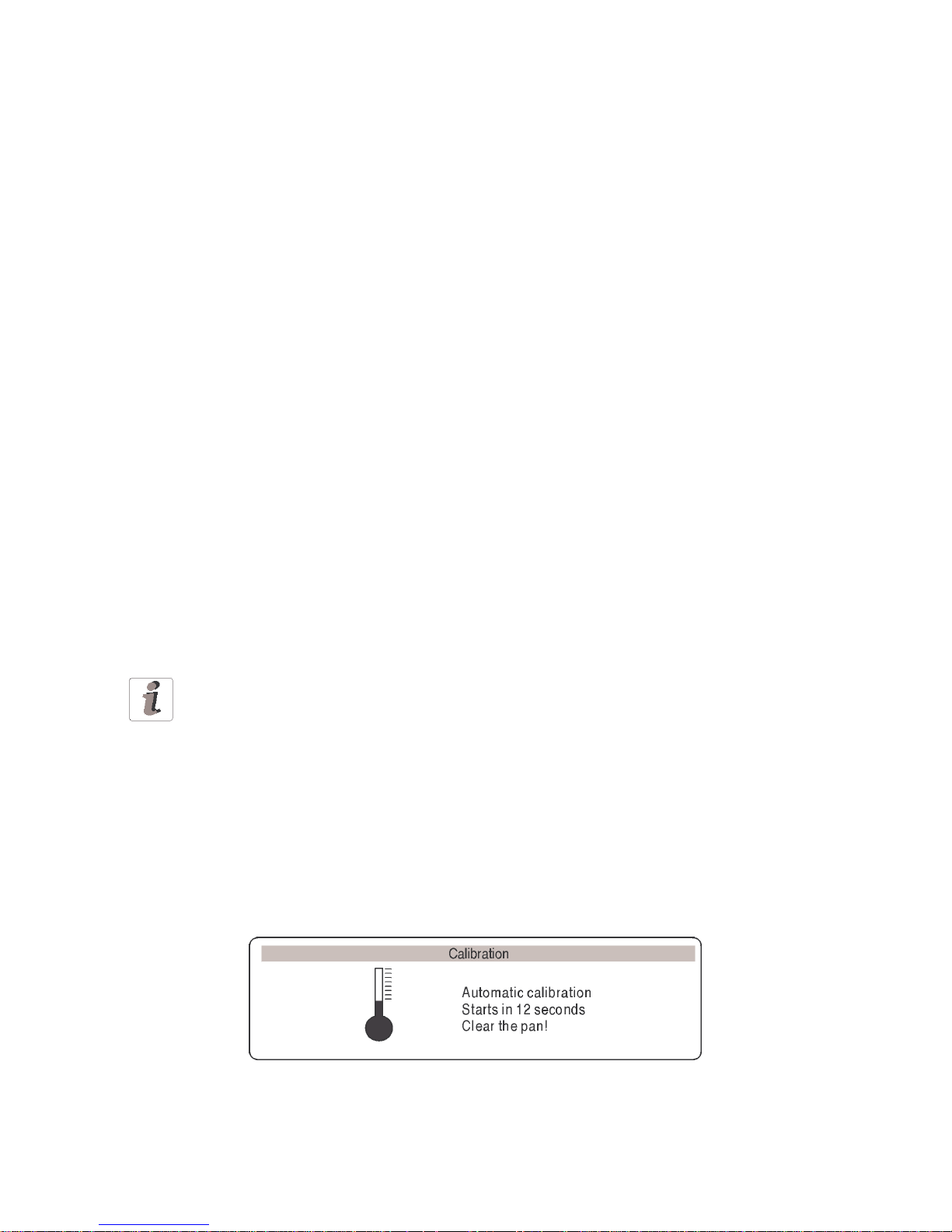
7.1. Automatic balance calibration
It is performed when:
- Period of time passes from last calibration
- temperature changes for settled value by manufacturer
* for balances is 0,8°C,
Following information appears on the display:
Draw 11. automatic calibration – display
Time delay in starting the calibration up enables user to yese load off the
pan untill the measurements are performed. If the T/O key is pressed the
Page 22
- 22 -
calibration process is stopped.
Set up automatic calibartion
Draw 12. Set up automatic balance calibration
1 –
main menu number
2 – function selection factor
3 – function name
4 – name of actual activity
5 – selects factor to autocalibration (time / temp.)
6 – declaring autocalibration time
7 – value of factors for autocalibration
8 – value of time for autocalibration
if the values for factor and autocalibration time also descriptions for tchem
changes (on the drawing field No 9. and No 10.)
01 Internal calibration
Start internal calibration process, the process is automaticaly without
operator interference, if there is load on the pan the display shows
order to remove the load
02 External calibration
calibration performed by external mass, its value is recorded in factory
menu, function inadmissible in verified balances
03 User calibration
calibration performed with any mass which must be introduced before
the calibration, function inadmissible in verified balances
04 Calibration test
comparison internal calibration mass with its value recorded in the
balance memory
Page 23
- 23 -
05 Weight code
correct value of internal calibration mass, function inadmissible in
verified balances
06 Automatic calibration
determine factor which decides about start automatic internal calibration
0 non – non of the factors causes start of the calibration
1 time – calibration in relation to time determined in p. 07
2 temperature – calibration in relation to changes of surroundign
temperature
3 both – calibration in relation to changes of time and temperature
07 Automatic calibration time
Determination of time automatic calibration starts up
Return to weighing
The changes are recorded when the balance returns to
weighing mode with the recording the changes. Press the
ESC many times. Following question appears on the display.
Select one of the options : ENTER – record / ESC – cancell
(see. Draw 9. Return to weighing p. 5.1.2. Return to weighing)
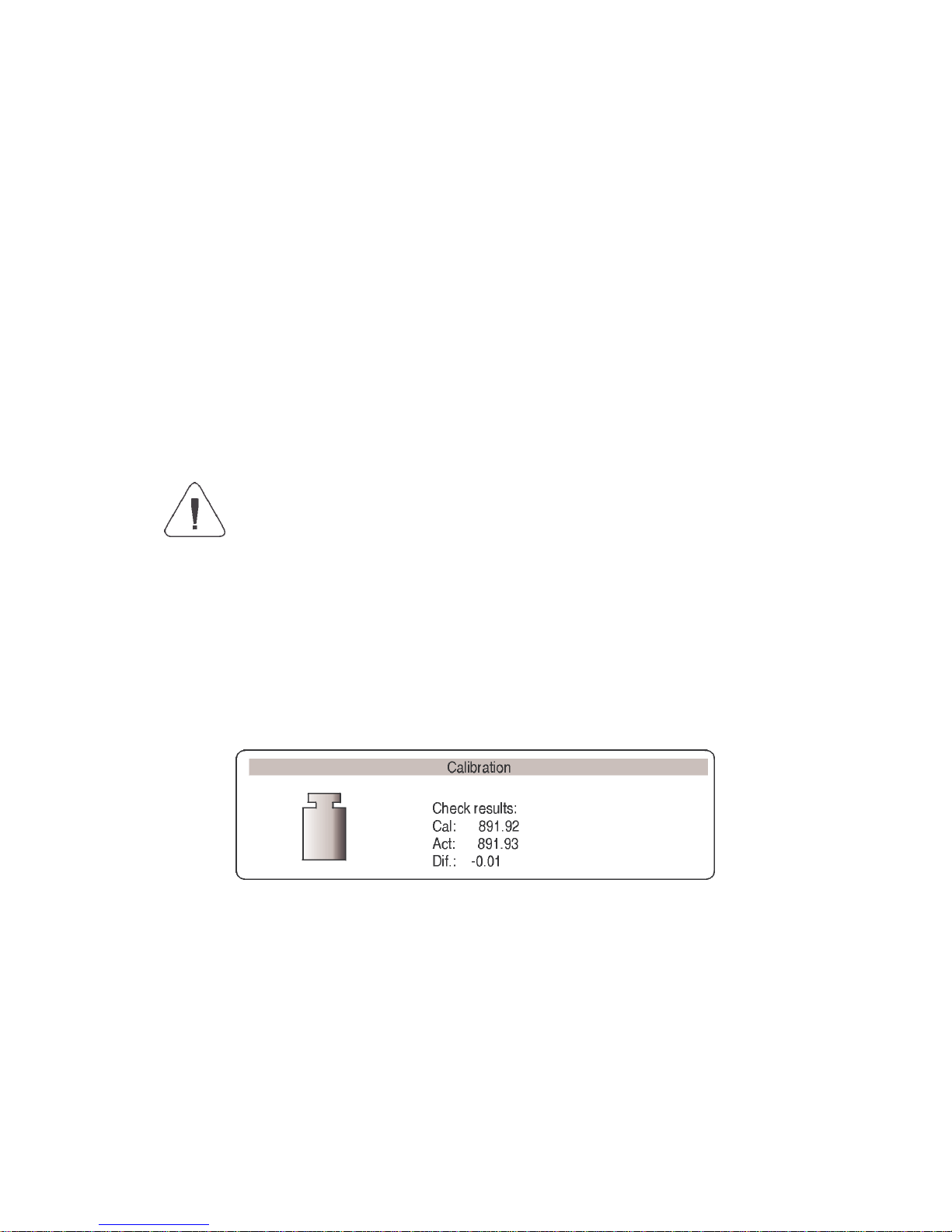
7.2. Calibration test
Internal calibration mass is compared to its value in the balance memory.
This preocess is automatic. Its result is shown on the display.
Draw 13. The calibration test
Cal. – value of internal calibration mass
Act. – result of weighing internal calibration mass
Dif – difference between two values
Page 24

- 24 -
Return to weighing
Changes are recorded only after return to weighing mode and
confirmation the changes. Press the ESC key many times.
Following question appears on the display. Select one of the
options: ENTER – confirmation / ESC – cancel.
(see. drawing. 9. Return to weighing. p.. 5.1.2. Return to
weighing)
7.3. Manual calibration
7.3.1. Internal calibration
1. Enter submenu P1 – Calibration.
2. Select the function 01 Internal calibration.
3. Press the RIGHT ARROW key.
4. The balance performs the calibration automatically. During this
calibration do not load the pan.
5. After this process the balance records results of the calibartion in
the memory and returns to weighing mode.
- Pressing the ESC key stops the calibration process
- If during the calibration load is on the pan display show order
about error. The calibration process is stopped.
After take load off the calibration process is finished.
If the function DRH is active user cannot stop the internal
calibration process.
7.3.2. External calibration
The external calibration should be performed with external mass class:
- E2 – for balances ASB/X
List
of weights for separate balances is included in technical specification in
the final part of the manual.
1. Move to submenu P1 – Calibration.
2. Select the function 02 external calibration
3. Press the RIGHT ARROW key.
4. Order to yese the load off the pan appears on the display (no load
on the pan). After yesing load off the pan press the ENTER key.
Page 25

- 25 -
5. The balance determines mass of empty pan
6. Put load and press the ENTER
7. After the calibration the balance returns to submenu P1 Calibration
8. Return to weighing – as in the point 5.1.2.
If the function DRH is active user cannot perform the external
calibration process. Function DRH is active in verified balances.
7.3.3. Calibration performed by user
Calibration performed by user with aby external weight class:
• E2 – for balances ASB/X
- Enter menu group P1 Calibration. Select the parameter
03 user calibration
- Press the RIGHT ARROW key. The balance displays order to note
calibration mass. The first digit flashes and it can be changed.
Draw 14. User calibration – declaring value of weight
- Record new external mass by functional keys (in accordance with p.
5.1.1 of the manual)
- Confirm the mass. The balance starts calibration and shows orders on
the display.
- The balance determines mass of empty pan and shows order to put
this mass
- After put the weight on the pan confirm by the Enter.
- After this procedure balance returns to menu to group P1 Calibration.
- In accordance with previous point start weighing mode.
It is recomended to select external calibration mass as its mass
would be about ¾ of max balance capacity.
If the DRH function is active user cannot perform the external
calibration process.
Page 26

- 26 -
7.3.4. Calibration report printout
After calibration user can reveice the calibration report. The report can be
printed on connected printer and sent to computer or recorded in file.
P1 08 Report printout: 1: yes – report is printed
P1 08 Report printout: 0: no – report is not printed
If the parameter has the value 1 the report is genrated and sent
automaticaly.
Draw 15. Submenu calibration
A content of report depends on setting in submenu GLP. All options with
YES attribute are printed.
Draw 16. Submenu GLP - setting
Apar
t from information settled in menu group the report contains:
calibration mass remembered by balance after last calibration (description
Old:), calibration mass determined during actual calibration (description:
Calibration) and deviation of the calibration (description Deviation:) –
difference between these two masses.
Page 27

- 27 -
Draw 17. Example of balance calibration report
8. SETTING PRINTOUTS FOR GLP PROCEDURES
P2 GLP is group of the parameters which declares factors on the
calibration printout. For fields:
- user (max 8 alphanumerical signs)
- design (max 8 alphanumerical signs)
introduce names by the balance keyboard or the PS/2 keyboard. For the
rest select:
- 1 no (do not print during report)
- 0 yes (print during report)
Main view of the GLP submenu is presented on drawing 19, page 24. If you
use
the PS/2 keyboard see what dipendences are between the balance
keyboard and PS/2 keyboard (p. 5.1.2)
9. SETTING TIME AND DATE
The balance has real time clock whose parameters can be modificated.
Enter the menu group P3 Date/Time as it is show below:
Draw 18. Submenu Date / Time
Page 28

- 28 -
01 Date form
There are two possibilities:
- 1 format date Month/Day/Year
- 0 format date Day/Month/Year
After selection proper value confirm by the ENTER key.
02 Time form
There are two possibilities:
- 1 time form 12 h
- 0 time form 24 h
After selection press the ENTER to confirm.
12 h form is distinguished by the letters PM or AM on the printouts.
03 Time
Enter setting the parameter 03 Time by the RIGHT ARROW key in
accordance with below scheme.
Draw 19. Submenu / Time – setting time
Replace the marker next to the value which will be changed (Hour, Minute,
Second). Confirm with the RIGHT ARROW key. Change the numerical
values with Mode and Units keys.
Page 29

- 29 -
Draw 20. Submenu Date / Time – setting time – steering keys
Confirm settled value (last change digit stops flashing)
Repeat above activities for following values. After setting new values for
time press the ENTER key. The balance returns to submenu P3 Date/Time
and displayed time changes.
After setting time return to weighing mode in accordance to p. 5.1.1 of the
manual.
04 Date
Set the parameter 04 Date with the RIGHT ARROW key. In accordance
with previous description (03 Time) set actual date. After setting date return
to weighing mode as it is presented in p. 5.1.2 of the manual.
Draw 21. Submenu Date / Time – setting date
Page 30

- 30 -
05 Display time
for the value 1 – YES on top graph time is displayed, for the value 0 – NO,
time is not displayed.
05 Display date
For the value 1 – YES date is displayed on top graph, for the value 0 – NO,
date is not displayed.
Return to weighing
(see Draw. 9. - 5.1.2. – Return to weighing)
10. SETTING THE PARAMETERS
User can adjust the balance to existing conditions (filter) and own needs
(autozero, displaying last digit) by means of parameters in group <P4
Readout>.
Draw 22. Submenu Readout – internal setting
10.1. Setting filter
Dependly on conditions set the filter. If the conditions are conductive set
the filter as very fast (value of the parameter 01 Filter 1) and if the
conditions are bad (vibrations, draught) set the filter as slowly or very
slowly (value of the parameter 01 Filtr at 4 or 5). Efficience of filter is
different for range of weighing. The filter works slowler during getting to
weighed mass. It works faster when mass is the settled filer range
(parameter filter range accessed only from service menu – user does not
have acess).
Page 31

- 31 -
10.2. Value release
Select and set way for stability result of weighing: fast, fast +reliable or
reliable.
10.3. Set the display refreshing time
This parameter determines period of time which the display refreshes in.
Information on the display is compared to information which is sent by the
balance processor about load on the pan.
For higher values of the refreshing parameter indirect not stable mass
indications are not presented on the display during puttin on and yesing off
the load. For low values all changes in mass during weighing are visible – it
enables to dosage liquids and solids. The refreshing time is settled in
seconds.
10.4. Set autozero working
To ensure precise indications programmable function „AUTOZERO” is in
the balance. This function controls automaticaly and corrects zero
indication of the balance.
If the function is active following results in declared periods of time are
compared eg. each 1s. If these results differs at less value than declared
range AUTOZERA eg. 1 interval the balance sets to zero automaticaly and
and appears on the display.
If the AUTOZERO function is active each measurement starts at precise
zero every time. In special cases this function disturbes in the
measurements eg. when the load is put on the pan very slowly (pouring
substance). In this case correcting system of zero indication can correct
also indication of real load mass. AUTOZERA is switched on anr off in the
parameter P4 03 in accordance with p. 5.1.1 of the manual.
15.5. Displaying last digit
10.5. Last digit
To ensure komfort of work with the balance user determines (dependly on
needs) if last digit should be displayed and when. One of the following
values can be selected:
- 0 never
- 1 always
- 2 when stab
Page 32

- 32 -
10.6. Negative
This function is designed for changes of displaying.
11. FUNCTIONS IN USING RS 232 PORT
User can set the parameters necessary for correct comunication balance
with computer or printer.
Draw 23. Submenu RS 232 - setting
Parameter No and name Parameter No and name
01 Baud rate: 0 : 2400;
1 : 4800;
2 : 9600;
3 : 19200
07 Interval
Interval it is defined how often balance sends
indications through RS 232 port. It is counted
on base on form for the parameter x 0.1 s =
time yestu-interval). Value from 1 to 9999 can
be written.
02 Parity: 0 : no;
1 : see;
2 : dont see
08 Min. mass
03 Date bits: 1 : 7 bits;
2 : 8 bits
09 Print on stab 0 : no;
1 : yes
04 Stop bits 1 : 1 bit;
2 : 2 bits
10 Printer type: Epson /Standard (Kafka)
05 Handsake
:
0 : no;
1 : RTS/CTS;
2 : XON/XOFF
11
Cut paper
: Disabled / enabled
(function for printer EPSON TM-U220B or A
only)
Page 33

- 33 -
06 Auto print 0 : none;
1 : constance; 2 : with breakes;
3 : for stable.
After setting correct values return to weighing mode as it is described in p.
5.1.2 of the manual. For value 1 : computer parameter 09 Printout to, for
printouts the last digit of indication is omited.
12. PRINTOUTS
This function is used to make not standard printouts and select type of
printout. Precise description for printouts is described in p.17.
13. ACCESS TO MASS UNITS
In this group of parameters user declares mass units which are accessible
for operator directly under the key Units.
All units which value of the parameters is set up at 1: yes are accessible
from the level of switching between units.
For units described as 09 Taele Hk., 10 Taele S., 11 Taele T . there are
following dependences:
• If all of them have attribute 1: yes the balance show only first of
them 09 Taele Hk
If the measurement is done in units 11 Taele T set the a
ttribute 0 : no for two
previous
Enter group of the parameters P7 Units according to p. 5.2.7.
Draw 24. Measure units - setting
After set proper values of the parameters return to weighing mode in
accordance to p 5.1.2 of the manual.
Page 34

- 34 -
14. SETTING ACCESSIBILITY OF THE WORK MODES
In this group of parameters user declares work modes which are accessible
for operator after pressing Mode key.
Draw 25. The balance functions - setting
All work modes values of the parameters are 1: yes are accessible from the
level of switching between work modes. The changes of the parameters
can be done according to p. 5.1.1 of the manual.
15. OTHER PARAMETERS
User can set parameters have influence on work with balance in group of
the paraemeters P9 Others eg. beep signals etc. Enter submenu group P9
Others the same as in pakt. 14.
01 ID Setting
it includes 6 digits 6 codes which can be used during printouts for
product specification, operator, batch etc.
02 Aut. Printout ID
for the option YES all digit codes are printed, for option NO the codes
are not printed.
03 Signal
beep signal for pressing keys
Page 35

- 35 -
04 Language
selection of languages
05 Backlight
switch on/off the backlight
06 Contrast
changes contrast – after entering this function a window appears, by
means of keys on the balance contrast on the display can be changed
07 Screen server
if the screen server is switched on displayed values disappear after
settled time and if displayed value of the measurement does not
change.
08 Temperature
it is information about temperature which is registered by temperature
sensor in the balance. Return to the menu – press the ESC key
09 The balance number
it is only information about factory number of the balance
10 The number of the program
it is information about program number of the balance
11 Printout of the parameters
if the function is active the balance parameters in user menu are
printed. User gives numbers of the parameters which should be
printed.
Draw 26. Submenu Others - printing setting
Page 36

- 36 -
After confirmation parameters are printed through RS 232 port, actualy sent
settled user parameters in the balance
12 The parameter reception
If the functions are activated all parameters of the balance are received
through RS 232. After reception the balance informs user how many
parameters are accepted, how many are changed, how many were
declared incorrectly and how many were not accepted by the software.
Printing and reception of the parameters is very easy and fast
procedure of introducing new setting.
After printing actual parameters to file in the computer user changes
the parameters very fastly and without any problems. User sends new
corrected setting to the balance software. After these changes the
balance accepts new set up. User must know all parameters and
computer operation very well.
13 Password protection
this submenu contains options about accee password for administrator
and user (see 6.1.)
16. USING WORK MODES
16.1.
Countign pieces of the same mass
It can be done after write singular piece mass:
- Write singular piece mass
- Determine singular piece mass on base of standard quantity
- Element selection from date base
Page 37

- 37 -
16.1.1. Counting pieces after writing piece mass
Start function of counting pieces (drawing No 33).
Draw 27. Counting pieces – main menu
Set standard mass and press the ENTER or select 07 Start and press the
RIGHT ARROW. Functions to count details are activated.
Draw 28. Counting pieces – display view
APW – singular piece mass [g]
WGH – all pieces mass on the pan
pcs – mark for counting pieces
Return to weighing
- Press the MODE and display shows list of all functions
- Select MO Weighing, Press the RIGHT ARROW, display show stage
of weighing
Page 38

- 38 -
16.1.2. Counting through determine singular element mass
from the standard batch
Start the procedure of counting pieces in accordance with p. 16.1.1, it does
not matter which mass in the field 01. Select 07 Start and press the key
RIGHT ARROW. In the counting pieces function press the key Units.
Dialog window appears on the display. Select the batch quantity (fiels 01 –
04) or write it in 05 – Standard.
Draw 29. Countimg pieces with using standard batch
Then press the RIGHT ARROW key and follow orders presented on the
display.
Draw 30. display with AKD function
1- single piece mass
2 - all elements mass
3 - AKD (automatic correction of preciseness) function
Page 39

- 39 -
Display shows quantity of pieces which are on the pan (10 pieces). If less
than counted actualy quantity is added mass of singular piece is corrected.
In this case APW = 5.2282 to 5.1837. From this moment following pieces
are counted in relation to singular mass.
This way mass of singular piece can be determined on base of batch
standard.
The are four conditions of AKD (Automatic Correction of Preciseness)
in the balance software
1. quantity of pieces (after adding) must be higher than it was
previously
2. quantity of pieces (after adding) must be less than twice quantity
which was on the display before adding
3. actual quantity must be in tolerance ± 0,3 of the total value,
4. the result must be stable.
If user decides that batch quantity is enough singular piece mass must be
introduced into the balanc memory after pressing the key RIGHT ARROW.
Draw 31. Automatic Correction of Preciseness – record in date base
Sele
ct the field and write names of weighed elements. Press the Enter
(record name) and Enter (record value). Next to name singular piece mass
should be introduced. It can be remembered using 02 Recall sample
Page 40

- 40 -
16.1.3. Select piece from date base
Active function of counting pieces as it is shown on below scheme.
Draw 32. Select piece from date base
Select piece form date base. Start counting pieces.
16.2. Checkweighing
The sample is weighed precisely when the limits of weighing are settled.
The process is shown (side graphs) and controled.
The function activation:
Draw 33. Checkweighing – the function activation
Display
Page 41

- 41 -
Draw 34. Checkweighing – display view
1 – result
2 – bargrafy
3 – function name
4 – difference between masyw of weighed load and middle of tolerance
field
(HI/LO)
5 – value of low (LO) and (HI) high limit
6 – graphs which presents weighign range
Rememeber to set the parameter
02 High limit firstly. The balance program checks if the values are
correct and if they are in measure range.
If settled values of the parameters are incorrect the balance shows
command about error and returns to setting parameters without changes.
Page 42

- 42 -
16.3. Filling
During dosage (pouring) load mass is filled up till the settled mass is
reached. Before the procedure set the standard mass which is upper stage
of the dosage.
Activation of the function
Draw 35. Dosage – activation of the function
Display
Draw 36. Dosage – display
1 – mass which should be added
2 – graphs
3 – function name
4 – TR reference value mass which is declared
(see drawing. 39. M3 01 Reference mass)
Page 43

- 43 -
5 – WGH mass on the pan
16.4. Percents
This function compares load mass to standard mass which value should be
given. The result of this operation is displayed in percentages.
Following functions: dosage, weighing, statistics can cooperate with
deviation function.
Activation of the function
Draw 37. Percents – activation of the fucntion
Display
Draw 38. Percents – display
1 –
percentage value, proportion of the mass on the pan and standard
mass
2 – function name
3 – REF masa odnosienia (see drawing 40 – M4 01)
4 – WGH mass on the pan
Page 44

- 44 -
Cooperation of the deviations with other functions
During activation of the function set option YES for parameters M4 03, 04,
05. Select field START and start work.
- after setting function Dosage YES give up and down stage as %
values
- after setting function Dosage YES give the mass value in %
- after selecting Statistics select field Cancel and cancel previous
statistics and change the attribute NO into attribute YES. Confirm
this option and press the key Enter.
Draw 39. Percents – cooperation with ther functions
1 – percentage value relation of the load on the pan to reference mass
2 – stable measurement sign
3 – function name
4 – REF reference mass
5 – WGH mass on the pan
6 – graph which presents weighign range where the weighing range is
7 – statistics (N=0 – no measurements)
8 – active function dosage (load mass between 90 – 110%)
Page 45

- 45 -
After measurements eg. 10 (quantity of measurements N=10) user can
see results of statistics of made measurements.
− Enter work mode
− Select the parameter 05 Statistics
− Pressing the F key and enter the parameter 05 Statistics
− Select the parameter 02 Results
− Enter function of showing statistics results
− After pressing the ENTER statistics result can be printed
− Return to statistics submenu and higher levels – key ESC
Draw 40. Percents – cooperation with other functions - Statistics
Page 46

- 46 -
16.5. Weighing animals
Function activation
Draw 41. Weighign animals – view of the display
External setting
- FILTR (Decides how fast final stable result is received, the faster
filter the shorter time of measurement)
- STAGE (Value in actual scale intervals is value the result must be
below The result of weighing must be smaller than value of actual
scale intervals in order to do following automatic measurement)
- AUTO START (Automatic start up following measurements)
- STATISTICS (Statistics counting for particular subjects)
- START (Start measurements up)
Page 47

- 47 -
16.6. Density of solids and liquids
In additional equipment of analytical balances there are Specific Gravity
Measurement Kit.
Draw 42. Specific Gravity Measurement Kit
Components of the kit:
1 Beaker stand 7 String
2 Pan stand 8 Float hook
3 Float 9 Top pan
4 Beaker 10 String
5 Thermometer
clamp
11 Bottom pan
6 Termometer 12 Attachments
16.6.1. Density of liquids
Basic component during measure solids of liquids is glass float. It has
precise determined capacity which is stamped on the float hook. Write
password to balance memory before the measurements.
During the measurement of liquid density mass of glass float in the air is
compared to its mass in the liquid.
The result is presented on the display automaticaly after its counting by the
balance program. The result can be sent through RS 232 to printer or
computer after pressing PRINT key.
Page 48

- 48 -
16.6.2. Density of solids
Density of solids can be determined in one of 3 different liquids:
− WATER (destiled water),
− ALCOHOL (spirit 100% +/- 0.1% at 20 °C),
− OTHER (other liquid with known density)
Measurement of density of solids is based on comparison sample mass in
air (weighed on top pan) to the same sample mass in the liquid (on bottom
pan).
The programme counts density of sample and displays it on the display.
The result can be sent through RS 232 to printer or computer after setting
the key PRINT.
Precise description of measurements performance and setting is
the manual of Specific Gravity Measurement Kit.
16.7. Formulation
This function is used to make mixtures under recipes. This function is
recomended to use in drug-stores. The program is equiped with calculate
memory. The balance remembers singular component mass and sum of
weighed components.
Following information are presented on the display in this work mode:
1. load mass on the pan
2. actual weighed component name (max 10 signs)
3. mass which should be measured for actual weighed component
„WGH”
4. quantity of components which is weighed in the mixture „IC”
5. components mass already weighed „SUM”
Page 49

- 49 -
The function activation
Draw 43. Recipes – internal setting
parameter 01 Hints
after set the parameter at YES the balance displays names and singular
components mass recorded in the parameter 04 Recipe on the graphic
display
parameter 02 Automatic printout
after set the parameter at YES the balance sends value on printer or
computer through RS port after confirmation mas sof each component
parameter 03 Quantity of components
user determines quantity of components the mixture should include (max
20 signs)
parameter 04 Recipe
after set this parameter following submenu is displayed. In this submenu
user can wirte names (not more than 10 signs) and set (standard mass) of
each component in the mixture
parameter 05 Recipe printout
This function prints composition of the mixture on connected printer. There
are names and setting of particular component and total contents of the
mixture.
parameter 06 Statistics
Page 50

- 50 -
parameter 06 01 Statistics
switch on (YES) or switch off (NO) statistic couting
Attention:
Statistics counting refers only to total mass of prepared mixtures (singular
components mass are not counted).
parameter 07 Start
enter work modes Recipes
Information on the graphic display for recipes
Draw 44. Recipes – functions
1 – mass which is actualy on the pan.
2 – stable measurement sing
3 – function name
4 – settled mass of the weighed component in the parameter
04 Recipe
5 – Sum of weighed components of the mixture which are in calculate
memory of the balance
6 – quantity of weighed components in the recipe
7 – name of weighed component
8 – sige graphs. Information how much left to gain settled component
is presented on these graphs.
Draw 45. graphs – automatical scale
Page 51

- 51 -
Procedure of preparing mixtures – according to recorded components
and their mass in the balance memory
Write names and components mass in the parameter 04 Recipe.
Remember about the dependences:
− there cannot be more than 10 signs
− confirm each name by the ENTER key and write mass which will
be in the mixture
Draw 46. Declared recipes
− total mass of the mixture together with the container cannot be
bigger than max capacity of the balance
− there cannot be more than 20 components in the mixture
− Write quantity of components in the parameter 03 Quantity of
components
− Quantity of components cannot be higher than 20 pcs
− The program records mixture contents in order they were
introduced in the parameter 04 Recipes. If user writes 10
components in the parameter 04 Recipes and set 8 for quantity of
components the program finishes preparation of the mixture after
weighing 8 components.
− The balance programe creates mixture in order of recorded
components in the parameter 04 Recipes and starts from the
component 1 and finishes at settled component in the parameter
Page 52

- 52 -
03 Quantity of components
− If the documentation is printed set the parameter 02 Automatic
printout at 1 : YES. After confirmation of each component (key
UNITS) their mass are printed on connected printer or computer.
• Set the parameter 01 Prompts at 1 : YES
• Enter function Recipes by pressing the ENTER key
• Tare container mass to the balance memory
• Weight first component (mass in the WGH)
• Press the UNITS key. Mass of component 1 is recorded in the
balance memory. The information on the display changes:
component 2, mass WGH, IC=1, SUM=. . . .
• Information on the display is settle do zero.
• Repeat it for all components
• After weighing last component and write its mass to the balance
memory (the UNITS key) total mass of mixture and prompts to
following steps are displayed.
Procedure of making mixtures without recording components and
their mass date in the balance memory
If documentation of preparong mixture is printed set the parameter 02
Printout at 1 : YES.
If mass of each component is confirmed each mass with their names is
printed on connected printer or computer.
• Set the parameter 01 Prompts at the value 0 : NO
• Enter function Recipes by pressing ENTER
• Tare container mass to the balance memory
• Pour component 1 to the container – in relation to information
about mixture
• Press the UNITS key. Mass of component 1 is recoded in the
balance memory. The information on the display changes: IC=1,
SUM=. . . The indication is set to zero. Press the key Units
• Repeat it for all components of the mixture
• After write last component press the →→→→0/T←←←←. Procedure of making
mixtures is finished. Sum of mixture is kept on the display.
Statistics counting
Statictics counting relate only to making mixtures (particular mass
components are not included in the counting).
If user performs statictic counting in this work mode:
1. enter the parameter 06 Statistics
Page 53

- 53 -
2. cancell previous results of statistic counting
3. set the parameter 06 01 Statistics at YES
4. enter work mode for preparing mixtures
5. perform measurement series
6. enter the parameter 06 Statistics again
7. enter the parameter 06 02 Results
8. to print results press the key PRINT
16.8. Statistics
Activation
Draw 47. Statistics – fucntion activation
Results of previous statistics should removed after function activation. It is
realized through option M8 01 Cancel.
All statistic date are actualized after write following measurement to the
balance memory. Following measurment is writen to series after load is put
on the pan, stabilization of the result (measure unit is displayed) and after
pressing ENTER.
Page 54

- 54 -
User decides what statistic date are presented on the graphic display
during measurements by setting their activity in the submenu of work mode
(values which are set for YES are active). Independly on setting (YES/ NO),
during final result the printout contains full statistics.
N : 5 (quantity of weights)
SUM : 161.121 g (all components total mass)
X : 32.224 g (average mass of weighed components)
MIN : 20.486 g (min mass)
MAX : 35.578 g (max mass)
D : 15.092 g (difference between Max- Min)
SDV : 6.581 g (standard deviation)
RDV : 20.4 % (variation factor)
Draw 48. Statistics – display for series of measurement
1. mass on the pan
2. measurement number in measurement series
3. sum of all weighed components in measurement series
4. average mass of weighed components in the series
5. mass of the lightest component in measurement series
6. mas sof the heaviest component in measurement series
7. difference between the lightest and the heaviest component in
measurement series
8. value of counted standard deviation
9. value of variation factor
10. measure unit [g]
11. work mode
Page 55

- 55 -
17. KINDS OF PRINTOUTS
17.1. Standard printout
The are 2 types of printouts. First of them is standard printout. It includes
result of weighing and all variables which have attibute YES in GLP
submenu. In User and Project fields names should be written.
Draw 49. Declaration of variables to printout – submenu GLP
Example of standard printout
Draw 50 Example of standard printout
(all option settled on YES – printed)
Page 56

- 56 -
Draw 51 Example of standard printout
Question mark before load mass means that the result is not stable.
17.2. Non-standard printout
Procedure of creating non-standard printouts:
− user can create own 4 printouts,
− give the number of the text which starts the printout eg. Printout 1
Start – 1 and text number which finishes the printout eg. Printout 1
Stop – 40. In this case texts from 1 to 40 are printed.
− And then write text in the lines 1 ÷ 40.
It is recomended to use PC keyboard what is simplier and faster
way.
− Non-standard printouts can overlap each other:
Printout 1 Start – 1
Printout 1 Stop – 40
Printout 2 Start – 20
Printout 2 Stop – 40
− Non-standard printout can be created by Edition of the
printout.
During
manual writting give all special signs as CRLF, tabulator etc. If function
Printout Edition is used all these values can be selected in form of ready elements.
They are transmitted from one side Line of selection to the other window Printout
Page 57

- 57 -
Draw 52. Menu pritnouts – the function activation
Non-standard printout can include:
− Variable dependly on work mode and other user necessities
(mass, date, Project No)
− Stable texts in user menu
− Non-standard printout can include not more than 640 signs
recorded as 80 texts 8 signs each (from the parameter Text 1 to
Text 80). User can design 4 non-standard printouts
17.2.1. Texts
Variables in all modes and with the same values
%% Printout of „%” singular sign
%N Actual net mass in basic unit
%d Actual date
%t Actual time
%i The balance number
%R The program number
%P The Project number
%U The user number
%F Actual function name – work mode
%C Date and time of last calibration
%K Kind of last calibration
%I Deviation of last calibration
%1 Code 1
Page 58

- 58 -
%2 Code 2
%3 Code 3
%4 Code 4
%5 Code 5
%6 Code 6
Variables dependent on used work mode
Variable Description Mod where the variable is active
%W 1 piece mass COUNTING PIECES
%H Top stage
%L Down Stage
WEIGHING
%Z Standard mass DOSAGE
%B Reference mass DEVIATIONS
%A Filter
%b Stage
WEIGHING ANIMALS
%i Liquid
%p P
rocedure
%c Temperature
%a Density of liquid
%v Float capacity
MEASUREMENT OF DENSITY
Statistic variables in all modes apart from basic weighing
%n The measurement number
%x Average value
%S Sum
%m Min value
%M Max value
%D Difference between max and min value
%s Standard deviation
%r Variation factor
Variable in all modes which value depends on the mode
%V – Mass in actual unit. Value connected to work mode eg.
counting pieces for mode Counting pieces or deviation from
standard mass in % for mode Deviation
Page 59

- 59 -
Special signs used to create special printouts
\\ Singular sign „\”
\c CRLF
\r CR
\n LF
\t Tabulator
\s skip to next „string”
\0 End of the printout
Each text (Text 1 ÷ 89 Text 80) can include max 8 signs (letters, digits,
special signs, spaces). To write long sentence create it using 8 sings texts.
User can use special signs to include variables dependly on own
necessities.
Example 1:
Max mass cannot be higher than 11.250 g!
If user write this sentence uses 640 signs grouped in adjacent lines of the
text. Set up following texts and write 8 signs in each of them untill the
sentence finishes.
Text
Parameter number
1 2 3 4 5 6 7 8
19 Text 10 M a s a m a k
20 Text 11 s y m a l n a
21 Text 12 n i e m o
e
22 Text 13 p r z e k r a c
23 Text 14 z a
1 1 . 2
24 Text 15 5 5 0 g !
Page 60

- 60 -
Example 2:
„MRC”
Date:
Time:
Load mass:
*****Signature:.........
***<actual work mode>***
Set following texts and write 8 signs in each of them untill it is finished.
Text Parameter number
1 2 3 4 5 6 7 8
25 Text 16 Z a k ł a d M
26 Text 17 e c h a n i k i
27 Text 18 P r e c y z y
28 Text 19 j n e j „ R A
29 Text 20 D W A G „ \ c D
30 Text 21 a t a : % d \ c
31 Text 22 G o d z i n a :
32 Text 23 % t \ r \ n M a
33 Text 24 s a ł a d u n
34 Text 25 k u : % N \ c \
35 Text 26 c * * * * * P o
36 Text 27 d p i s : . . .
37 Text 28 . . . . . . . \
38 Text 29 c * * * % F * *
39 Text 30 *
Page 61

- 61 -
− On the balance desk
Move up through digits, letters and sings o 1
Move down through digits, letters and sings o 1
Determine sign to change and move right (if the key is pressed
flashing sign is moved in right direction. If no sign is written this
keys makes space in the text)
Determine sign to change and move lef (after this key is pressed
flashing sign is cancelled)
Confirm the text
− On PS/2 keyboard
Press F2 to enter main menu. Press F3 to set parameters
indications next to group P6 Printouts and press F2 to enter menu
group and then select parameter. Press F2 to activate the
procedure of writing the text. By means of keyboard write the text
(max 8 signs) and confirm by Enter. Repeat this procedure for the
rest of the texts.
Description of the computer keyboard is in the p. 5.1.3
Page 62

- 62 -
17.2.2. Composing texts by Edition function
The function activation
Draw 53. Not standard printouts – printout edition
Draw 53-1. Not standard printouts – printout edition – select
Page 63

- 63 -
After activation of the function select printout number (1-4) and beginning of
writting the texts in (range from text 1 to text 80). Then select the option
Edition to edite (create) printout or cancell all (remove all printouts).
Draw 54. Edition of printouts – selection of the elements
To s
elect following fields use keys ARROWS TOP/UP. To print field press
the RIGHT ARROW key. After the edition press ENTER/PRINT. Display
shows question if printout should be done – press ENTER/PRINT again.
17.2.3. Select non-standard printouts
if STANDARD printout is selected – there will be only result and variables
declared in the GLP (see p. 17.1 Standard printout - drawing 52. Declaration of the
variables to printout – submenu GLP).
If non-standard printout is printed select kind of the printout (1-4) and give
the beginning and end of the printout.
Page 64

- 64 -
18. COOPERATION WITH PRINTER OR COMPUTER
To send the information on the display with the unit of measure to the
computer or printer, press the < PRINT > key. 9600 bit/s is the default
setting for the speed of transmission. If the peripheral unit has a different
speed of transmission, you may change the speed of transmission in the
balance menu. (see p. 15 of the manual)
18.1. Connections
Draw 55. Connections balance - computer
Page 65

- 65 -
The balance connection DB 9/F – The computer connection DB 9/F (with
control of sending date)
Balance Computer
2 (RxD) 3 (TxD)
3 (TxD) 2 (RxD)
4 (DTR) 6 DSR
5 (GND) 5 (GND)
6 (DSR) 6 (DTR)
7 (RTS) 8 (CTS)
8 (CTS) 7 (RTS)
19. COOPERATION WITH LABEL PRINTERS CITIZEN CLP-521
You should follow the steps below to assure the proper operation with the
label printer. Use the program „ETISOFT” to designer your own label
label size
a kind and number of data to place on the label
Notice:
In order to print properly interial (inside balance) variable, you should
predict a proper number of characters for each variable. (charts 2,
3,and 4).
After giving it an original name, save the label on a computer hard drive.
(alphanumeric characters). Download the label to the CITIZEN CLP-521
printer
LPT cable (centronics)
Set RS232 baud rate in the printer to 9600 bits per second
Design a special printout in the balance that will produce printing the
downloaded label. (all the information the printer expects to print it). Set
corresponding parameters of printout (example):
Printout number
The begin and the end of a printout (start and stop)
Page 66

- 66 -
• A label example named „Etykieta01”
3 labels after each measurement are to be printed out
Printout designing procedure:
Inscribe printout data in corresponding texts – P6 parameters’
group Printout; parameters: String 01 ÷ String 80.
Use variables from chart 1 (printout control variables) and variables
including different data from the balance.
Table 1
\02L\c
Sta
rt of the label
rlabelname\c
Label name
X\c
Start of variables’ edition
\02U01NN\c Variable 1 NN-variable symbol
\02U02NN\c Variable 2 NN-variable symbol
\02U03NN\c Variable 3 NN-variable symbol
\02UnnNN\c Variable nn NN-variable symbol
\02fnnn\c
Paper feeding nnn [mm] – depending on the label size
E\c
End of variables’ edition
\02Ennnn\c
Print nnn labels
\02G\c
End of the label
Page 67

- 67 -
• An example of an internal printout definition
• Then set the rest of the parameters
Printout number – 1
Prn.
1 start – 1
Prn. 1 stop – 10
After setting all the corresponding parameters, return to weighing
mode (save the parameters).
Now you can connect the balance with the printer (a cable diagram in
the users’ manual). Check the setting of transmition parameters both in
the balance and in the printer. They should be the same. Place a load
on the weight pan and after stabilizing press PRINT. The designed
printout will be sent to the printer and three identical labels will be
printed out.
Page 68

- 68 -
The printout appearance:
Table 2
Variables present in all operation modes
Variable
Number of characters Description
%%
1
Single charakter printout „%”
%N
16 or 18 *
Present net mass in basic unit
%d
10
Present date
%t
8 (for 24h version)
Present time
%i
8
Balance number
%R
8
Program number
%P
8
Project number
%U
8
Operator number
%F
X **
Name of present operation mode
%C
25
Date and time of the last calibration
%K
X **
Type of the last calibration
%I
16 or 18 *
Deviation in the last calibration
%1
6
Code 1
%2
6
Code 2
%3
6
Code 3
%4
6
Code 4
%5
6
Code 5
%6
6
Code 6
%V
16 or 18 * Mass (present unit) or a value
connected with present operation
mode eg. Number of pcs for pcs
counting or deviation of standard
weight in % for deviation mode
Page 69

- 69 -
Table 3
Variables that can be used In one operation mode
Variable
Numer of
characters
Description
The mode In which the variable is
active
%W
16 or 18 *
1 pcs mass Pcs counting
%H
16 or 18 *
Upper threshold
%L
16 or 18 *
Lower threshold
Dosage
%Z
16 or 18 *
Expected mass Dosage
%B
16 or 18 *
Related mass Deviations
%A
14
Filter
%b
14
threshold
Animals weighing
%i
14
Liquid
%p
14
Procedure
%c
14
Temperature
%a
16
Liquid mass density
%v
16
Plunger volume
Mass density measurement
Table 4
Statistical variables that are present in every operation mode except
Basic weighing.
Variable No of
characters
Description
%n 7 Measurment number
%x 16 Avarage value
%S 16 Sum
%m 16 Minimal value
%M 16 Maximal value
%D 16 The difference between minima and maximal value
%s 16 Standard deviation
%r 16 Variance factor
* Depends on the printout parameter PC/printer (additional digit
marker)
**depends on the name length
Page 70

- 70 -
20. WEIGHING LOADS UNDER THE BALANCE
In standard version balances have possible to weight loads under the
balance. To use this function:
Draw 56. Weighign under analytical balance
Remove the cover in the base of the balance. There is a hook visible which
can be used to suspend a sample.
Note:
1. The suspension eye is directly connected to the weighing
mechanism. Take great care not to move or rotate the eye, as this
will damage the weighing mechanism.
2. Accessories such as an under the balance rack and a suspension
hook are available.
3. The mass of all suspended accesories should be set to zero by
pressing TARE before commencing any weighing.
Page 71

- 71 -
21. CONNECTING ADDITIONAL KEYS
It is possible to connect external tare and print buttons by special luster
through port RS232.
Printer or computer can be connected to the cluster.
Connected elements are not standard accesories of the balance.
1. balance
2. cable which connects balance with cluster
3. cluster
4. button TARA
5. button PRINT
22. LIST OF COMMUNICATIONS COMPUTER - BALANCE
Funct
ion RESET INTERFACE
Command R CR LF (zero actual orders, restore factory setting)
Function SEND ALL COMMANDS FROM THE BALANCE
Command PC CR LF (all recorded information in commands in the balance
programme are sent from the balance)
Function SEND THE RESULT IN BASIC UNIT
Command S CR LF (result is sent from the balance in basic interval after
stability)
Function SEND RESULT IN BASIC UNIT IMMEDIATELY
Command SI CR LF
Function SEND THE RESULT IN ACTUAL INTERVAL
Command SU CR LF (result in actaul unit is sent from the balance after
stability)
Function SEND RESULT IN ACTUAL INTERVAL IMMEDIATELY
Command SUI CR LF
Function ZERO THE BALANCE
Command Z CR LF (set the balance to zero after it reaches stability)
Function ZERO IMMEDIATELY
Command ZI CR LF
Function TARE WHEN STABLE
Command T CR LF
Page 72

- 72 -
Function TARE THE BALANCE IMMEDIATELY
Command TI CR LF
Function SWITCH CONSTANCE TRANSMISSION OFF IN BASIC INTERVAL
Command C0 CR LF
Function SWITCH CONSTANCE TRANSMISSION IN BASIC INTERVAL
Command C1 CR LF
Function SWITCH CONSTANCE TRANSMISSION OFF IN ACTUAL
INTERVAL
Command CU0 CR LF
Function SWITCH CONSTANCE TRANSMISSION ON IN ACTUAL
INTERVAL
Command CU1 CR LF
Function NUMBER OF THE BALANCE
Command NB CR LF
Function RANGE OF WEIGHIGN
Command FS CR LF
Function PROGRAM VERSION
Command RV CR LF
Function WRITE OR CHANGE DATE IN THE BALANCE
Command PD CR LF (the balance sends settled date or the date is changed)
Function WRITE NEW OR CHANGE TIME IN THE BALANCE
Command PD CR LF (the balance sends settled time or this time is changed)
Function WRITE ACTUAL WORK MODE
Command PM CR LF
Function SEND SETUP
Command PS CR LF (all balance setup is sent – printout of the parameters)
Function SOUND SIGNAL – „BEEP“
Command B CR LF (sound beep is switched on)
Function SEND LAST ERROR CODE
Command ER CR LF (last order of the error is sent)
Function DISPLAY STRING
Command DS CR LF (signs are show on the display)
Function CANCELL STRING
Command CS CR LF (cancells string and restores previous state of the display)
Function DISPLAY HEADLINE
Page 73

- 73 -
Command DH CR LF (sinus are displayed in top headline of the display)
Function CANCELL HEADLINE
Command CH CR LF (cancells information in the top healine)
Function CANCELL HEADLINE
Command DF CR LF (displays signs in the bottom headline)
Function CANCELL HEADLINE
Command CF CR LF (cancells information in bottom headline)
Function PERFORM INTERNAL CALIBRATION
Command CL CR LF
Function BLOCK THE KEYBOARD
Command KL CR LF
Function UNBLOCK THE KEYBOARD
Command KU CR LF
Function SWITCH „ECHO“ OFF FOR THE KEYBOARD
Command E0 CR LF (keys codes are switched off)
Function SWITCH „ECHO“ ON FOR THE KEYBOARD
Command E1 CR LF
Function SWITCH THE BALANCE OFF
Command O0 CR LF (the same as ON/OFF)
Function SWITCH THE BALANCE ON
Command O1 CR LF (the same as ON/OFF)
Function SWITCH AUTOZERO OFF
Command A0 CR LF
Function SWITCH AUTOZERO ON
Command A1 CR LF
If command which is not listed or with error and with CR
LF at the end the
command is returned in E S CR LF form. Spaces in the forms should be
omited ,
Page 74

- 74 -
23. TECHNICAL PARAMETERS
AS%/X balances
AS%0X$S%10X$S%0X $6%0X
Max capacity
0g 10g 0g 0g
Accuracy
0,1mg
Tare range
- 0g 10g 0g 0g
Linearity
±0,2mg ±0,3mg
Pan
∅ 85
Stabilization time 3.5
s
Repeatability
0,1mg 0,2mg
Dryft of sensitivity
temperature
2ppm/oC in temp. 15 oC - 35 oC
Temperature
+ 18 o C - + 33 o C
Power supply
230V/11V or 120V/11V AC
24. COMMANDS ABOUT ERRORS
Order Error
number
Error description
"control sum error"
1.1
Errors duting date transmission
"A/D Error"
1.2
Converter error
"Exceed range"
2.1
Exceed max measure range of the balance
" Exceed range "
2.2
Exceed max measure range of the balance
"A/D Null"
2.3
No divisions from converter
"A/D Full"
2.4
Exceed max value converter intervals
"Tara/Zero above the
range"
2.5
Exceed admissible tare or zero value
"Tara above the range "
2.6
Exceed admissible tare value for the
balances
"Zero above the range"
2.7
Exceed zero range for the balances
"Result > 4% Max"
2.8
To high start mass (start the balance up with
load on the pan)
"Result > 1% Max"
2.9
Difference between determined calibration
mass and calibration mass recorded in the
balance memory higher than (difference
>1%)
"Piece < 1 Div"
2.10
Singular mass value in counting pieces
function less than actual scale interval
Page 75

- 75 -
Piece < 10 Div"
2.11
Mass on the pan during determining mas sof
singular piece in the function of counting
pieces less than 10 actual scale intervals
"Ref < 1000 Div"
2.12
Value of reference mass in the function
deviations is less than 1000 actual scale
intervals
"above the range"
3.1
The parameter value above the range
"Faulty value"
3.2
Inadmissible value of the paraemter
"Blocked - DRH"
3.3
The parameter cannot be changed
(Function DRH active in the factory menu)
"Writting error "
4.1
" Party error"
4.2
" Frame error"
4.3
"stopped transmission CTS"
4.4
" stopped transmission
XOFF"
4.5
Errors during date transmission to sprinter or
computer
"incorrect date"
5.1
Faulty date
"Exceed time"
6.1
Exceed admissible time during for an
operation (eg. zero)
 Loading...