

Page 1
If you have a second decoder, you can use CV program mode to
program its main address CV513 to #5. So the second decoder’s
sub-address will be 5, 6, 7, and 8.
If you have a third decoder, you can program its main address
CV513 to #9. So the third decoder’s sub-address will be 9,10,11,
and 12.
Always program the main address to 1, 5, 9, 13, 17, 21...
Programming output mode CV515, CV516, CV517 and CV518:
Each pair of the outputs can be set to 3 different types of output
mode as following:
1.Steady ON, or Steady OFF, (Latching) for slo-motion, switch
machines or building lights.
2.Momentary ON/OFF for twin-coil type switch machines.
3. Alternating flashing (with variable flash rates), such as for
grade crossing lights.
Example 1:
To set pair A outputs to control a slo-motion switch machine
(latching) or to turn building lights ON or OFF, program CV515 to a
value of either 0 or 128. CV515 is for pair A.
Example 2:
To set pair B output to control a twin coil switch machine momentarily, program CV516 a value from 1 to 127, with 1 as the minimum
turn-on time (0.1 second), and 127 as the maximum turn-on time
(12.7 seconds). Here CV516 is for pair B. The amount of time the
Output is ON is equal to 0.1 times the number you program into the
CV, but it will work for the other 3 outputs as well.
Caution: Balky or difficult to activate turnouts with twin-coil
switch machines (larger scales) you may have to adjust the
input value to a higher number to get the turnout points to
activate properly. Starting at a minimum value of 1, go up one
value at a time until the turnout activates properly. Starting or
going up with too high a value may cause the twin-coil switch
machine to burn out.
Example 3:
To set pair C outputs to alternating flash for a pair of grade crossing lights, program CV517 to a value between 129 to 255. The flash
rate is equal to 0.1 x (N -128), where N is the value programmed
into CV517. For example, when N=129, the flash rate is 0.1 second
[0.1x(129-128)]. When N=133, the flash rate is 0.5 second
[0.1x(133-128)].
Programming on the Main (OPS mode programming)
To program this decoder on the mainline, you need to know its main
address. Treat the accessory decoder as loco decoder and perform
CV program on main. You can only program CV515, CV516, CV517
and CV518 on the main.
Operation
Read your DCC manual to learn how to operate accessory decoders.
Enter your DCC System’s “Accessory Function.” Enter the accessory’s
output sub-address then use function buttons 1 or 2 to turn on or turn off
the accessory.
Operation with MRC Prodigy Advance
Press Accy button. “Accy” will display. Enter the decoder sub-address
and then press Enter. “1 or 2” will display. To turn on the output, press 1.
To turn off the output, press 2.
Routes
To set routes, a grouping of accessories or turnouts that operate at the
same time with one touch of a button, please refer to your DCC System’s
operation manual to utilize this setting. For Prodigy Advance DCC users,
you can visit our website, www.modelrectifier.com, for more information
on routes.
When setting a route into motion by turning it on, make sure the power
supply that is powering your accessories can handle the load generated by the number of accessories being activated at the same time. If
you use DCC to power the twin coil switch machine, the DCC system
may experience short circuit protection due high current surge.
FCC Compliance
This device complies with the part 15 of FCC rules. Operation is subject
to the following two conditions. (1) This device may not cause harmful
interference, and (2) This device must accept any interference received,
including interference that cause undesired operation.
Return Procedure
If it should become necessary to return your decoder, unplug the decoder
and return the decoder only. Please include a clearly printed letter
including your name, address, daytime telephone number, and detailed
description of the problem you are experiencing. Please also include a
$15.00 check for handling and shipping fee. Be certain to return the
decoder only.
Send the decoder to:
Model Rectifier Corporation
Attn: Parts & Service
80 Newfield Avenue
Edison, NJ 08837-3817 U.S.A.
2005 MODEL RECTIFIER CORPORA TION
80 NEWFIELD A VENUE
EDISON NJ 08837-3817
Tel. 732-225-6360
PRINTED IN USA
MRC Stationary
Accessory Decoder
(T otal 3.0 AMP)
Item #0001628
Thank you for purchasing our highly advanced
DCC stationary accessory decoder.
This Decoder is an NMRA compatible accessory decoder.
However, MRC’s Command 2000 and the MRC Prodigy do
not support NMRA accessory decoder protocol. You must use
MRC Prodigy Advance or other DCC systems that support CV
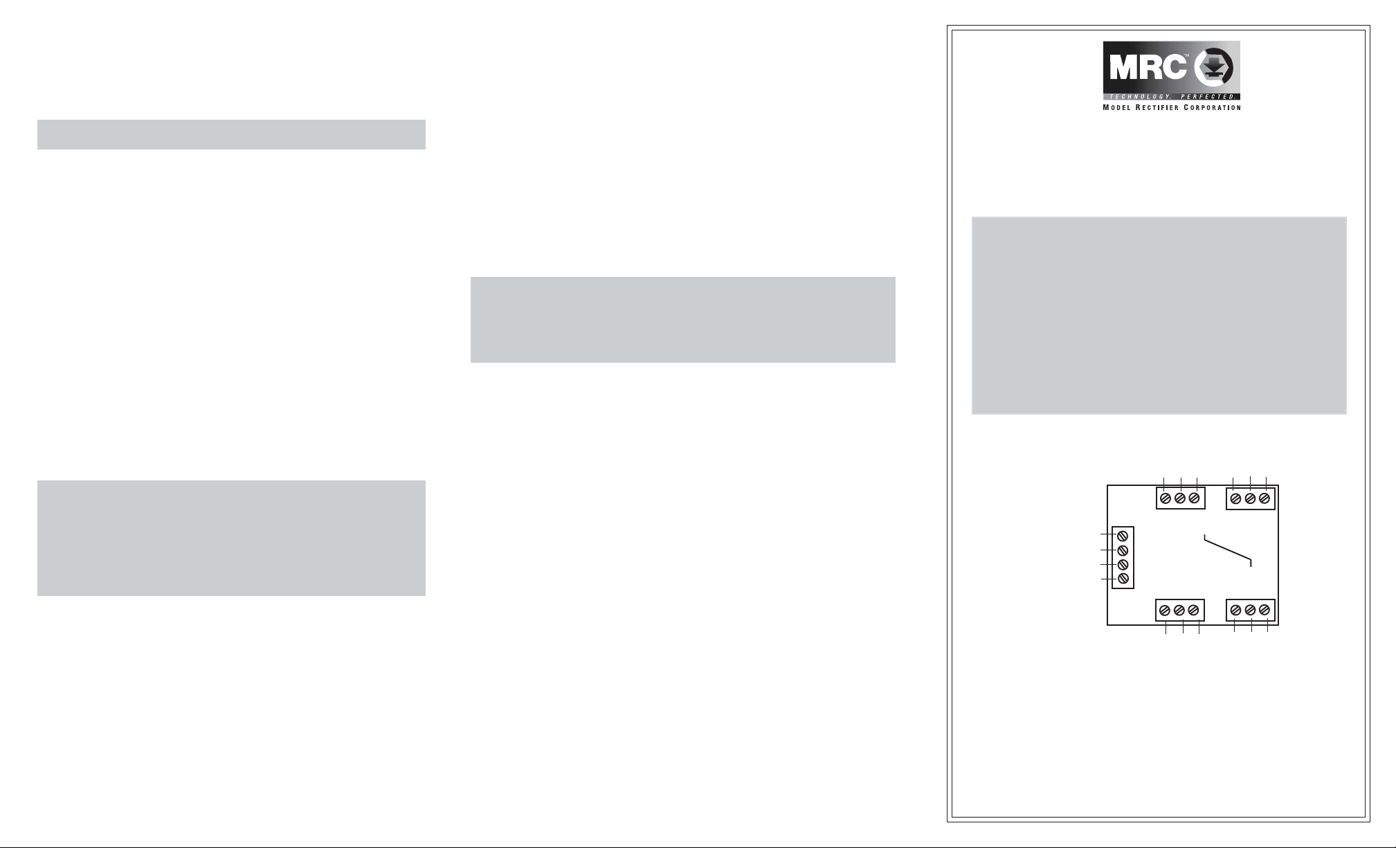
programming and have accessory decoder function capability. The MRC stationary accessory decoder comes with 4 pairs
of outputs. Think of it as 4 decoders in 1, each having its own
sub-address. The pairs are labeled as A, B, C and D (see
Diagram 1A).
(to accessory) (to accessory)
Diagram 1A
Com
output1
output2
(from power supply)
12VAC input
DCC input
(from DCC track)
Each subdecoder has three terminal hookups labeled OUTPUT 1,
COMMON, and OUTPUT 2 (see Diagram 1A). These terminal hookups go to the accessory or switch machine. Do not apply any power
to these terminals. It will damage the decoder.
This decoder gets its power and DCC signal from your DCC command
base or through the track rails. It can also power your accessories from
DCC track power or any external 12-vac power supply.
A
Red wire
C
Com
output1
(to accessory) (to accessory)
output2
Com
output1
B
D
Com
output1
output2
output2
Page 2
It is always better to power your accessories with an external power
supply so your DCC system utilizes its full power to run your trains.
This decoder also rectifies the AC power, so accessories requiring DC
current, such as slo-motion DC switch machines or LEDs, do not need a
separate DC power supply.
Hookup from your DCC system to decoder
There are 4 input terminals on the decoder board (see Diagram 1A).
1.If you do not want the DCC signal to power any accessories, run 2 wires
between your DCC unit or your track rails closest to the decoder, and the
lower 2 input terminals marked “DCC Track” (see Diagram 1A). Then
using an external 12-vac power supply, connect its 2 output wires to the
upper 2 input terminals marked “12-vac.”
The quantity and type of accessories will determine the requirements
of your 12-volt power supply.
2.If you want the DCC signal to power your accessories, run 2 wires
between your DCC unit or your track rails closest to the decoder, and
the lower 2 input terminals, and then jump them from the two lower
input terminals to the upper two input terminals (see Diagram 1B).
Remember, if you use this method to power your accessories, you
will have less power to operate your trains. (Diagram 1B)
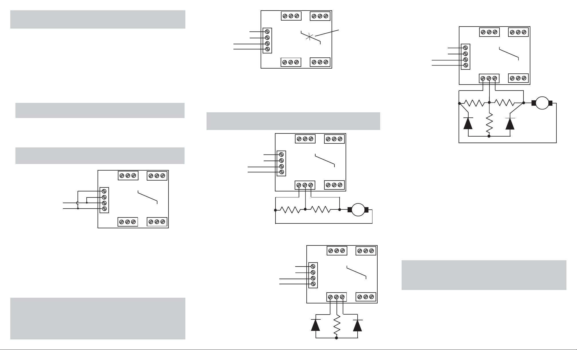
Diagram 1B
B
D
From DCC track
A
Red wire
C
Hooking up your accessory decoder to twin coil (AC) switch
machines
Your accessory decoder comes from the factory pre-programmed to
operate in latching mode, “Constant On.” However, twin coil switch
machines use a momentary pulse to activate them.
If left in the “Constant On” output, the decoder will burn out the switch
machines. Please reprogram the accessory decoder to operate the twincoil switch machines prior to hooking them up to the accessory decoder.
See section on programming the decoder.
If you are going to use the accessory decoder solely for twin-coil switch
machines, cutting the red wire will automatically set the decoder for use
of this type of switch machine. All you need to program is its program
address. See section on programming and Diagram 2. Twin-coil switch
machine has three terminals or wires. Usually the middle one is common. Make sure the common wire is connected to the Com terminal.
Diagram 2
A
C
B
D
Red wire
Cut this red wire if
the decoder is used
only for twin coil
switch machine
B
D
Slo-motion
switch machine
A
Red wire
A
From 12V power supply
From DCC track
Red wire
C
Hooking up your accessory decoder to a slo-motion switch machine
(DC) or signal LEDs (DC)
Your accessory decoder rectifies the AC input so an auxiliary DC power
supply is not needed, just an AC power supply can be used for DC
accessories. Follow Diagram 3 for each pair of the four outputs (A-B-C-D).
The decoder is shipped with four pieces of 300-ohm resistors for use
with slo-motion switch machines or signal LEDs.
Diagram 3
From 12V power supply
From DCC track
Hooking up LEDs only
Diagram 4
From 12V power supply
From DCC track
C
Use the supplied resistors to hook up
signal LEDs to the four pairs of
outputs (A-B-C-D) of your accessory
decoders.
LED1 LED2
M
B
D
Using LEDs and slo-motion switch machine from same decoder
pairs of output (A-B-C-D) (Diagram 5)
Diagram 5
B
D
Slo-motion
switch machine
From 12V power supply
From DCC track
A
Red wire
C
M
LED1
Programming the decoder
This decoder has the following CVs:
CV513 – main address that is a 2 digit (1-127) address
CV515 – The output mode of Pair A (subdecoder A)
CV516 – The output mode of Pair B (subdecoder B)
CV517 – The output mode of Pair C (subdecoder C)
CV518 – The output mode of Pair D (subdecoder D)
If your DCC system cannot program CV513 to CV518, you can use
CV1 to CV6 to program the decoder on the program track. The CV
mapping follows:
CV1 = CV513 = main address
CV3 = CV515 = pair A output mode
CV4 = CV516 = pair B output mode
CV5 = CV517 = pair C output mode
CV6 = CV518 = pair D output mode
Programming
During the programming mode, you cannot program reverse polarity
into the accessory decoder. You can only reverse the polarity of a
specific output when you program a route for your accessory
decoders on your DCC system.
Programming address CV513:
The main address can only be programmed on the program track.
This main address, once programmed, automatically assigns the
four outputs their sub-addresses, so you need only to program one
address to the decoder. Your decoder’s main address is preprogrammed to #1 at the factory. So the sub-addresses are 1, 2, 3
and 4.
LED2
 Loading...