

MR VACUTAP VR I HD-Ex, VACUTAP VR I-Ex, VACUTAP VR II-Ex, VACUTAP VR III-Ex Installation And Commissioning Instructions
Page 1
On-Load Tap-Changer
VACUTAP® VR I HD-Ex
Installation and Commissioning Instructions
5293014/00 EN
Page 2

© All rights reserved by Maschinenfabrik Reinhausen
Dissemination and reproduction of this document and use and disclosure of its content are strictly prohibited
unless expressly permitted.
Infringements will result in liability for compensation. All rights reserved in the event of the granting of patents,
utility models or designs.
The product may have been altered since this document was published.
We reserve the right to change the technical data, design and scope of supply.
Generally the information provided and agreements made when processing the individual quotations and orders
are binding.
The original operating instructions were written in German.
Page 3

Table of contents
Table of contents
1 Introduction......................................................................................................................... 8
1.1 Manufacturer....................................................................................................................................... 8
1.2 Subject to change without notice......................................................................................................... 8
1.3 Completeness...................................................................................................................................... 8
1.4 Safekeeping......................................................................................................................................... 9
1.5 Notation conventions........................................................................................................................... 9
1.5.1 Symbols................................................................................................................................................................. 9
1.5.2 Hazard communication system........................................................................................................................... 10
1.5.3 Information system.............................................................................................................................................. 11
2 Safety................................................................................................................................. 13
2.1 Appropriate use................................................................................................................................. 13
2.2 Fundamental safety instructions........................................................................................................ 14
2.3 Standards and regulations................................................................................................................. 15
2.3.1 Application range of the on-load tap-changer..................................................................................................... 15
2.3.2 Standards and regulations.................................................................................................................................. 18
2.4 Measures for ensuring compliance with explosion protection requirements..................................... 18
2.4.1 Measures taken by the manufacturer.................................................................................................................. 18
2.4.2 Measures to be taken by the transformer manufacturer/operator....................................................................... 18
2.5 Personnel qualification...................................................................................................................... 22
2.6 Personal protective equipment.......................................................................................................... 23
3 Product description.......................................................................................................... 25
3.1 Scope of delivery............................................................................................................................... 25
3.2 On-load tap-changer.......................................................................................................................... 25
3.2.1 Function description............................................................................................................................................ 25
3.2.2 Setup/models...................................................................................................................................................... 26
3.2.3 Name plate.......................................................................................................................................................... 31
3.3 Drive shaft......................................................................................................................................... 31
3.3.1 Function description............................................................................................................................................ 31
3.3.2 Design/Model...................................................................................................................................................... 33
3.3.3 Identification plate............................................................................................................................................... 35
3.4 Protective relay.................................................................................................................................. 35
3.4.1 Function description............................................................................................................................................ 35
3.4.2 Setup/versions..................................................................................................................................................... 36
Maschinenfabrik Reinhausen GmbH 2017 35293014/00 EN VACUTAP® VR I HD-Ex
Page 4

Table of contents
3.4.3 Name plate.......................................................................................................................................................... 37
4 Packaging, transport and storage................................................................................... 38
4.1 Packaging.......................................................................................................................................... 38
4.1.1 Suitability............................................................................................................................................................. 38
4.1.2 Markings.............................................................................................................................................................. 38
4.2 Transportation, receipt and handling of shipments............................................................................ 39
4.3 Storage of shipments......................................................................................................................... 40
4.4 Unpacking shipments and checking for transportation damages...................................................... 41
5 Mounting............................................................................................................................ 42
5.1 Preparatory work............................................................................................................................... 42
5.1.1 Fitting mounting flange on transformer cover...................................................................................................... 43
5.1.2 Fitting stud bolts on mounting flange................................................................................................................... 43
5.2 Installing the standard version on-load tap-changer in the transformer............................................ 44
5.2.1 Fastening on-load tap-changer to transformer cover.......................................................................................... 44
5.2.2 Connecting the tap winding and on-load tap-changer take-off lead.................................................................... 56
5.2.3 Carrying out transformer ratio test before drying................................................................................................. 64
5.2.4 Measuring DC resistance on transformer............................................................................................................ 65
5.2.5 Drying on-load tap-changer in autoclave............................................................................................................. 66
5.2.6 Drying on-load tap-changer in transformer tank.................................................................................................. 68
5.2.7 Carrying out transformer ratio test after drying.................................................................................................... 89
5.3 Installing on-load tap-changer in transformer (bell-type tank version)............................................... 90
5.3.1 Inserting on-load tap-changer into supporting structure...................................................................................... 90
5.3.2 Connecting the tap winding and on-load tap-changer take-off lead.................................................................. 100
5.3.3 Carrying out transformer ratio test before drying............................................................................................... 108
5.3.4 Measuring DC resistance on transformer.......................................................................................................... 109
5.3.5 Drying on-load tap-changer in autoclave........................................................................................................... 110
5.3.6 Lifting top part of on-load tap-changer head off supporting flange (bottom part).............................................. 112
5.3.7 Fit the bell-type tank and connect the on-load tap-changer to the top part of the on-load tap-changer head... 121
5.3.8 Drying on-load tap-changer in transformer tank................................................................................................ 134
5.3.9 Carrying out transformer ratio test after drying.................................................................................................. 156
5.4 Filling the oil compartment of the on-load tap-changer with oil....................................................... 157
5.5 Fitting protective devices and drive components............................................................................. 158
5.5.1 Connecting the tap-change supervisory device................................................................................................ 158
5.5.2 Installing protective relay in piping and connecting........................................................................................... 159
5.5.3 Fitting motor-drive unit....................................................................................................................................... 168
Maschinenfabrik Reinhausen GmbH 20174 5293014/00 ENVACUTAP® VR I HD-Ex
Page 5

Table of contents
5.5.4 Fitting drive shaft............................................................................................................................................... 168
5.5.5 Centering on-load tap-changer and motor-drive unit......................................................................................... 192
5.5.6 Installing electrics for motor-drive unit............................................................................................................... 192
6 Commissioning the on-load tap-changer at the transformer manufacturer's site... 193
6.1 Bleeding on-load tap-changer head and suction pipe..................................................................... 193
6.1.1 Bleeding on-load tap-changer head.................................................................................................................. 193
6.1.2 Bleeding suction pipe on pipe connection S...................................................................................................... 194
6.2 Grounding the on-load tap-changer................................................................................................. 194
6.3 Performing tests on motor-drive unit............................................................................................... 196
6.4 Performing trial tap-change operations........................................................................................... 196
6.5 High-voltage tests on the transformer............................................................................................. 197
7 Transporting transformer to the operating site........................................................... 199
7.1 Transport with removed drive.......................................................................................................... 199
7.2 Transport with oil fill and without oil conservator............................................................................. 199
7.3 Transport without oil fill.................................................................................................................... 200
7.3.1 Emptying oil compartment via pipe connection S.............................................................................................. 200
8 Commissioning the transformer at the operating site................................................ 202
8.1 Checking motor-drive unit................................................................................................................ 202
8.2 Checking protective relay................................................................................................................ 203
8.2.1 Checking protective relay (RS 2001, 2001/V, 2001/H, 2001/E, 2001/5, 2001/R, 2003).................................... 203
8.2.2 Checking protective relay (RS 2004)................................................................................................................. 204
8.3 Filling the oil compartment of the on-load tap-changer with oil....................................................... 204
8.4 Bleeding on-load tap-changer head and suction pipe..................................................................... 206
8.4.1 Bleeding on-load tap-changer head.................................................................................................................. 206
8.4.2 Bleeding suction pipe on pipe connection S...................................................................................................... 207
8.5 Performing trial tap-change operations........................................................................................... 207
8.6 Commissioning the transformer....................................................................................................... 208
9 Fault elimination.............................................................................................................. 209
9.1 Tripping of the protective relay and re-commissioning the transformer........................................... 211
9.1.1 Flap valve in IN SERVICE position................................................................................................................... 212
9.1.2 Flap valve in OFF position................................................................................................................................. 212
9.1.3 Re-commissioning the transformer................................................................................................................... 212
10 Technical data................................................................................................................. 213
Maschinenfabrik Reinhausen GmbH 2017 55293014/00 EN VACUTAP® VR I HD-Ex
Page 6

Table of contents
10.1 Limit values for dielectric strength and water content of on-load tap-changer oil............................ 214
10.2 Technical data for protective relay................................................................................................... 215
10.2.1 Protective relay with several dry-reed magnetic switches................................................................................. 216
11 Drawings.......................................................................................................................... 217
11.1 VACUTAP® VRC/VRE-Ex, installation drawing (899992)............................................................... 217
11.2 VACUTAP® VRC/VRE-Ex, installation drawing (743600)............................................................... 218
11.3 VACUTAP® VRD/VRF-Ex, installation drawing (899898)............................................................... 219
11.4 VACUTAP® VRD/VRF-Ex, installation drawing (743601)............................................................... 220
11.5 VACUTAP® VRG-Ex, installation drawing (899945)....................................................................... 221
11.6 VACUTAP® VRG-Ex, installation drawing (743602)....................................................................... 222
11.7 VACUTAP® VRC/VRE-Ex, installation position of tap selector connection contacts (727042)...... 223
11.8 VACUTAP® VRC/VRE-Ex, installation position of tap selector connection contacts (743603)...... 224
11.9 VACUTAP® VRD/VRF/VRG-Ex, fine tap selector connection contact and change-over selector
connection contact (899941)........................................................................................................... 225
11.10 VACUTAP® VR-Ex, special design for bell-type tank installation (720781).................................... 226
11.11 VACUTAP® VR-Ex, lifting device for bell-type tank installation (720845)....................................... 227
11.12 VACUTAP® VR-Ex, on-load tap-changer head (720847)............................................................... 228
11.13 Pipe connection Q with tap-change supervisory control (766161).................................................. 229
11.14 VACUTAP® VR-Ex, adjustment positions (728557)....................................................................... 230
11.15 VACUTAP® VRC/VRE-Ex, adjustment plan without change-over selector (719853)..................... 231
11.16 VACUTAP® VRC/VRE-Ex, adjustment plan without change-over selector (742422)..................... 233
11.17 VACUTAP® VRD/VRF-Ex, adjustment plan without change-over selector (721089)..................... 235
11.18 VACUTAP® VRD/VRF-Ex, adjustment plan without change-over selector (742423)..................... 237
11.19 VACUTAP® VRC III/VRC II/VRE III-Ex, adjustment plan with reversing change-over selector
connection (719850)........................................................................................................................ 239
11.20 VACUTAP® VRC I/VRE I-Ex, adjustment plan with reversing change-over selector connection
(719851).......................................................................................................................................... 240
11.21 VACUTAP® VRD/VRF-Ex, adjustment plan with reversing change-over selector connection
(721092).......................................................................................................................................... 241
11.22 VACUTAP® VRD/VRF-Ex, adjustment plan with reversing change-over selector connection
(745024).......................................................................................................................................... 242
11.23 VACUTAP® VRG-Ex, adjustment plan with reversing change-over selector connection (727074).......
243
11.24 VACUTAP® VRG-Ex, adjustment plan with reversing change-over selector connection (742424).......
244
11.25 VACUTAP® VRC/VRE-Ex, adjustment plan with coarse tap selector connection (719852)........... 245
11.26 VACUTAP® VRC/VRE-Ex, adjustment plan with coarse tap selector connection (742425)........... 246
Maschinenfabrik Reinhausen GmbH 20176 5293014/00 ENVACUTAP® VR I HD-Ex
Page 7

Table of contents
11.27 Adjustment plan VACUTAP® VRC-Ex with multiple coarse change-over selector for change-over
selector division 10, 2-5 coarse tap connections (731412)............................................................. 247
11.28 Adjustment plan VACUTAP® VRC-Ex with multiple coarse change-over selector for change-over
selector division 10, 2-5 coarse tap connections (745032)............................................................. 248
11.29 Adjustment plan VACUTAP® VRC-Ex with multiple coarse change-over selector for change-over
selector division 12, 2-5 coarse tap connections (731411)............................................................. 249
11.30 Adjustment plan VACUTAP® VRC-Ex with multiple coarse change-over selector for change-over
selector division 12, 2-5 coarse tap connections (745031)............................................................. 250
11.31 Adjustment plan VACUTAP® VRC-Ex with multiple coarse change-over selector for change-over
selector division 14, 2-5 coarse tap connections (731410)............................................................. 251
11.32 Adjustment plan VACUTAP® VRC-Ex with multiple coarse change-over selector for change-over
selector division 14, 2-5 coarse tap connections (745030)............................................................. 252
11.33 Adjustment plan VACUTAP® VRC-Ex with multiple coarse change-over selector for change-over
selector division 16, 2-5 coarse tap connections (731000)............................................................. 253
11.34 Adjustment plan VACUTAP® VRC-Ex with multiple coarse change-over selector for change-over
selector division 16, 2-5 coarse tap connections (745029)............................................................. 254
11.35 Adjustment plan VACUTAP® VRC-Ex with multiple coarse change-over selector for change-over
selector division 18, 2-5 coarse tap connections (730977)............................................................. 255
11.36 Adjustment plan VACUTAP® VRC-Ex with multiple coarse change-over selector for change-over
selector division 18, 2-5 coarse tap connections (745028)............................................................. 256
11.37 VACUTAP® VRD/VRF-Ex, adjustment plan with coarse tap selector connection (721091)........... 257
11.38 VACUTAP® VRD/VRF-Ex, adjustment plan with coarse tap selector connection (742426)........... 258
11.39 VACUTAP® VRG-Ex, adjustment plan with coarse tap selector connection (727075)................... 259
11.40 VACUTAP® VRG-Ex, adjustment plan with coarse tap selector connection (742427)................... 260
11.41 Tracing template for on-load tap-changer head (890183)............................................................... 261
11.42 Socket wrench for kerosene drain plug (723015)............................................................................ 262
11.43 Screw tools for installation and maintenance (723016)................................................................... 263
11.44 Bevel gear CD 6400, dimensional drawing (892916)...................................................................... 264
Maschinenfabrik Reinhausen GmbH 2017 75293014/00 EN VACUTAP® VR I HD-Ex
Page 8

1 Introduction
Introduction
1
This technical file contains detailed descriptions of the safe and proper installation, connection, and commissioning of the product.
It also includes safety instructions and general information about the product.
Information about operation can be found in the operating instructions.
This technical file is intended solely for specially trained and authorized personnel.
Manufacturer
1.1
The product is manufactured by:
Maschinenfabrik Reinhausen GmbH
Falkensteinstraße 8
93059 Regensburg, Germany
Tel.: (+49) 9 41/40 90-0
Fax: (+49) 9 41/40 90-7001
E-mail: sales@reinhausen.com
Further information on the product and copies of this technical file are available from this address if required.
Subject to change without notice
1.2
The information contained in this technical file comprises the technical specifications approved at the time of printing. Significant modifications will be included in a new edition of the technical file.
The document number and version number of this technical file are shown in
the footer.
Completeness
1.3
This technical file is incomplete without the supporting documents.
The following documents apply:
▪ Unpacking instructions (included in the scope of delivery)
▪ Supplement (included in the scope of delivery)
▪ Routine test report (included in the scope of delivery)
▪ Connection diagrams (included in the scope of delivery)
▪ Dimensional drawings (included in the scope of delivery)
▪ Technical data - General section (available on request)
▪ Technical data - Product-specific section (available on request)
Maschinenfabrik Reinhausen GmbH 20178 5293014/00 ENVACUTAP® VR I HD-Ex
Page 9
1 Introduction
Safekeeping
1.4
Keep this technical file and all supporting documents ready at hand and accessible for future use at all times.
Notation conventions
1.5
This section contains an overview of the symbols and textual emphasis
used.
1.5.1
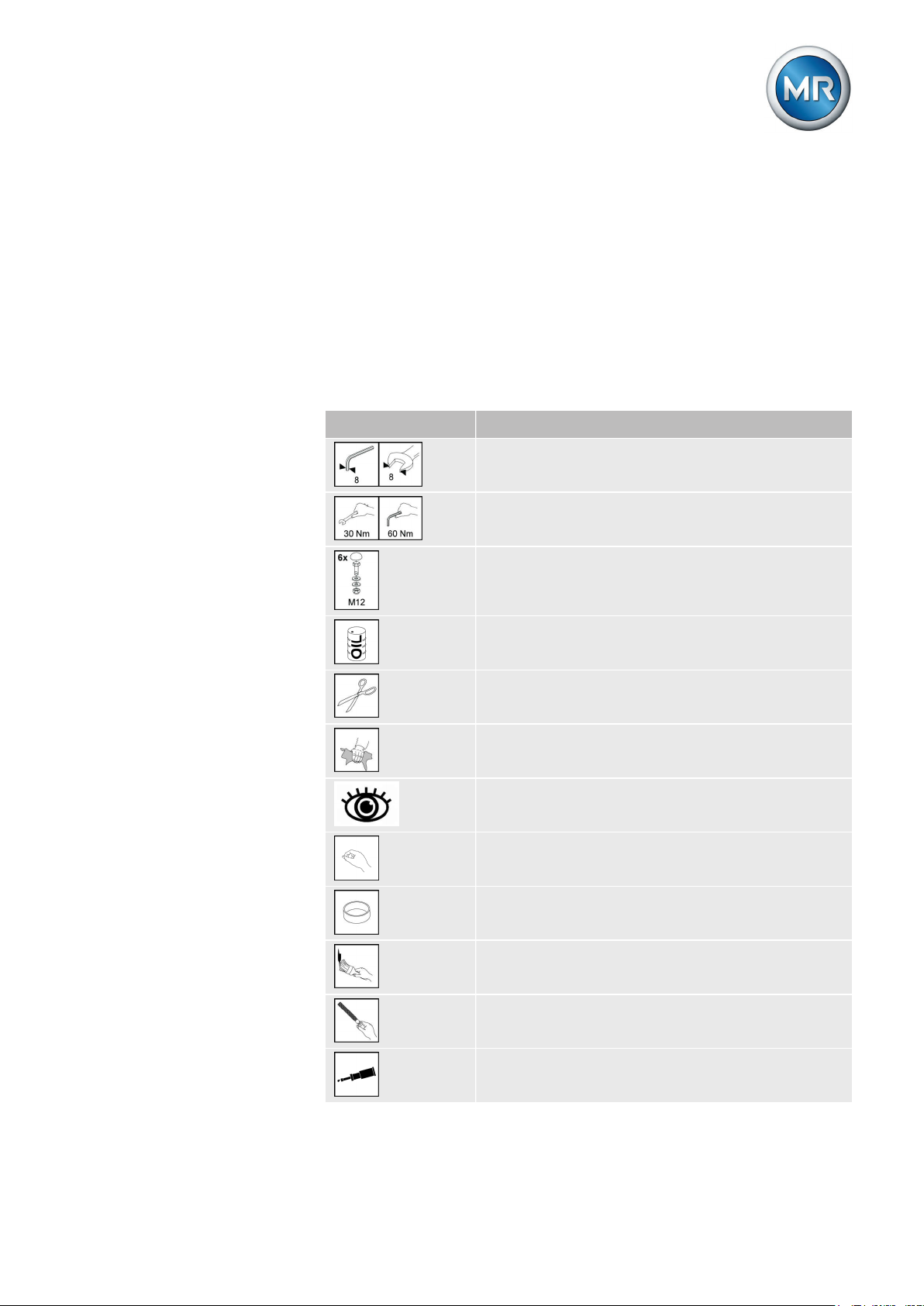
Symbols
Symbol Meaning
Wrench size
Tightening torque
Number and type of fastening material used
Fill with oil
Cut open, cut through
Clean
Visual inspection
Use your hand
Adapter ring
Apply a coat of paint
Use a file
Grease
Maschinenfabrik Reinhausen GmbH 2017 95293014/00 EN VACUTAP® VR I HD-Ex
Page 10
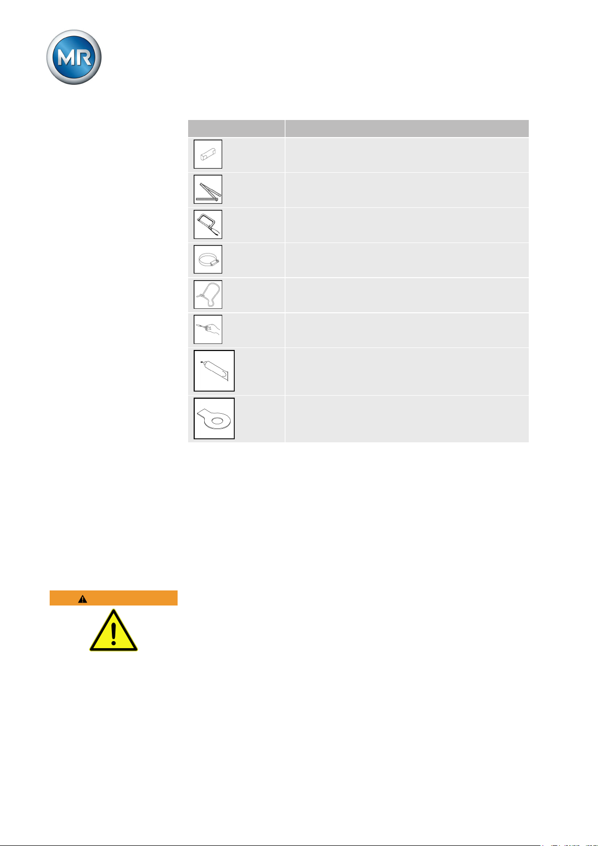
Symbol Meaning
Coupling bolt
Use a ruler
Use a saw
Hose clip
Wire eyelet, safety wire
Use a screwdriver
1 Introduction
WARNING
1.5.2
1.5.2.1
Apply adhesive
Lock tab
Table 1: Symbols
Hazard communication system
Warnings in this technical file are displayed as follows.
Warning relating to section
Warnings relating to sections refer to entire chapters or sections, sub-sections or several paragraphs within this technical file. Warnings relating to
sections use the following format:
Type and source of danger
Consequences
► Action
► Action
1.5.2.2
Embedded warning information
Embedded warnings refer to a particular part within a section. These warnings apply to smaller units of information than the warnings relating to sections. Embedded warnings use the following format:
Maschinenfabrik Reinhausen GmbH 201710 5293014/00 ENVACUTAP® VR I HD-Ex
Page 11
1 Introduction
DANGER! Instruction for avoiding a dangerous situation.
1.5.2.3
Signal words and pictograms
The following signal words are used:
Signal
Meaning
word
DANGER Indicates a hazardous situation which, if not avoided, will
result in death or serious injury.
WARNING Indicates a hazardous situation which, if not avoided, could
result in death or serious injury.
CAUTION Indicates a hazardous situation which, if not avoided, could
result in injury.
NOTICE Indicates measures to be taken to prevent damage to
property.
Table 2: Signal words in warning notices
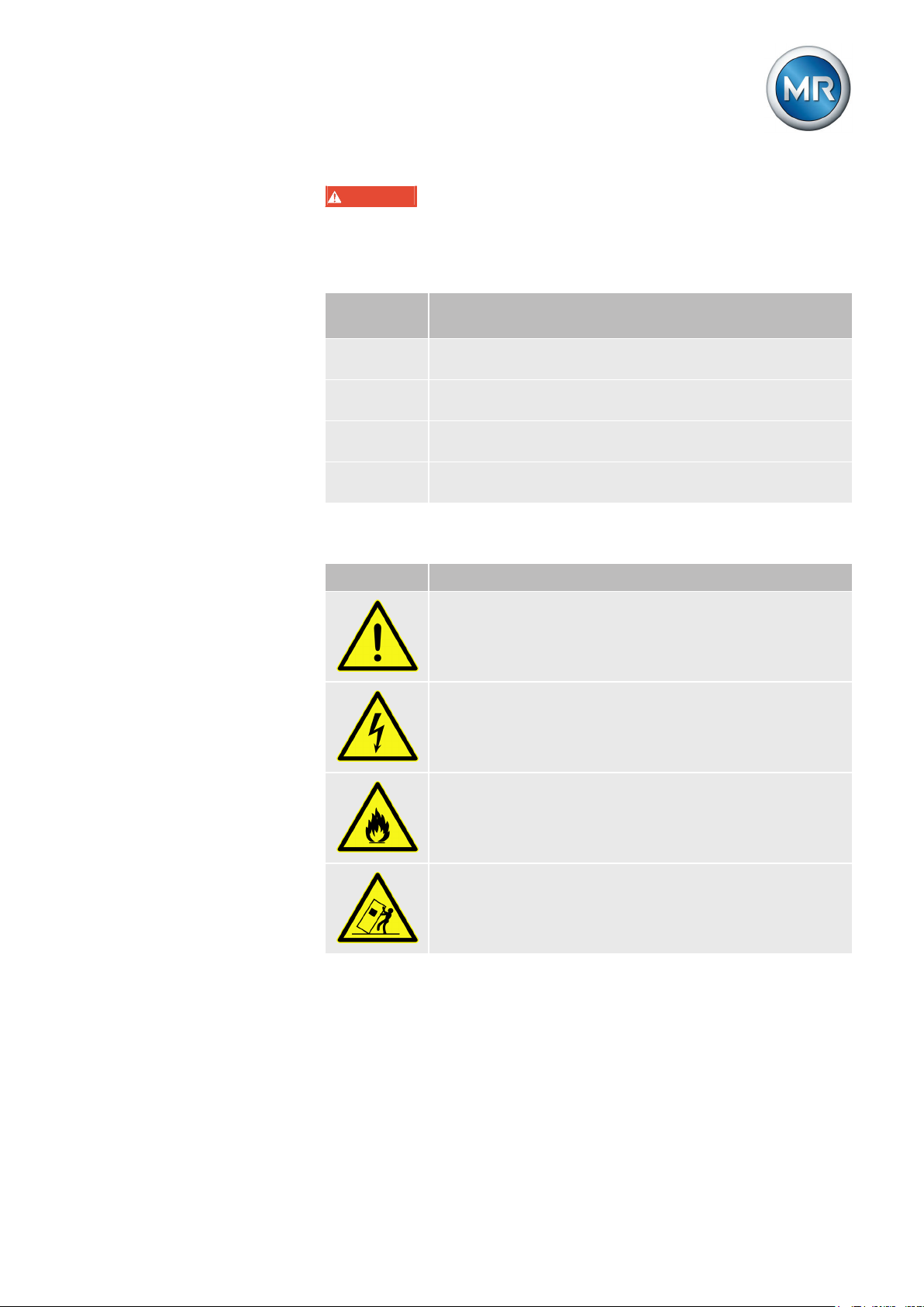
Pictograms warn of dangers:
Pictogram Meaning
Warning of a danger point
Warning of dangerous electrical voltage
1.5.3
Warning of combustible substances
Warning of danger of tipping
Table 3: Pictograms used in warning notices
Information system
Information is designed to simplify and improve understanding of particular
procedures. In this technical file it is laid out as follows:
Maschinenfabrik Reinhausen GmbH 2017 115293014/00 EN VACUTAP® VR I HD-Ex
Page 12

Important information.
1 Introduction
Maschinenfabrik Reinhausen GmbH 201712 5293014/00 ENVACUTAP® VR I HD-Ex
Page 13

2 Safety
Safety
2
This technical file contains detailed descriptions on the safe and proper installation, connection, commissioning and monitoring of the product.
▪ Read this technical file through carefully to familiarize yourself with the
product.
▪ This technical file is part of the product.
▪ Read and observe the safety instructions provided in this chapter in par-
ticular.
▪ Observe the warnings in this technical file in order to avoid function-re-
lated dangers.
▪ The product is manufactured on the basis of state-of-the-art technology.
Nevertheless, risks to life and limb of the user or impairment of the product and other material assets may occur during use due to function-related dangers.
Appropriate use
2.1
The product is an on-load tap-changer and keeps the output voltage of a
transformer constant. The product is designed solely for use in electrical energy systems and facilities. If used as intended and in compliance with the
requirements and conditions specified in this technical file as well as the
warning notices in this technical file and attached to the product, then the
product does not present any danger to people, property or the environment.
This applies across the entire service life of the product, from delivery to installation and operation through to disassembly and disposal.
The following is considered appropriate use:
▪ Use the product only with the transformer specified in the order.
▪ The serial numbers of on-load tap-changers and on-load tap-changer
accessories (drive, drive shaft, bevel gear, protective relay, etc.) must
match if the on-load tap-changers and on-load tap-changer accessories
are supplied as a set for one order.
▪ You will find the standard valid for the product and the year of issue on
the nameplate.
▪ Operate the product in accordance with this technical file, the agreed-
upon delivery conditions and the technical data.
▪ Ensure that all necessary work is performed by qualified personnel only.
▪ Only use the equipment and special tools included in delivery for the in-
tended purpose and in accordance with the specifications of this technical file.
▪ The on-load tap-changer is not intended to be used with an oil filter unit.
▪ The measures described in this technical file must be taken in order to
comply with explosion protection requirements.
Maschinenfabrik Reinhausen GmbH 2017 135293014/00 EN VACUTAP® VR I HD-Ex
Page 14

Fundamental safety instructions
2.2
To prevent accidents, disruptions and damage as well as unacceptable adverse effects on the environment, those responsible for transport, installation, operation, maintenance and disposal of the product or parts of the product must ensure the following:
Personal protective equipment
Loosely worn or unsuitable clothing increases the danger of becoming trapped or caught up in rotating parts and the danger of getting caught on protruding parts. This increases the danger to life and limb.
▪ All necessary devices and personal protective equipment required for
the specific task, such as a hard hat, safety footwear, etc. must be worn.
Observe the section "Personal protective equipment" [► 23].
▪ Never wear damaged personal protective equipment.
▪ Never wear rings, necklaces, or other jewelry.
▪ If you have long hair, wear a hairnet.
2 Safety
Work area
Untidy and poorly lit work areas can lead to accidents.
▪ Keep the work area clean and tidy.
▪ Make sure that the work area is well lit.
▪ Observe the applicable laws for accident prevention in the relevant
country.
Working during operation
You must only operate the product when it is in a sound operational condition. Otherwise it poses a danger to life and limb.
▪ Regularly check the operational reliability of safety equipment.
▪ Comply with the maintenance work and maintenance intervals descri-
bed in this technical file.
Explosion protection
Highly flammable or explosive gases, vapors and dusts can cause serious
explosions and fire.
▪ Do not install the product in potentially explosive areas.
Safety markings
Warning signs and safety information plates are safety markings on the
product. They are an important aspect of the safety concept.
▪ Observe all safety markings on the product.
▪ Make sure all safety markings on the product remain intact and legible.
▪ Replace safety markings that are damaged or missing.
Maschinenfabrik Reinhausen GmbH 201714 5293014/00 ENVACUTAP® VR I HD-Ex
Page 15

2 Safety
Ambient conditions
To ensure reliable and safe operation, the product must only be operated
under the ambient conditions specified in the technical data.
▪ Observe the specified operating conditions and requirements for the in-
stallation location.
Auxiliary materials and operating materials
Auxiliary materials and operating materials not approved by Maschinenfabrik
Reinhausen GmbH could damage the product.
▪ Only use lubricants and auxiliary materials approved by the manufactur-
er.
▪ Contact Maschinenfabrik Reinhausen GmbH.
Modifications and conversions
Unauthorized or inappropriate changes to the product may lead to personal
injury, material damage and operational faults.
▪ Only modify product following consultation with Maschinenfabrik Rein-
hausen GmbH.
2.3
2.3.1
Spare parts
Spare parts not approved by Maschinenfabrik Reinhausen GmbH may
cause physical injury and damage the product.
▪ Only use spare parts approved by the manufacturer.
▪ Contact Maschinenfabrik Reinhausen GmbH.
Standards and regulations
The standards and regulations which apply to the explosion-protected product are described in the following chapters.
Application range of the on-load tap-changer
The on-load tap-changer is certified for Ex II 3G Ex nAC IIC T3 Gc. Refer to
the following overview for the resulting application range.
1 2 3 4 5 6 7 8
II 3G Ex nAC IIC T3 Gc
Table 4: Example of the application range
Number Meaning
1 Sign for explosion protection
2 Equipment group
3 Equipment category
Maschinenfabrik Reinhausen GmbH 2017 155293014/00 EN VACUTAP® VR I HD-Ex
Page 16

Number Meaning
4 Ex: Symbol for explosion-protected equipment
5 Ignition protection type
6 Explosion group
7 Temperature class
8 EPL (Equipment Protection Level)
Equipment groups (number 2)
I Equipment in this category is intended for use in under-
ground parts of mines as well as those parts of surface installations of such mines endangered by firedamp and/or
combustible dust.
II Equipment in this category is intended for use in other
areas in which explosive atmospheres may be present.
Table 5: Equipment groups
2 Safety
Equipment category / zone classification (number 3)
Designation for
gases
1G
(0)
Designation for
dusts
1D
(20)
Definition
Equipment in this category is intended for
use in areas in which explosive atmospheres
caused by mixtures of air and gases, vapors
or mists or by air/dust mixtures are present
continuously, for long periods or frequently.
2G
(1)
2D
(21)
Equipment in this category is intended for
use in areas in which explosive atmospheres
caused by gases, vapors, mists or air/dust
mixtures occur occasionally.
3G
(2)
3D
(22)
Equipment in this category is intended for
use in areas in which explosive atmospheres
caused by gases, vapors, mists, or air/dust
mixtures are unlikely to occur or, if they do
occur, are likely to do so only infrequently
and for a short period only.
Table 6: Equipment category / zone classification
Ignition protection types (number 5)
d Pressure-proof enclosure
e Increased safety
I Intrinsic safety (ia, ib)
m Encapsulation
o Oil immersion
p Pressurized apparatus
Maschinenfabrik Reinhausen GmbH 201716 5293014/00 ENVACUTAP® VR I HD-Ex
Page 17

2 Safety
q Powder filling
n Ignition protection type "n" (only zone 2)
n A: non-sparking equipment
n C: sparking equipment with special protection for contacts
n R: vapor-protected housing
Table 7: Ignition protection types
Explosion group (number 6)
EN/IEC Gases, vapors (examples) Min. ignition energy
(mJ)
IIA Ammonia -
IIA Acetic acid, acetone, benzene,
0.18
diesel, ethane, ether, fuel oil, hexane, methane, petrol, petroleum,
propane
IIB Ethylene, isoprene, town gas 0.06
IIC Acetylene, carbon disulfide, hy-
0.02
drogen
Table 8: Explosion groups
Temperature classes (number 7)
Temperature class
Maximum equipment surface
temperature
Ignition temperature of the flammable substances
T1 450 °C > 450 °C
T2 300 °C > 300 °C < 450 °C
T3 200 °C > 200 °C < 300 °C
T4 135 °C > 135 °C < 200 °C
T5 100 °C > 100 °C < 135 °C
T6 85 °C > 85 °C < 100 °C
Table 9: Temperature classes
Equipment protection level (EPL) (number 8)
The EPL indicates the level of protection defined for a device based on the
level of probability of ignition and taking account of the differences between
potentially explosive gas atmospheres, potentially explosive dust atmospheres, and potentially explosive atmospheres in mine workings affected by
firedamp.
Maschinenfabrik Reinhausen GmbH 2017 175293014/00 EN VACUTAP® VR I HD-Ex
Page 18

2 Safety
2.3.2
2.4
2.4.1
2.4.1.1
Standards and regulations
The following standards and regulations apply to explosion-proof on-load
tap-changers:
▪ EN 60079-0: Equipment – General requirements
▪ EN 60079-15: Equipment protection by type of protection "n"
▪ Additional requirements apply to vacuum interrupters, as these are her-
metically sealed devices that generate arcs, sparks or hot surfaces.
▪ Additional requirements apply to the diverter switch oil compartment, as
this is a sealed or encapsulated device that generates arcs, sparks or
hot surfaces.
Measures for ensuring compliance with explosion protection requirements
Measures taken by the manufacturer
Maschinenfabrik Reinhausen has taken the following measures for ensuring
compliance with explosion protection requirements. You do not need to take
any special measures in this regard.
Quality of the insulating oil in the on-load tap-changer
2.4.1.2
2.4.2
The quality of the insulating oil required by IEC 60296 and the quality of the
synthetic esters required by IEC 61099 in the oil compartment of the on-load
tap-changer is ensured by using vacuum cells in transition resistors.
Monitoring the oil temperature in the diverter switch oil compartment
A temperature sensor is provided in the on-load tap-changer head cover for
monitoring the oil temperature in the diverter switch oil compartment. The
corresponding temperature monitoring relay is in the TAPMOTION® ED-Ex.
Temperature monitoring prevents further switching of the on-load tap-changer when the maximum permitted temperature is reached. This maximum permitted temperature is factory-configured for each specific order for all onload tap-changer types (maximum 130 °C) and secured against accidental
incorrect adjustment.
Measures to be taken by the transformer manufacturer/operator
The following measures for ensuring compliance with explosion protection
requirements must be taken by the transformer manufacturer/operator.
Maschinenfabrik Reinhausen GmbH 201718 5293014/00 ENVACUTAP® VR I HD-Ex
Page 19

2 Safety
2.4.2.1
Prescribed protective and drive components
Operate the on-load tap-changer only in conjunction with the following components:
▪ Ex protective relay
▪ Ex motor-drive unit
▪ Ex drive shaft
Maschinenfabrik Reinhausen GmbH 2017 195293014/00 EN VACUTAP® VR I HD-Ex
Page 20
2 Safety
2.4.2.2
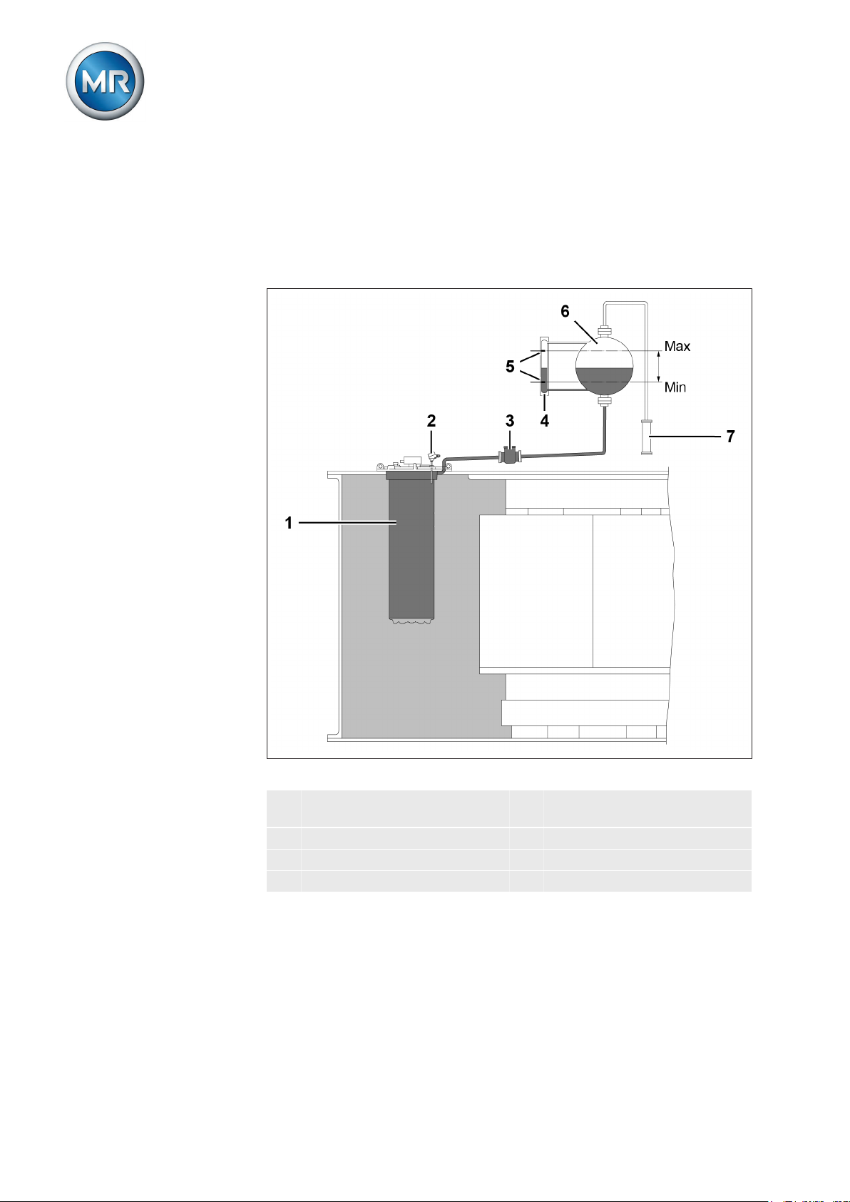
Setting up the on-load tap-changer oil system
Operate the on-load tap-changer only with a suitable oil system. This diverter switch oil system consists of the diverter switch oil compartment, protective relay, and oil conservator of the on-load tap-changer. It ensures that
enough insulating oil is present in the diverter switch oil compartment at all
times.
2.4.2.3
Figure 1: On-load tap-changer oil system
1 Diverter switch oil compart-
5 Signaling contacts
ment
2 Temperature sensor 6 Oil conservator
3 Protective relay 7 Dehydrating breather
4 Level indicator
Oil conservator to be used
The oil conservator of the on-load tap-changer ensures that sufficient insulating oil is present in the on-load tap-changer oil system at all times during
operation.
Therefore, operate the on-load tap-changer only with a oil conservator that
fulfills the following requirements:
Maschinenfabrik Reinhausen GmbH 201720 5293014/00 ENVACUTAP® VR I HD-Ex
Page 21

2 Safety
2.4.2.3.1
2.4.2.3.2
2.4.2.3.3
2.4.2.3.4
Dehydrating breather
The oil conservator must be equipped with a dehydrating breather in accordance with VDE 0532-216-5. The dehydrating breather prevents water, impurities, insects etc. from entering the insulating oil.
Level indicator
The oil conservator must have a level indicator from which the minimum oil
quantity required and the maximum quantity permitted, as well as the current
oil level, can be read.
Level monitoring
The oil level in the oil conservator must be monitored at all times during operation. Therefore, loop the signaling contact for falling below the minimum
oil level in the on-load tap-changer's oil conservator to the tripping circuit of
the circuit breaker so that the circuit breaker will immediately de-energize the
transformer when the oil level in the oil conservator falls below this minimum.
Insulating oil to be used
When filling the diverter switch oil compartment and its oil conservator, use
only new mineral insulating oil for transformers in accordance with IEC
60296 (Specification for unused mineral insulating oils for transformers and
switchgear) or synthetic ester in accordance with IEC 61099 (Specifications
for unused synthetic organic esters for electrical purposes).
2.4.2.3.5
Checking the quality of the insulating oil in the Ex transformer
During the tap changes, polarity sparks (low energy) may occur at the tap
selector of the on-load tap-changer in the transformer tank. In this regard,
observe Section 5.1.6 and 5.1.7 in the on-load tap-changer standard IEC
60214.
Therefore, check the quality and dielectric strength of the insulating oil in the
transformer tank on a regular basis and comply with the service intervals for
the oil change.
Maschinenfabrik Reinhausen GmbH 2017 215293014/00 EN VACUTAP® VR I HD-Ex
Page 22
2 Safety
2.4.2.4
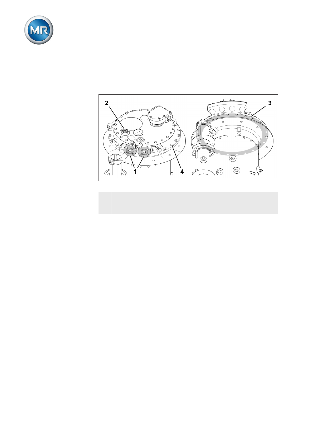
Corrosion protection measures
Because further installation steps are required before operation of the onload tap-changer, sufficient corrosion protection cannot be provided at certain interfaces to the transformer when the device leaves the factory.
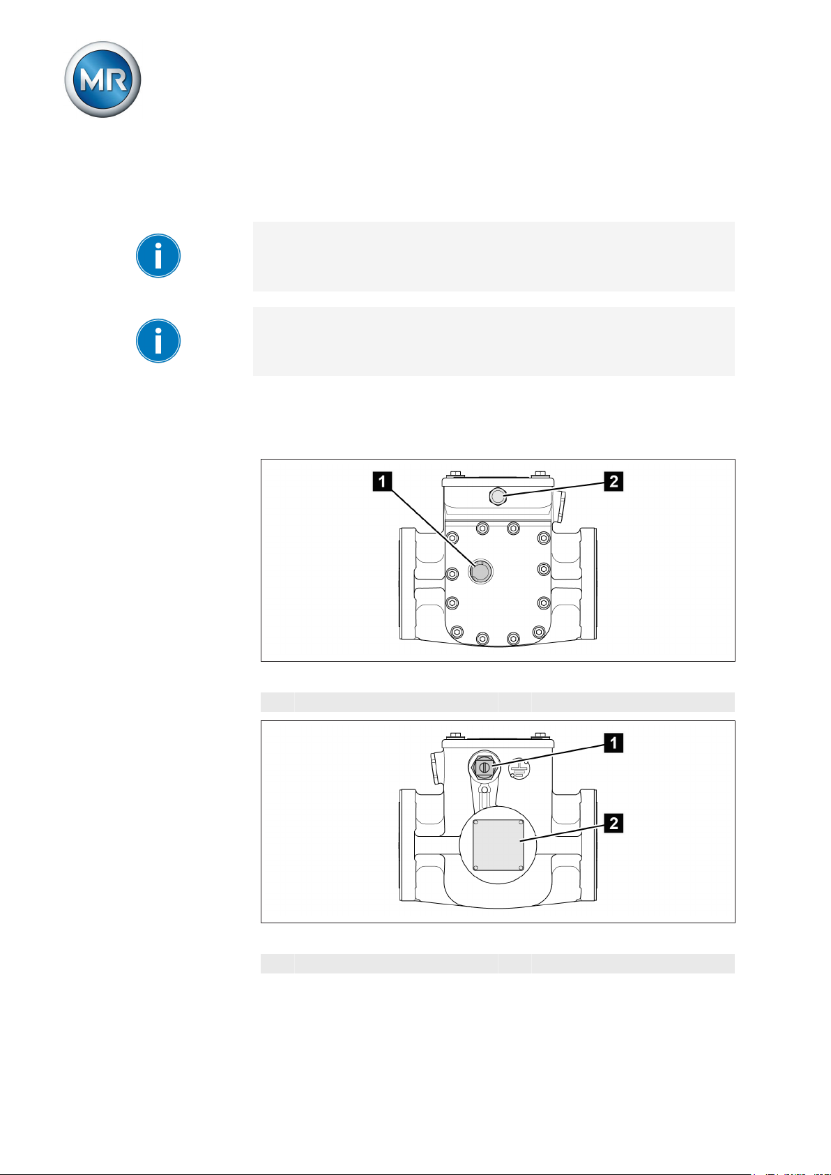
Figure 2: On-load tap-changer head
1 Sealing surface on piping con-
nection flange
2 Air-vent valve 4 Through-holes
3 Contact surface on on-load
tap-changer head
The sealing surfaces on the piping connection flange are zinc-plated ex factory. The through-holes are zinc-plated and partially painted.
The contact surface of the on-load tap-changer head is primed ex factory.
The through-holes are primed and partially painted.
The transformer manufacturer is responsible for the design of the mating
surfaces on the transformer and piping and that of the screw connections
needed for these attachments.
1. Provide suitable sealing to prevent electrolytes from entering sealing
surfaces and holes.
2. Design screws, washers, nuts etc. in A4 in accordance with ISO
3506-1/ISO 3506-2 standard.
3. If the painted surfaces are damaged, note repair instructions. These can
be requested from Maschinenfabrik Reinhausen GmbH's Technical
Service department.
Personnel qualification
2.5
The person responsible for assembly, commissioning, operation, maintenance and inspection must ensure that the personnel are sufficiently qualified.
Maschinenfabrik Reinhausen GmbH 201722 5293014/00 ENVACUTAP® VR I HD-Ex
Page 23

2 Safety
Electrically skilled person
The electrically skilled person has a technical qualification and therefore has
the required knowledge and experience, and is also conversant with the applicable standards and regulations. The electrically skilled person is also proficient in the following:
▪ Can identify potential dangers independently and is able to avoid them.
▪ Is able to perform work on electrical systems.
▪ Is specially trained for the working environment in which (s)he works.
▪ Must satisfy the requirements of the applicable statutory regulations for
accident prevention.
Electrically trained persons
An electrically trained person receives instruction and guidance from an
electrically skilled person in relation to the tasks undertaken and the potential dangers in the event of inappropriate handling as well as the protective
devices and safety measures. The electrically trained person works exclusively under the guidance and supervision of an electrically skilled person.
Operator
The operator uses and operates the product in line with this technical file.
The operating company provides the operator with instruction and training
on the specific tasks and the associated potential dangers arising from improper handling.
Technical Service
We strongly recommend having maintenance, repairs and retrofitting carried
out by our Technical Service department. This ensures that all work will be
performed correctly. If maintenance is not carried out by our Technical Service department, please ensure that the personnel who carry out the maintenance are trained and authorized by Maschinenfabrik Reinhausen GmbH to
carry out the work.
Authorized personnel
Authorized personnel are trained by Maschinenfabrik Reinhausen GmbH to
carry out special maintenance.
Personal protective equipment
2.6
Personal protective equipment must be worn during work to minimize risks to
health.
▪ Always wear the personal protective equipment required for the job at
hand.
▪ Never wear damaged personal protective equipment.
▪ Observe information about personal protective equipment provided in
the work area.
Maschinenfabrik Reinhausen GmbH 2017 235293014/00 EN VACUTAP® VR I HD-Ex
Page 24

2 Safety
Personal protective equipment to be worn at all times
Protective clothing
Close-fitting work clothing with a low tearing strength, with tight sleeves and with no
protruding parts. It mainly serves to protect the wearer against being caught by
moving machine parts.
Safety shoes
To protect against falling heavy objects
and slipping on slippery surfaces.
Special personal protective equipment for particular environments
Safety glasses
To protect the eyes from flying parts and
splashing liquids.
Visor
To protect the face from flying parts and
splashing liquids or other dangerous substances.
Hard hat
To protect from falling and flying parts and
materials.
Hearing protection
To protect from hearing damage.
Protective gloves
To protect from mechanical, thermal, and
electrical hazards.
Maschinenfabrik Reinhausen GmbH 201724 5293014/00 ENVACUTAP® VR I HD-Ex
Page 25

3 Product description
Product description
3
This chapter contains an overview of the design and function of the product.
Scope of delivery
3.1
The product is packaged with protection against moisture and is usually delivered as follows:
▪ Oil compartment with on-load tap-changer head and built-in diverter
switch insert
▪ Selector
▪ Ex motor-drive unit
▪ Ex drive shaft with coupling parts and bevel gear
▪ Ex protective relay
▪ Technical files
Please refer to the delivery slip for full details of scope of delivery.
Single-phase on-load tap-changers are also available as an on-load tapchanger set with a common motor-drive unit.
3.2.1
Note the following information:
▪ Check the shipment for completeness on the basis of the shipping docu-
ments.
▪ Store the parts in a dry place until installation
▪ The product must remain in its airtight, protective wrapping and may on-
ly be removed immediately before installation
You will find more information in the "Packaging, transport, and storage"
[► 38] chapter.
On-load tap-changer
3.2
Function description
On-load tap-changers are used to adjust the transmission ratio of transformers without interrupting the load flow. Fluctuations in voltage occurring in the
power transmission grid, for example, can therefore be compensated for. For
this purpose, on-load tap-changers are fitted in transformers and connected
to the active part of the transformer.
Maschinenfabrik Reinhausen GmbH 2017 255293014/00 EN VACUTAP® VR I HD-Ex
Page 26
3 Product description
A motor-drive unit, which receives a control impulse (e.g. from a voltage regulator), changes the on-load tap-changer's operating position, which adapts
the transmission ratio of the transformer to the respective operating requirements.
3.2.2
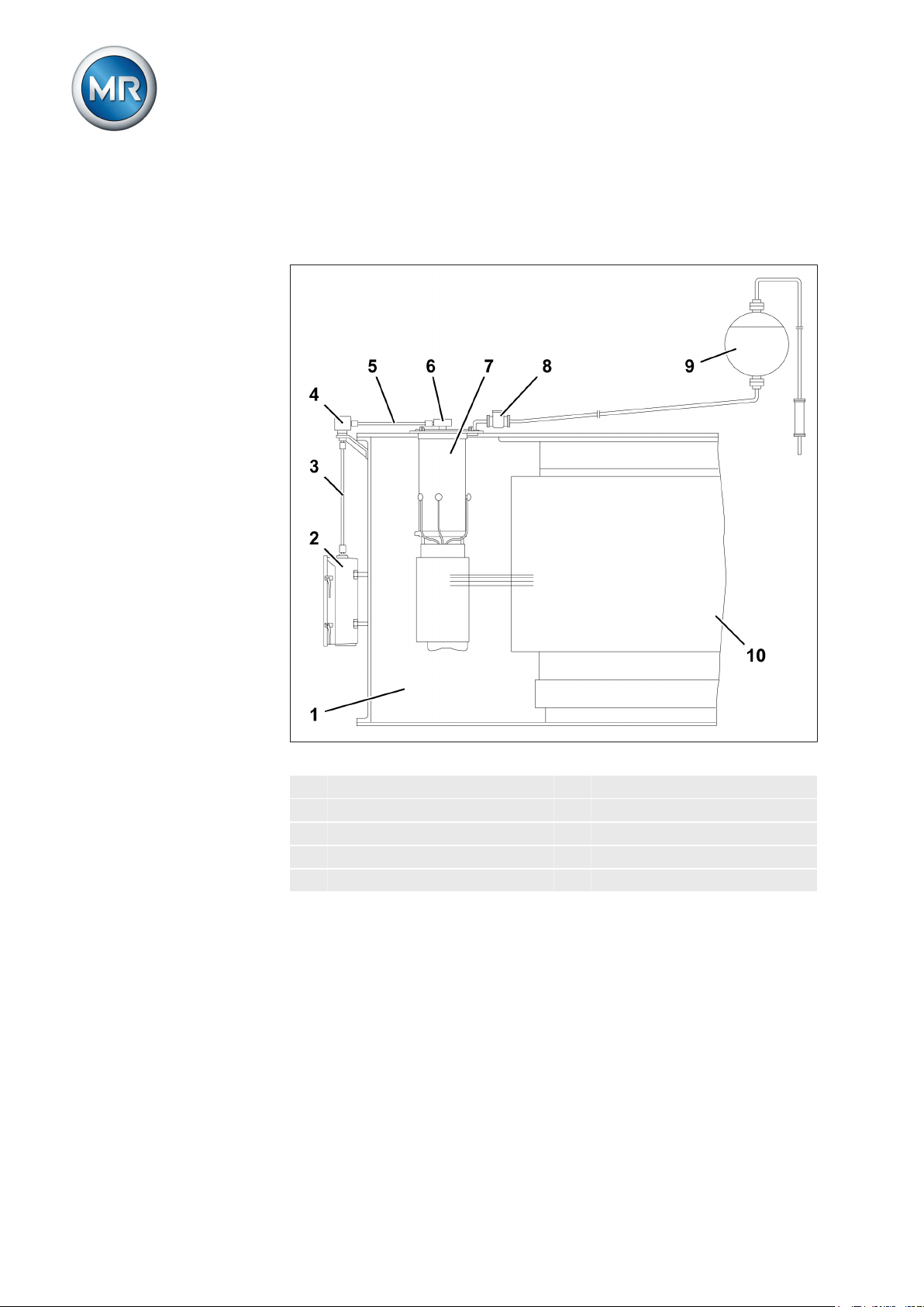
Figure 3: System overview of on-load tap-changer Transformer
1 Transformer tank 6 Upper gear unit
2 Motor-drive unit 7 On-load tap-changer
3 Vertical drive shaft 8 RS protective relay
4 Bevel gear 9 Oil conservator
5 Horizontal drive shaft 10 Active part of the transformer
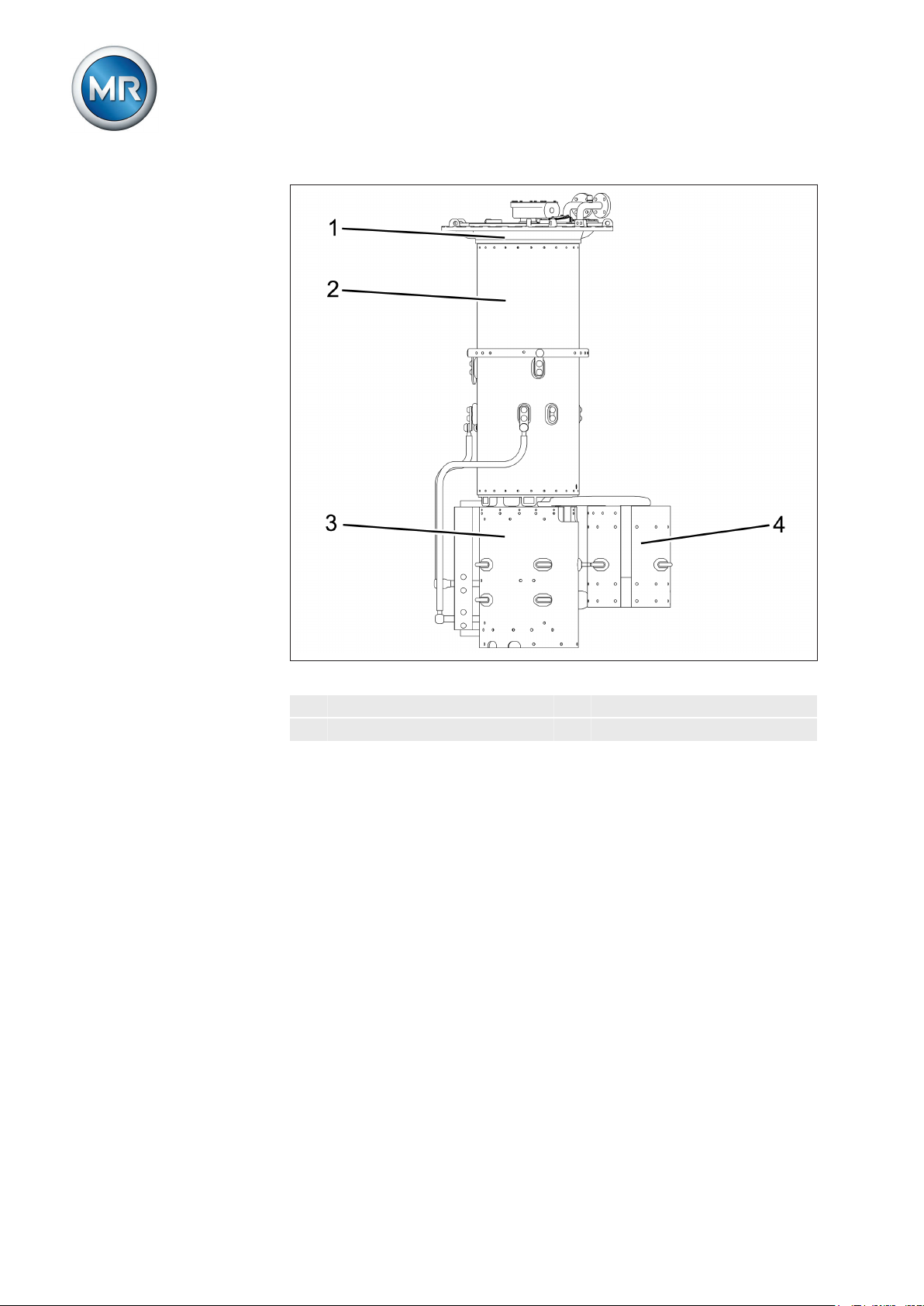
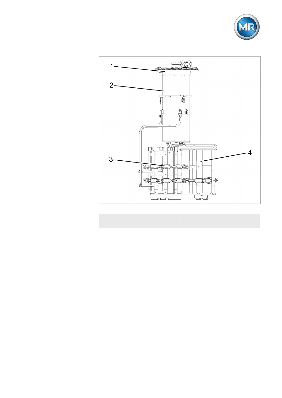
Setup/models
The on-load tap-changer consists of the on-load tap-changer head, oil compartment with built-in diverter switch insert and the tap selector mounted below (also available with change-over selector on request).
The design and designation of the most important on-load tap-changer components are shown in the installation drawings in the appendix.
Maschinenfabrik Reinhausen GmbH 201726 5293014/00 ENVACUTAP® VR I HD-Ex
Page 27

3 Product description
For the number of maximum operating positions of the on-load tap-changer,
refer to the Technical data.
Figure 4: VACUTAP® VRC/VRE
1 On-load tap-changer head 3 Tap selector
2 Oil compartment 4 Change-over selector
Maschinenfabrik Reinhausen GmbH 2017 275293014/00 EN VACUTAP® VR I HD-Ex
Page 28
3 Product description
Figure 5: VACUTAP® VRD/VRF
1 On-load tap-changer head 3 Tap selector
2 Oil compartment 4 Change-over selector
Maschinenfabrik Reinhausen GmbH 201728 5293014/00 ENVACUTAP® VR I HD-Ex
Page 29
3 Product description
3.2.2.1
Figure 6: VACUTAP® VRG
1 On-load tap-changer head 3 Tap selector
2 Oil compartment 4 Change-over selector
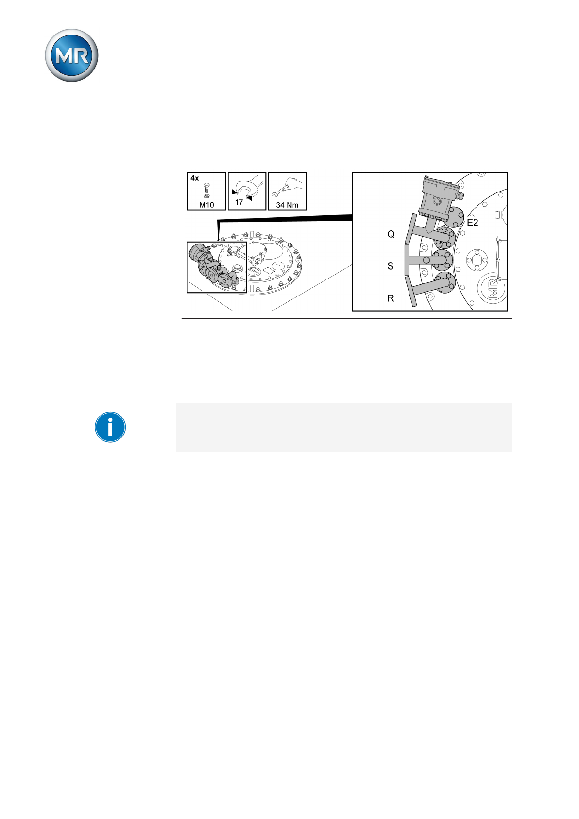
Pipe connections
The on-load tap-changer head features 4 pipe connections for different purposes.
Maschinenfabrik Reinhausen GmbH 2017 295293014/00 EN VACUTAP® VR I HD-Ex
Page 30
3 Product description
Depending on the order, some or all of these pipe connections are fitted with
pipe bends ex factory. All pipe bends without terminal box for the tap-change
supervisory control can be freely swiveled once the pressure ring is loosened.
Figure 7: Pipe connections with pipe bends
Pipe connection Q
Pipe connection Q is sealed off with a blank cover and, depending on the
on-load tap-changer type, is intended for the bushing of the tap-change supervisory device supplied as an option.
The functions of the R and Q pipe connections can be interchanged.
Pipe connection S
The pipe bend on pipe connection S features a vent screw and can be connected to a pipe that ends with a drain valve on the side of the transformer
tank at operating height. If the on-load tap-changer is fitted with an oil suction pipe, the on-load tap-changer can be completely emptied via pipe connection S.
Pipe connection R
Pipe connection R is provided for attachment of the protective relay and connection of the on-load tap-changer oil conservator and can be interchanged
with pipe connection Q.
Pipe connection E2
The pipe connection E2 is sealed off with a blank cover. It leads into the oil
tank of the transformer, directly under the on-load tap-changer head and can
be connected to a collective pipe for the Buchholz relay, if necessary. This
pipe connection serves a further purpose, namely to equalize the pressure
Maschinenfabrik Reinhausen GmbH 201730 5293014/00 ENVACUTAP® VR I HD-Ex
Page 31
3 Product description
between the transformer tank and oil compartment of the on-load tap-changer, which is necessary for drying, oil filling and transportation of the transformer.
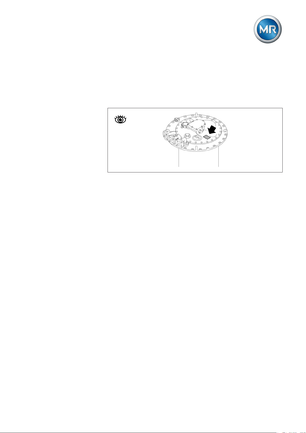
3.2.3
3.3
3.3.1
Name plate
The name plate is on the on-load tap-changer head cover.
Figure 8: Position of name plate
Drive shaft
Function description
The drive shaft is the mechanical connection between drive and on-load tapchanger head.
The bevel gear changes the direction from vertical to horizontal (see drawing
892916).
Accordingly, the vertical drive shaft has to be mounted between drive and
bevel gear and the horizontal drive shaft between bevel gear and on-load
tap-changer or de-energized tap-changer.
Maschinenfabrik Reinhausen GmbH 2017 315293014/00 EN VACUTAP® VR I HD-Ex
Page 32

3 Product description
The explosion-proof drive shaft consists of a square tube with insulator and
is coupled by two coupling brackets and one coupling bolt at both ends to
the drive or driven shaft end of the device to be connected.
Figure 9: Explosion-proof drive shaft with insulator
Maschinenfabrik Reinhausen GmbH 201732 5293014/00 ENVACUTAP® VR I HD-Ex
Page 33

3 Product description
3.3.2
Design/Model
The design of the explosion-proof drive shaft is described in this section.
Figure 10: Components of the explosion-proof drive shaft
1 Bevel gear 2 Hose clip
3 Screws 4 Telescopic protective tube
5 Coupling bracket 6 Insulator
7 Double coupling bracket 8 Square tube
9 Pin 10 Adapter ring
11 Protective cover 12 Hose clip
Maschinenfabrik Reinhausen GmbH 2017 335293014/00 EN VACUTAP® VR I HD-Ex
Page 34
3 Product description
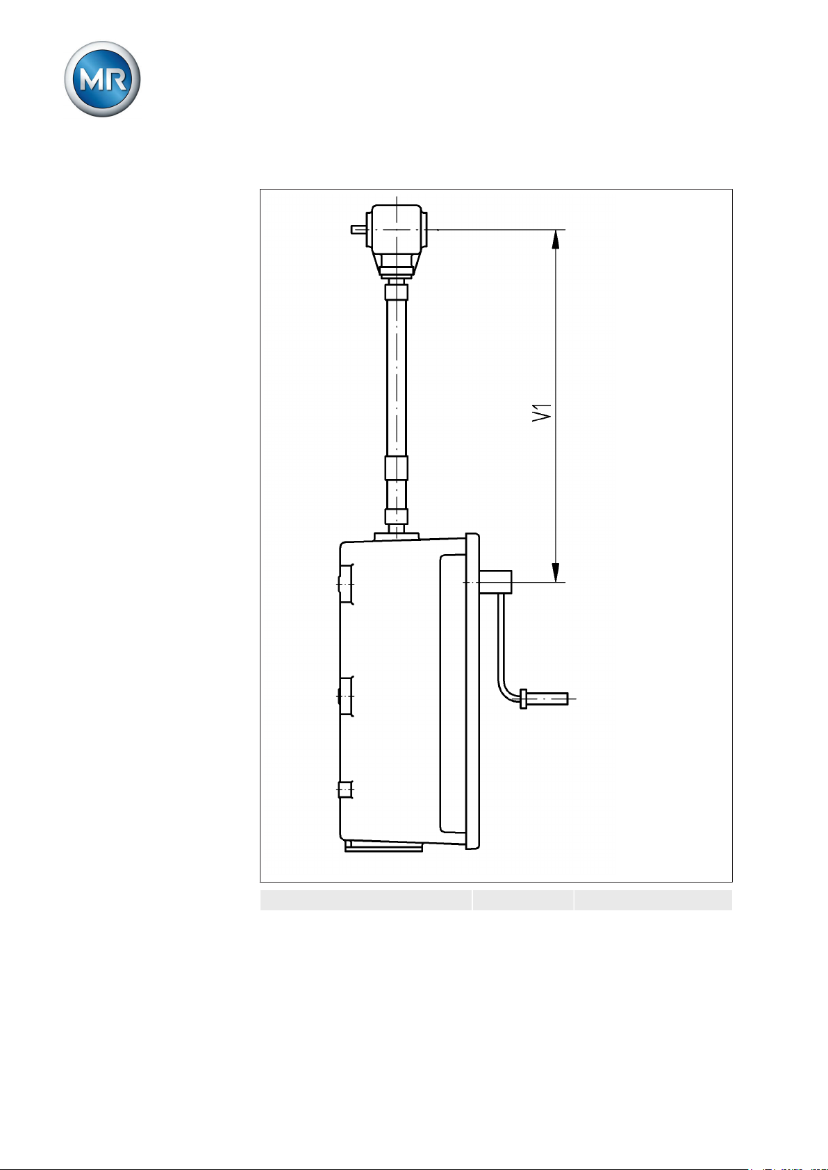
Configuration V 1 min Intermediate bearing
Maschinenfabrik Reinhausen GmbH 201734 5293014/00 ENVACUTAP® VR I HD-Ex
Page 35

3 Product description
3.3.3
Distance between middle of
hand crank and middle of bevel
gear
706 mm When the maximum
value of 2472 mm is
exceeded, it is necessary to use an intermediate bearing.
V 1 ≤ 2472 mm (without intermediate bearing)
V 1 > 2472 mm (with
intermediate bearing)
Identification plate
The identification plate is on the telescopic protective tube.
Figure 11: Position of the identification plate
Protective relay
3.4
3.4.1
Maschinenfabrik Reinhausen GmbH 2017 355293014/00 EN VACUTAP® VR I HD-Ex
Function description
The protective relay is used to protect the on-load tap-changer and the
transformer when a malfunction occurs in the diverter switch oil compartment
or selector switch oil compartment. It is tripped when the specified speed of
oil flow from the on-load tap-changer head to the oil conservator is exceeded
due to a fault. The flowing oil actuates the flap valve which tips over into position OFF. The contact in the dry-reed magnetic switch is thereby actuated,
the circuit breakers are tripped, and the transformer is de-energized.
Page 36
3 Product description
The protective relay is part of an on-load tap-changer filled with insulating
liquid and its properties conform to the applicable valid version of IEC publication 60214-1.
Diverter switch operations at rated switching capacity or at permissible overload will not cause the protective relay to trip.
The protective relay responds to oil flow, not to gas accumulated in the protective relay. It is not necessary to bleed the protective relay when filling the
transformer with oil. Gas accumulation in the protective relay is normal.
3.4.2
Setup/versions
Front view
Figure 12: RS 2001-Ex
1 Inspection window 2 Pressure equalization element
Rear view
Figure 13: RS 2001-Ex
1 Ground connection 2 Nameplate
Maschinenfabrik Reinhausen GmbH 201736 5293014/00 ENVACUTAP® VR I HD-Ex
Page 37
3 Product description
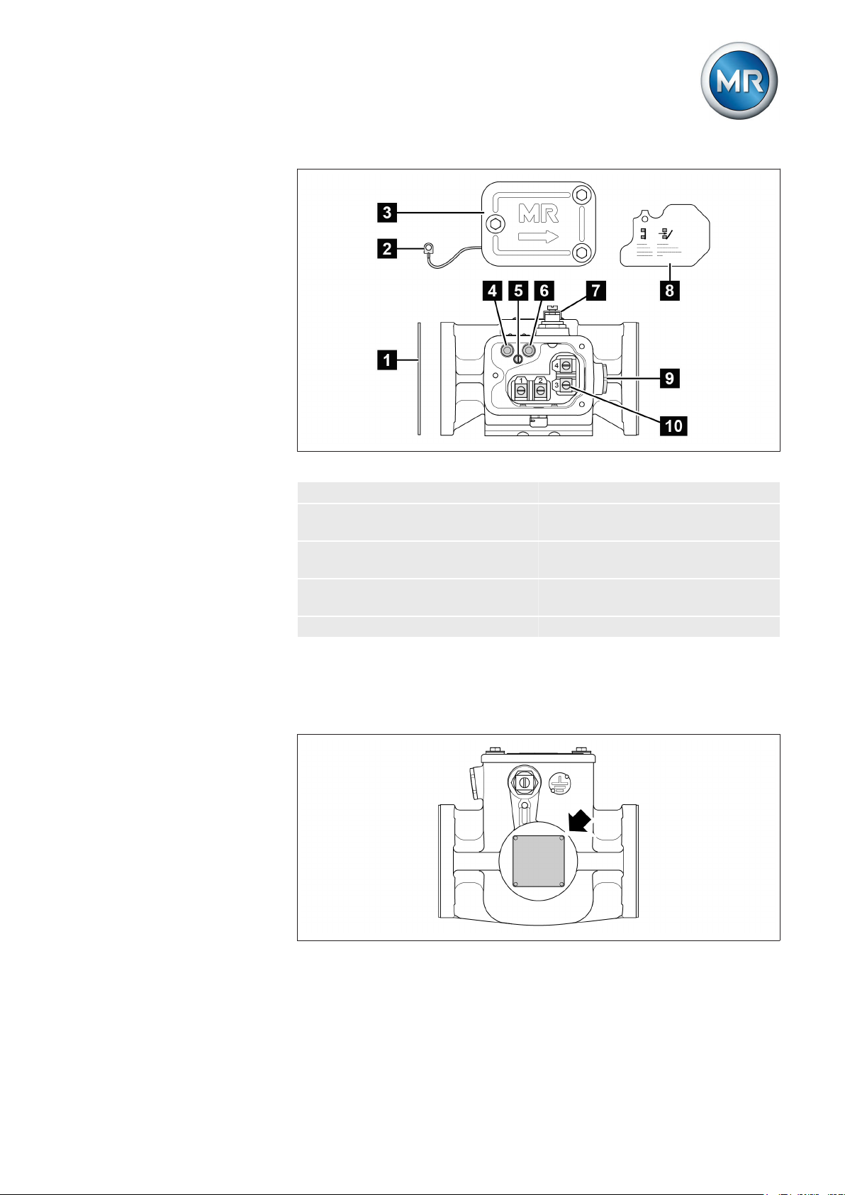
View from above
Figure 14: RS 2001-Ex
3.4.3
1 Gasket 2 Potential tie-in
3 Terminal box cover 4 OPERATION (reset) test but-
ton
5 Slotted head screw for poten-
6 OFF (test tripping) test button
tial tie-in
7 Protective conductor connec-
tion
8 Protective cover with picto-
gram for terminal assignment
9 Dummy plug 10 Connection terminal
Name plate
The name plate for the explosion-protected protective relay is on the rear of
the product.
Figure 15: Position of name plate
Maschinenfabrik Reinhausen GmbH 2017 375293014/00 EN VACUTAP® VR I HD-Ex
Page 38

4 Packaging, transport and storage
Packaging, transport and storage
4
Packaging
4.1
The products are sometimes supplied with a sealed packaging and sometimes also dried depending on what is required.
A sealed packaging surrounds the packaged goods on all sides with plastic
foil. Products that have also been dried are identified by a yellow label on the
sealed packaging.
The information in the following sections should be applied as appropriate.
4.1.1
NOTICE
4.1.2
Suitability
Property damage due to incorrectly stacked crates!
Stacking the crates incorrectly can lead to damage to the packaged goods!
► Only stack up to 2 equally sized crates on top of one another.
► Do not stack crates above a height of 1.5 m.
The packaging is suitable for undamaged and fully functional means of
transportation in compliance with local transportation laws and regulations.
The packaged goods are packed in a stable crate. This crate ensures that
when in the intended transportation position the packaged goods are stabilized to prevent impermissible changes in position, and that none of the parts
touch the loading surface of the means of transport or touch the ground after
unloading.
A sealed packaging surrounds the packaged goods on all sides with plastic
foil. The packaged goods are protected from humidity using a desiccant. The
plastic foil is bonded after the drying agent is added.
Markings
The packaging bears a signature with instructions for safe transport and correct storage. The following symbols apply to the shipment of non-hazardous
goods. Adherence to these symbols is mandatory.
Protect
against
moisture
Table 10: Shipping pictograms
Top Fragile Attach lifting
Center of
gear here
Maschinenfabrik Reinhausen GmbH 201738 5293014/00 ENVACUTAP® VR I HD-Ex
mass
Page 39

4 Packaging, transport and storage
Transportation, receipt and handling of shipments
4.2
WARNING
Danger of death and damage to property!
Danger of death and damage to property due to tipping or falling load.
► Transport crate when closed only.
► Do not remove the mounting material used in the crate during transport.
► Only trained and appointed persons may select the sling gear and se-
cure the load.
► Do not walk under the hanging load.
► Use means of transport and lifting gear with a sufficient carrying capaci-
ty in accordance with the weight stated on the delivery slip.
In addition to oscillation stress and shock stress, jolts must also be expected
during transportation. In order to prevent possible damage, avoid dropping,
tipping, knocking over and colliding with the product.
If a crate tips over, falls from a certain height (e.g. when slings tear) or experiences an unbroken fall, damage must be expected regardless of the
weight.
Every delivered shipment must be checked for the following by the recipient
before acceptance (acknowledgment of receipt):
▪ Completeness based on the delivery slip
▪ External damage of any type.
Visible damage
The checks must take place after unloading when the crate or transport container can be accessed from all sides.
If external transport damage is detected on receipt of the shipment, proceed
as follows:
▪ Immediately record the transport damage found in the shipping docu-
ments and have this countersigned by the carrier.
▪ In the event of severe damage, total loss or high damage costs, immedi-
ately notify the sales department at Maschinenfabrik Reinhausen and
the relevant insurance company.
▪ After identifying damage, do not modify the condition of the shipment
further and retain the packaging material until an inspection decision
has been made by the transport company or the insurance company.
▪ Record the details of the damage immediately onsite together with the
carrier involved. This is essential for any claim for damages!
▪ Photograph damage to packaging and packaged goods. This also ap-
plies to signs of corrosion on the packaged goods due to moisture inside
the packaging (rain, snow, condensation).
▪ NOTICE! Be absolutely sure to also check the sealed packaging. If the
sealed packaging is damaged, do not under any circumstances install or
commission the packaged goods. Either dry the dried packaged goods
again as per the operating instructions for the relevant on-load tap-
Maschinenfabrik Reinhausen GmbH 2017 395293014/00 EN VACUTAP® VR I HD-Ex
Page 40

4 Packaging, transport and storage
changer/de-energized tap-changer or contact Maschinenfabrik Reinhausen GmbH to agree on how to proceed with drying. If this is not done,
the packaged goods may be damaged.
▪ Name the damaged parts.
Hidden damage
4.3
When damages are not determined until unpacking after receipt of the shipment (hidden damage), proceed as follows:
▪ Make the party responsible for the damage liable as soon as possible by
telephone and in writing, and prepare a damage report.
▪ Observe the time periods applicable to such actions in the respective
country. Inquire about these in good time.
With hidden damage, it is very hard to make the transportation company (or
other responsible party) liable. Any insurance claims for such damages can
only be successful if relevant provisions are expressly included in the insurance terms and conditions.
Storage of shipments
Packaged goods dried by Maschinenfabrik Reinhausen
Upon receipt of the shipment, immediately remove the packaged goods
dried by Maschinenfabrik Reinhausen from the sealed packaging and store
air-tight in dry insulating oil until used if the packaged goods were not supplied in oil.
Non-dried packaged goods
Non-dried packaged goods but with a functional sealed packaging can be
stored outdoors when the following conditions are complied with.
When selecting and setting up the storage location, ensure the following:
▪ Protect stored goods against moisture (flooding, water from melting
snow and ice), dirt, pests such as rats, mice, termites and so on, and
against unauthorized access.
▪ Store the crates on timber beams and planks as a protection against ris-
ing damp and for better ventilation.
▪ Ensure sufficient carrying capacity of the ground.
▪ Keep entrance paths free.
▪ Check stored goods at regular intervals. Also take appropriate action af-
ter storms, heavy rain or snow and so on.
Protect the packaging foil from direct sunlight so that it does not disintegrate
under the influence of UV rays, which would cause the packaging to lose its
sealing function.
Maschinenfabrik Reinhausen GmbH 201740 5293014/00 ENVACUTAP® VR I HD-Ex
Page 41

4 Packaging, transport and storage
If the product is installed more than 6 months after delivery, suitable measures must be taken without delay. The following measures can be used:
▪ Correctly regenerate the drying agent and restore the sealed packaging.
▪ Unpack the packed goods and store in suitable storage space (well ven-
Unpacking shipments and checking for transportation
4.4
damages
▪ NOTICE! Transport the packaged crate to the place where installation
▪ WARNING! When unpacking, check the condition of the packaged
▪ Check completeness of supplementary parts on the basis of the delivery
tilated, as dust-free as possible, humidity < 50 % where possible).
will take place. Do not open the sealed packaging until just before installation. If this is not done, damage to the packaged goods may occur due
to ineffectively sealed packaging.
goods.Secure packaged goods in an upright crate from tipping out. If
this is not done, the packaged goods may be damaged and serious injuries may result.
slip.
Maschinenfabrik Reinhausen GmbH 2017 415293014/00 EN VACUTAP® VR I HD-Ex
Page 42

Mounting
5
5 Mounting
WARNING
Risk of crushing from moving parts!
When the on-load tap-changer undertakes a tap-change operation, components move on the selector, change-over selector, and potential connection
unit, some of which are freely accessible. Reaching into the selector,
change-over selector or potential connection unit during a tap-change operation may result in serious injuries.
► Keep at a safe distance of at least 1 m during tap-change operations.
► Do not reach into the selector, change-over selector, or potential con-
nection unit during tap-change operations.
► Do not switch the on-load tap-changer when working on the selector,
change-over selector, or potential connection unit.
This chapter describes how to install the on-load tap-changer in a transformer and how to dry it, and also how to mount the protective devices and drive
components.
Preparatory work
5.1
Perform the work stated below before installing the on-load tap-changer in
the transformer.
Maschinenfabrik Reinhausen GmbH 201742 5293014/00 ENVACUTAP® VR I HD-Ex
Page 43

5 Mounting
5.1.1
Fitting mounting flange on transformer cover
A mounting flange is required for fitting the on-load tap-changer head on the
transformer cover. This can be supplied as an option or can be produced by
the customer. Mounting flanges made by the customer must comply with the
installation drawings in the appendix.
► NOTICE! Fit mounting flange on transformer cover (pressure tight).En-
sure that the sealing face makes complete contact and is not damaged.
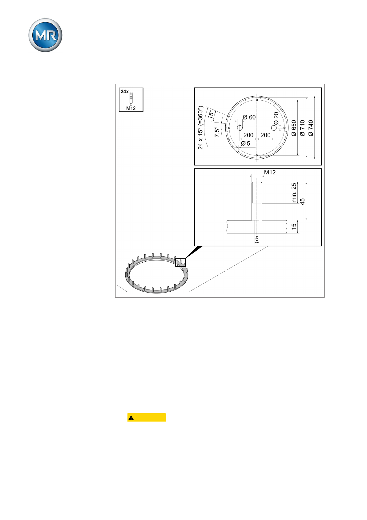
5.1.2
Figure 16: Mounting flange
Fitting stud bolts on mounting flange
To attach the stud bolts to the mounting flange, use a tracing template. This
can be provided upon request free of charge for the initial installation of the
on-load tap-changer.
1. Place tracing template on mounting flange and use the four markings to
align.
Maschinenfabrik Reinhausen GmbH 2017 435293014/00 EN VACUTAP® VR I HD-Ex
Page 44
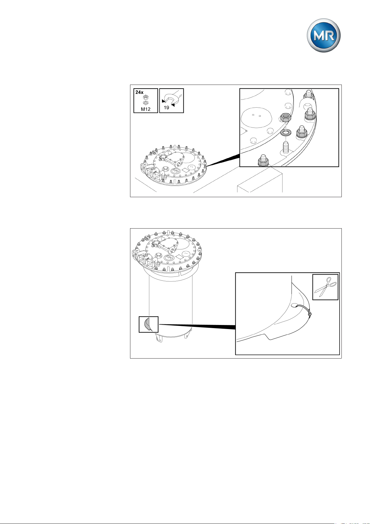
2. Fit stud bolts on mounting flange.
5 Mounting
5.2
5.2.1
5.2.1.1
Figure 17: Tracing template, stud bolts
Installing the standard version on-load tap-changer in the transformer
Perform the work stated below in order to install the on-load tap-changer in
the transformer (standard version).
Fastening on-load tap-changer to transformer cover
This chapter describes how to fasten the on-load tap-changer to the transformer cover.
Fastening oil compartment on transformer cover
1. CAUTION! Prior to installing the on-load tap-changer, remove the
red-colored packaging and transport material from the on-load tapchanger.
Maschinenfabrik Reinhausen GmbH 201744 5293014/00 ENVACUTAP® VR I HD-Ex
Page 45

5 Mounting
2. CAUTION! Place the oil compartment on a level surface and secure
it against tipping. An unstably positioned oil compartment may tip over,
resulting in serious injuries and damage.
3. Clean sealing surfaces on mounting flange and on-load tap-changer
head, place oil-resistant gasket on mounting flange.
Figure 18: Sealing surfaces, seal
Maschinenfabrik Reinhausen GmbH 2017 455293014/00 EN VACUTAP® VR I HD-Ex
Page 46

5 Mounting
4. Lift the oil compartment by hooking up the on-load tap-changer head
and carefully lower the oil compartment into the cover opening of the
transformer.
Figure 19: Oil compartment
5. Check that the on-load tap-changer head is mounted in the position
specified by the design.
Maschinenfabrik Reinhausen GmbH 201746 5293014/00 ENVACUTAP® VR I HD-Ex
Page 47
5 Mounting
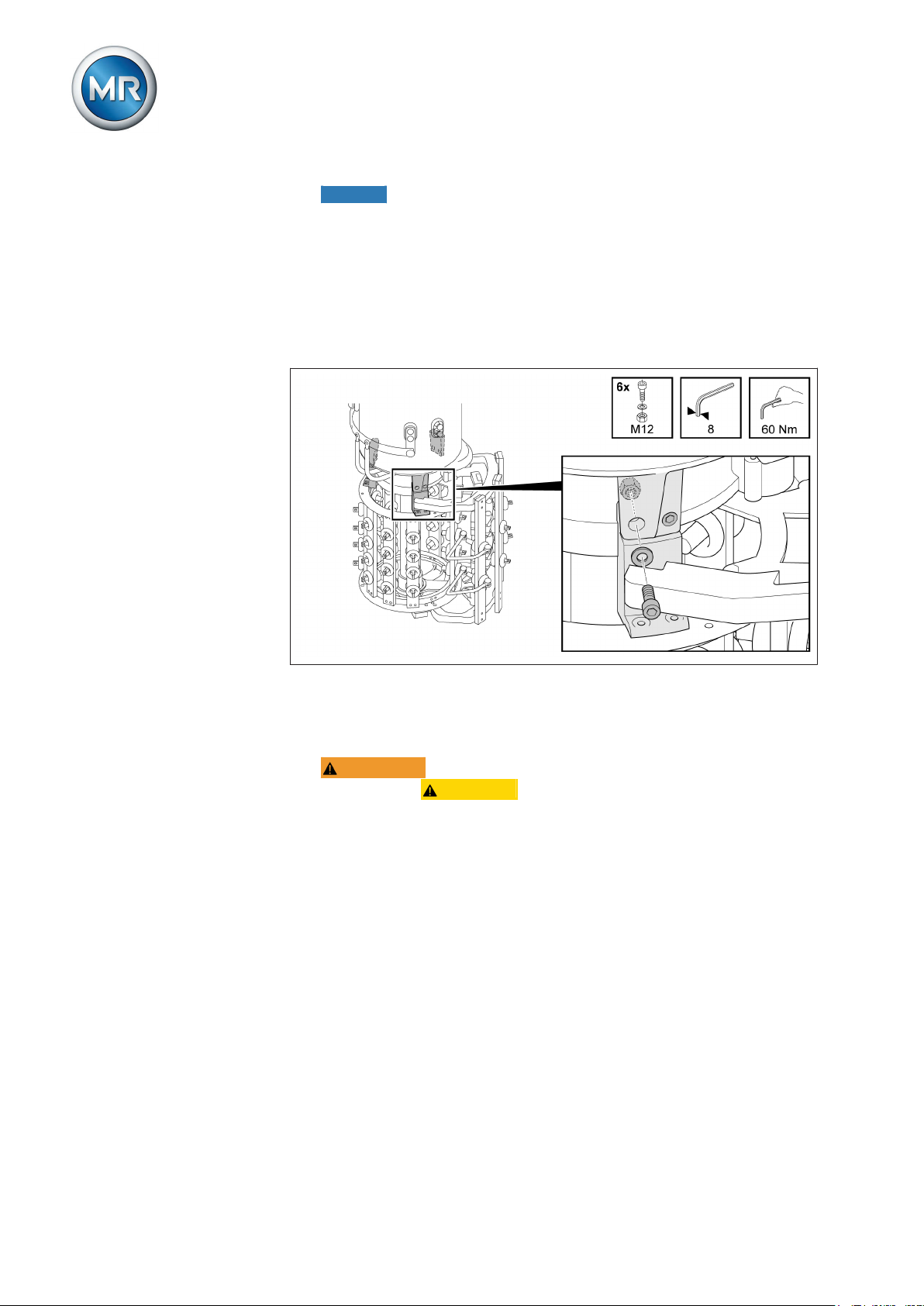
6. Screw on-load tap-changer head to mounting flange.
Figure 20: On-load tap-changer head with mounting flange
7. Remove the blocking device from the coupling of the oil compartment
base.
Figure 21: VACUTAP® VRC/VRE, blocking strip
Maschinenfabrik Reinhausen GmbH 2017 475293014/00 EN VACUTAP® VR I HD-Ex
Page 48

5 Mounting
Figure 22: VACUTAP® VRD/VRF, blocking plate and shackle
Figure 23: VACUTAP® VRG, blocking plate and shackle
Maschinenfabrik Reinhausen GmbH 201748 5293014/00 ENVACUTAP® VR I HD-Ex
Page 49

5 Mounting
5.2.1.2
Securing tap selector on oil compartment of the on-load tap-changer VRC/VRE
1. WARNING! Place the selector on a level surface and secure it
against tipping CAUTION! . An unstably positioned selector may tip,
resulting in injuries and property damage.
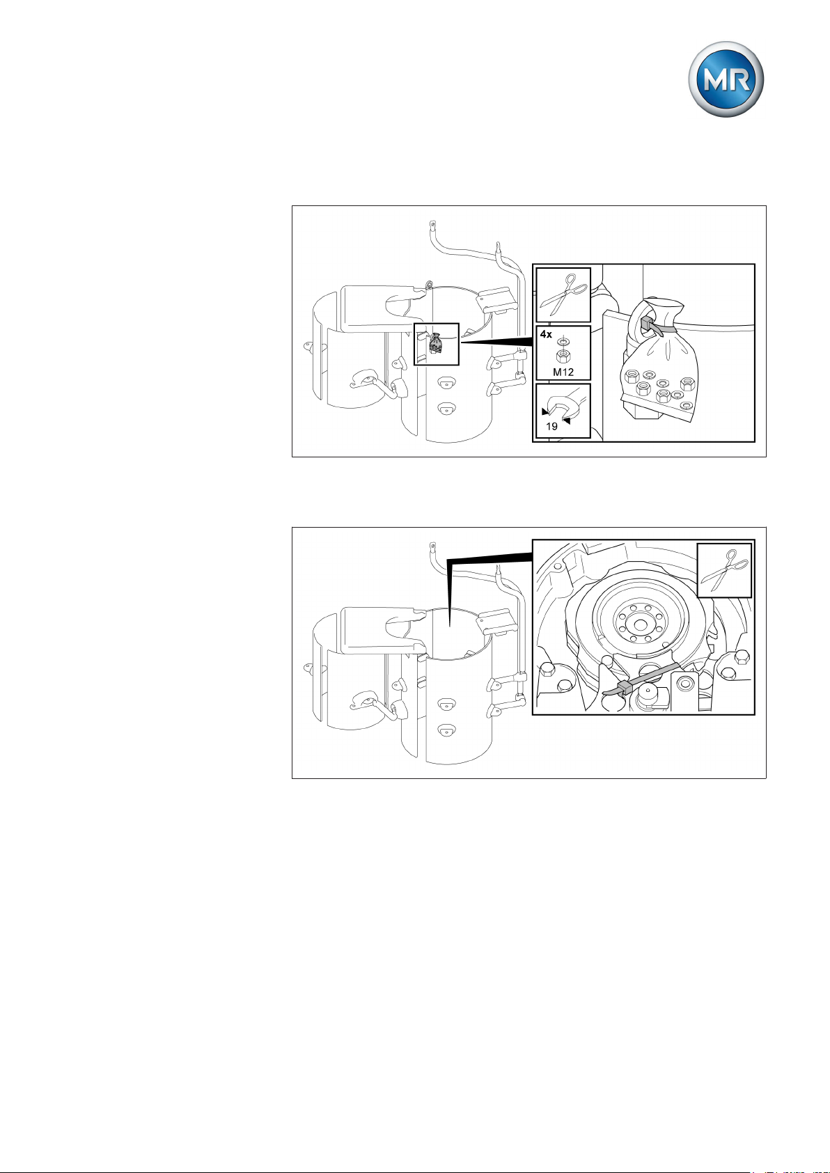
2. Remove plastic bag with fastening materials from the selector and keep
them ready.
Figure 24: Plastic bag with fastening materials
3. Remove the blocking strip from the selector coupling. Once the blocking
strip is removed, the selector coupling must no longer be turned.
Figure 25: Blocking strip
4. Place the selector on the lifting device. The weight of the selector is a
maximum of 165 kg.
Maschinenfabrik Reinhausen GmbH 2017 495293014/00 EN VACUTAP® VR I HD-Ex
Page 50
5 Mounting
5. NOTICE! Carefully lift selector below the oil compartment, ensuring that
the tap-selector connecting leads are free when lifting the selector on
the oil compartment and do not touch the compartment. Failure to comply with this instruction may result in the tap-selector connecting leads
being damaged.
6. Align the position of both coupling parts and attachment points on the oil
compartment and the selector with one another. The correct position of
the two coupling parts is shown in the adjustment plans in the appendix.
7. Screw selector onto oil compartment.
5.2.1.3
Figure 26: Selector with oil compartment
Securing tap selector on oil compartment of the on-load tap-changer VRC/VRE
1. WARNING! Place the selector on a level surface and secure it
against tipping CAUTION! . An unstably positioned selector may tip,
resulting in injuries and property damage.
Maschinenfabrik Reinhausen GmbH 201750 5293014/00 ENVACUTAP® VR I HD-Ex
Page 51
5 Mounting
2. Remove plastic bag with fastening materials from the selector and keep
them ready.
Figure 27: Plastic bag with fastening materials
3. Remove the blocking strip from the selector coupling. Once the blocking
strip is removed, the selector coupling must no longer be turned.
Figure 28: Blocking strip
4. Place the selector on the lifting device. The weight of the selector is a
maximum of 270 kg.
Maschinenfabrik Reinhausen GmbH 2017 515293014/00 EN VACUTAP® VR I HD-Ex
Page 52

5 Mounting
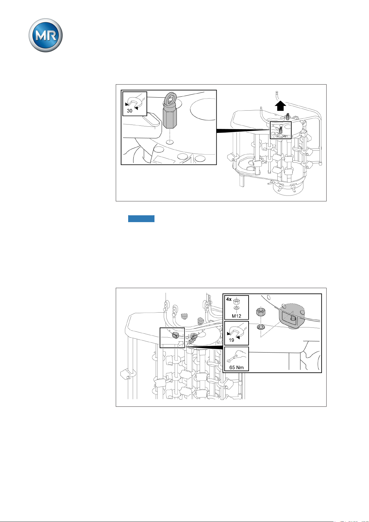
5. Remove the ring nuts from the selector.
Figure 29: Ring nut
6. NOTICE! Carefully lift selector below the oil compartment, ensuring that
the tap-selector connecting leads are free when lifting the selector on
the oil compartment and do not touch the compartment. Failure to comply with this instruction may result in the tap-selector connecting leads
being damaged.
7. Align the position of both coupling parts and attachment points on the oil
compartment and the selector with one another. The correct position of
the two coupling parts is shown in the adjustment plans in the appendix.
8. Screw selector onto oil compartment.
Figure 30: Selector with oil compartment
9. Remove the wooden support on the underside of the change-over selector.
Maschinenfabrik Reinhausen GmbH 201752 5293014/00 ENVACUTAP® VR I HD-Ex
Page 53

5 Mounting
5.2.1.4
Securing tap selector on oil compartment of the on-load tap-changer VRG
1. WARNING! Place the selector on a level surface and secure it
against tipping CAUTION! . An unstably positioned selector may tip,
resulting in injuries and property damage.
2. Remove plastic bag with fastening materials from the selector and keep
them ready.
Figure 31: Plastic bag with fastening materials
3. Remove the blocking strip from the selector coupling. Once the blocking
strip is removed, the selector coupling must no longer be turned.
Figure 32: Blocking strip
4. Place the selector on the lifting device. The weight of the selector is a
maximum of 465 kg.
Maschinenfabrik Reinhausen GmbH 2017 535293014/00 EN VACUTAP® VR I HD-Ex
Page 54
5. Remove the ring nuts from the selector.
Figure 33: Ring nut
5 Mounting
6. NOTICE! Carefully lift selector below the oil compartment, ensuring that
the tap-selector connecting leads are free when lifting the selector on
the oil compartment and do not touch the compartment. Failure to comply with this instruction may result in the tap-selector connecting leads
being damaged.
7. Align the position of both coupling parts and attachment points on the oil
compartment and the selector with one another. The correct position of
the two coupling parts is shown in the adjustment plans in the appendix.
8. Screw selector onto oil compartment.
Figure 34: Selector with oil compartment
Maschinenfabrik Reinhausen GmbH 201754 5293014/00 ENVACUTAP® VR I HD-Ex
Page 55

5 Mounting
5.2.1.5
Connecting tap-selector connecting leads
Proceed as follows to connect the tap-selector connecting leads:
1. NOTICE! Carefully screw tap-selector connecting leads to connecting
piece or ring segment. Comply with specified tightening torque and secure screw connection. Failure to do so may result in damage to the onload tap-changer and transformer.
2. Attach screening caps to screw connection.
Figure 35: Connecting piece
Figure 36: Ring segment
Maschinenfabrik Reinhausen GmbH 2017 555293014/00 EN VACUTAP® VR I HD-Ex
Page 56

5 Mounting
5.2.2
Connecting the tap winding and on-load tap-changer take-off lead
NOTICE
5.2.2.1
Damage to the on-load tap-changer!
Connecting leads which place mechanical strain on the on-load tap-changer
will damage the on-load tap-changer!
► Establish connections carefully.
► Do not twist connection contacts.
► Connect connecting leads without warping or deforming.
► If necessary, use an expansion loop for connecting leads.
► Fit screening caps provided to screw connections.
The tap winding and on-load tap-changer take-off lead must be connected in
accordance with the connection diagram included with the delivery.
Tap selector connection contacts VRC/VRE
The selector connection contacts are indicated on the selector bars, have
crimped ends and a through-hole for M10 screws to allow the tap-selector
connecting leads to be connected with cable shoes.
The screening caps are supplied separately.
In this case a locking washer must be placed below each screening cap. The
M10 connection screws, the nuts, and locking washers are not included in
the scope of delivery.
The through-holes of the connection contacts are either horizontal or vertical, depending on the on-load tap-changer version.
Figure 37: Selector connection contacts
Maschinenfabrik Reinhausen GmbH 201756 5293014/00 ENVACUTAP® VR I HD-Ex
Page 57

5 Mounting
Figure 38: Screening caps
NOTICE
5.2.2.2
Selector connection contacts for multiple coarse change-over selector
In the case of multiple coarse change-over selectors, take care when routing
the cables for connecting to the selector connection contacts and the multiple coarse change-over selector connection contacts. These cables should
be as far away as possible from neighboring connection contacts.
► The selector connection contacts that face both multiple coarse change-
over selector columns must have at least 3 mm of paper insulation to
ensure dielectric strength.
Damage to the on-load tap-changer!
Tap-winding connecting leads situated too closely to the change-over selector's moving parts block the change-over selector and therefore result in onload tap-changer damage!
► Tap-winding connecting leads in the area of the change-over selector
have to be routed such that they are at a sufficient distance from the
change-over selector's moving parts.
Maschinenfabrik Reinhausen GmbH 2017 575293014/00 EN VACUTAP® VR I HD-Ex
Page 58
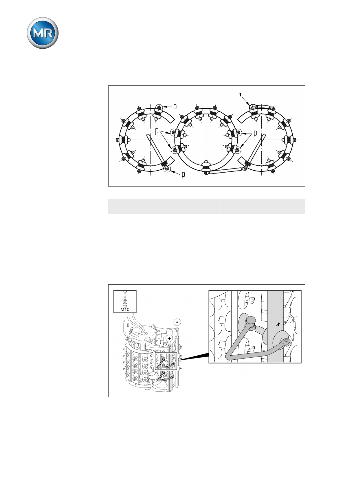
5 Mounting
In this regard, please also pay attention to the dimensional drawing on which
the order is based.
Figure 39: Paper insulation
1 Connection from MR already
p Connections to be insulated
has 3 mm of paper insulation
5.2.2.3
Change-over selector connection contacts for reversing change-over selector connection VRC/VRE
The (+) and (-) change-over selector connection contacts are designed as
connecting lugs with through-holes for M10 screws for reversing changeover selector connection.
Connection contact K is designed as an extended fine tap selector connection contact (also with through-hole for M10 screws).
Figure 40: Change-over selector connection contacts for reversing change-over selector connection
Maschinenfabrik Reinhausen GmbH 201758 5293014/00 ENVACUTAP® VR I HD-Ex
Page 59

5 Mounting
NOTICE
Damage to the on-load tap-changer!
Tap-winding connecting leads situated too closely to the change-over selector's moving parts block the change-over selector and therefore result in onload tap-changer damage!
► Tap-winding connecting leads in the area of the change-over selector
have to be routed such that they are at a sufficient distance from the
change-over selector's moving parts.
Figure 41: Change-over selector connection contacts for reversing change-over selector connection (top view)
Maschinenfabrik Reinhausen GmbH 2017 595293014/00 EN VACUTAP® VR I HD-Ex
Page 60
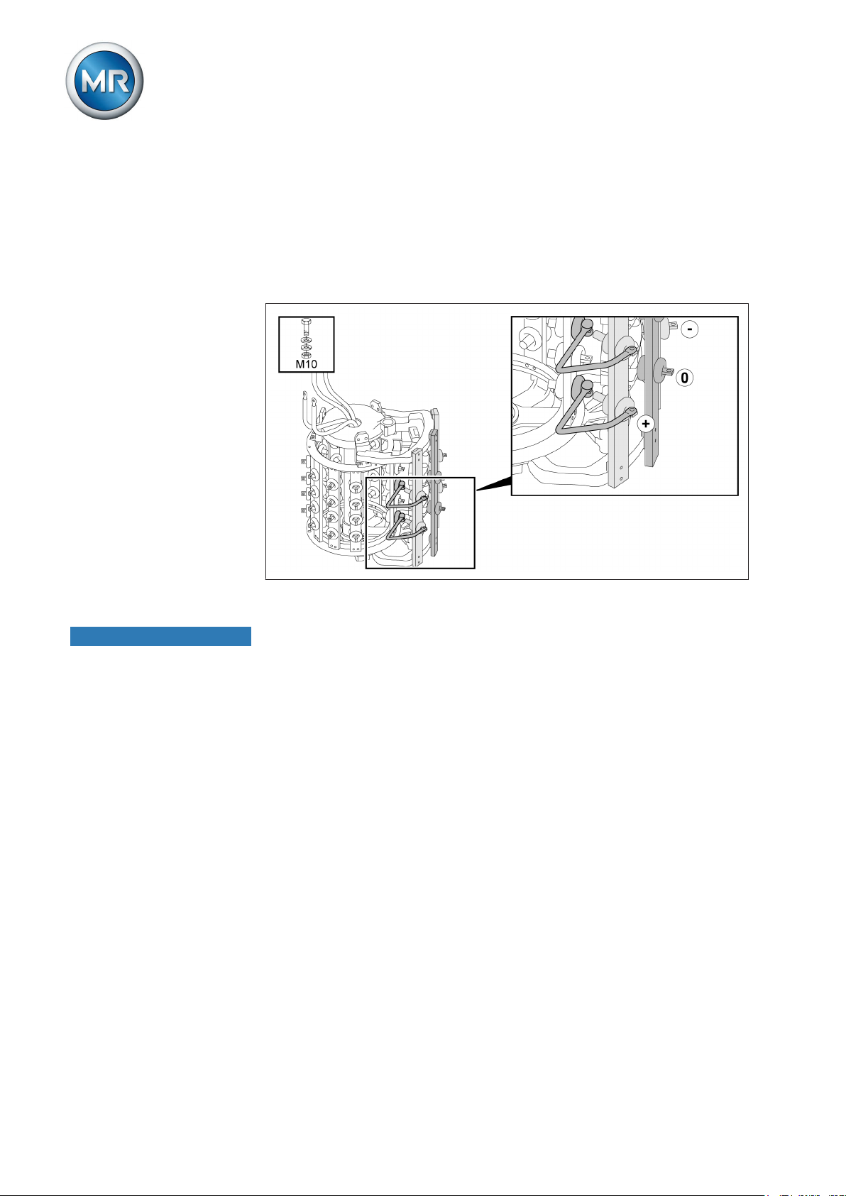
5 Mounting
5.2.2.4
Change-over selector connection contacts for coarse tap selector connection VRC/VRE
With coarse tap selector connection, the (+) and (-) change-over selector
connection contacts are secured to the respective laminated paper bars of
the coarse change-over selector. Their external appearance is identical to
the fine tap selector contacts (through-hole for M10 screws, always in vertical position).
NOTICE
Figure 42: Change-over selector connection contacts for coarse tap selector connection
Damage to the on-load tap-changer!
Tap-winding connecting leads situated too closely to the change-over selector's moving parts block the change-over selector and therefore result in onload tap-changer damage!
► Tap-winding connecting leads in the area of the change-over selector
have to be routed such that they are at a sufficient distance from the
change-over selector's moving parts.
Maschinenfabrik Reinhausen GmbH 201760 5293014/00 ENVACUTAP® VR I HD-Ex
Page 61

5 Mounting
Figure 43: Change-over selector connection contacts for coarse tap selector connection (top view)
5.2.2.5
Selector connection contacts VRD/VRF
The selector connection contacts have a through-hole for M12 screws. The
screening caps are supplied separately.
Figure 44: Selector connection contacts
Maschinenfabrik Reinhausen GmbH 2017 615293014/00 EN VACUTAP® VR I HD-Ex
Page 62

5 Mounting
5.2.2.6
5.2.2.7
Change-over selector connection contacts for reversing change-over selector connection VRD/VRF
The (+) and (-) change-over selector connection contacts are designed like
fine tap selector connection contacts for reversing change-over selector connections. The change-over selector connection contacts (0) are produced as
terminal lugs of the crimped connecting lead (=0/K) with a through-hole for
M12 screws.
Figure 45: Change-over selector connection contacts for reversing change-over selector connection
Change-over selector connection contacts for coarse tap selector connection VRD/VRF
5.2.2.8
For coarse tap selector connection, the (0) and (–) change-over selector
connection contacts are designed like the fine tap selector connection contacts. The change-over selector connection contacts (+) are produced as terminal lugs of the crimped connecting lead (+/K) with a through-hole for M12
screws.
Figure 46: Change-over selector connection contacts for coarse tap selector connection
Parallel bridges for VRF I 1601/1801
Bridges for connecting the connection contacts of the fine tap selector and
change-over selector in parallel in accordance with drawing 786919 will be
supplied.
Maschinenfabrik Reinhausen GmbH 201762 5293014/00 ENVACUTAP® VR I HD-Ex
Page 63

5 Mounting
5.2.2.9
Fine-tap-selector and change-over-selector connection contacts VRG
The selector connection contacts are indicated on the selector bars. The
connection is made at the thread stud of the selector connection contact via
cable shoes and locknuts.
Every connection point must be covered by a screening cap. The screening
caps are designed for lateral connection with a straight cable shoe or for
front connection with an angled cable shoe.
Figure 47: Tap selector connection contacts and change-over selector connection
contacts
Each screening cap is attached with a steel angle piece and 2 screws. The
connection is secured by centre-punching at the perimeter of the screw
head. The distance between the screening caps and adjacent tap-selector
connecting leads must be at least 25 mm!
Figure 48: Screening caps
Maschinenfabrik Reinhausen GmbH 2017 635293014/00 EN VACUTAP® VR I HD-Ex
Page 64

5 Mounting
5.2.2.10
5.2.2.11
Parallel bridges for VRG I 1601/1801
Bridges for connecting the connection contacts of the fine tap selector and
change-over selector in parallel in accordance with drawing 786920 will be
supplied.
Connecting on-load tap-changer take-off lead
There are through-holes 13 mm in diameter at several points in the take-off
ring of the oil compartment for connecting the on-load tap-changer take-off
lead.
Proceed as follows to connect the on-load tap-changer take-off lead:
1. Connect the on-load tap-changer take-off lead to any through-hole on
the take-off ring of the oil compartment.
2. Secure screw connection.
5.2.3
Figure 49: Take-off ring on oil compartment
Carrying out transformer ratio test before drying
To perform the transformer ratio test, proceed as follows:
Maschinenfabrik Reinhausen GmbH 201764 5293014/00 ENVACUTAP® VR I HD-Ex
Page 65

5 Mounting
NOTICE
Damage to property!
Damage to on-load tap-changer due to transformer ratio test being incorrectly performed!
► Do not perform more than 250 tap-change operations on the on-load
tap-changer. If more than 250 tap-change operations are performed,
completely fill oil compartment with insulating oil and lubricate sliding
surfaces of contacts on selector and selector gear with insulating oil.
► Only switch the on-load tap-changer from one operating position to the
next via the upper gear unit. You can use a short tube (diameter
25 mm) with screwed-in coupling bolt (diameter 12 mm) with a hand
wheel or crank for this. When using a drill, do not exceed a maximum
speed of 250 rpm.
► Always check the operating position reached through the inspection
window in the on-load tap-changer head cover. Never overshoot the
end positions, which are indicated in the connection diagram supplied
with the delivery.
► For multiple-column applications with a shared drive, link all on-load
tap-changer heads to one another with the horizontal drive shaft part.
1. Switch on-load tap-changer into the desired operating position. The
diverter switch operation can be heard distinctly.
When actuating the change-over selector a higher torque is required.
5.2.4
2. NOTICE! After operating the diverter switch, continue to crank 2.5 revolutions in the same direction on the drive shaft of the upper gear unit in
order to correctly end the tap-change operation. An incomplete tapchange operation may damage the on-load tap-changer!
3. Carry out the transformer ratio test.
4. Repeat the transformer ratio test in all operating positions.
5. Once the transformer ratio test is complete, return on-load tap-changer
to its adjustment position (see supplied connection diagram of the onload tap-changer).
After the transformer ratio test, open the kerosene drain plug in the oil compartment if the on-load tap-changer is to be dried with kerosene in the transformer tank. After drying, the diverter switch insert must be removed, the
kerosene drain plug in the oil compartment closed and the diverter switch
insert refitted.
Measuring DC resistance on transformer
Note the measurement scenarios listed below and the associated maximum
measurement currents when measuring DC resistance on the transformer.
Maschinenfabrik Reinhausen GmbH 2017 655293014/00 EN VACUTAP® VR I HD-Ex
Page 66

5 Mounting
The measurement DC current is normally restricted to 10 % of the rated current of the measured transformer winding in order to prevent the winding
from overheating.
5.2.5
NOTICE
Measure the DC resistance in the various on-load tap-changer operating positions. You need to distinguish here whether the measurement current is interrupted when changing operating position or not.
Without interruption
in measurement current
Oil compartment emp-tyMaximum 10 A DC Maximum 50 A DC
Oil compartment filled
with insulating oil
Table 11: Maximum permitted measurement currents when measuring DC resistance
on transformer
Maximum 50 A DC Maximum 50 A DC
With interruption
(measurement current = 0 A before
change in operating
position)
Drying on-load tap-changer in autoclave
Property damage!
Damage to on-load tap-changer resulting from insufficient dielectric strength
of the mineral insulating oil caused by moisture in the oil compartment.
► Within 10 hours of drying, seal off oil compartment with on-load tap-
changer head cover.
5.2.5.1
Dry on-load tap-changer using the following instructions to ensure the dielectric values assured by MR on the on-load tap-changer.
If drying in an autoclave, the following methods are possible:
▪ Vacuum-drying
▪ Vapor-phase drying
Vacuum-drying in the autoclave
Before starting vacuum-drying in the autoclave, you must remove the onload tap-changer head cover and on-load tap-changer accessories:
1. NOTICE! Remove the on-load tap-changer head cover (24 screws M10/
wrench size 17 with safety elements) and store it outside the autoclave.
If this is not done, the on-load tap-changer head cover may be damaged.
2. NOTICE! Remove on-load tap-changer accessories and store outside
autoclave: motor-drive unit, drive shaft, protective relay, bevel gear,
temperature sensor. If this is not done, the on-load tap-changer accessories may be damaged.
Maschinenfabrik Reinhausen GmbH 201766 5293014/00 ENVACUTAP® VR I HD-Ex
Page 67
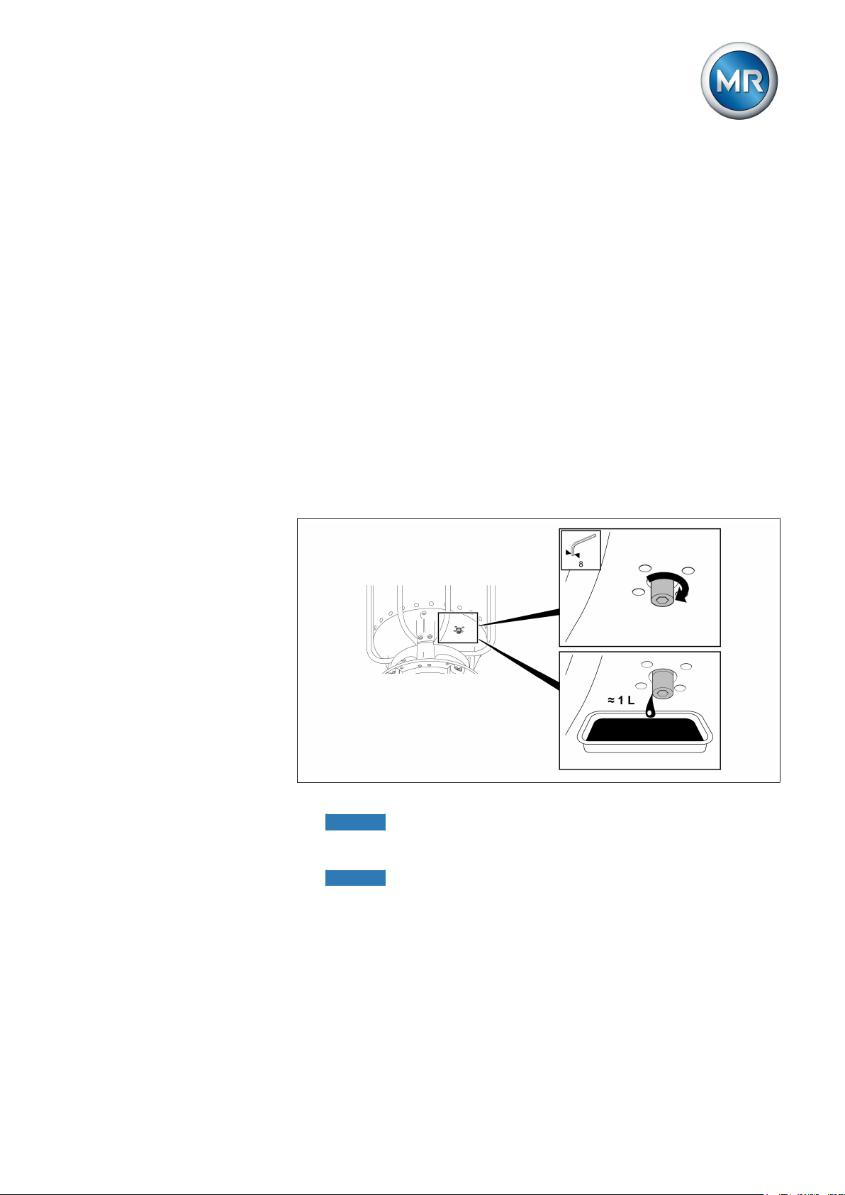
5 Mounting
Vacuum-drying in the autoclave
1. Heat up the on-load tap-changer in air at atmospheric pressure with a
temperature increase of about 10 °C/h to a final temperature of maximum 110 °C.
2. Pre-dry the on-load tap-changer in circulating air at a max. temperature
of 110 °C for a period of 20 hours.
3. Vacuum dry on-load tap-changer at between 105 °C and maximum 125
°C for at least 50 hours.
4. Residual pressure of no more than 10-3 bar.
5.2.5.2
Vapor-phase drying in the autoclave
For vapor-phase drying in the autoclave, you must open the kerosene drain
plug in the oil compartment base before drying so that the kerosene condensate can drain from the oil compartment.
1. Unscrew kerosene drain plug in base of oil compartment counter-clockwise. The kerosene drain plug cannot be unscrewed all the way.
Figure 50: Kerosene drain plug
2. NOTICE! Remove the on-load tap-changer head cover (24 screws M10/
wrench size 17 with locking washers) and store it outside the autoclave.
Otherwise, the on-load tap-changer head cover may be damaged.
3. NOTICE! Remove on-load tap-changer accessories and store outside
autoclave: motor-drive unit, drive shaft, protective relay, bevel gear,
temperature sensor. Otherwise, the on-load tap-changer accessories
may be damaged.
Vapor-phase drying in the autoclave
1. Supply kerosene vapor at a temperature of around 90 °C. Keep this
temperature constant for 3 to 4 hours.
Maschinenfabrik Reinhausen GmbH 2017 675293014/00 EN VACUTAP® VR I HD-Ex
Page 68

5 Mounting
2. Increase the kerosene vapor temperature by approx. 10 °C/hour to the
desired final temperature of max. 125 °C at the on-load tap-changer.
3. Vacuum dry on-load tap-changer at between 105 °C and maximum 125
°C for at least 50 hours.
4. Residual pressure of no more than 10-3 bar.
► NOTICE! Close kerosene drain plug clockwise (tightening torque 20
Nm). An open kerosene drain plug leads to oil escaping from the oil
compartment and therefore to damage to the on-load tap-changer and
transformer.
5.2.6
NOTICE
5.2.6.1
Drying on-load tap-changer in transformer tank
Property damage!
Damage to on-load tap-changer resulting from insufficient dielectric strength
of the mineral insulating oil caused by moisture in the oil compartment.
► Within 10 hours of drying, seal off oil compartment with on-load tap-
changer head cover.
Dry on-load tap-changer using the following instructions to ensure the dielectric values assured by MR on the on-load tap-changer.
If you want to dry the on-load tap-changer in the transformer tank, first complete transformer assembly and then undertake drying.
If drying in the transformer tank, the following methods are possible:
▪ Vacuum-drying
▪ Vapor-phase drying
Vacuum-drying in the transformer tank
To vacuum dry the on-load tap-changer in the transformer tank, proceed as
follows.
The on-load tap-changer head cover remains closed during the entire drying
process.
1. Establish a connecting lead either between connections E2 and Q or
connections E2 and R on the on-load tap-changer head.
Maschinenfabrik Reinhausen GmbH 201768 5293014/00 ENVACUTAP® VR I HD-Ex
Page 69
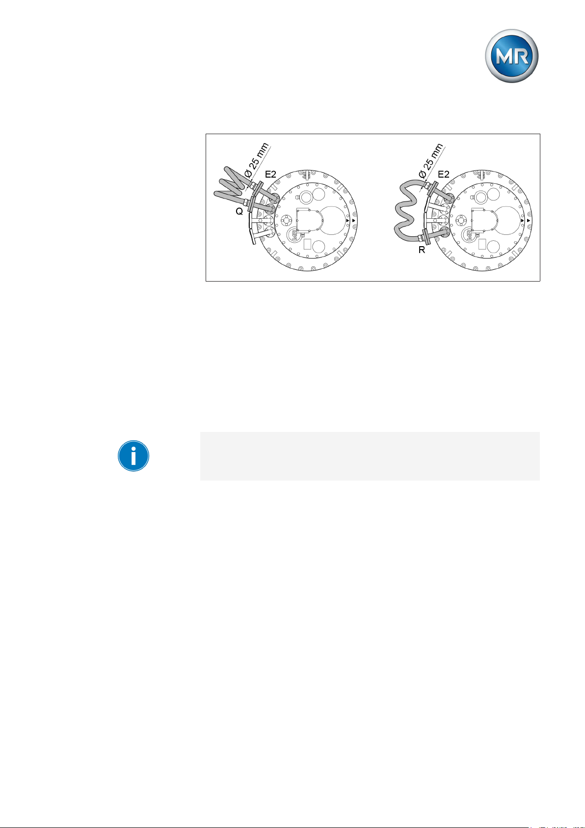
5 Mounting
2. Seal off unused pipe connections with a suitable blank cover.
Figure 51: Connecting lead
Vacuum-drying in the transformer tank
1. Heat up the on-load tap-changer in air at atmospheric pressure with a
temperature increase of about 10 °C/h to a final temperature of maximum 110 °C.
2. Pre-dry the on-load tap-changer in circulating air at a max. temperature
of 110 °C for a period of 20 hours.
3. Vacuum dry on-load tap-changer at between 105 °C and maximum 125
°C for at least 50 hours.
4. Residual pressure of no more than 10-3 bar.
If you wish to perform another transformer ratio test after drying, proceed as
described in the section "Performing transformer ratio test following drying".
5.2.6.2
Vapor-phase drying in the transformer tank
If you have not opened the kerosene drain plug in advance (e.g. after the
transformer ratio test), you have to open the kerosene drain plug before drying the kerosene in the transformer tank so that the kerosene condensate
can drain from the oil compartment.
The kerosene drain plug is located in the oil compartment base and is not
generally accessible from the outside. For this reason, you first have to remove the diverter switch insert, open the kerosene drain plug, and then install the diverter switch insert again. After the drying process, you have to remove the diverter switch insert again to close the kerosene drain plug.
Maschinenfabrik Reinhausen GmbH 2017 695293014/00 EN VACUTAP® VR I HD-Ex
Page 70
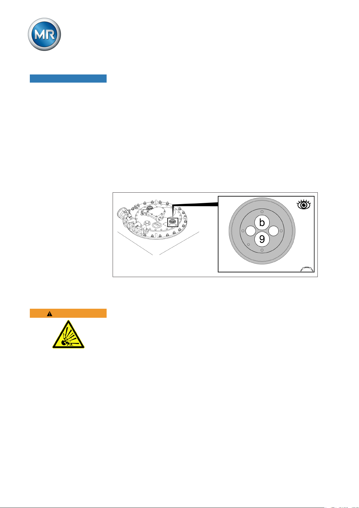
5 Mounting
NOTICE
5.2.6.2.1
5.2.6.2.1.1
Damage to the on-load tap-changer!
Damage to the on-load tap-changer and oil suction pipe due to incorrect order of installation.
► Strictly adhere to the order of installation. Make sure to always install
the diverter switch insert before inserting the oil suction pipe into the oil
compartment.
Removing diverter switch insert
Proceed as follows to remove the diverter switch insert.
Moving on-load tap-changer to adjustment position
► Switching the on-load tap-changer into the adjustment position (see
supplied connection diagram of the on-load tap-changer).
5.2.6.2.1.2
WARNING
Figure 52: Adjustment position
Removing on-load tap-changer head cover
Danger of explosion!
Danger of death from explosive gases under the on-load tap-changer head
cover!
► Ensure that there are no open flames, hot surfaces or sparks (for exam-
ple caused by static charging) in the immediate surroundings and that
none arise.
► De-energize all auxiliary circuits (for example tap-change supervisory
device) before removing the on-load tap-changer head cover.
► Do not operate any electrical devices during the work (for example risk
of sparks caused by impact wrench).
► Only use conductive and grounded hoses, pipes, and pump equipment
that are approved for flammable liquids.
Maschinenfabrik Reinhausen GmbH 201770 5293014/00 ENVACUTAP® VR I HD-Ex
Page 71

5 Mounting
NOTICE
Damage to the on-load tap-changer and transformer!
Small parts in the oil compartment may block the diverter switch insert,
thereby damaging the on-load tap-changer and transformer!
► Take care to avoid parts falling into the oil compartment.
► Check that you have the same number of small parts when disassem-
bling and reassembling.
1. Make sure that inspection window is sealed off with cover.
2. Loosen screws with locking elements on on-load tap-changer head cover.
Figure 53: On-load tap-changer head cover
3. NOTICE! Remove the on-load tap-changer head cover. Make sure that
sealing surfaces on the on-load tap-changer head cover and on-load
tap-changer head are in sound condition when removing and during all
other work and that the o-ring is also undamaged. Damaged sealing
surfaces lead to oil escaping and therefore to on-load tap-changer and
transformer damage.
Figure 54: On-load tap-changer head cover
Maschinenfabrik Reinhausen GmbH 2017 715293014/00 EN VACUTAP® VR I HD-Ex
Page 72

5 Mounting
5.2.6.2.1.3
5.2.6.2.1.4
Removing tap position indicator (version without multiple coarse change-over selector)
► Pull the spring clip off the shaft end and remove the tap position indica-
tor disc.
Figure 55: Tap position indicator disk
Removing tap position indicator from multiple coarse change-over selector with more than 35 operating positions
1. Ensure that the red marks on the panel, tap position indicator disk and
cover disk produce a continuous red line.
2. Remove countersunk head screw.
Figure 56: Countersunk head screw
Maschinenfabrik Reinhausen GmbH 201772 5293014/00 ENVACUTAP® VR I HD-Ex
Page 73

5 Mounting
3. Lever cover disk off underlying disk with flat screwdriver and pull out position-indication disk from between panel and bracket.
Figure 57: Cover disk and position-indication disk
4. Remove hexagon screws and associated lock tab.
Figure 58: Lock tab
5. Pull panel and bracket up and off indicator drive shaft.
Figure 59: Panel
Maschinenfabrik Reinhausen GmbH 2017 735293014/00 EN VACUTAP® VR I HD-Ex
Page 74
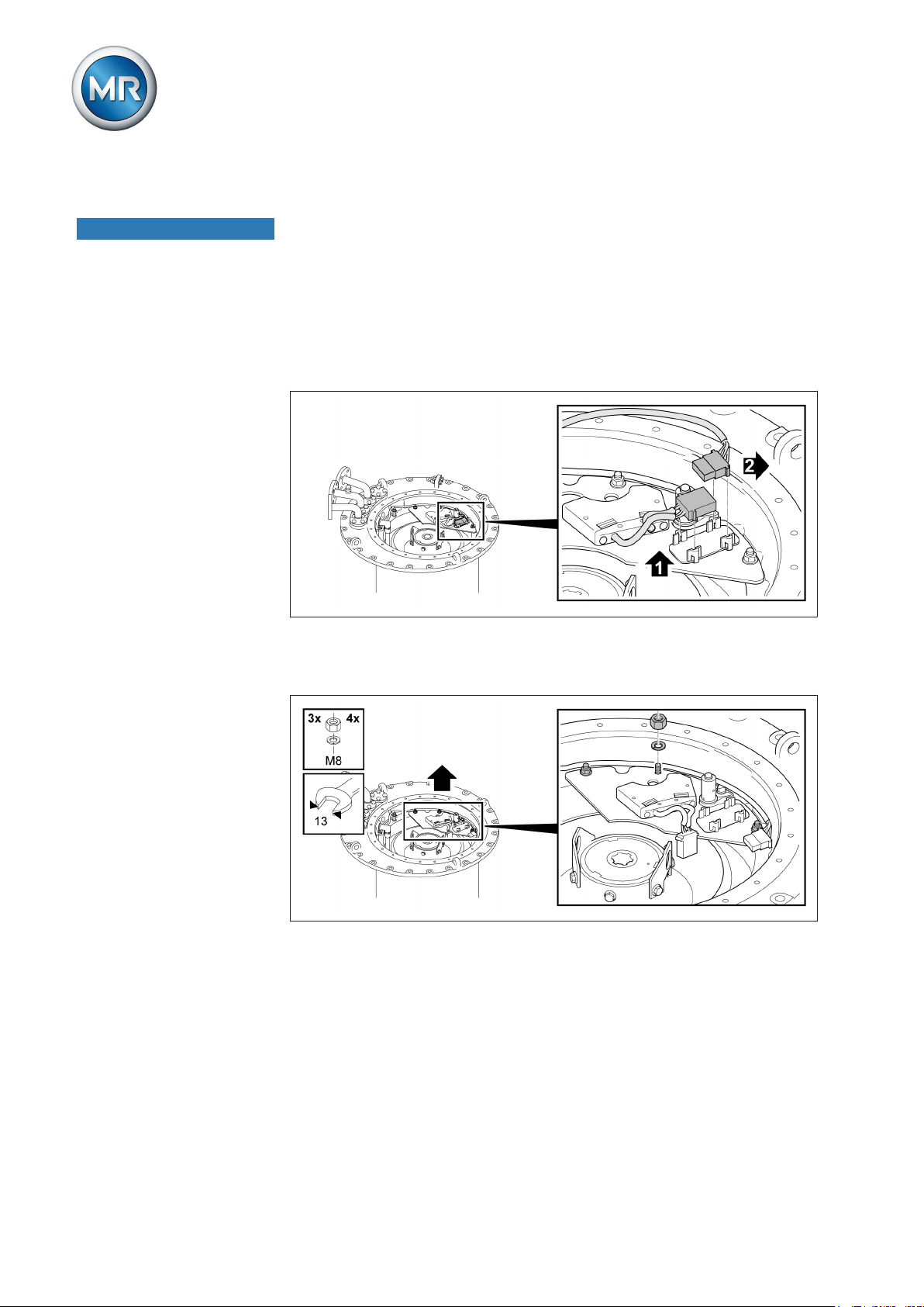
5 Mounting
5.2.6.2.1.5
NOTICE
Removing the tap-change supervisory device
Damage to the on-load tap-changer and transformer!
Removing the tap-change monitoring unit without due care may damage it,
thereby resulting in damage to the on-load tap-changer and transformer!
► Disconnect tap-change monitoring unit with care in order not to damage
or rip out the connecting leads.
1. Take the tap-change supervisory device plug connector out of the
mounting bracket and disconnect it.
Figure 60: Plug connector
2. Remove nuts and locking elements (3 or 4 depending on model) on the
mounting plate.
Figure 61: Mounting plate
Maschinenfabrik Reinhausen GmbH 201774 5293014/00 ENVACUTAP® VR I HD-Ex
Page 75

5 Mounting
3. Remove tap-change supervisory device with mounting plate and drive
shaft.
Figure 62: Tap-change supervisory device with mounting plate and drive shaft
4. Swivel the lead of the tap-change supervisory device out of the on-load
tap-changer head in direction indicated by the arrow until the cable will
not be damaged when the on-load tap-changer insert is pulled out.
Swiveling out the lead of the tap-change supervisory device
Maschinenfabrik Reinhausen GmbH 2017 755293014/00 EN VACUTAP® VR I HD-Ex
Page 76

5 Mounting
5.2.6.2.1.6
Removing the oil suction pipe
1. Remove cable ties from the oil suction pipe.
Figure 63: Cable tie
2. Pull oil suction pipe out of on-load tap-changer head.
5.2.6.2.1.7
Figure 64: Oil suction pipe
Lifting out diverter switch insert
1. By turning the coupling tube on the upper screening ring, align it in such
a manner that the triangular marks on the on-load tap-changer head and
those on the coupling tube match up.
Figure 65: Aligning the coupling tube
Maschinenfabrik Reinhausen GmbH 201776 5293014/00 ENVACUTAP® VR I HD-Ex
Page 77

5 Mounting
2. Insert the lifting gear in the eyebolts of the coupling tube and position
vertically above the diverter switch insert.
3. Lift the diverter switch insert slowly and vertically out of oil compartment.
5.2.6.2.2
Figure 66: Diverter switch insert
4. CAUTION! Place the diverter switch insert on a level surface and secure it against tipping. An unstably positioned diverter switch insert may
tip, resulting in injuries and damage.
5. NOTICE! Neither operate the diverter switch insert while removed nor
change the position of the tap selector coupling.Otherwise, the diverter
switch insert may be damaged when being reinstalled.
Opening kerosene drain plug
► NOTICE! Unscrew kerosene drain plug with extended socket wrench
counter-clockwise until it starts to get hard to turn.Never unscrew the
kerosene drain plug all the way.
Figure 67: Kerosene drain plug
Maschinenfabrik Reinhausen GmbH 2017 775293014/00 EN VACUTAP® VR I HD-Ex
Page 78

5 Mounting
5.2.6.2.3
5.2.6.2.3.1
Inserting diverter switch insert
Proceed as follows to insert the diverter switch insert.
Inserting diverter switch insert
1. Check that all six insulating shims are present in the energy accumulator carrier.
Figure 68: Insulating shim
Maschinenfabrik Reinhausen GmbH 201778 5293014/00 ENVACUTAP® VR I HD-Ex
Page 79

5 Mounting
2. To fit the diverter switch insert, ensure that the tap selector coupling is in
the adjustment position.
Figure 69: Adjustment markings in oil compartment base VACUTAP® VRC/VRE
Figure 70: Adjustment markings in oil compartment base VACUTAP® VRD/VRF
Maschinenfabrik Reinhausen GmbH 2017 795293014/00 EN VACUTAP® VR I HD-Ex
Page 80

5 Mounting
Figure 71: Adjustment markings in oil compartment base VACUTAP® VRG
3. Ensure that the diverter switch insert's energy accumulator is interlocked (the energy accumulator's eccentric disk is at its highest point).
4. Attach lifting gear to diverter switch insert and position diverter switch insert over oil compartment.
5. Align diverter switch insert such that the red markings at the top of the
energy accumulator and on the on-load tap-changer head are opposite
one another.
Maschinenfabrik Reinhausen GmbH 201780 5293014/00 ENVACUTAP® VR I HD-Ex
Page 81

5 Mounting
6. Slowly lower diverter switch insert until it meets the oil compartment
base.
Figure 72: Markings
7. Carefully press until energy accumulator carrier is in position. The shape
of the tap selector coupling ensures that coupling is only possible in the
correct position.
Maschinenfabrik Reinhausen GmbH 2017 815293014/00 EN VACUTAP® VR I HD-Ex
Page 82
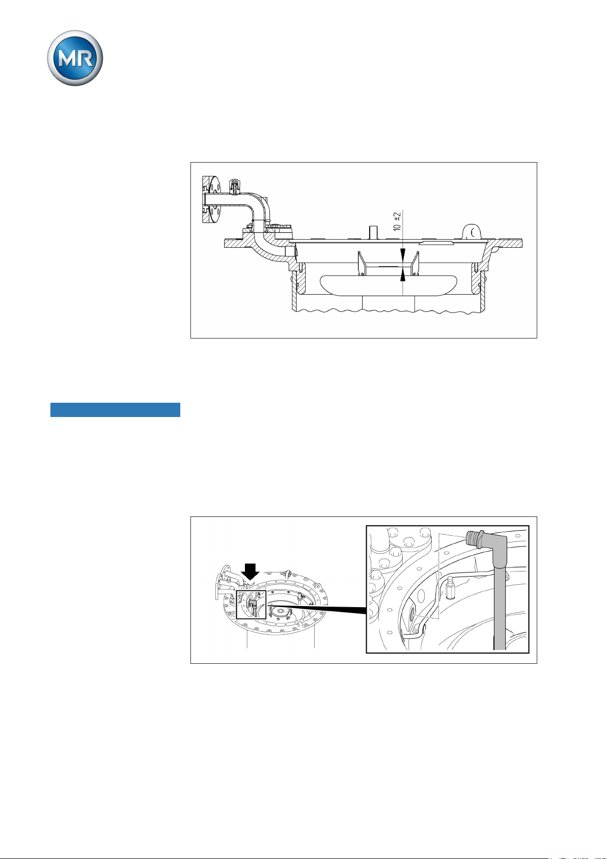
5 Mounting
8. Check the distance between the upper edge of the diverter switch insert
coupling tube and the on-load tap-changer head flange. The distance is
10 ± 2 mm (cover mounting and bell-type tank mounting).
Figure 73: Distance between the upper edge of the coupling tube and the on-load
tap-changer head flange
5.2.6.2.3.2
NOTICE
Inserting oil suction pipe
Damage to the on-load tap-changer!
Damage to the on-load tap-changer and oil suction pipe due to incorrect order of installation.
► Strictly adhere to the order of installation. Make sure to always install
the diverter switch insert before inserting the oil suction pipe into the oil
compartment.
1. Insert oil suction pipe into on-load tap-changer head.
Figure 74: Inserting oil suction pipe
Maschinenfabrik Reinhausen GmbH 201782 5293014/00 ENVACUTAP® VR I HD-Ex
Page 83

5 Mounting
2. Fasten oil suction pipe on retaining bracket with cable tie.
Figure 75: Fastening the oil suction pipe
5.2.6.2.3.3
Inserting the tap-change supervisory device
1. Insert tap-change supervisory device with mounting plate and drive
shaft.
Figure 76: Mounting plate with drive shaft
Maschinenfabrik Reinhausen GmbH 2017 835293014/00 EN VACUTAP® VR I HD-Ex
Page 84
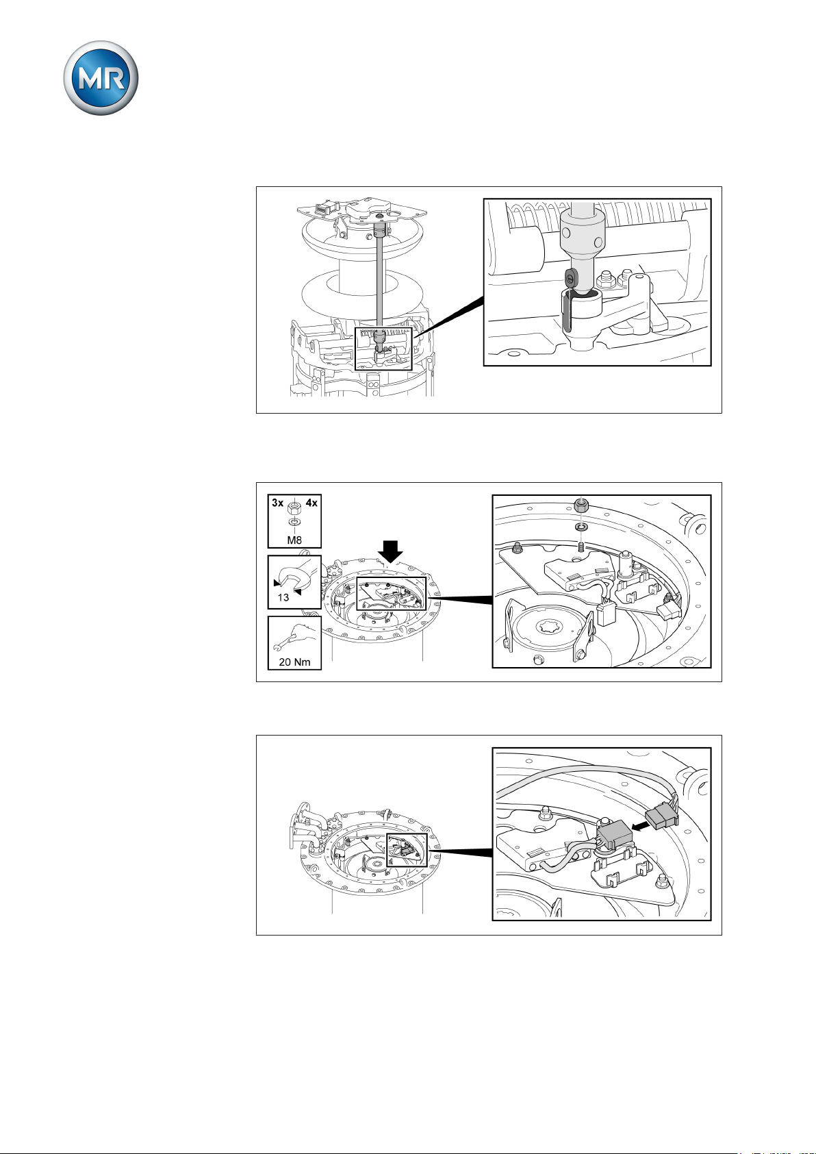
5 Mounting
2. Check that drive shaft feather key is seated correctly in the groove.
Figure 77: Feather key and groove
3. Secure mounting plate (3 or 4 nuts and locking elements depending on
model).
Figure 78: Mounting plate
4. Connect plug connector outside its bracket.
Figure 79: Plug connector
Maschinenfabrik Reinhausen GmbH 201784 5293014/00 ENVACUTAP® VR I HD-Ex
Page 85
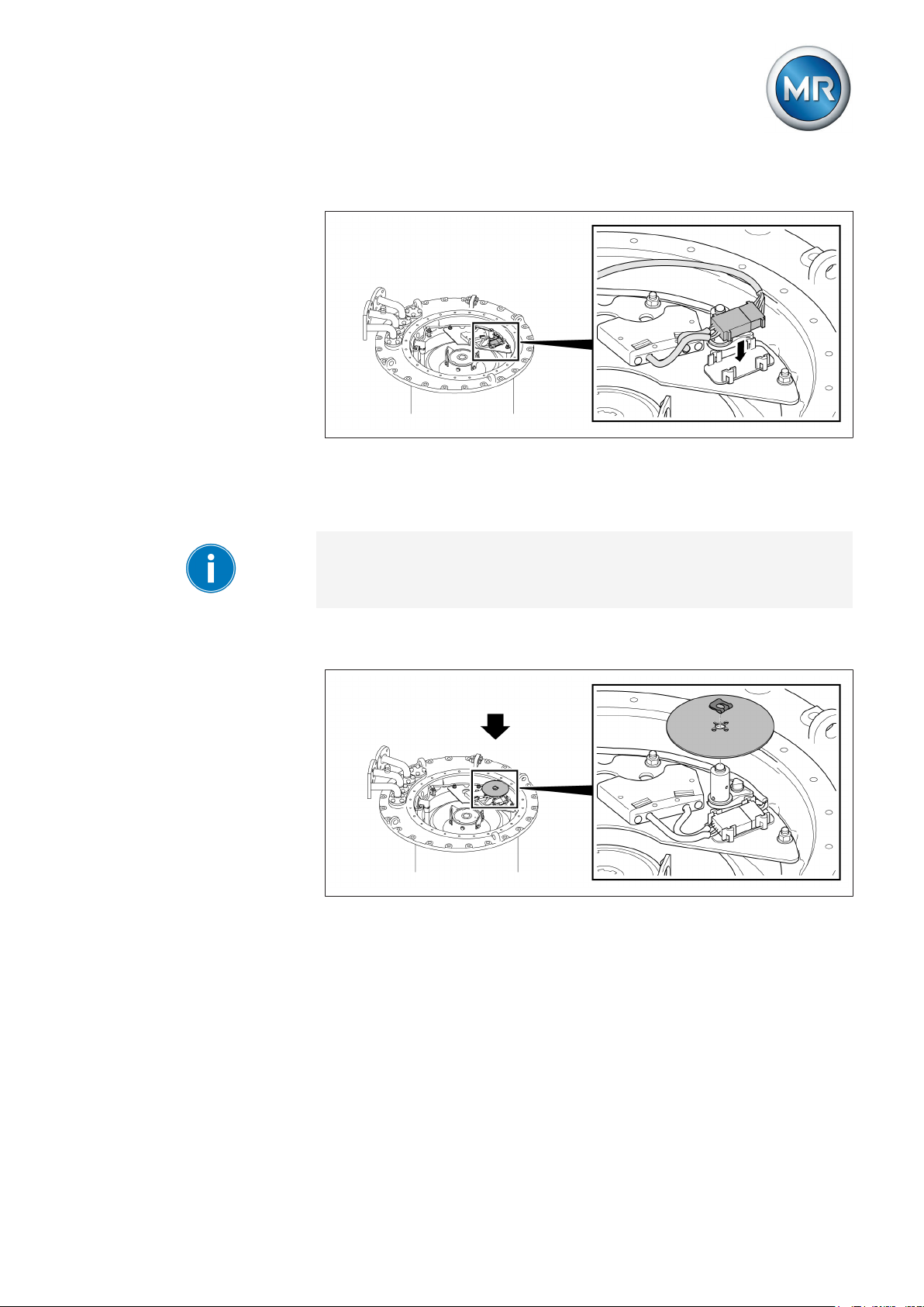
5 Mounting
5. Insert plug connector into the bracket.
Figure 80: Plug connector in bracket
5.2.6.2.3.4
Inserting the tap position indicator without multiple coarse changeover selector
Due to the coupling pin, the tap position indicator disc can only be installed
when in the correct position.
► Place tap position indicator disk on indicator drive shaft, slide spring clip
on to shaft end.
Figure 81: Tap position indicator disk
Maschinenfabrik Reinhausen GmbH 2017 855293014/00 EN VACUTAP® VR I HD-Ex
Page 86

5 Mounting
5.2.6.2.3.5
Inserting tap position indicator with multiple coarse change-over selector with more than 35 operating positions
1. Place panel with bracket on indicator drive shaft and fasten with hexagon screws and associated lock tab.
Figure 82: Fitting panel
2. Insert position-indication disk horizontally between panel and bracket
and fit cover disk. Align tap position indicator disc and cover disk to produce a continuous red line.
Figure 83: Inserting position-indication disk
Maschinenfabrik Reinhausen GmbH 201786 5293014/00 ENVACUTAP® VR I HD-Ex
Page 87

5 Mounting
3. Secure cover disk with countersunk head screw. The countersunk head
screw must be suitable for center-punching.
Figure 84: Fastening cover disk
4. Secure countersunk head screw by center-punching.
5.2.6.2.3.6
Securing on-load tap-changer head cover
1. NOTICE! Place on-load tap-changer head cover on on-load tap-changer head and take care not to damage the o-ring inserted in the on-load
tap-changer head cover. A damaged o-ring leads to oil escaping and
therefore to damage of the on-load tap-changer. Also ensure that the
red triangular marks on the on-load tap-changer head and the on-load
tap-changer head cover match up.
Figure 85: On-load tap-changer head cover with o-ring
Maschinenfabrik Reinhausen GmbH 2017 875293014/00 EN VACUTAP® VR I HD-Ex
Page 88
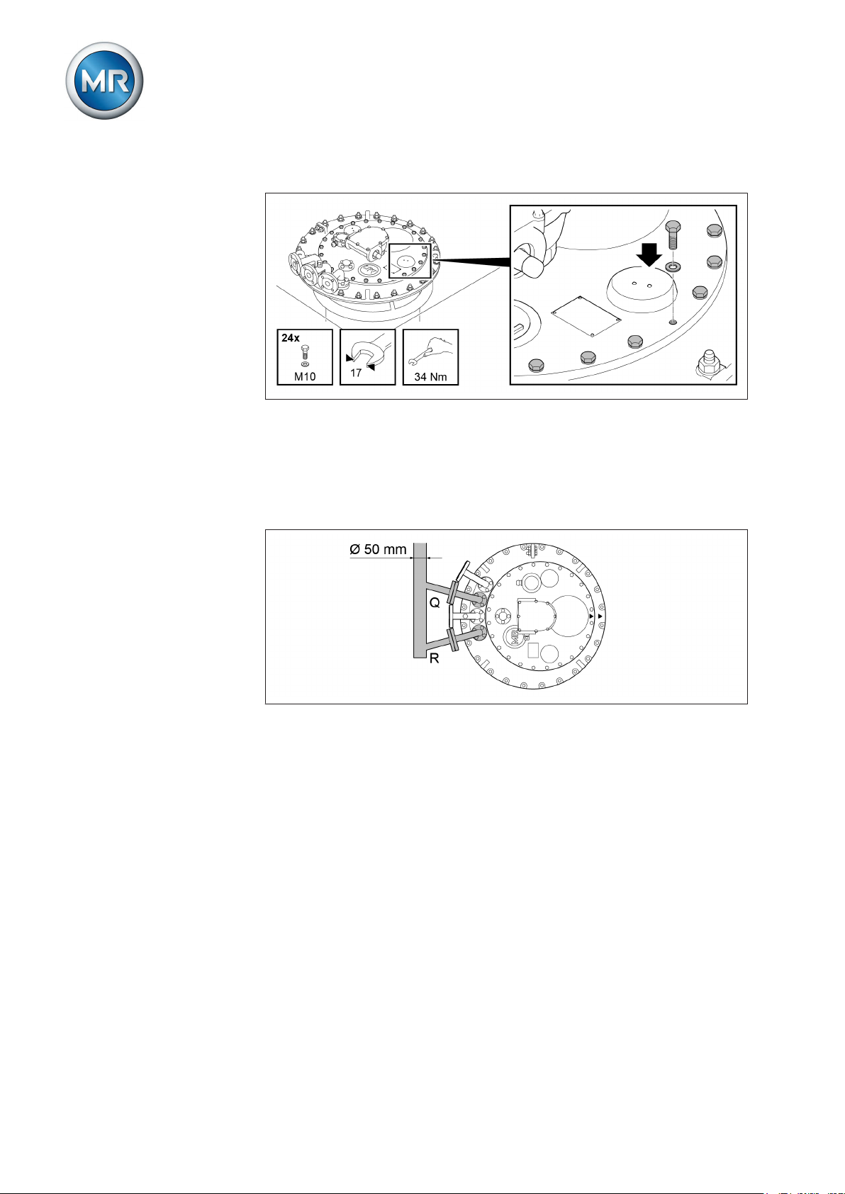
5 Mounting
2. Screw on-load tap-changer head cover using screws and washers.
Figure 86: On-load tap-changer head cover
5.2.6.2.4
Drying the on-load tap-changer
1. Connect pipe connections R and Q of on-load tap-changer head to the
kerosene vapor lead using one shared lead.
2. Seal off unused pipe connections with a suitable blank cover.
Figure 87: Shared lead
Vapor-phase drying in the transformer tank
1. Supply kerosene vapor at a temperature of around 90 °C. Keep this
temperature constant for 3 to 4 hours.
2. Increase the kerosene vapor temperature by approx. 10 °C/hour to the
desired final temperature of max. 125 °C at the on-load tap-changer.
3. Vacuum dry on-load tap-changer at between 105 °C and maximum 125
°C for at least 50 hours.
4. Residual pressure of no more than 10-3 bar.
5.2.6.2.5
Closing kerosene drain plug
1. Removing [► 70] the diverter switch insert.
2. Close kerosene drain plug with extended socket wrench by turning
clockwise (tightening torque 20 Nm).
3. Inserting [► 78] the diverter switch insert.
Maschinenfabrik Reinhausen GmbH 201788 5293014/00 ENVACUTAP® VR I HD-Ex
Page 89

5 Mounting
If you wish to perform another transformer ratio test after drying, proceed as
described in the section "Performing transformer ratio test following drying".
5.2.7
NOTICE
Carrying out transformer ratio test after drying
To perform the transformer ratio test, proceed as follows:
Damage to property!
Damage to on-load tap-changer due to transformer ratio test being incorrectly performed!
► Make sure that the selector/de-energized tap changer is fully immersed
in transformer oil and that the oil compartment of the on-load tapchanger is completely filled with oil.
► The on-load tap-changer/de-energized tap-changer can be operated in
the following temperature range:
- when surrounded by transformer oil: –25 °C…+105 °C and up to
+115 °C as per IEC 60214-1 during emergency transformer operation
in accordance with IEC 60076-7
- with synthetic esters in accordance with IEC 61099: –15 °C…+105 °C
and up to +115 °C as per IEC 60214-1 during emergency transformer
operation in accordance with IEC 60076-7
► Only switch the on-load tap-changer from one operating position to the
next via the upper gear unit. You can use a short tube (diameter
25 mm) with screwed-in coupling bolt (diameter 12 mm) with a hand
wheel or crank for this. When using a drill, do not exceed a maximum
speed of 250 rpm.
► Always check the operating position reached through the inspection
window in the on-load tap-changer head cover. Never overshoot the
end positions, which are indicated in the connection diagram supplied
with the delivery.
► For multiple-column applications with a shared drive, link all on-load
tap-changer heads to one another using the horizontal drive shaft part.
Maschinenfabrik Reinhausen GmbH 2017 895293014/00 EN VACUTAP® VR I HD-Ex
1. Switch on-load tap-changer into the desired operating position. The
diverter switch operation can be heard distinctly.
When actuating the change-over selector, a higher torque is required.
Page 90
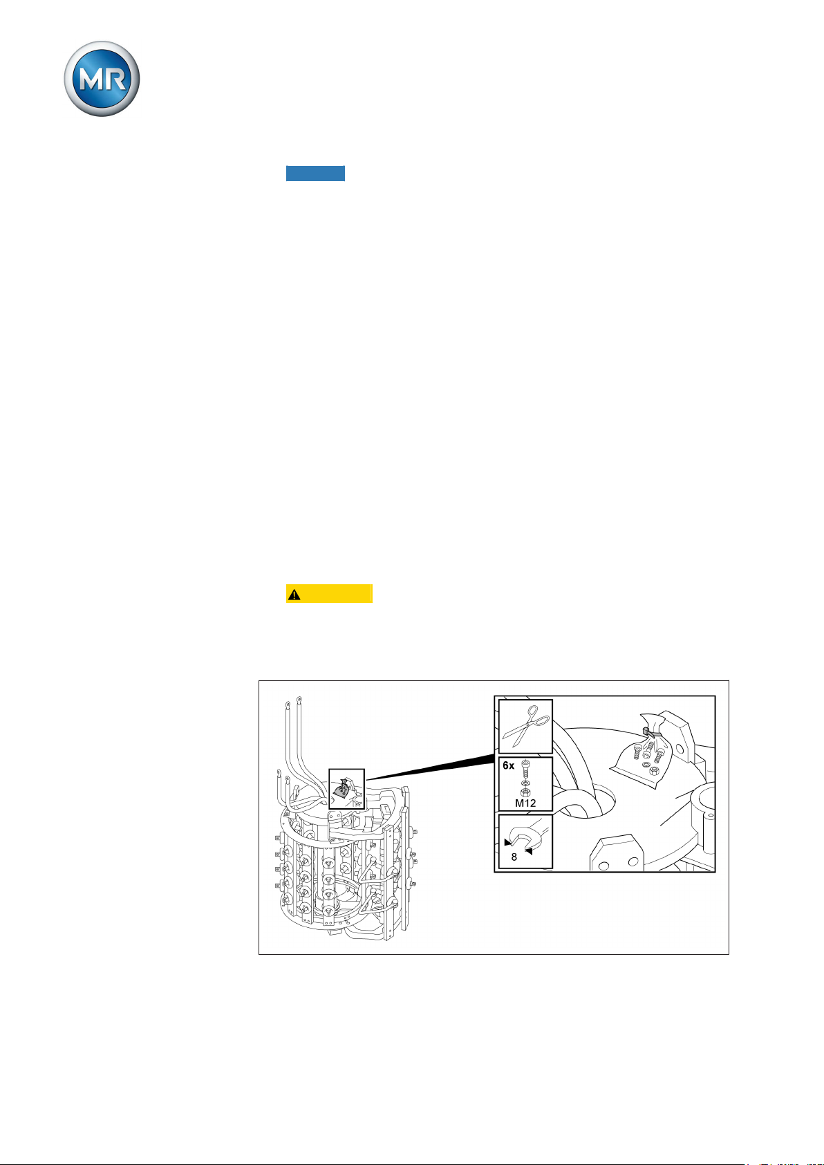
5 Mounting
2. NOTICE! After operating the diverter switch, continue to crank 2.5 revolutions in the same direction on the drive shaft of the upper gear unit in
order to correctly end the tap-change operation. An incomplete tapchange operation may damage the on-load tap-changer!
3. Carry out the transformer ratio test.
4. Repeat the transformer ratio test in all operating positions.
5. Once the transformer ratio test is complete, return on-load tap-changer
to its adjustment position (see supplied connection diagram of the onload tap-changer).
Installing on-load tap-changer in transformer (bell-type
5.3
tank version)
The following chapters explain how to install the on-load tap-changer in the
transformer.
5.3.1
5.3.1.1
Inserting on-load tap-changer into supporting structure
Proceed as follows to insert the on-load tap-changer in the supporting structure:
Securing tap selector on oil compartment of the on-load tap-changer VRC/VRE
1. CAUTION! Place the tap selector on a level surface and secure it
against tipping. An unstably positioned tap selector may tip, resulting in
serious injuries and damage.
2. Remove plastic bag with fastening materials from the tap selector and
lay out.
Figure 88: Plastic bag with fastening materials
Maschinenfabrik Reinhausen GmbH 201790 5293014/00 ENVACUTAP® VR I HD-Ex
Page 91
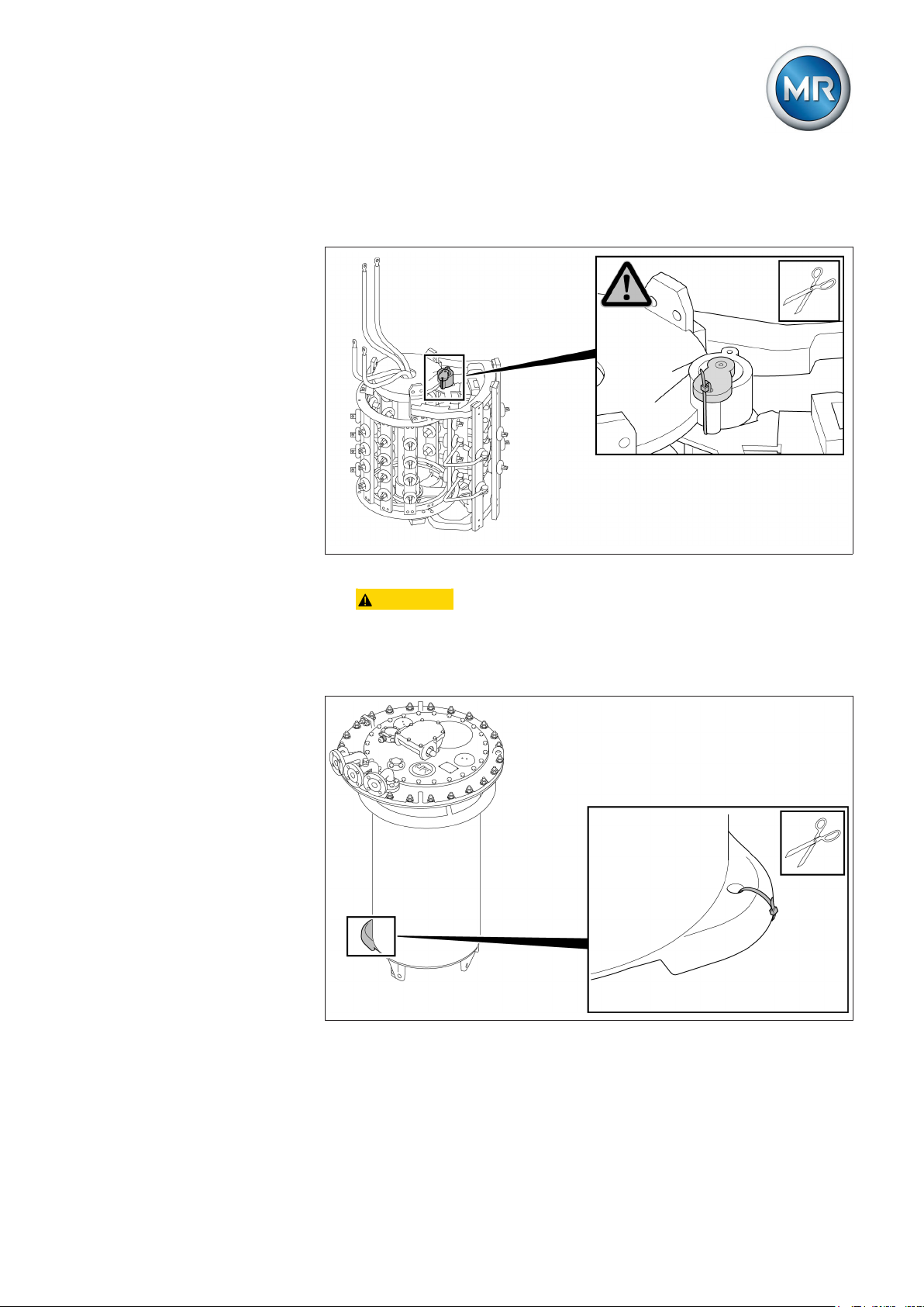
5 Mounting
3. Remove the blocking strip from the tap selector coupling. Once the
blocking strip is removed, the tap selector coupling must no longer be
turned.
Figure 89: Blocking strip
4. CAUTION! Place the oil compartment on a level surface and secure
it against tipping. An unstably positioned oil compartment may tip over,
resulting in serious injuries and damage.
5. Remove the blocking device from the coupling of the oil compartment
base.
Figure 90: Blocking strip
6. Lift the oil compartment by hooking up the on-load tap-changer head
and carefully raise above tap selector.
Maschinenfabrik Reinhausen GmbH 2017 915293014/00 EN VACUTAP® VR I HD-Ex
Page 92
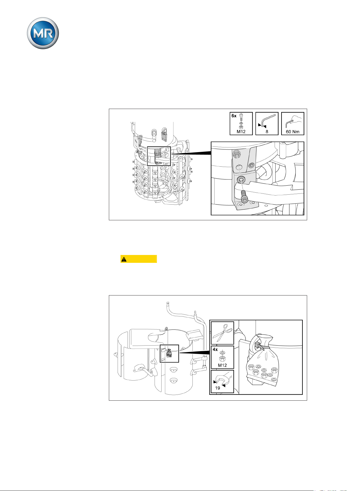
5 Mounting
7. Align the position of both coupling parts and attachment points on the oil
compartment and the tap selector with one another. The correct position
of the two coupling parts is shown in the adjustment plans in the appendix.
8. Screw tap selector onto oil compartment.
5.3.1.2
Figure 91: Tap selector with oil compartment
Securing tap selector on oil compartment of the on-load tap-changer VRC/VRE
1. CAUTION! Place the tap selector on a level surface and secure it
against tipping. An unstably positioned tap selector may tip, resulting in
serious injuries and damage.
2. Remove plastic bag with fastening materials from the tap selector and
lay out.
Figure 92: Plastic bag with fastening materials
Maschinenfabrik Reinhausen GmbH 201792 5293014/00 ENVACUTAP® VR I HD-Ex
Page 93
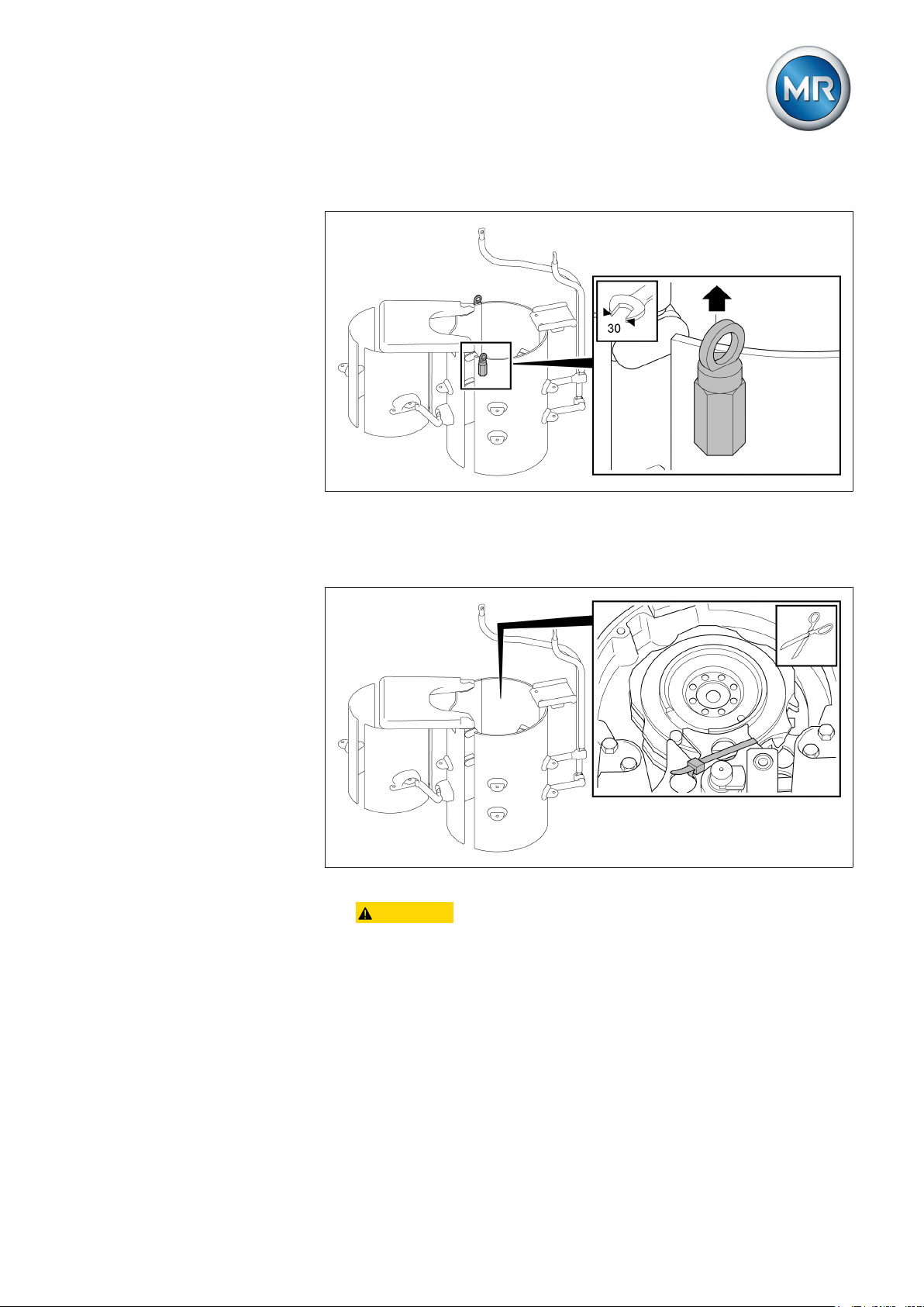
5 Mounting
3. Remove the ring nuts from the tap selector.
Figure 93: Ring nut
4. Remove the blocking strip from the tap selector coupling. Once the
blocking strip is removed, the tap selector coupling must no longer be
turned.
Figure 94: Blocking strip
5. CAUTION! Place the oil compartment on a level surface and secure
it against tipping. An unstably positioned oil compartment may tip over,
resulting in serious injuries and damage.
Maschinenfabrik Reinhausen GmbH 2017 935293014/00 EN VACUTAP® VR I HD-Ex
Page 94

5 Mounting
6. Lift the oil compartment by hooking up the on-load tap-changer head
and remove the blocking device on the coupling of the oil compartment
base.
Figure 95: Blocking plate and shackle
7. Carefully raise oil compartment above tap selector.
8. Align the position of both coupling parts and attachment points on the oil
compartment and the tap selector with one another. The correct position
of the two coupling parts is shown in the adjustment plans in the appendix.
Maschinenfabrik Reinhausen GmbH 201794 5293014/00 ENVACUTAP® VR I HD-Ex
Page 95
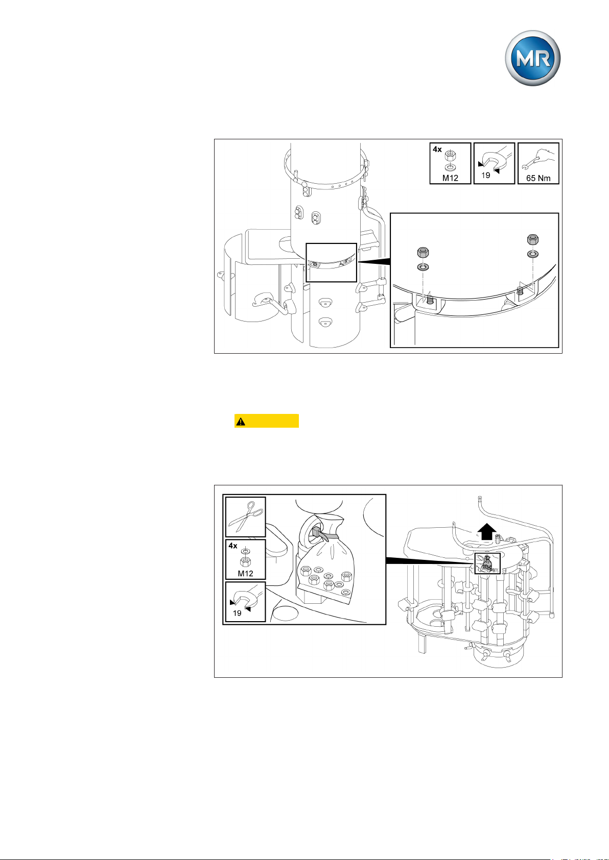
5 Mounting
9. Screw tap selector onto oil compartment.
5.3.1.3
Figure 96: Tap selector with oil compartment
Securing tap selector on oil compartment of the on-load tap-changer VRG
1. CAUTION! Place the tap selector on a level surface and secure it
against tipping. An unstably positioned tap selector may tip, resulting in
serious injuries and damage.
2. Remove plastic bag with fastening materials from the tap selector and
lay out.
Figure 97: Plastic bag with fastening materials
Maschinenfabrik Reinhausen GmbH 2017 955293014/00 EN VACUTAP® VR I HD-Ex
Page 96

3. Remove the ring nuts from the tap selector.
Figure 98: Ring nut
5 Mounting
4. Remove the blocking strip from the tap selector coupling. Once the
blocking strip is removed, the tap selector coupling must no longer be
turned.
Figure 99: Blocking strip
5. CAUTION! Place the oil compartment on a level surface and secure
it against tipping. An unstably positioned oil compartment may tip over,
resulting in serious injuries and damage.
Maschinenfabrik Reinhausen GmbH 201796 5293014/00 ENVACUTAP® VR I HD-Ex
Page 97
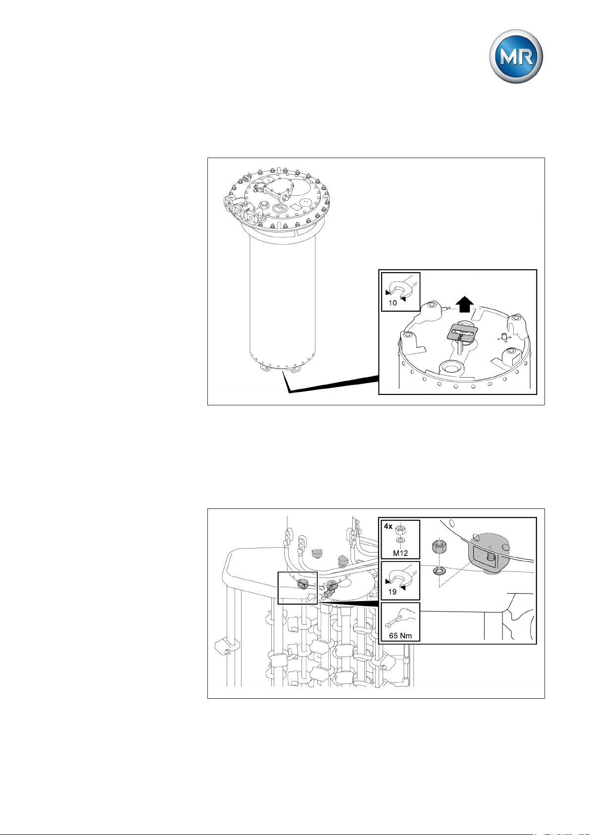
5 Mounting
6. Lift the oil compartment by hooking up the on-load tap-changer head
and remove the blocking device on the coupling of the oil compartment
base.
Figure 100: Blocking plate and shackle
7. Carefully raise oil compartment above tap selector.
8. Align the position of both coupling parts and attachment points on the oil
compartment and the tap selector with one another. The correct position
of the two coupling parts is shown in the adjustment plans in the appendix.
9. Screw tap selector onto oil compartment.
Figure 101: Tap selector with oil compartment
Maschinenfabrik Reinhausen GmbH 2017 975293014/00 EN VACUTAP® VR I HD-Ex
Page 98

5 Mounting
5.3.1.4
Connecting tap-selector connecting leads
Proceed as follows to connect the tap-selector connecting leads:
1. NOTICE! Carefully screw tap-selector connecting leads to connecting
piece or ring segment. Comply with specified tightening torque and secure screw connection. Failure to do so may result in damage to the onload tap-changer and transformer.
2. Attach screening caps to screw connection.
Figure 102: Connecting piece
5.3.1.5
Figure 103: Ring segment
Inserting on-load tap-changer into supporting structure
1. NOTICE! Using spacers, insert on-load tap-changer vertically into supporting structure (maximum 1° deviation from the vertical) so that the
on-load tap-changer reaches its final installation height and only has to
be raised a maximum of 5 to 20 mm after fitting the bell-type tank. If this
is not done, once the tap winding and on-load tap-changer take-off lead
Maschinenfabrik Reinhausen GmbH 201798 5293014/00 ENVACUTAP® VR I HD-Ex
Page 99

5 Mounting
are connected, tension may occur which will damage the on-load tapchanger and transformer. There is also a risk of malfunctions from selector contacts moving to the closing position incorrectly.
Figure 104: On-load tap-changer with spacers on supporting structure
2. Remove red supports on selector base (if present).
Maschinenfabrik Reinhausen GmbH 2017 995293014/00 EN VACUTAP® VR I HD-Ex
Page 100

5 Mounting
3. Temporarily fasten on-load tap-changer to supporting structure. The
supporting flange has through holes for this purpose.
Figure 105: Fastening the on-load tap-changer
5.3.2
Connecting the tap winding and on-load tap-changer take-off lead
NOTICE
5.3.2.1
Damage to the on-load tap-changer!
Connecting leads which place mechanical strain on the on-load tap-changer
will damage the on-load tap-changer!
► Establish connections carefully.
► Do not twist connection contacts.
► Connect connecting leads without warping or deforming.
► If necessary, use an expansion loop for connecting leads.
► Fit screening caps provided to screw connections.
The tap winding and on-load tap-changer take-off lead must be connected in
accordance with the connection diagram included with the delivery.
Tap selector connection contacts VRC/VRE
The selector connection contacts are indicated on the selector bars, have
crimped ends and a through-hole for M10 screws to allow the tap-selector
connecting leads to be connected with cable shoes.
The screening caps are supplied separately.
In this case a locking washer must be placed below each screening cap. The
M10 connection screws, the nuts, and locking washers are not included in
the scope of delivery.
Maschinenfabrik Reinhausen GmbH 2017100 5293014/00 ENVACUTAP® VR I HD-Ex
 Loading...