

Page 1
Monitoring System
TAPGUARD® 260
Quick Reference Guide
2349487/01 EN
Page 2

1 Introduction
Maschinenfabrik Reinhausen 20132 2349487/01 ENTAPGUARD® 260
Introduction
This quick reference guide contains information for quick start-up of the device. It does not provide comprehensive operating instructions.
Manufacturer
The product is manufactured by:
Maschinenfabrik Reinhausen GmbH
Falkensteinstraße 8
93059 Regensburg, Germany
Tel.: (+49) 9 41/40 90-0
Fax: (+49) 9 41/40 90-7001
E-mail: sales@reinhausen.com
Further information on the product and copies of this technical file are available from this address if required.
Completeness
This technical file is incomplete without the supporting documentation.
Supporting documents
The following documents apply to this product:
▪ Operating instructions
▪ Quick reference guide
▪ Connection diagrams
Also observe generally valid legislation, standards, guidelines and specifications on accident prevention and environmental protection in the respective
country of use.
1
1.1
1.2
1.3
Page 3
2 Product description
Maschinenfabrik Reinhausen 2013 32349487/01 EN TAPGUARD® 260
Product description
This chapter contains an overview of the design and function of the product.
Operating concept
The monitoring system is operated by keys for parameterization and configuration on the front panel of the device. Alternatively, configuration is also
possible via the TAPCON®-trol visualization software.
The monitoring system is equipped with a key lock to prevent unintentional
operation. To activate or deactivate, press the and keys
simultaneously.
Manual mode
Manual mode is an additional safety feature of the monitoring system and
protects the parameters from being unintentionally changed.
The following activities cannot be performed until you have activated manual
mode:
▪ Acknowledging events
▪ Acknowledging maintenance
▪ Changing parameters
You can change the parameters regardless of manual mode via the visualization software TAPCON®-trol.
To activate manual mode, proceed as follows:
► Press .
ð The relevant LED lights up.
Manual mode is activated. If no key on the monitoring system has been
pressed after more than 5 minutes, manual mode is automatically deactivated.
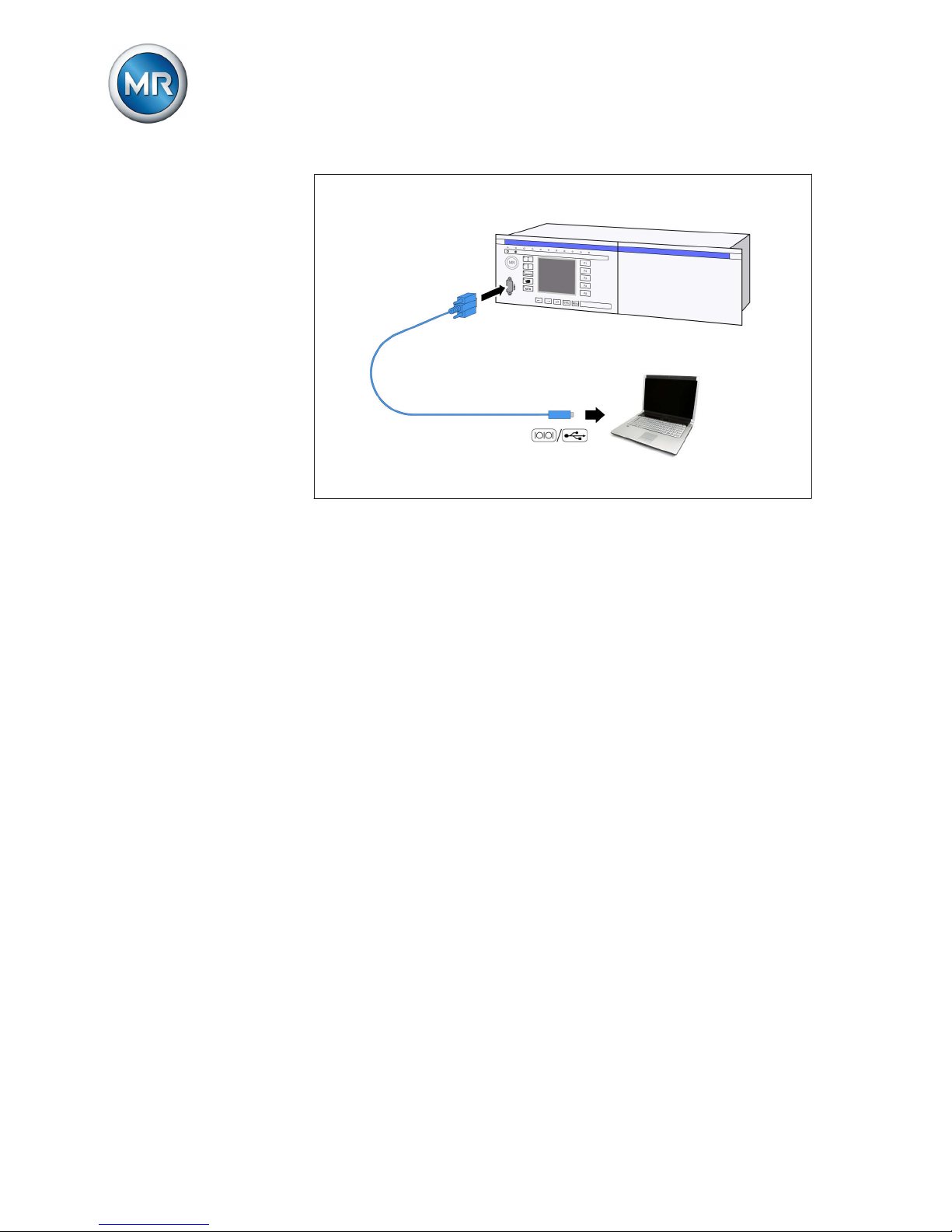
Serial interface
The parameters for the device can be set using a PC. The COM 1 (RS232)
serial interface on the front panel is provided for this purpose. You can use
the connection cable supplied to establish a connection to your PC via the
RS232 or USB port (using the optional USB adapter).
TAPCON®-trol software is needed for parameterization via the serial interface. The software and the related operating instructions are contained on
the CD provided.
2
2.1
2.2
Page 4
2 Product description
Maschinenfabrik Reinhausen 20134 2349487/01 ENTAPGUARD® 260
Figure 1: Device connection to a PC
Page 5
3 Mounting
Maschinenfabrik Reinhausen 2013 52349487/01 EN TAPGUARD® 260
Mounting
This chapter describes how to correctly mount and connect the device. Note
the connection diagrams provided.
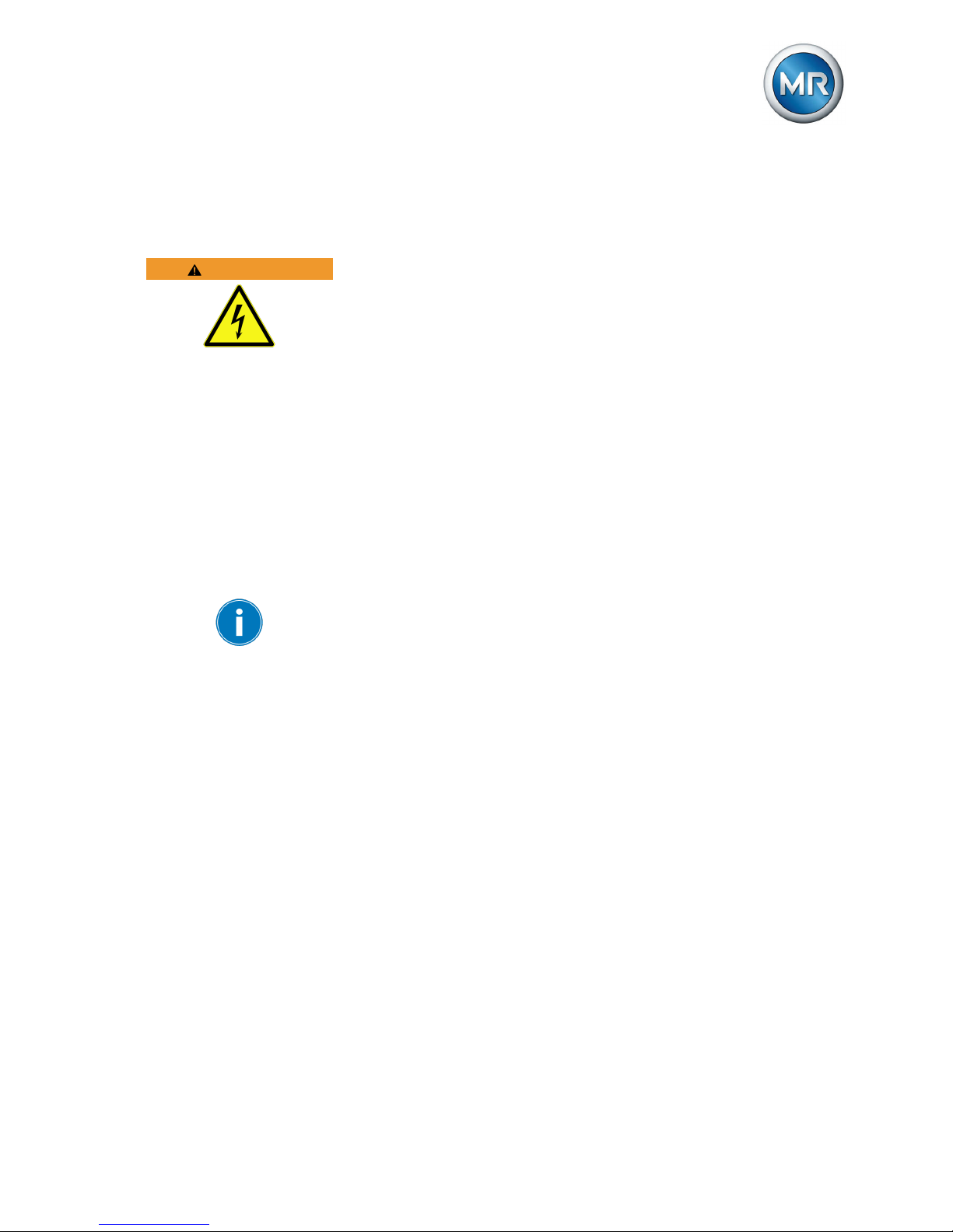
WARNING
Electric shock
Danger of death due to electrical voltage.
► De-energize device and system periphery and lock to prevent switching
back on again.
Installing and wiring temperature sensors
The following sections describe how to install and wire the temperature sensors for the diverter switch oil and the transformer oil.
Connecting temperature sensor for on-load tap-changer oil
A temperature sensor is mounted in the on-load tap-changer head cover in
each on-load tap-changer. You have to perform the wiring in accordance
with the connection diagram that came with the motor-drive unit. Please observe the following:
Do not loop the temperature sensor connecting leads when laying because
this may cause voltage coupling and result in measurement errors.
To connect the temperature sensor for the on-load tap-changer oil, proceed
as follows:
1. Place the shielding of the sensor connecting lead on the grounding rails
in the motor-drive unit.
2. Connect the sensor connecting lead to the terminals in the motor-drive
unit as shown in the connection diagram.
3
3.1
3.1.1
Page 6

3 Mounting
Maschinenfabrik Reinhausen 20136 2349487/01 ENTAPGUARD® 260
3. Remove the temperature sensor cover on the on-load tap-changer head
cover.
Figure 2: Removing temperature sensor cover
4. Remove the shielding of the sensor connecting lead on the temperature
sensor.
5.
NOTICE! Do not place shielding in temperature sensor. Insulate tem-
perature sensor connecting leads using shrink tubing such that the
shielding is no longer exposed. If this is not done, current may flow via
the shielding and the device may be damaged.
Figure 3: Correct insulation of connecting lead shielding
1 Exposed shielding 2 Correctly insulated connecting
lead
6. NOTICE! Guide connecting leads into temperature sensor. Ensure that
the cable entry point is watertight. If not, the temperature sensor may be
damaged.
Page 7
3 Mounting
Maschinenfabrik Reinhausen 2013 72349487/01 EN TAPGUARD® 260
7. Wire sensor connecting lead in the temperature sensor as shown in the
connection diagram.
8. Close temperature sensor cover.
When you close the temperature sensor cover, make sure that the seal is
correctly positioned and that no connecting leads are wedged in.
9. Ground the temperature sensor housing on the on-load tap-changer using the grounding cable.
The temperature sensor is connected. Please continue with the next section
to connect the transformer oil sensor.
Connecting temperature sensor for transformer oil
You have to perform the wiring in accordance with the connection diagram
that came with the motor-drive unit.
Do not loop the temperature sensor connecting leads when laying because
this may cause voltage coupling and result in measurement errors.
1. Open the transformer thermometer case.
2. Fill the thermometer case with oil until the heat conduction sensor is
completely immersed in oil.
3. Place the shielding of the sensor connecting lead on the grounding rails
in the motor-drive unit.
4. Connect the sensor connecting lead to the terminals in the motor-drive
unit as shown in the connection diagram.
5. Remove the temperature sensor cover.
6. Remove the shielding for the sensor connecting lead on the transformer
oil sensor.
7.
NOTICE! Do not place shielding in temperature sensor. Insulate tem-
perature sensor connecting leads using shrink tubing such that the
shielding is no longer exposed. If this is not done, current may flow via
the shielding and the device may be damaged.
8.
NOTICE! Guide connecting leads into temperature sensor. Ensure that
the cable entry point is watertight. If not, the temperature sensor may be
damaged.
9. Wire sensor connecting lead in the temperature sensor as shown in the
connection diagram.
10. Mount the temperature sensor cover.
3.1.2
Page 8

3 Mounting
Maschinenfabrik Reinhausen 20138 2349487/01 ENTAPGUARD® 260
When you close the temperature sensor cover, make sure that the seal is
correctly positioned and that no connecting leads are wedged in.
Checking temperature sensors
After connecting the temperature sensors, check the values measured. To
do so, proceed as follows:
1. Switch on device and wait until the operating screen appears.
2. > Info > Meas. values.
ð Measured values.
► Compare the "Transf. oil temp." and "OLTC oil temp." measured values
shown with the real values.
Connecting tap-change supervisory control
The tap-change supervisory control is integrated in the tap changer. The
connecting leads are led out through a terminal box on the tap changer
head's pipe connection.
Do not loop the tap-change supervisory control connecting leads when laying because this can cause voltage coupling and result in measurement errors.
To connect the tap-change supervisory control to the device, proceed as follows:
1. Remove terminal box cover.
2. Remove connecting lead shielding.
3.
NOTICE! Do not place shielding in terminal box. Insulate tap-change
supervisory control's connecting leads with a shrink-fit hose such that
the shielding is not exposed. If this is not done, current may flow via the
shielding and the device may be damaged.
3.1.3
3.2
Page 9

3 Mounting
Maschinenfabrik Reinhausen 2013 92349487/01 EN TAPGUARD® 260
4. Insert connecting lead through terminal area into terminal box.
Figure 5: Connection of the tap-change supervisory control
5. Wire connecting lead in accordance with motor-drive unit's connection
diagram.
6. Fit terminal box cover.
When you close the temperature sensor cover, make sure that the seal is
correctly positioned and that no connecting leads are wedged in.
Connecting load current measurement
You have to perform the wiring for the load current measurement in accordance with the connection diagram that came with the motor-drive unit. The
following signals can be wired:
▪ 4...20 mA (AD8 card)
▪ 0.2 A, 1 A or 5 A (MI card)
To connect the load current measurement, proceed as follows:
1. Wire load current measurement in accordance with motor-drive unit's
connection diagram.
2. Only with load current measurement via MI card: Remove short-circuiting jumper (see connection diagram, terminals X1:255 and X1:256 in
standard version).
3. Check load current shown on device display by pressing the
key in
the main screen.
3.3
Page 10

3 Mounting
Maschinenfabrik Reinhausen 201310 2349487/01 ENTAPGUARD® 260
ð If, after a minute, a value for the load current is displayed that does
not equal the on-load tap-changer's maximum current, the connections are correctly wired.
A load current is only displayed when there is a valid signal at the input
used for the load current measurement (> 0 A when measuring via MI card
or > 4 mA when measuring via AD8 card). If there is no valid signal, the
maximum on-load tap-changer current is displayed.
Wiring status relay
The status relay reports the current status of the device. Maschinenfabrik
Reinhausen recommends transferring the signal to your control room. To do
so, proceed as follows:
► Wire status relay IO-X1:01/02/03 to your control room in accordance
with the connection diagram.
3.4
Page 11

4 Commissioning
Maschinenfabrik Reinhausen 2013 112349487/01 EN TAPGUARD® 260
Commissioning
You need to set several parameters and perform function tests before commissioning the device. These are described in the following sections.
NOTICE
Damage to device and system periphery
An incorrectly connected device can lead to damages in the device and system periphery.
► Check the entire configuration before commissioning.
► Prior to commissioning, be sure to check the actual voltage and operat-
ing voltage.
Setting COM1 baud rate
You can use the baud rate parameter Baud rate to set the COM1 interface's
baud rate. You can select various baud rates.
To set the baud rate, proceed as follows:
1. Press .
ð The manual mode is active and the associated LED lights up.
2. > General > Press until the desired display appears.
ð COM1 setting.
3. Press or to set the option you want.
4. Press .
ð The baud rate is set.
Setting date and time
You must set the system date and system time on the device. You must set
the date and time in the following formats:
Date Time
DD.MM.YY HH:MM:SS
Table 1: Formats
The time does not switch from daylight saving time to standard time and
back automatically. You have to change the time manually.
To set the time, proceed as follows:
4
4.1
4.2
Page 12

4 Commissioning
Maschinenfabrik Reinhausen 201312 2349487/01 ENTAPGUARD® 260
1. Press .
ð The manual mode is active and the associated LED lights up.
2. > > General > Press until the desired display appears.
ð Date and time
3. Press to highlight a digit.
ð The desired position is highlighted and the value can be changed.
4. Press to increase the value or to reduce it.
5. Press .
ð The date and time are set.
Setting the language
You can use this parameter to set the display language for the device. To
set the language, proceed as follows:
1. Press .
ð The manual mode is active and the associated LED lights up.
2. > General.
ð Language
3. Press or to select the required language.
4. Press .
ð The language is set.
Activating commissioning mode
When commissioning the transformer at the installation site, you must use
the parameter to activate commissioning mode. This resets the maintenance
intervals.
To activate commissioning mode, proceed as follows:
1. Press .
ð The manual mode is active and the associated LED lights up.
2. > General > Press until the desired parameter is
displayed.
ð Commissioning
3. Press to select the Yes option.
4. Press .
ð The maintenance intervals are reset.
4.3
4.4
Page 13

4 Commissioning
Maschinenfabrik Reinhausen 2013 132349487/01 EN TAPGUARD® 260
Setting communication interface
The following section describes how to configure the communication interface.
Setting CIC1 card and CIC2 card
Depending on the control system protocol, you have to set the following parameters:
Parameters IEC
60870-5-
101
IEC
60870-5-
103
MODBUS
ASCII/
RTU
DNP3 ABB SPA TAP-
CON®-
trol
Communication port x x x x x x
Baud rate communication x x x x x x
Network address - - x x - x
TCP port - - x x - x
OF light on/off x x x x x -
MODBUS ASCII/RTU - - x - - -
Local SCADA address x x x x x -
SCADA master address - - - x - -
Unrequested messages - - - x - -
Repeatedly unrequested
messages
- - - x - -
Appl. confirm. time exceeded
- - - x - -
RS485 transmit delay
time
x x x x x x
Table 2: Device parameters
To set the parameters, proceed as follows:
► > Configuration > Continue > Continue >
Comm. interface 1 or Comm. interface 2 > Press until the
desired parameter is displayed.
Setting SID card
The SID card interface is used to connect the device via the IEC 61850 control system protocol. You must set the following parameters for this:
▪ Network address
▪ Network mask
▪ Gateway
▪ Time server address
▪ IED name
To set the parameters, proceed as follows:
4.5
4.5.1
4.5.2
Page 14

4 Commissioning
Maschinenfabrik Reinhausen 201314 2349487/01 ENTAPGUARD® 260
► > Configuration > Communication > Press until the
desired parameter is displayed.
Restarting device
Once the communication interfaces have been set, you must restart the device.
Checking event LED
For commissioning, check the device's event LED. This LED must light up
green. If the LED lights up yellow or red, proceed as follows:
1. Call up Events [► 17] menu.
2. Perform troubleshooting and countermeasures in accordance with list of
events in operating instructions.
3. Acknowledge event [► 18].
ð The event LED lights up green.
Performing test operations
In order to complete the commissioning of the TAPGUARD® 260, you have
to perform test operations. The device has a "Test operations" parameter. If
this parameter is activated, the wear and soot from the subsequently performed tap-change operations are not taken into account. The "Test operations" LED lights up if the parameter is activated.
The "Test operations" mode is automatically deactivated under the following
conditions:
▪ A load current was measured for more than 1 minute.
▪ 8 hours after the parameter was activated.
To carry out the test operations, proceed as follows:
1. Press .
ð The manual mode is active and the associated LED lights up.
2. > General > Press until the desired display appears.
ð Test operations.
3. Press or to set the option you want.
4. Press .
ð The "Test operations" parameter is activated.
5. Switch through the entire regulating range twice.
4.6
4.7
4.8
Page 15

4 Commissioning
Maschinenfabrik Reinhausen 2013 152349487/01 EN TAPGUARD® 260
ð No events may occur.
ð The torque curve characteristic must be at least 50 Nm below the
red signal line.
ð The tap position designations shown in all positions must match
those of the motor-drive unit.
Cooling system control
When supplied, the parameters of the cooling system control are set to defaults. To commission the cooling system control, set these parameters in
accordance with your system configuration.
You will find a description of how to configure the cooling system control in
the operating instructions provided.
4.9
Page 16

5 Operation
Maschinenfabrik Reinhausen 201316 2349487/01 ENTAPGUARD® 260
Operation
Maintenance
Confirming maintenance
If maintenance was performed, this must be confirmed in the monitoring system. Only confirmed maintenance work does not result in new maintenance
events. As soon as maintenance work is confirmed, a corresponding note is
written in the maintenance history database.
The wear values of the on-load tap-changer contacts measured during
maintenance work on the abrasion parts must be entered in the corresponding Menu prior to confirming maintenance.
Depending on the scope of maintenance work undertaken, you must confirm
the following maintenance on the TAPGUARD® 260:
Maintenance Criterion for confirmation
Abrasion parts Maintenance was performed in accordance with the
MR standards.
Oil change +
cleaning
An oil change and cleaning of diverter switch insert,
oil compartment and oil conservator was performed.
Diverter switch
insert replacement
A new diverter switch insert was inserted.
Tap selector inspection
A tap selector inspection was undertaken.
Oil sample After maintenance: The oil was changed and the limit
values for filled insulating oil specified by MR were
adhered to.
During operation: An oil sample was taken and analyzed; the limit values for filled insulating oil specified
by MR were adhered to.
No. on-site tapchange operations
Depending on criteria of operator. You can undertake
the setting on site.
On-site time Depending on criteria of operator. You can undertake
the setting on site.
Oil filter change Only if oil filter unit is fitted: A new oil filter was fitted
into the oil filter unit.
Table 3: Maintenance and associated criteria for confirmation
To confirm maintenance, proceed as follows:
5
5.1
5.1.1
Page 17

5 Operation
Maschinenfabrik Reinhausen 2013 172349487/01 EN TAPGUARD® 260
1. Press .
ð The manual mode is active and the associated LED lights up.
2. > Configuration > 6 x > Service > Press until the
desired display appears.
ð Reset abrasion parts.
3. Press to select the Yes option.
4. Press .
ð A security question appears.
5. Simultaneously press and to confirm maintenance.
ð Maintenance is confirmed.
Confirming maintenance event
Maintenance events can be acknowledged just like normal event messages.
You can find the description of the procedure in the Acknowledging event
messages [► 18] section.
In order to reset a maintenance event permanently, maintenance has to be
performed and confirmed. Otherwise, the event reoccurs after a certain
number of tap-change operations. The number of tap changes can be defined using the "Max. tap changes after ack." parameter.
Event messages
The monitoring system monitors various events during operation and issues
corresponding event messages. After an event occurs, the event message is
immediately displayed on the monitoring system.
If an event message is displayed, this can be hidden by pressing the
key. The events are recorded and can be displayed in an event overview.
Possible events are, for example, general status reports, when limit values
are exceeded or function faults. You can find a detailed list of the possible
event messages in the operating instructions provided.
The events are marked in color depending on their priority:
Green General status message.
Yellow Announcement or advance warning. Determine the cause of
the event message. You can continue to operate the onload tap-changer without any limitations.
Red Immediate activity by the service team is required. You can-
not continue to operate the on-load tap-changer.
Table 4: Color coding of the events
5.1.2
5.2
Page 18

5 Operation
Maschinenfabrik Reinhausen 201318 2349487/01 ENTAPGUARD® 260
If a red event appears, the "Red alarm message" relay is triggered. This
blocks further tap-change operations in the motor-drive unit.
NOTICE
Damage to the transformer and/or on-load tap-changer after a
red event.
Performing additional tap-change operations on the motor-drive unit without
analyzing the cause of the red event can lead to on-load tap-changer and/or
transformer damage.
► Check what caused the red event, decide whether to continue operat-
ing the on-load tap-changer depending on the cause.
► Contact Maschinenfabrik Reinhausen's Technical Service department.
Displaying event messages
The recorded event messages can be displayed in an overview.
To call up the event overview, proceed as follows:
► > Info > Events.
ð Event overview.
By pressing the
key, you can display the events in detail. In doing so,
the red events are displayed first and then the yellow events.
Acknowledging event messages
The monitoring system sorts the events into confirmable events and nonconfirmable events.
As a rule, non-confirmable events are events that are based on signals on
inputs. These events acknowledge themselves as soon as the signal reassumes a valid value. All other events have to be acknowledged by the operator.
If you acknowledge an event message, this is no longer displayed in the
event overview. If the cause of the event message is not remedied, the
event message reappears immediately.
Contact Maschinenfabrik Reinhausen before acknowledging a red event. If
the event message has been caused by a hardware defect, you first have to
remedy the defect before acknowledging the event message.
To acknowledge an event, proceed as follows:
5.2.1
5.2.2
Page 19

5 Operation
Maschinenfabrik Reinhausen 2013 192349487/01 EN TAPGUARD® 260
1. Press .
ð The manual mode is active and the associated LED lights up.
2. > Info > Events.
3. Press until the desired event message appears.
4. Press
to acknowledge the event.
ð A warning notice is displayed.
5. Press
and at the same time to acknowledge the event.
ð The event is acknowledged.
Changing event text
The event texts can be adapted to meet customer requirements. To do so,
the TAPCON®-trol visualization software is needed.
The process is described in the operating instructions of the TAPCON®-trol
visualization software that comes with TAPGUARD® 260.
Displaying firmware version and device ID
To display the firmware version and device ID, proceed as follows:
► > Info > Gen. information.
ð The firmware version (date) is shown in the 3rd line.
The device ID is shown in the 4th line (e.g. 01E4)
5.2.3
5.3
Page 20

6 Checklist
Maschinenfabrik Reinhausen 201320 2349487/01 ENTAPGUARD® 260
Checklist
Observe the following checklist to perform commissioning:
No.Description Com-
plete
1 Connect and check temperature sensors
2 Connect tap-change supervisory control
3 Connect and check load current measurement
4 Wire status relay
5 Set COM1 baud rate
6 Set date and time
7 Set language
8 Set communication interfaces (optional)
9 Restart device
10 Activate commissioning mode
11 Perform test operation
12 Check event LED
Table 5: Checklist
6
Page 21

Page 22

MR worldwide
Australia
Reinhausen Australia Pty. Ltd.
17/20-22 St Albans Road
Kingsgrove NSW 2208
Phone: +61 2 9502 2202
Fax: +61 2 9502 2224
E-Mail: sales@au.reinhausen.com
Brazil
MR do Brasil Indústria Mecánica Ltda.
Av. Elias Yazbek, 465
CEP: 06803-000
Embu - São Paulo
Phone: +55 11 4785 2150
Fax: +55 11 4785 2185
E-Mail: vendas@reinhausen.com.br
Canada
Reinhausen Canada Inc.
3755, rue Java, Suite 180
Brossard, Québec J4Y 0E4
Phone: +1 514 370 5377
Fax: +1 450 659 3092
E-Mail: m.foata@ca.reinhausen.com
India
Easun-MR Tap Changers Ltd.
612, CTH Road
Tiruninravur, Chennai 602 024
Phone: +91 44 26300883
Fax: +91 44 26390881
E-Mail: easunmr@vsnl.com
Indonesia
Pt. Reinhausen Indonesia
German Center, Suite 6310,
Jl. Kapt. Subijanto Dj.
BSD City, Tangerang
Phone: +62 21 5315-3183
Fax: +62 21 5315-3184
E-Mail: c.haering@id.reinhausen.com
Iran
Iran Transfo After Sales Services Co.
Zanjan, Industrial Township No. 1 (Aliabad)
Corner of Morad Str.
Postal Code 4533144551
E-Mail: itass@iran-transfo.com
Italy
Reinhausen Italia S.r.l.
Via Alserio, 16
20159 Milano
Phone: +39 02 6943471
Fax: +39 02 69434766
E-Mail: sales@it.reinhausen.com
Japan
MR Japan Corporation
German Industry Park
1-18-2 Hakusan, Midori-ku
Yokohama 226-0006
Phone: +81 45 929 5728
Fax: +81 45 929 5741
Luxembourg
Reinhausen Luxembourg S.A.
72, Rue de Prés
L-7333 Steinsel
Phone: +352 27 3347 1
Fax: +352 27 3347 99
E-Mail: sales@lu.reinhausen.com
Malaysia
Reinhausen Asia-Pacific Sdn. Bhd
Level 11 Chulan Tower
No. 3 Jalan Conlay
50450 Kuala Lumpur
Phone: +60 3 2142 6481
Fax: +60 3 2142 6422
E-Mail: mr_rap@my.reinhausen.com
P.R.C. (China)
MR China Ltd. (MRT)
开德贸易(上海)有限公司
中国上海浦东新区浦东南路 360 号
新上海国际大厦 4 楼 E 座
邮编: 200120
电话:+ 86 21 61634588
传真:+ 86 21 61634582
邮箱:mr-sales@cn.reinhausen.com
mr-service@cn.reinhausen.com
Russian Federation
OOO MR
Naberezhnaya Akademika Tupoleva
15, Bld. 2 ("Tupolev Plaza")
105005 Moscow
Phone: +7 495 980 89 67
Fax: +7 495 980 89 67
E-Mail: mrr@reinhausen.ru
South Africa
Reinhausen South Africa (Pty) Ltd.
No. 15, Third Street, Booysens Reserve
Johannesburg
Phone: +27 11 8352077
Fax: +27 11 8353806
E-Mail: support@za.reinhausen.com
South Korea
Reinhausen Korea Ltd.
21st floor, Standard Chartered Bank Bldg.,
47, Chongro, Chongro-gu,
Seoul 110-702
Phone: +82 2 767 4909
Fax: +82 2 736 0049
E-Mail: you-mi.jang@kr.reinhausen.com
U.S.A.
Reinhausen Manufacturing Inc.
2549 North 9th Avenue
Humboldt, TN 38343
Phone: +1 731 784 7681
Fax: +1 731 784 7682
E-Mail: sales@reinhausen.com
United Arab Emirates
Reinhausen Middle East FZE
Dubai Airport Freezone, Building Phase 6
3rd floor, Office No. 6EB, 341 Dubai
Phone: +971 4 2368 451
Fax: +971 4 2368 225
Email: service@ae.reinhausen.com
Maschinenfabrik Reinhausen GmbH
Falkensteinstrasse 8
93059 Regensburg
+49 (0)941 4090-0
+49(0)941 4090-7001
sales@reinhausen.com
www.reinhausen.com
2349487/01 EN ▪ 06/13 ▪
 Loading...