

Page 1
Voltage Regulator
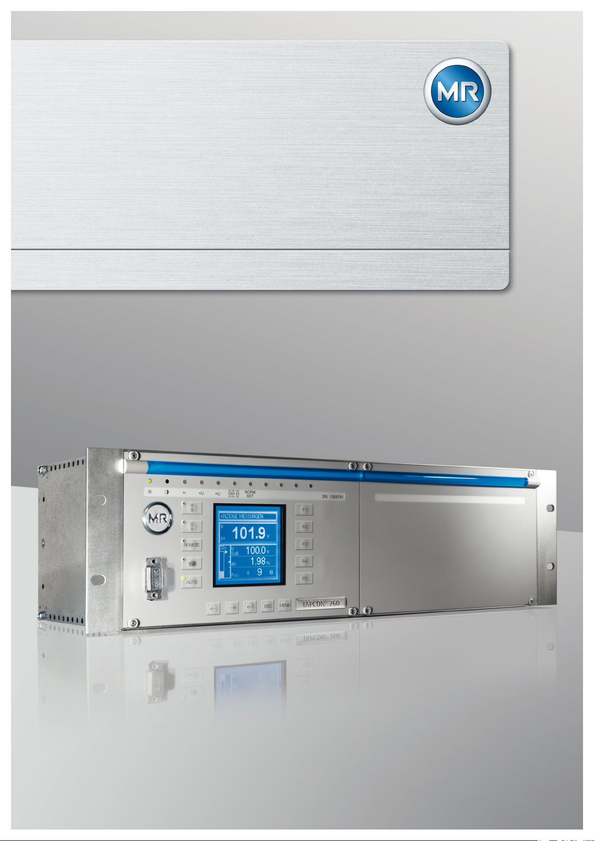
TAPCON® 260
Operating Instructions
2374092/04 EN . Bank Parallel Operation with IEC 61850
Page 2

© All rights reserved by Maschinenfabrik Reinhausen
Dissemination and reproduction of this document and use and disclosure of its content are strictly prohibited
unless expressly permitted.
Infringements will result in liability for compensation. All rights reserved in the event of the granting of patents,
utility models or designs.
The product may have been altered since this document was published.
We reserve the right to change the technical data, design and scope of supply.
Generally the information provided and agreements made when processing the individual quotations and orders
are binding.
The original operating instructions were written in German.
Page 3

Table of contents
Table of contents
1 Introduction ......................................................................................................................... 9
1.1 Manufacturer ....................................................................................................................................... 9
1.2 Subject to change without notice......................................................................................................... 9
1.3 Completeness...................................................................................................................................... 9
1.4 Supporting documents......................................................................................................................... 9
1.5 Safekeeping....................................................................................................................................... 10
1.6 Notation conventions ......................................................................................................................... 10
1.6.1 Hazard communication system ........................................................................................................................... 10
1.6.2 Information system .............................................................................................................................................. 11
1.6.3 Typographic conventions .................................................................................................................................... 11
2 Safety ................................................................................................................................. 12
2.1 General safety information ................................................................................................................ 12
2.2 Appropriate use ................................................................................................................................. 12
2.3 Inappropriate use............................................................................................................................... 12
2.4 Personnel qualification ...................................................................................................................... 13
2.5 Operator's duty of care ...................................................................................................................... 13
3 Product description .......................................................................................................... 14
3.1 Scope of delivery ............................................................................................................................... 14
3.2 Function description of the voltage regulation ................................................................................... 14
3.3 Performance features ........................................................................................................................ 15
3.4 Operating modes ............................................................................................................................... 15
3.5 Hardware ........................................................................................................................................... 16
3.5.1 Name plate .......................................................................................................................................................... 17
3.5.2 Operating controls ............................................................................................................................................... 17
3.5.3 Display elements ................................................................................................................................................. 18
3.5.4 Serial interface .................................................................................................................................................... 21
3.5.5 Assemblies .......................................................................................................................................................... 21
4 Mounting ............................................................................................................................ 30
4.1 Preparation ........................................................................................................................................ 30
4.2 Mounting device ................................................................................................................................ 30
4.3 Connecting device ............................................................................................................................. 31
4.3.1 Cable recommendation ....................................................................................................................................... 31
Maschinenfabrik Reinhausen 2014 32374092/04 EN TAPCON® 260
Page 4

Table of contents
4.3.2 Information about laying fiber-optic cable............................................................................................................ 33
4.3.3 Electromagnetic compatibility.............................................................................................................................. 33
4.3.4 Connecting cables to the system periphery ........................................................................................................ 37
4.3.5 Wiring device....................................................................................................................................................... 37
4.3.6 Checking functional reliability .............................................................................................................................. 38
5 Commissioning ................................................................................................................. 39
5.1 Setting the display contrast ............................................................................................................... 39
5.2 Setting parameters ............................................................................................................................ 39
5.2.1 Setting the language ........................................................................................................................................... 40
5.2.2 Setting date and time .......................................................................................................................................... 40
5.2.3 Setting further parameters................................................................................................................................... 41
5.3 Function tests .................................................................................................................................... 42
5.3.1 Checking control functions .................................................................................................................................. 43
5.3.2 Checking additional functions.............................................................................................................................. 44
5.3.3 Checking parallel operation of several banks of transformers ............................................................................ 47
6 Functions and settings..................................................................................................... 52
6.1 Key lock ............................................................................................................................................. 52
6.2 Carrying out tap-change operation manually..................................................................................... 52
6.3 General.............................................................................................................................................. 52
6.3.1 Setting device ID ................................................................................................................................................. 53
6.3.2 Setting the baud rate ........................................................................................................................................... 53
6.3.3 Setting the voltage display kV/V.......................................................................................................................... 54
6.3.4 Setting current display unit .................................................................................................................................. 54
6.3.5 Setting the switching pulse time .......................................................................................................................... 54
6.3.6 Configuring control inputs IO1-X1:33/31 ............................................................................................................. 56
6.3.7 Configuring output relays IO1-X1:25/26 and IO1-X1:23/24 ................................................................................ 57
6.3.8 Dimming display .................................................................................................................................................. 58
6.3.9 Setting motor runtime monitoring ........................................................................................................................ 59
6.3.10 Swapping tapping direction ................................................................................................................................. 61
6.4 NORMset........................................................................................................................................... 61
6.5 Control parameters............................................................................................................................ 63
6.5.1 Setting desired value 1...3................................................................................................................................... 65
6.5.2 Bandwidth............................................................................................................................................................ 66
6.5.3 Setting delay time T1........................................................................................................................................... 66
6.5.4 Setting control response T1 ................................................................................................................................ 67
Maschinenfabrik Reinhausen 20144 2374092/04 ENTAPCON® 260
Page 5

Table of contents
6.5.5 Setting delay time T2........................................................................................................................................... 68
6.6 Limit values........................................................................................................................................ 68
6.6.1 Activating/deactivating absolute or relative limit values ...................................................................................... 69
6.6.2 Setting undervoltage monitoring V< .................................................................................................................... 69
6.6.3 Setting overvoltage monitoring V> ...................................................................................................................... 72
6.6.4 Setting overcurrent monitoring I> ........................................................................................................................ 74
6.6.5 Activating/deactivating function monitoring ......................................................................................................... 75
6.7 Compensation ................................................................................................................................... 75
6.7.1 R&X compensation.............................................................................................................................................. 75
6.7.2 Z compensation................................................................................................................................................... 78
6.8 Cross-monitoring ............................................................................................................................... 79
6.8.1 Setting desired value for regulator 2 ................................................................................................................... 80
6.8.2 Setting undervoltage limit value V< for regulator 2.............................................................................................. 81
6.8.3 Setting overvoltage limit value V> for regulator 2................................................................................................ 82
6.8.4 Setting delay time for error message .................................................................................................................. 83
6.8.5 Setting transformer for regulator 2 ...................................................................................................................... 83
6.9 Transformer data ............................................................................................................................... 84
6.9.1 Setting the primary transformer voltage .............................................................................................................. 85
6.9.2 Setting the secondary transformer voltage.......................................................................................................... 85
6.9.3 Setting primary transformer current..................................................................................................................... 86
6.9.4 Setting the current transformer connection ......................................................................................................... 87
6.9.5 Setting the phase difference for the current transformer/voltage transformer..................................................... 87
6.10 Parallel operation of several banks of transformers .......................................................................... 91
6.10.1 Assigning CAN bus address................................................................................................................................ 91
6.10.2 Selecting parallel operation method .................................................................................................................... 92
6.10.3 Selecting parallel operation control ..................................................................................................................... 95
6.10.4 Setting delay time for parallel operation error messages .................................................................................... 95
6.10.5 Deactivating parallel operation ............................................................................................................................ 96
6.11 Analog tap position capture (optional) ............................................................................................... 96
6.11.1 Setting lower limit value....................................................................................................................................... 96
6.11.2 Setting upper limit value ...................................................................................................................................... 97
6.12 LED selection .................................................................................................................................... 98
6.13 Measuring transducer function ........................................................................................................ 100
6.13.1 Linking measured value with output .................................................................................................................. 100
6.13.2 Assigning minimum physical parameter............................................................................................................ 100
6.13.3 Assigning maximum physical parameter........................................................................................................... 101
Maschinenfabrik Reinhausen 2014 52374092/04 EN TAPCON® 260
Page 6

Table of contents
6.13.4 Assigning minimum absolute value ................................................................................................................... 101
6.13.5 Assigning maximum absolute value .................................................................................................................. 102
6.14 Memory (optional)............................................................................................................................ 102
6.14.1 Setting undervoltage threshold.......................................................................................................................... 103
6.14.2 Setting overvoltage threshold............................................................................................................................ 104
6.14.3 Setting time difference of average value interval .............................................................................................. 105
6.14.4 Setting event memory size ................................................................................................................................ 106
6.14.5 Time plotter ....................................................................................................................................................... 109
6.15 Communication interface SID .......................................................................................................... 115
6.15.1 Assigning a network mask................................................................................................................................. 115
6.15.2 Assigning network address ............................................................................................................................... 115
6.15.3 Entering the time server address ...................................................................................................................... 116
6.15.4 Entering gateway............................................................................................................................................... 116
6.15.5 Entering IED name ............................................................................................................................................ 117
6.16 Communication interface CIC2 (optional)........................................................................................ 117
6.16.1 Selecting the communication port ..................................................................................................................... 117
6.16.2 Selecting communication baud rate .................................................................................................................. 118
6.16.3 Assigning network address ............................................................................................................................... 118
6.16.4 Assigning the TCP port ..................................................................................................................................... 119
6.16.5 Setting the transmission delay time for the RS485 interface............................................................................. 119
6.17 Displaying information about device ................................................................................................ 120
6.17.1 Displaying the info screen ................................................................................................................................. 120
6.17.2 Displaying measured values ............................................................................................................................. 120
6.17.3 Carrying out LED test ........................................................................................................................................ 121
6.17.4 Displaying input/output status ........................................................................................................................... 121
6.17.5 Displaying UC card status ................................................................................................................................. 122
6.17.6 Resetting parameters ........................................................................................................................................ 123
6.17.7 Displaying real-time clock.................................................................................................................................. 123
6.17.8 Displaying parallel operation ............................................................................................................................. 123
6.17.9 Displaying data on CAN bus ............................................................................................................................. 123
6.17.10 Displaying measured value memory ................................................................................................................. 125
6.17.11 Displaying peak memory ................................................................................................................................... 125
6.17.12 Displaying CIC card SCADA information .......................................................................................................... 126
6.17.13 Displaying upcoming messages........................................................................................................................ 126
7 Control system protocol................................................................................................. 127
7.1 Protocol specification....................................................................................................................... 127
Maschinenfabrik Reinhausen 20146 2374092/04 ENTAPCON® 260
Page 7

Table of contents
7.1.1 Downloading ICD file......................................................................................................................................... 127
7.2 Data points ...................................................................................................................................... 128
7.2.1 LPHD - Physical device..................................................................................................................................... 128
7.2.2 LLN0 - Logical node .......................................................................................................................................... 129
7.2.3 ATCC1 - Automatic tap changer controller........................................................................................................ 129
7.2.4 YLTC1 ............................................................................................................................................................... 131
7.2.5 YLTC2 ............................................................................................................................................................... 132
7.2.6 YLTC3 ............................................................................................................................................................... 132
7.2.7 GGIO1 - Generic process I/O............................................................................................................................ 133
7.2.8 GGIO2 - Generic process I/O............................................................................................................................ 134
7.2.9 GGIO3 - Generic process I/O............................................................................................................................ 135
7.2.10 GGIO4 - Generic process I/O............................................................................................................................ 135
7.2.11 GGIO7 - Generic process I/O............................................................................................................................ 136
8 Maintenance and care..................................................................................................... 138
9 Fault elimination.............................................................................................................. 139
9.1 General faults .................................................................................................................................. 139
9.2 No regulation in AUTO mode .......................................................................................................... 139
9.3 Man-machine interface .................................................................................................................... 140
9.4 Incorrect measured values .............................................................................................................. 140
9.5 Parallel operation faults ................................................................................................................... 141
9.6 Tap position capture incorrect ......................................................................................................... 142
9.7 Other faults ...................................................................................................................................... 142
10 Messages......................................................................................................................... 144
10.1 Signal inputs .................................................................................................................................... 144
10.2 Signal outputs .................................................................................................................................. 144
10.3 Event messages .............................................................................................................................. 145
11 Disposal ........................................................................................................................... 147
12 Overview of parameters ................................................................................................. 148
13 Technical data ................................................................................................................. 152
13.1 Indicator elements ........................................................................................................................... 152
13.2 Power supply ................................................................................................................................... 152
13.3 Voltage measurement and current measurement ........................................................................... 154
13.4 Digital inputs and outputs ................................................................................................................ 155
Maschinenfabrik Reinhausen 2014 72374092/04 EN TAPCON® 260
Page 8

Table of contents
13.5 Analog inputs and outputs ............................................................................................................... 156
13.6 Control voltage supply (optional) ..................................................................................................... 156
13.7 Central processing unit .................................................................................................................... 158
13.8 System networking .......................................................................................................................... 158
13.9 Dimensions and weight ................................................................................................................... 159
13.10 Ambient conditions .......................................................................................................................... 161
13.11 Tests................................................................................................................................................ 161
13.11.1 Electrical safety ................................................................................................................................................. 161
13.11.2 EMC tests.......................................................................................................................................................... 161
13.11.3 Environmental durability tests ........................................................................................................................... 161
Glossary........................................................................................................................... 163
List of key words............................................................................................................. 164
Maschinenfabrik Reinhausen 20148 2374092/04 ENTAPCON® 260
Page 9

1 Introduction
Introduction
1
This technical file contains detailed descriptions on the safe and proper installation, connection, commissioning and monitoring of the product.
It also includes safety instructions and general information about the product.
This technical file is intended solely for specially trained and authorized personnel.
Manufacturer
1.1
The product is manufactured by:
Maschinenfabrik Reinhausen GmbH
Falkensteinstraße 8
93059 Regensburg, Germany
Tel.: (+49) 9 41/40 90-0
Fax: (+49) 9 41/40 90-7001
E-mail: sales@reinhausen.com
Further information on the product and copies of this technical file are available from this address if required.
Subject to change without notice
1.2
The information contained in this technical file comprises the technical specifications approved at the time of printing. Significant modifications will be included in a new edition of the technical file.
The document number and version number of this technical file are shown in
the footer.
Completeness
1.3
This technical file is incomplete without the supporting documentation.
Supporting documents
1.4
The following documents apply to this product:
▪ Operating instructions
▪ Connection diagrams
Also observe generally valid legislation, standards, guidelines and specifications on accident prevention and environmental protection in the respective
country of use.
Maschinenfabrik Reinhausen 2014 92374092/04 EN TAPCON® 260
Page 10
1 Introduction
Safekeeping
1.5
This technical file and all supporting documents must be kept ready at hand
and accessible for future use at all times.
Notation conventions
1.6
This section contains an overview of the symbols and textual emphasis
used.
WARNING
1.6.1
1.6.1.1
1.6.1.2
Hazard communication system
Warnings in this technical file are displayed as follows.
Warning relating to section
Warnings relating to sections refer to entire chapters or sections, sub-sections or several paragraphs within this technical file. Warnings relating to
sections use the following format:
Type and source of danger
Consequences
► Action
► Action
Embedded warning information
Embedded warnings refer to a particular part within a section. These warnings apply to smaller units of information than the warnings relating to sections. Embedded warnings use the following format:
DANGER! Instruction for avoiding a dangerous situation.
1.6.1.3
Signal words and pictograms
The following signal words are used:
Signal
word
DANGER Indicates a hazardous situation which, if not avoided, will
WARNING Indicates a hazardous situation which, if not avoided, could
CAUTION Indicates a hazardous situation which, if not avoided, could
NOTICE Indicates measures to be taken to prevent damage to
Table 1: Signal words in warning notices
Meaning
result in death or serious injury.
result in death or serious injury.
result in injury.
property.
Maschinenfabrik Reinhausen 201410 2374092/04 ENTAPCON® 260
Page 11
1 Introduction
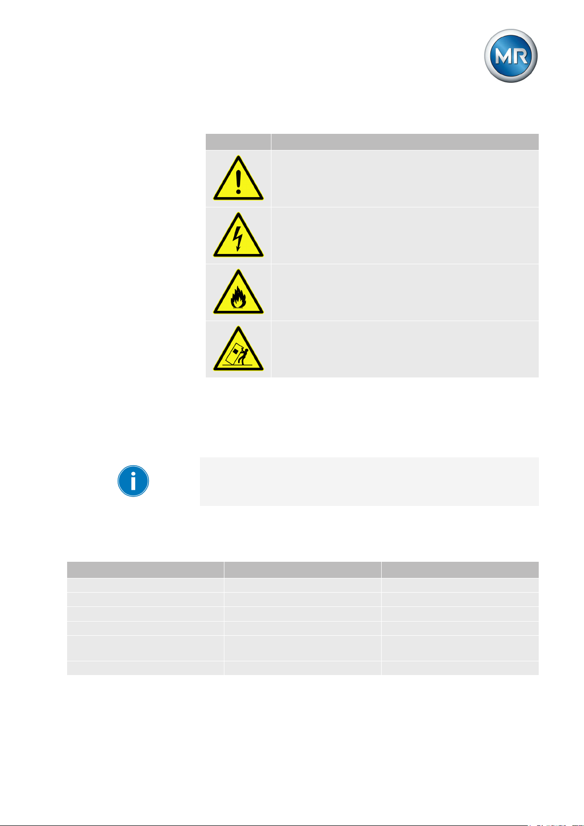
Pictograms warn of dangers:
Pictogram Meaning
Warning of a danger point
Warning of dangerous electrical voltage
Warning of combustible substances
Warning of danger of tipping
Table 2: Pictograms used in warning notices
1.6.2
1.6.3
Typographic convention Purpose Example
UPPERCASE Operating controls, switches ON/OFF
[Brackets] PC keyboard [Ctrl] + [Alt]
Bold Software operating controls Press Continue button
…>…>… Menu paths Parameter > Control parameter
Italics System messages, error mes-
[► Number of pages]. Cross reference [► 41].
Table 3: Typographic conventions
Information system
Information is designed to simplify and improve understanding of particular
procedures. In this technical file it is laid out as follows:
Important information.
Typographic conventions
The following typographic conventions are used in this technical file:
Function monitoring alarm trig-
sages, signals
gered
Maschinenfabrik Reinhausen 2014 112374092/04 EN TAPCON® 260
Page 12

Safety
2
General safety information
2.1
The technical file contains detailed descriptions on the safe and proper installation, connection, commissioning and monitoring of the product.
▪ Read this technical file through carefully to familiarize yourself with the
product.
▪ Particular attention should be paid to the information given in this chap-
ter.
Appropriate use
2.2
The product and associated equipment and special tools supplied with it
comply with the relevant legislation, regulations and standards, particularly
health and safety requirements, applicable at the time of delivery.
If used as intended and in compliance with the specified requirements and
conditions in this technical file as well as the warning notices in this technical
file and attached to the product, then the product does not present any hazards to people, property or the environment. This applies throughout the
product's entire life, from delivery through installation and operation to disassembly and disposal.
2 Safety
The operational quality assurance system ensures a consistently high quality
standard, particularly in regard to the observance of health and safety requirements.
The following is considered appropriate use
▪ The product must be operated in accordance with this technical file and
the agreed delivery conditions and technical data
▪ The equipment and special tools supplied must be used solely for the in-
tended purpose and in accordance with the specifications of this technical file
Inappropriate use
2.3
Use is considered to be inappropriate if the product is used other than as described in the Appropriate use section. Please also note the following:
▪ Risk of explosion and fire from highly flammable or explosive gases, va-
pors, or dusts. Do not operate product in areas at risk of explosion.
▪ Unauthorized or inappropriate changes to the product may lead to per-
sonal injury, material damage, and operational faults. Only modify product following discussion with Maschinenfabrik Reinhausen GmbH.
Maschinenfabrik Reinhausen 201412 2374092/04 ENTAPCON® 260
Page 13

2 Safety
Personnel qualification
2.4
The product is designed solely for use in electrical energy systems and facilities operated by appropriately trained staff. This staff comprises people who
are familiar with the installation, assembly, commissioning and operation of
such products.
Operator's duty of care
2.5
To prevent accidents, disruptions and damage as well as unacceptable adverse effects on the environment, those responsible for transport, installation, operation, maintenance and disposal of the product or parts of the product must ensure the following:
▪ All warning and hazard notices are complied with.
▪ Personnel are instructed regularly in all relevant aspects of operational
safety, the operating instructions and particularly the safety instructions
contained therein.
▪ Regulations and operating instructions for safe working as well as the
relevant instructions for staff procedures in the case of accidents and
fires are kept on hand at all times and are displayed in the workplace
where applicable.
▪ The product is only used when in a sound operational condition and
safety equipment in particular is checked regularly for operational reliability.
▪ Only replacement parts, lubricants and auxiliary materials which are au-
thorized by the manufacturer are used.
▪ The specified operating conditions and requirements of the installation
location are complied with.
▪ All necessary devices and personal protective equipment for the specific
activity are made available.
▪ The prescribed maintenance intervals and the relevant regulations are
complied with.
▪ Installation, electrical connection and commissioning of the product may
only be carried out by qualified and trained personnel in accordance
with this technical file.
▪ The operator must ensure appropriate use of the product.
Maschinenfabrik Reinhausen 2014 132374092/04 EN TAPCON® 260
Page 14
3 Product description
Product description
3
This chapter contains an overview of the design and function of the product.
Scope of delivery
3.1
The following items are included in the delivery:
▪ TAPCON® 260
▪ CD MR-Suite (contains the TAPCON®-trol program)
▪ Technical files
▪ Serial cable RS232
▪ USB adapter with installation CD (optional)
Please note the following:
▪ Check the shipment for completeness on the basis of the shipping docu-
ments.
▪ Store the parts in a dry place until installation.
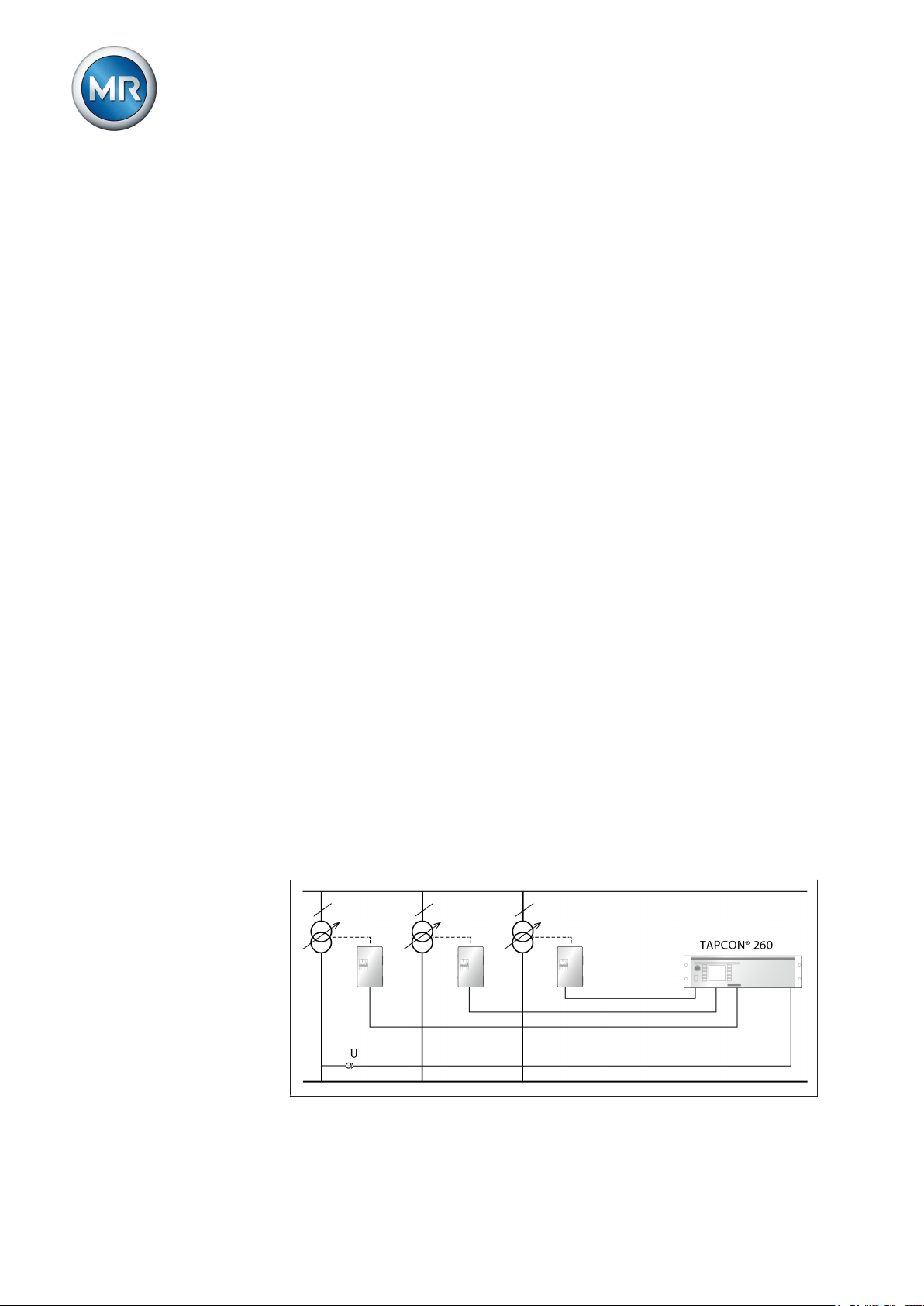
Function description of the voltage regulation
3.2
The TAPCON® 260 serves to keep constant the output voltage of a bank of
transformers with on-load tap-changers. The bank of transformers consists
of 3 single-phase transformers, each with an on-load tap-changer and motor-drive unit.
The TAPCON® 260 compares the measured voltage of the bank of transformers (U
tween U
) with a defined reference voltage (U
actual
actual
and U
is the control deviation (dU).
desired
). The difference be-
desired
The TAPCON® 260 parameters can be optimally adjusted to the line voltage
response to achieve a balanced control response with a small number of
tap-change operations by the on-load tap-changer.
The following diagram shows an overview of voltage regulation.
Figure 1: Overview of voltage regulation of a bank of transformers
Maschinenfabrik Reinhausen 201414 2374092/04 ENTAPCON® 260
Page 15

3 Product description
Performance features
3.3
The TAPCON® 260 is responsible for controlling tapped transformers in a
bank of transformers.
Apart from control tasks, the TAPCON® 260 provides additional functions
such as:
▪ Integrated protective functions:
– Undervoltage blocking and overvoltage blocking
– Overvoltage detection with high-speed return
▪ Compensation for voltage drops on the line (line drop compensation)
▪ Compensation for voltage fluctuations in the meshed grid (Z compensa-
tion)
▪ Digital inputs and outputs can be individually programmed on-site by the
user
▪ Additional indicators using LEDs outside the display
▪ Display of all measured values such as voltage, current, active power,
apparent power or reactive power, power factor (cos φ)
▪ Selection of 3 different desired values
▪ When ordering you can choose between tap position capture:
– using analog signal 4…20 mA
– using analog signal via resistor contact series
– using digital signal via BCD code
▪ Parallel operation of up to 16 banks of transformers in 2 groups using
the following methods:
– Master/Follower
– Circulating reactive current minimization
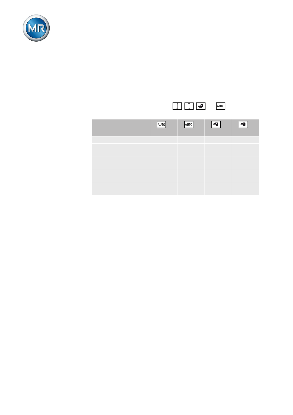
Operating modes
3.4
The device can be operated in the following operating modes:
Auto mode (AUTO)
In auto mode, the voltage is automatically controlled in accordance with the
set parameters. You cannot change further device settings in auto mode.
There is no active management by a higher level control system in this operating mode.
Manual mode (MANUAL)
In manual mode, there is no automatic control. The motor-drive unit can be
controlled via the device's operating panel. You can change the device settings.
Maschinenfabrik Reinhausen 2014 152374092/04 EN TAPCON® 260
Page 16
3 Product description
Local mode (LOCAL)
There is no active management by a superordinate control system in this operating mode.
Remote mode (REMOTE)
In remote mode, you can perform commands using an external control level.
In this case, manual operation of the , , and keys is disa-
bled.
Automatic regulation Yes Yes No No
Tap-change operation
using operating controls
Tap-change operation
using inputs
Tap-change operation
using SCADA*
Value adjustment using
SCADA*
Table 4: Overview of operating modes
*) Optional when connecting TAPCON® to a control system (SCADA)
Hardware
3.5
The individual assemblies are fitted in a standardized 19-inch plug-in housing. The front panels of the assemblies are secured to the plug-in housing at
the top and bottom. An IEC 60603-2 plug connector provides the electrical
connection.
The assemblies are connected to one another via a data bus and direct current (DC) supply. This allows for an upgrade with additional plug-in modules
and extension cards at a later date.
+
LOCAL +REMOTE +LOCAL +REMOTE
No No Yes No
No No No Yes
No No No Yes
No Yes No Yes
Maschinenfabrik Reinhausen 201416 2374092/04 ENTAPCON® 260
Page 17
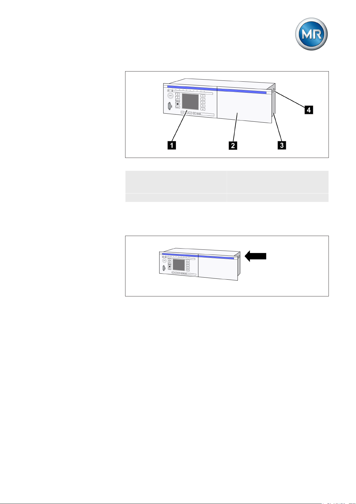
3 Product description
Figure 2: Front view
3.5.1
3.5.2
1 Operating panel with display
and LEDs
2 Rack for optional expansions 4 Name plate
3 19-inch plug-in housing (in ac-
cordance with DIN 41494 Part
5)
Name plate
The name plate is on the outside of the device:
Figure 3: Name plate
Operating controls
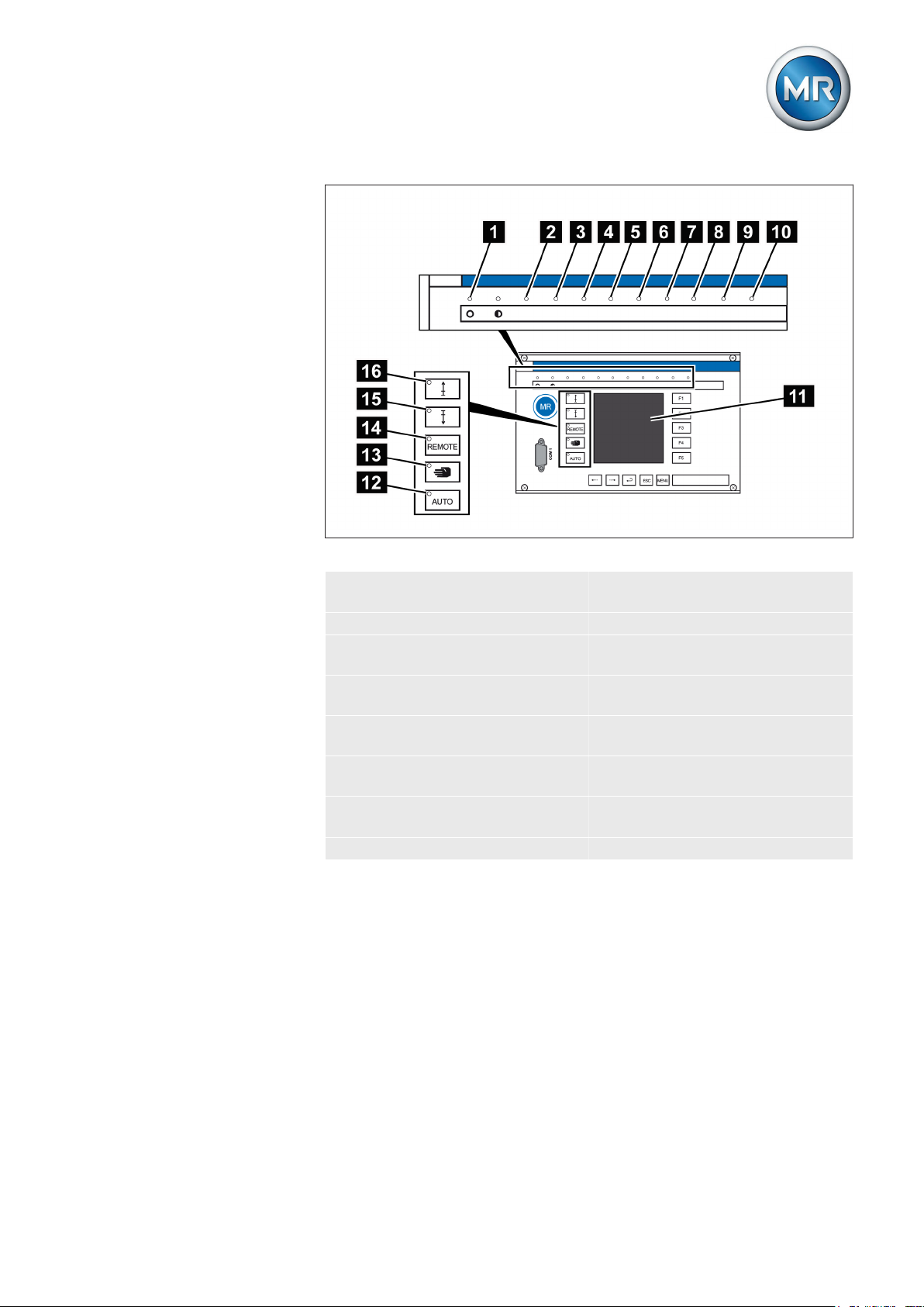
The device has 15 pushbuttons. The illustration below is an overview of all
the device's operating controls .
Maschinenfabrik Reinhausen 2014 172374092/04 EN TAPCON® 260
Page 18
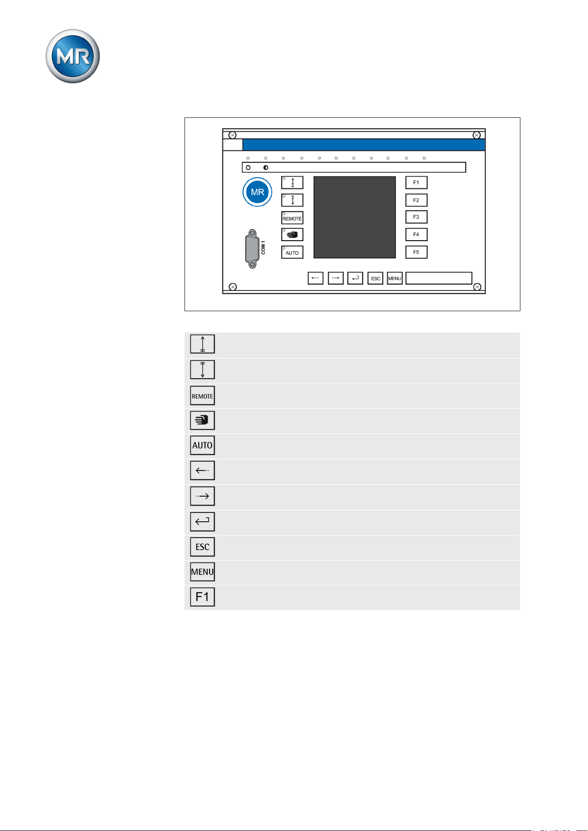
Figure 4: Operating controls
RAISE key: Sends control command for raise tap-change to the
motor-drive unit in manual mode. See also [► 52].
LOWER key: Sends control command for lower tap-change to the
motor-drive unit in manual mode. See also [► 52].
REMOTE key: Activate/deactivate "Remote" operating mode.
3 Product description
3.5.3
MANUAL key: Activate "Manual" operating mode.
AUTO key: Activate "Auto mode" operating mode.
PREV key: Change measured value display and switch to previ-
ous parameters.
NEXT key: Change measured value display and switch to next
parameters.
ENTER key: Confirm selection and save modified parameters.
ESC key: Escape current menu and select previous menu levels.
MENU key: Select main menu.
F1 to F5 function keys: Select functions displayed on the screen.
Display elements
The device has a graphics display and 15 LEDs, which indicate the various
operating statuses or events.
Maschinenfabrik Reinhausen 201418 2374092/04 ENTAPCON® 260
Page 19
3 Product description
Figure 5: Display elements
1 Operating status LED, green 9 Motor protective switch LED,
yellow
2 Overcurrent blocking LED, red 10 Master LED, green/yellow/red
3 Undervoltage blocking LED,
11 Graphics display
red
4 Overvoltage blocking LED,
12 Auto mode active LED
red
5 Parallel operation active LED,
13 Manual mode active LED
green
6 NORMset active LED , green 14 Remote operating mode ac-
tive LED
7 Parallel operation fault LED,
15 Lower tap-change active LED
yellow
8 Tap difference LED, yellow 16 Raise tap-change active LED
Maschinenfabrik Reinhausen 2014 192374092/04 EN TAPCON® 260
Page 20
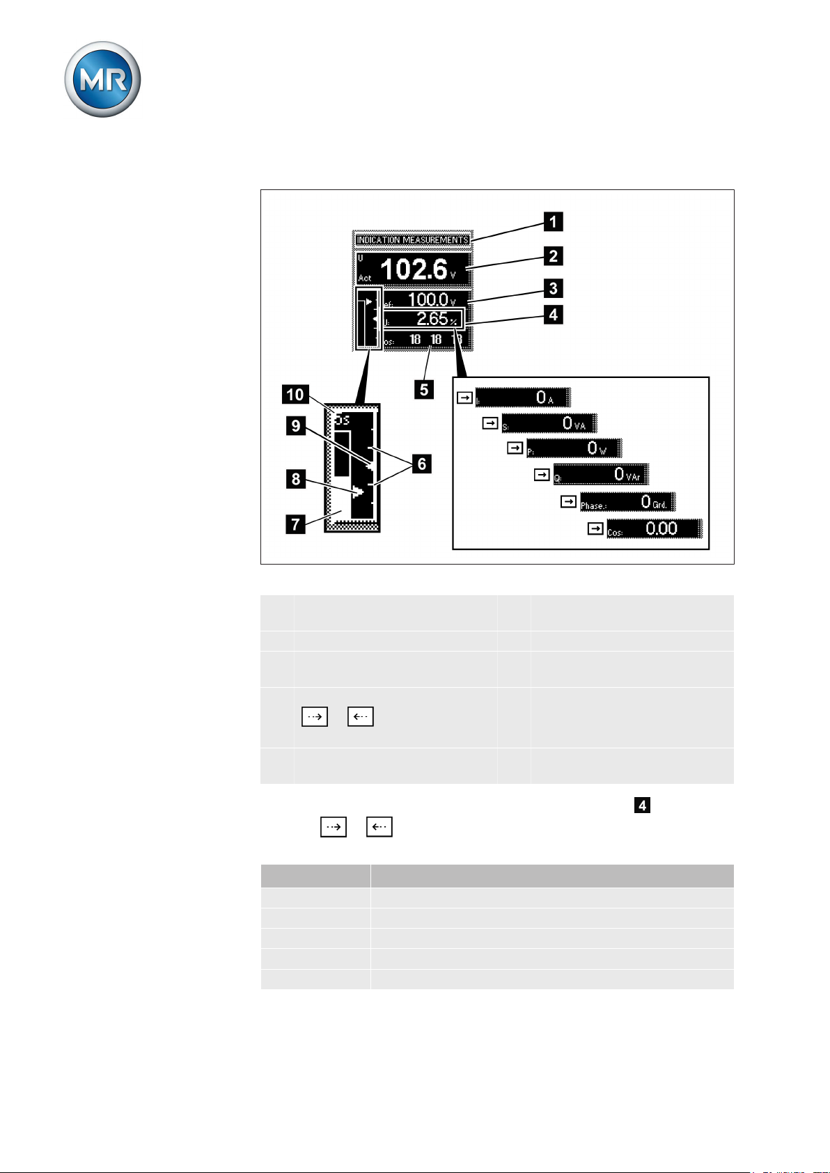
Display
3 Product description
Other measured values
Figure 6: Display
1 Status line 6 Bandwidth (upper and lower
limit)
2 Measured voltage U
3 Reference voltage U
Act
Ref
4 Other measured values (use
or to switch between
7 Time bar for delay time T1
8 Highlighting for measured
voltage U
Act
9 Highlighting for reference volt-
age U
Ref
them)
5 Current tap position ED1,
10 Remaining delay time T1
ED2, ED3
In auto mode and manual mode the measured value display can be set
using the or keys. The following measured values can be dis-
played:
Unit Measured value
dU Control deviation
I Current
S Apparent power
P Active power
Q Reactive power
Maschinenfabrik Reinhausen 201420 2374092/04 ENTAPCON® 260
Page 21
3 Product description
Unit Measured value
Phase Phase angle
Cos Active factor: Cosine φ [phi] (output factor)
Table 5: Measured value display
Status line
3.5.4
Current messages and events are displayed in the status line . You can
find more information about messages and events in the Messages [► 144]
chapter.
Serial interface
The parameters for the device can be set using a PC. The COM 1 (RS232)
serial interface on the front panel is provided for this purpose. You can use
the connection cable supplied to establish a connection to your PC via the
RS232 or USB port (using the optional USB adapter).
TAPCON®-trol software is needed for parameterization via the serial interface. The software and the related operating instructions are contained on
the CD provided.
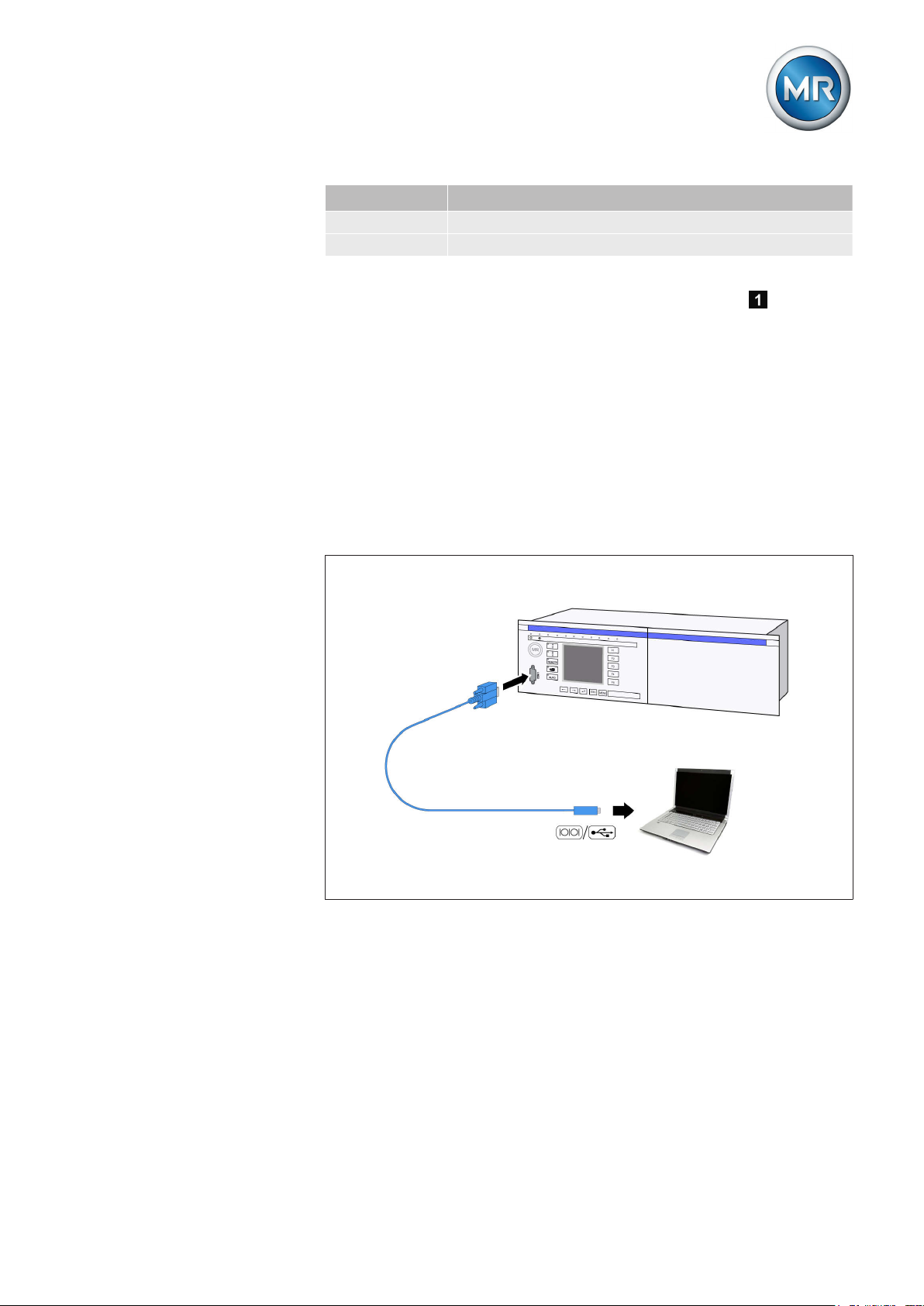
Figure 7: Device connection to a PC
3.5.5
Maschinenfabrik Reinhausen 2014 212374092/04 EN TAPCON® 260
Assemblies
Depending on configuration, the device may have various assemblies which
perform the functions required. Depending on configuration, the device may
be equipped with the following assemblies:
Page 22
3 Product description
Card Default/option Max. number
AN Option 1
AC Option 1
AD Option 1, optional with extension
module
CIC Option 2
CPU Standard 1
IO Standard 1
MI Standard 1
SU Standard 1
UC Standard 3, 4 (for SID)
Table 6: Assemblies
The functions of the assemblies are described in the following sections. You
can find more information about the assemblies in the Technical data
[► 152] section.
3.5.5.1
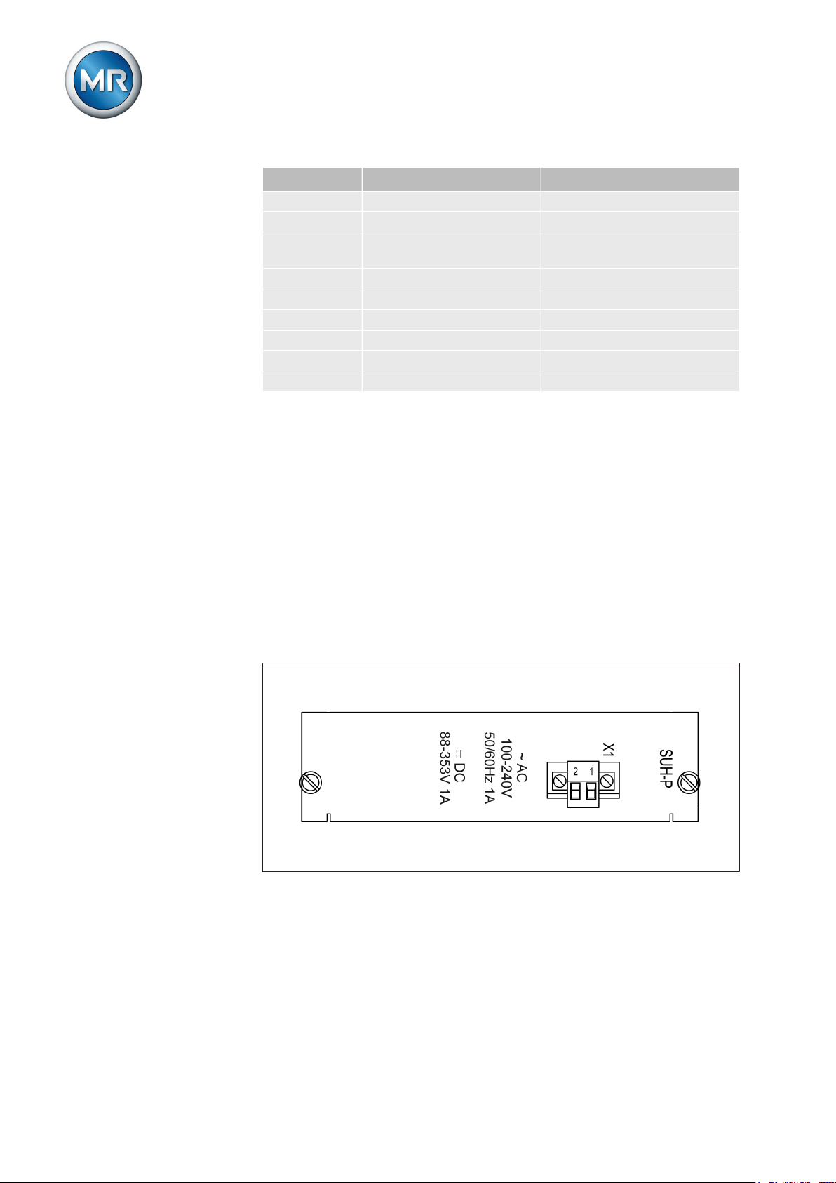
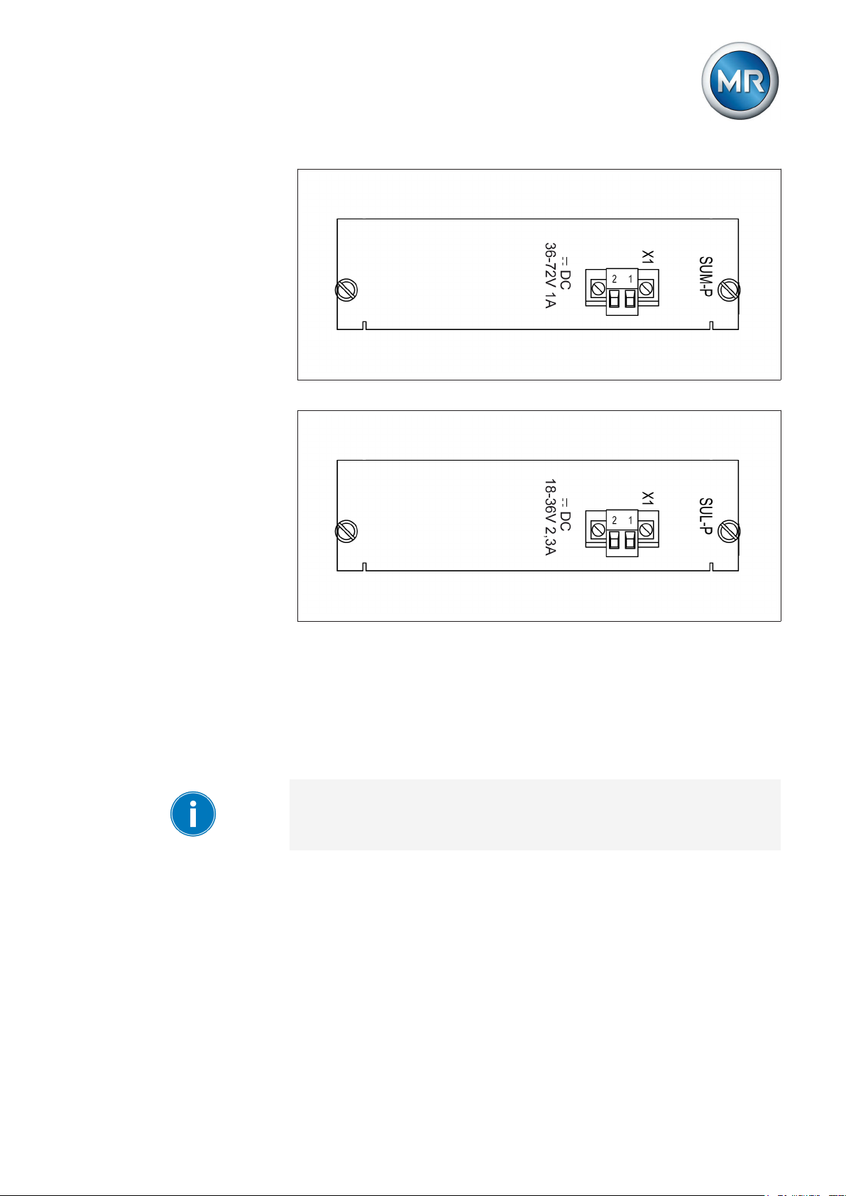
Power supply
The wide range power supply (SU card) supplies the device with power. Depending on configuration, the device is equipped with one of the following
variants:
▪ SUH-P: Rated input voltage 100...240 V AC or 88...353 V DC (input volt-
age range 88...264 V AC, 88...353 V DC)
▪ SUM-P: Input voltage 36...72 V DC
▪ SUL-P: Input voltage 18...36 V DC
Figure 8: SUH-P card
Maschinenfabrik Reinhausen 201422 2374092/04 ENTAPCON® 260
Page 23
3 Product description
Figure 9: SUM-P card
3.5.5.2
Figure 10: SUL-P card
Voltage measurement and current measurement
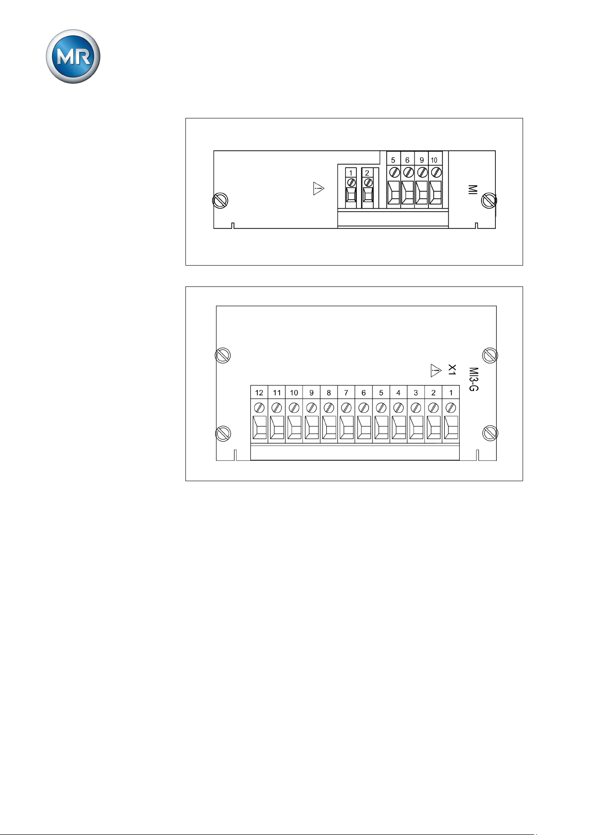
To measure voltage and current, the device can be equipped with the assembly MI or MI3-G:
▪ MI: 1-phase measurement of voltage and current
▪ MI3-G: 3-phase measurement of voltage and current
Only connect the MI card to one current transformer, otherwise the current
measurement will not work.
Maschinenfabrik Reinhausen 2014 232374092/04 EN TAPCON® 260
Page 24
3 Product description
Figure 11: MI-1 card
3.5.5.3
Figure 12: MI3G card
Digital inputs and outputs
To record and output digital signals, the device may be equipped with the
following assemblies:
▪ IO card
▪ UC card
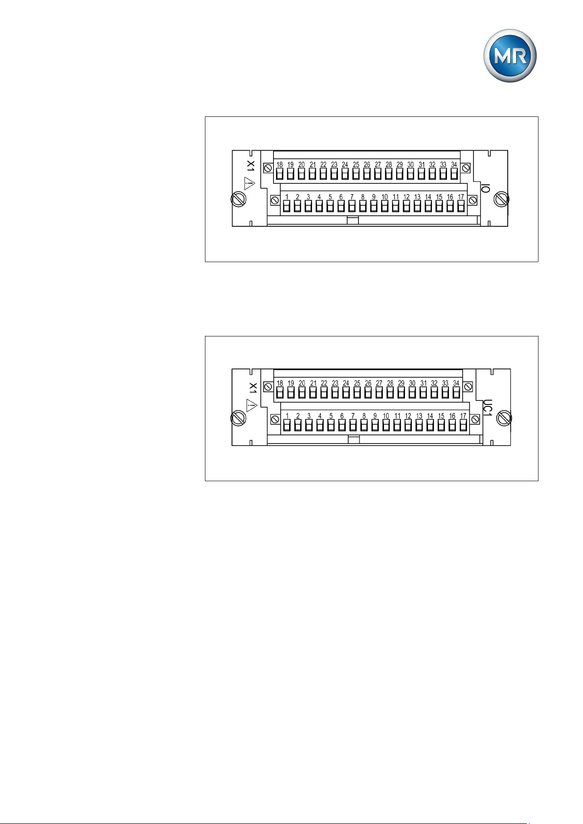
IO card
The IO card contains 9 digital inputs and 8 digital potential-free outputs. 5
outputs take the form of change-over contacts.
Maschinenfabrik Reinhausen 201424 2374092/04 ENTAPCON® 260
Page 25
3 Product description
Figure 13: IO card
UC card
The UC card contains 10 digital inputs and 10 digital potential-free outputs.
The device can be equipped with several UC cards (UC1, UC2...).
3.5.5.4
Figure 14: UC1 card
Analog inputs and outputs
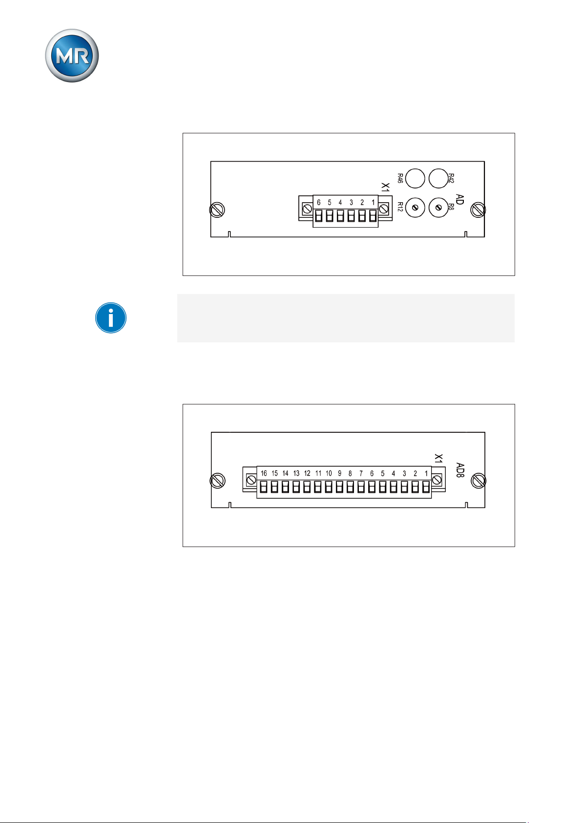
To record and output analog signals, the device may be equipped with the
following assemblies:
▪ AD card
▪ AD8 card
▪ AN card
AD card
The analog input card has 1 input or with an extension card 2 inputs that can
record the following analog signals:
▪ 0...±10 V
▪ 0...±10 mA
▪ 0...±20 mA
Maschinenfabrik Reinhausen 2014 252374092/04 EN TAPCON® 260
Page 26
3 Product description
▪ Resistance measurement (50...2 000 Ω)
Figure 15: AD card
Only use the R8/R12 and R42/R46 rotary potentiometers to calibrate the resistance measurement.
AD8 card
The analog input card has 8 inputs that can record the analog signals
(4...20mA).
Figure 16: AD8 card
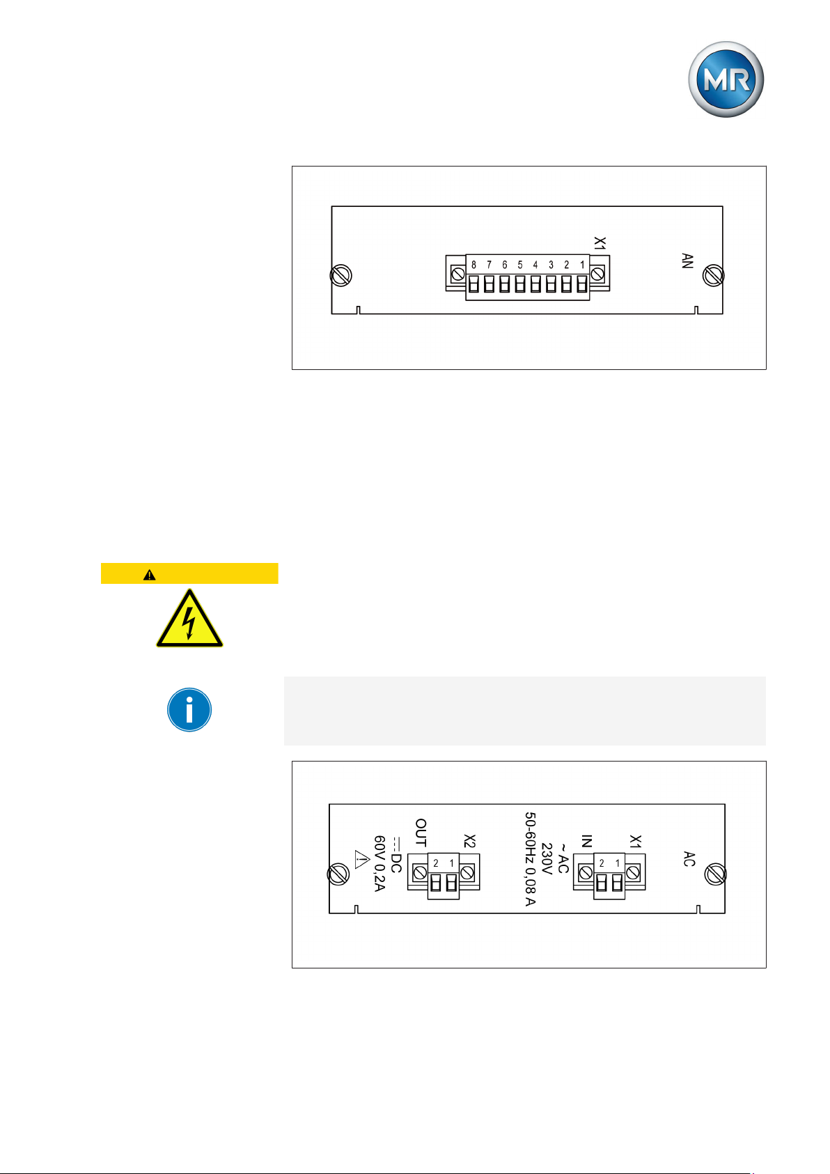
AN card
Depending on configuration, the AN card provides 2 analog outputs or with
an extension module AN1 a total of 4 analog outputs. The following signal
types are supported:
▪ 0...±20mA
▪ 0...±10mA
▪ 0...±1mA
▪ 0...±10V
Maschinenfabrik Reinhausen 201426 2374092/04 ENTAPCON® 260
Page 27
3 Product description
Figure 17: AN card
3.5.5.5
Control voltage supply
An additional non-regulated control voltage of 60 V DC can be created with
the AC card if your system does not have external DC voltage as the signal
voltage for the device's digital inputs. Depending on device configuration,
one of the following two variants can be fitted:
▪ AC230: 230 V AC input voltage
▪ AC115: 115 V AC input voltage
CAUTION
Risk of injury from increased output voltage
Slight loading of the AC card may result in the output voltage increasing to
up to 85 V DC.
► Only wire card when not energized.
The output performance of the AC card is limited. The generated DC voltage can be used only for the control inputs of the device.
Figure 18: AC230 card
Maschinenfabrik Reinhausen 2014 272374092/04 EN TAPCON® 260
Page 28

Figure 19: AC115 card
3 Product description
3.5.5.6
Central processing unit
The CPU card is the device's central computing unit. All internal device functions and the application functions, such as processing measured values,
are controlled and monitored by the CPU card.
The CPU card contains a flash memory (optional measured value memory)
as a non-volatile data storage in which the operating data such as measured
values or events are stored. An EEPROM for storing parameters and a realtime clock (RTC) for recording time are included on the CPU card.
The CPU card contains the following interfaces:
▪ RS232 system interface
▪ CAN bus
3.5.5.7
Figure 20: CPU card
1 CAN bus interface
System networking
The device is equipped with the following assemblies:
Maschinenfabrik Reinhausen 201428 2374092/04 ENTAPCON® 260
Page 29
3 Product description
CIC card
As an option, the device can be equipped with up to 2 CIC cards. The CIC
cards are used to communicate using a control system protocol or
TAPCON®-trol software (CIC2).
Figure 21: CIC card
1 RS232 6 TxD LED for transmit signal
2 RS485 7 RxD LED for receive signal
3 RJ45 (Ethernet), optional 8 Clk LED for operating mode
(flashes for 2 seconds)
4 Fiber-optic cable, optional 9 Clip for connecting cable
shield
5 Reset key
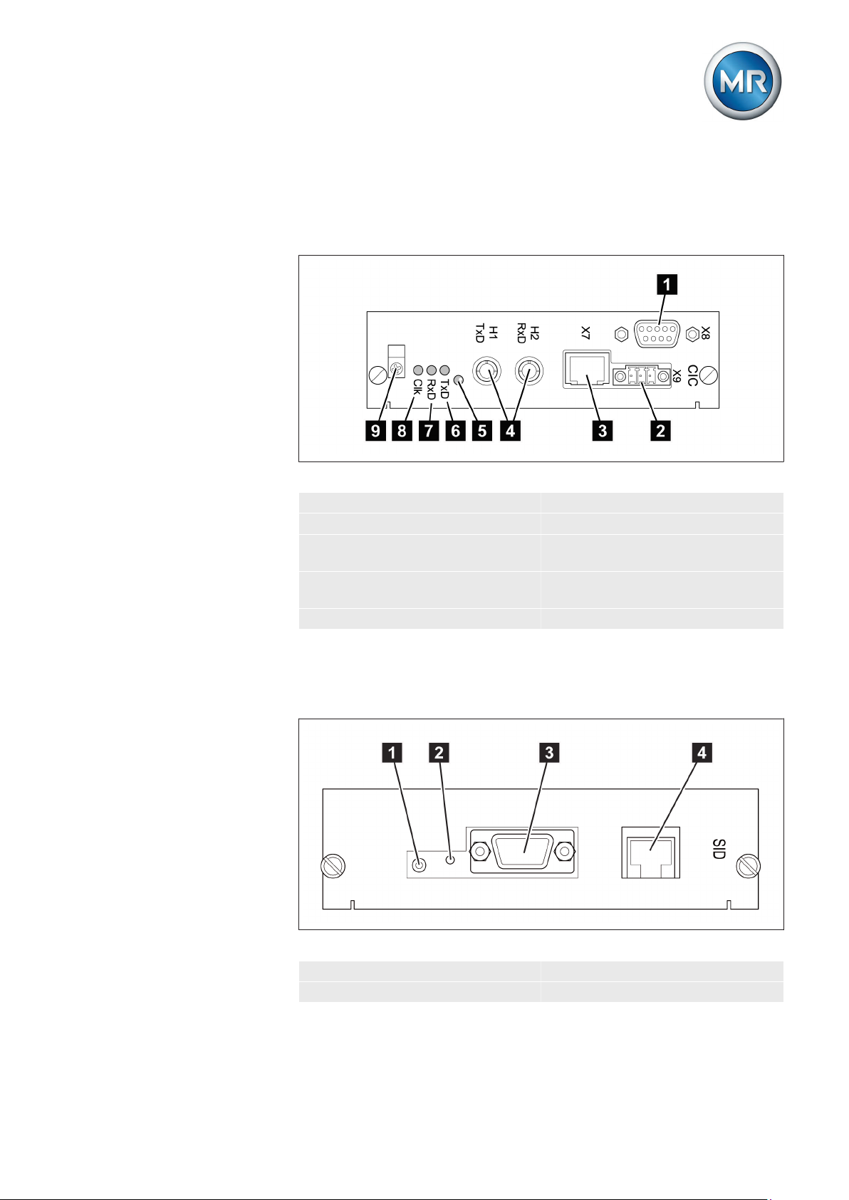
SID card
The SID interface card is used to connect the device to the control station
system (SCADA). The IEC 61850 protocol transfers the data using Ethernet.
Figure 22: SID card
1 Reset key 3 RS232 system interface
2 LED for operating status 4 RJ45 (Ethernet)
Maschinenfabrik Reinhausen 2014 292374092/04 EN TAPCON® 260
Page 30

4 Mounting
Mounting
4
This chapter describes how to correctly mount and connect the device. Note
the connection diagrams provided.
WARNING
NOTICE
Electric shock
Risk of fatal injury due to electrical voltage.
► De-energize the device and system peripherals and lock them to pre-
vent them from being switched back on.
► Do so by short-circuiting the current transformer; do not idle the current
transformer.
Electrostatic discharge
Damage to the device due to electrostatic discharge.
► Take precautionary measures to prevent the build-up of electrostatic
charges on work surfaces and personnel.
Preparation
4.1
The following tools are needed for mounting:
▪ Screwdriver for the fixing bolts (M6)
▪ Small screwdriver for connecting the signal lines and supply lines
Depending on installation site and mounting variant, you may need additional tools and corresponding attachment material (screws, nuts, washers)
which are not included in the scope of supply.
Mounting device
4.2
Depending on your order, you can mount the device in one of the following
variants:
▪ 19" frame (in accordance with DIN 41494 Part 5)
▪ 19" flush control panel frame
Below you will find a description of how to mount the device in a 19" frame.
For control panel installation or wall mounting, note the technical files supplied.
To mount the device in a 19" frame, proceed as follows:
1. Place cage nuts in the desired locations on the 19" frame, noting the
device dimensions [► 159].
Maschinenfabrik Reinhausen 201430 2374092/04 ENTAPCON® 260
Page 31

4 Mounting
2. Place device in 19" frame and screw down.
Figure 23: Example of device mounting in a 19" frame
WARNING
4.3
4.3.1
Connecting device
The following section describes how to establish the electrical connection to
the device.
Electric shock
Risk of fatal injury due to connection mistakes
► Ground the device with a protective conductor using the grounding
screw on the housing.
► Note the phase difference of the secondary terminals for the current
transformer and voltage transformer.
► Connect the output relays correctly to the motor-drive unit.
Supply the voltage via separators and ensure that current paths can be
short circuited. Fit the separator, clearly labeled, near the device's power
supply so that it is freely accessible. This will allow the device to be replaced with ease in the event of a defect.
Cable recommendation
Please note the following recommendation from Maschinenfabrik Reinhausen when wiring the device.
Excessive line capacitance can prevent the relay contacts from breaking the
contact current. In control circuits operated with alternating current, take into
account the effect of the line capacitance of long control lines on the function of the relay contacts.
Maschinenfabrik Reinhausen 2014 312374092/04 EN TAPCON® 260
Page 32

4 Mounting
Cable Card Terminal Cable type Conductor
Max. length
cross-section
Power supply SU X1:1/2 Unshielded 1.5 mm² Voltage
MI/MI1 1/2 Shielded 1.5 mm² -
measurement
Current
MI/MI1 5/6/9/10 Unshielded 4 mm² -
measurement
Relay* IO X1:1...10
Unshielded 1.5 mm² -
X1:19...26
Relay* UC X1:1...10 Unshielded 1.5 mm² Signal inputs IO X1:11...17
Shielded 1.0 mm² -
X1:27...34
Signal inputs UC X1:11...17
Shielded 1.0 mm² -
X1:27...34
CAN bus CPU 1...5 Shielded 1.0 mm² 2000 m
Table 7: Recommendation for connection cable (standard connections)
Cable Card Terminal Cable type Conductor
*) Observe line capacitance, see note above.
Max. length
cross-section
AC AC X1/2:1/2 Unshielded 1.5 mm² Analog inputs AD8 X1:1...3 Shielded 1.5 mm² 400 m (< 25 Ω/km)
Analog out-
AN/AN1 X1 Shielded 1mm² -
puts
RS-232 CIC X8 Shielded 0.25 mm² 25 m
RS-485 CIC X9 Shielded 0.75 mm² 1000 m (< 50 Ω/km)
Ethernet SID
CIC
Media con-
MC1 - Optical fiber
verter
RJ45
X7
shielded, CAT7- 100 m
- -
with MTRJST duplex
patch cable
Media converter
MC2 - Fiber-optic
cable, con-
- -
nector type:
F-ST; fiber
type: multi
mode/single
mode; wavelength:
1310 nm
Table 8: Recommendation for connection cable (optional connections)
Maschinenfabrik Reinhausen 201432 2374092/04 ENTAPCON® 260
Page 33

4 Mounting
4.3.2
4.3.3
Information about laying fiber-optic cable
To ensure the smooth transfer of data via the fiber-optic cable, you must ensure that mechanical loads are avoided when laying the fiber-optic cable and
later on during operation.
Please note the following:
▪ Radii must not fall below the minimum permissible bend radii (do not
bend fiber-optic cable).
▪ The fiber-optic cables must not be over-stretched or crushed. Observe
the permissible load values.
▪ The fiber-optic cables must not be twisted.
▪ Be aware of sharp edges which could damage the fiber-optic cable's
coating when laying or could place mechanical loading on the coating
later on.
▪ Provide a sufficient cable reserve near distributor cabinets for example.
Lay the reserve such that the fiber-optic cable is neither bent nor twisted
when tightened.
Electromagnetic compatibility
The device has been developed in accordance with applicable EMC standards. The following points must be noted in order to maintain the EMC
standards.
4.3.3.1
4.3.3.2
Wiring requirement of installation site
Note the following when selecting the installation site:
▪ The system's overvoltage protection must be effective.
▪ The system's ground connection must comply with all technical regula-
tions.
▪ Separate system parts must be joined by a potential equalization.
▪ The device and its wiring must be at least 10 m away from circuit-break-
ers, load disconnectors and busbars.
Wiring requirement of operating site
Note the following when wiring the operating site:
▪ The connection cables must be laid in metallic cable ducts with a ground
connection.
▪ Do not route lines which cause interference (for example power lines)
and lines susceptible to interference (for example signal lines) in the
same cable duct.
▪ Maintain a gap of at least 100 mm between lines causing interference
and those susceptible to interference.
Maschinenfabrik Reinhausen 2014 332374092/04 EN TAPCON® 260
Page 34

Figure 24: Recommended wiring
4 Mounting
1 Cable duct for lines causing
interference
2 Interference-causing line (e.g.
power line)
3 Cable duct for lines suscepti-
ble to interference
4 Line susceptible to interfer-
ence (e.g. signal line)
▪ Short-circuit and ground reserve lines.
▪ The device must never be connected using multi-pin collective cables.
▪ Signal lines must be routed in a shielded cable.
▪ The individual conductors (outgoing conductors/return conductors) in
the cable core must be twisted in pairs.
▪ The shield must be fully (360º) connected to the device or a nearby
ground rail.
Using "pigtails" may limit the effectiveness of the shielding. Connect closefitting shield to cover all areas.
Maschinenfabrik Reinhausen 201434 2374092/04 ENTAPCON® 260
Page 35

4 Mounting
Figure 25: Recommended connection of the shielding
4.3.3.3
1 Connection of the shielding
using a "pigtail"
2 Shielding connection covering
all areas
Wiring requirement in control cabinet
Note the following when wiring the control cabinet:
▪ The control cabinet where the device will be installed must be prepared
in accordance with EMC requirements:
– Functional division of control cabinet (physical separation)
– Constant potential equalization (all metal parts are joined)
– Line routing in accordance with EMC requirements (separation of
lines which cause interference and those susceptible to interfer-
ence)
– Optimum shielding (metal housing)
– Overvoltage protection (lightning protection)
– Collective grounding (main grounding rail)
– Cable bushings in accordance with EMC requirements
– Any contactor coils present must be interconnected
▪ The device's connection cables must be laid in close contact with the
grounded metal housing or in metallic cable ducts with a ground connection.
▪ Signal lines and power lines/switching lines must be laid in separate ca-
ble ducts.
▪ The device must be grounded at the screw provided, the protective
grounding connection, using a ground strap (cross-section min. 8 mm²).
Maschinenfabrik Reinhausen 2014 352374092/04 EN TAPCON® 260
Page 36

4 Mounting
Figure 26: Ground strap connection
4.3.3.4
NOTICE
Information about shielding the CAN bus
In order for the CAN bus to operate faultlessly, you have to connect the
shielding using one of the following variants. If you are not able to use any of
the variants detailed below, we recommend using fiber optic cables. Fiber
optic cables decouple the voltage regulators and are not sensitive to electromagnetic interferences (surge and burst).
Damage to the device
If you connect the CAN bus cable to devices with different potential, current
may flow over the shielding. This current may damage the device.
► Connect the devices to a potential compensation rail to compensate for
potential.
► If both devices have different potentials, only connect the CAN bus ca-
ble's shielding to one device.
Variant 1: The connected devices share the same potential
If the devices to be connected share the same potential, proceed as follows:
1. Connect all devices to a potential compensation rail to compensate for
the potential.
2. Connect CAN bus cable's shielding to all connected devices.
Maschinenfabrik Reinhausen 201436 2374092/04 ENTAPCON® 260
Page 37

4 Mounting
Variant 2: The connected devices have different potential
Note that the shielding is less effective with this variant.
If the devices to be connected have different potential, proceed as follows:
► Connect CAN bus cable's shielding to just one device.
Connecting shielding
Connect the CAN bus cable's shielding to the intended point on the CPU
card using the cable clips provided:
Figure 27: Securing the shielding
1 Securing the CAN bus cable's shielding
4.3.4
4.3.5
Connecting cables to the system periphery
To obtain a better overview when connecting cables, only use as many
leads as necessary.
To connect cables to the system periphery, proceed as follows:
ü Use only the specified cables for wiring. Note the cable recommendation
[► 31].
► Connect the lines to be wired to the device to the system periphery as
shown in the connection diagrams supplied.
Wiring device
To obtain a better overview when connecting cables, only use as many
leads as necessary.
Maschinenfabrik Reinhausen 2014 372374092/04 EN TAPCON® 260
Page 38

4 Mounting
4.3.6
NOTICE
To wire the device, proceed as follows:
ü Note the connection diagram.
ü Use only the specified cables for wiring. Note the cable recommendation
[► 31].
ü Wire the lines to the system periphery [► 37].
1. Strip insulation from lines and leads.
2. Crimp stranded wires with wire end sleeves.
3. Guide leads into corresponding connector terminals.
4. Fasten screws for the corresponding terminals using a screwdriver.
5. Plug connectors into the correct slots.
Checking functional reliability
To ensure that the device is wired correctly, check its functional reliability.
Damage to device and system periphery
An incorrectly connected device can lead to damages in the device and system periphery.
► Check the entire configuration before commissioning.
► Prior to commissioning, be sure to check the actual voltage and operat-
ing voltage.
Check the following:
▪ Once you have connected the device to the grid, the screen displays the
MR logo and then the operating screen.
▪ The green Operating display LED top left on the device's front panel
lights up.
The device is fully mounted and can be configured. The actions required for
this are described in the following chapter.
Maschinenfabrik Reinhausen 201438 2374092/04 ENTAPCON® 260
Page 39

5 Commissioning
Commissioning
5
You need to set several parameters and perform function tests before commissioning the device. These are described in the following sections.
NOTICE
Damage to device and system periphery
An incorrectly connected device can lead to damages in the device and system periphery.
► Check the entire configuration before commissioning.
► Prior to commissioning, be sure to check the actual voltage and operat-
ing voltage.
We recommend using a device for industrial instrumentation to record the
actual transformer voltage value in order to evaluate how the device is functioning.
Setting the display contrast
5.1
You can adjust the contrast in the display with the help of an adjustment
screw on the front of the device. To adjust the contrast, proceed as follows:
► Use a screwdriver to turn the adjustment screw on the front until the
contrast is adjusted to the desired setting.
Figure 28: Setting the display contrast
Setting parameters
5.2
To commission the device, you must set the following parameters. For more
detailed information about the parameters, refer to the respective sections.
Maschinenfabrik Reinhausen 2014 392374092/04 EN TAPCON® 260
Page 40

5 Commissioning
5.2.1
5.2.2
Setting the language
You can use this parameter to set the display language for the device. The
following languages are available:
English Italian
German Portuguese
French Russian
Spanish
To set the language, proceed as follows:
1. > Configuration > General.
ð Language
2. Press or to select the required language.
3. Press .
ð The language is set.
Setting date and time
You must set the system date and system time on the device. You must set
the date and time in the following formats:
Date Time
DD.MM.YY HH:MM:SS
Table 9: Formats
The time does not switch from daylight saving time to standard time and
back automatically. You have to change the time manually.
Time
To set the time, proceed as follows:
1. > Configuration > Continue > Memory > Press
until the desired display appears.
ð Time
2. Press to highlight a digit.
ð The desired position is highlighted and the value can be changed.
3. Press to increase the value or to reduce it.
4. Press .
ð The time is set.
Maschinenfabrik Reinhausen 201440 2374092/04 ENTAPCON® 260
Page 41

5 Commissioning
Date
To set the date, proceed as follows:
1. > Configuration > Continue > Memory > Press
until the desired display appears.
ð Date
2. Press to highlight a digit.
ð The desired position is highlighted and the value can be changed.
3. Press to increase the value or to reduce it.
4. Press .
ð The date is set.
5.2.3
Setting further parameters
Set further parameters to commission the device. More detailed information
about each of the parameters can be found in the Functions and settings
[► 52] chapter.
Setting transformer data
Set the transformer data and phase difference of the current transformer and
voltage transformer:
1. Set primary transformer voltage [► 85].
2. Set secondary transformer voltage [► 85].
3. Set primary transformer current [► 86].
4. Select current-transformer connection [► 87].
5. Select transformer circuit [► 87].
Setting NORMset
If you want to commission voltage regulation quickly, you can activate
NORMset mode. If you want to set the parameters yourself, continue with
the sections below.
► Activate NORMset and set the relevant parameters [► 61].
Setting control parameters
Set the following control parameters:
1. Set desired value 1 [► 65].
2. Set the bandwidth [► 66].
3. Set delay time T1 [► 66].
4. Switch all motor-drive units into the same tap position [► 52].
Maschinenfabrik Reinhausen 2014 412374092/04 EN TAPCON® 260
Page 42

5 Commissioning
Setting line drop compensation (optional)
If you need line drop compensation, you must set all important parameters
for this:
1. Select the LDC compensation method [► 75].
2. Set the line data for the ohmic voltage drop Ur [► 77].
3. Set the line data for the inductive voltage drop Ux [► 77].
Setting parallel operation on several banks of transformers (optional)
If you need parallel operation, you must set all important parameters for this:
1. Set the parallel operation method to the circulating reactive current
method [► 92].
2. Assign the CAN bus address [► 91].
3. Set circulating reactive current sensitivity [► 93].
4. Set circulating reactive current blocking [► 93].
Setting control system protocol (optional)
If you need a control system protocol, you must set all important parameters
for this. More detailed information about this can be found in the control system protocol description.
Setting tap position capture via analog input (optional)
If you want to capture the tap position via the analog input, you must set the
parameters required for this:
► Capture tap positions via analog input (input 1 or input 2) [► 96].
All parameters relevant to commissioning are entered. Continue with the
function tests.
Function tests
5.3
Before switching from manual mode to auto mode, Maschinenfabrik Reinhausen recommends carrying out function tests. These function tests are described in the following sections. Note the following points for all function
tests:
▪ You must ensure that the REMOTE mode is disabled before you can
control the on-load tap-changer manually in manual mode.
▪ You can only activate the on-load tap-changer manually in manual
mode using the and keys.
▪ During the function test, you must set the most important parameters.
Details on the parameters listed can be found in the Functions and settings [► 52] chapter.
Maschinenfabrik Reinhausen 201442 2374092/04 ENTAPCON® 260
Page 43

5 Commissioning
5.3.1
Checking control functions
This section describes how you can check the device's control functions:
ü Supply voltage must be present.
ü All motor-drive units must be in the same tap position.
1. Press to select manual mode.
2. Set transmission ratio for voltage transformer, current transformer and
measuring set-up.
3. Measure actual voltage and compare with the measured value displayed on the device's main screen.
4. Press key several times to display the operating values for current,
power and phase angle and compare them with values of service instruments.
5. Control all on-load tap-changers manually with the or keys and
the "ED all" selection until the measured voltage (U
sired voltage (U
) set in the next stage.
desired
6. Set desired value 1 to the value you want [► 65].
7. Set bandwidth depending on step voltage [► 66].
8. Set delay time T1 to 20 seconds [► 66].
9. Set control response T1 to linear [► 67].
) reaches the de-
actual
10. Press and select the "ED all" option to raise the on-load tap-changer 1 step.
11. Press to select auto mode.
ð After 20 seconds, the device returns the on-load tap-changer to the
original operating position.
12. Press to select manual mode.
13. Press and select the "ED all" option to lower the on-load tap-changer 1 step.
14. Press to select auto mode.
ð After 20 seconds, the device returns the on-load tap-changer to the
original operating position.
15. Press to select manual mode.
16. Set delay time T2 to 10 seconds [► 68].
17. Activate delay time T2.
18. Press twice and select the "ED all" option to raise the on-load tapchanger 2 steps.
Maschinenfabrik Reinhausen 2014 432374092/04 EN TAPCON® 260
Page 44

5 Commissioning
19. Press to select auto mode.
ð After 20 seconds, the device lowers the on-load tap-changer one
step and after another 10 seconds another step.
20. Press to select manual mode.
21. Set delay time T1 [► 66] and delay time T2 [► 68] to the desired
value.
We recommend a temporary setting of 100 seconds for delay time T1 when
commissioning the transformer. Depending on the operating conditions, you
can also specify the delay time following a longer observation period. In this
regard, it is useful to register how the actual voltage progresses and the
number of tap-change operations per day.
5.3.2
Checking additional functions
This section describes how you can check the following additional functions:
▪ Undervoltage blocking
▪ Overvoltage blocking
▪ Activation of desired values 2 and 3
▪ Line drop compensation
▪ Z compensation
Proceed as follows:
Checking undervoltage blocking U<
1. Press to select manual mode.
2. Set undervoltage U < [%] to 85 % [► 70].
3. Set the absolute limit values parameter to Off [► 69].
4. Set the U< blocking parameter to On [► 71].
5. Set desired value 1 such that the measured voltage is below the undervoltage U< [%] limit value [► 65].
Measured voltage = 100 V
Desired value 1 = Set to 120 V (greater than 100 V/0.85 = 117 V).
ð The Undervoltage U< LED will light up.
ð After around 10 seconds the Undervoltage message appears in the
display and the relevant signaling relay is activated.
6. Press to select auto mode.
ð The device blocks and does not issue any control commands.
7. Press to select manual mode.
Maschinenfabrik Reinhausen 201444 2374092/04 ENTAPCON® 260
Page 45

5 Commissioning
8. Reset the operating values for desired value 1 and undervoltage U<
[%] to the desired operating values.
ð The function test for undervoltage blocking is complete.
Checking overvoltage blocking U>
1. Press to select manual mode.
2. Set overvoltage U> [%] to 115 % [► 72].
3. Set the absolute limit values parameter to Off [► 69].
4. Set desired value 1 such that the measured voltage Uactual is above
the overvoltage U> [%] limit value [► 65].
Measured voltage = 100 V
Desired value 1 = Set to 85 V (less than 100 V/1.15 = 87 V).
ð The Overvoltage U> LED will light up.
ð The Overvoltage message appears in the display and the relevant
signaling relay is activated.
5. Press to select auto mode.
ð The LOWER output relay emits a control command every 1.5 sec-
onds.
6. Press to select manual mode.
7. Reset the operating values for desired value 1 and overvoltage U>
[%] to the desired operating values.
ð The function test for overvoltage blocking is complete.
Checking desired value 2 and desired value 3
1. Press to select manual mode.
2. Set desired value 2 to the value you want. [► 65]
3. Apply voltage L+ to terminal desired value 2 (see connection diagram).
4. Press until the main screen is displayed.
ð Desired value 2 is shown on the main screen.
5. Set desired value 3 to the value you want [► 65].
6. Apply voltage L+ to terminal desired value 3 (see connection diagram).
7. Press until the main screen is displayed.
ð Desired value 3 is shown on the main screen.
ð The function test for desired value 2 and desired value 3 is complete.
Maschinenfabrik Reinhausen 2014 452374092/04 EN TAPCON® 260
Page 46

5 Commissioning
Checking line drop compensation
If you want to use line drop compensation, you need to run this function test.
A load current of ≥ 10 % of the nominal transformer current is needed for the
following function tests. Before the function test, ensure that all parameters
for line drop compensation [► 75] and for Z compensation [► 78] are set
to 0.
1. Press to select manual mode.
2. Press until the main screen is displayed.
3. If necessary, press until the control deviation dU is shown.
ð The measured voltage must be within the bandwidth.
4. Set line drop compensation Ur parameter to 20.0 V [► 77].
ð The control deviation dU must be negative.
5. Set line drop compensation Ux parameter to -20.0 V [► 77].
6. Press until the main screen is displayed.
7. If necessary, press until the control deviation dU is shown.
ð The control deviation dU must be positive.
If the control deviation appears in the opposite direction, change the polarity
of the current transformer.
8. Set the line drop compensation Ur and line drop compensation Ux
parameters to the desired operating values.
ð The function test for line drop compensation is complete.
Checking Z compensation
If you want to use Z compensation, you need to run this function test. A load
current of ≥ 10 % of the nominal transformer current is needed for the following function test .
1. Press to select manual mode.
2. Set all parameters for line drop compensation and Z compensation to 0.
3. Press until the main screen is displayed.
4. If necessary, press until the control deviation dU is shown.
ð The measured voltage must be within the bandwidth.
5. Set the Z compensation parameter to 15.0 V.
6. Press until the main screen is displayed.
7. If necessary, press until the control deviation dU is shown.
ð The control deviation dU must be negative.
Maschinenfabrik Reinhausen 201446 2374092/04 ENTAPCON® 260
Page 47

5 Commissioning
If the control deviation appears in the opposite direction, change the polarity
of the current transformer.
8. Set the Z compensation and Z compensation limit value parameters
to the desired operating values.
ð The function test for Z compensation is complete.
Also refer to
2 Setting Z compensation [► 79]
2 Setting the Z compensation limit value [► 79]
5.3.3
Checking parallel operation of several banks of transformers
This section describes how you can run the function test for parallel operation of several banks of transformers .
Requirements
To obtain perfect functioning in parallel operation, the voltage regulator must
be commissioned in simplex mode. Make sure that the conditions below
have been fulfilled.
▪ All motor-drive units of the banks of transformers (ED1...ED3) are in the
same tap position.
▪ All devices are set to the same operating parameters for desired value,
circulating reactive current sensitivity and delay time T1.
▪ The circulating reactive current sensitivity on all devices must be set to
0 %.
▪ The circulating reactive current blocking parameter must be set to
20 %.
▪ You must undertake all settings in manual mode.
▪ Each device needs an individual address on the CAN bus.
5.3.3.1
Checking circulating reactive current sensitivity
This section describes how to run the function test for circulating reactive
current sensitivity.
1. Adjust both transformers in simplex mode to the same actual voltage by
means of the on-load tap-changer.
ð When both devices are in a state of equilibrium, then the value of
the control deviation dV [%] is smaller than the set bandwidth. You
can see this in the main screen if the mark for the measured voltage U
is within the bandwidth.
actual
2. Connect the transformers in parallel and enable the parallel control.
ð The two devices must still be in a state of equilibrium.
ð The Parallel operation LED on the front panel is illuminated.
Maschinenfabrik Reinhausen 2014 472374092/04 EN TAPCON® 260
Page 48

5 Commissioning
3. On one of the two transformers, raise the tap position of the on-load tapchanger by one setting; on the second transformer, lower the tap position of the on-load tap-changer by one setting.
ð The two devices must still be in a state of equilibrium.
4. Adjust the circulating reactive current sensitivity until the result displayed exceeds the set value for the bandwidth by approx. 0.2 % to
0.3 %.
ð The value for the result changes in the help text in the last line of
the display.
5. Set the value given in the previous step for all devices in parallel operation.
6. Press to select auto mode for both devices.
ð The devices return the on-load tap-changer units to the original tap
positions.
ð The function test for circulating reactive current sensitivity is complete.
If the earlier tap positions are not reached, increase the value of the circulating reactive current sensitivity [► 93] parameter.
If one of the two on-load tap-changer units switches one or more tap positions higher and the other switches the same amount lower, you need to reduce the value of the circulating reactive current sensitivity [► 93] parameter.
After you have set the circulating reactive current sensitivity parameter,
continue with the circulating reactive current blocking function test described
in the next section.
5.3.3.2
Checking circulating reactive current blocking
This section describes how to run the function test for circulating reactive
current blocking.
1. Press on one device to select manual mode.
2. Using manual control, adjust the relevant motor-drive unit upwards by
the maximum permitted tap difference in operating positions between
the parallel operating transformers (for example by 1 - 2 steps).
When setting the circulating reactive current blocking in the following process step, wait approx. 2 - 3 seconds between the individual steps.
3. Set the parallel operation method parameter to circulating reactive
current.
Maschinenfabrik Reinhausen 201448 2374092/04 ENTAPCON® 260
Page 49

5 Commissioning
4. The circulating reactive current blocking parameter should be reduced [► 93] from the set value of 20 % in steps of 1 % until the Par-
allel operation error: circulating reactive current limit exceeded is displayed.
ð The Parallel operation LED lights up when the circulating reactive
current blocking limit is reached.
ð Any further regulation is blocked.
5. After the set delay time for the parallel operation error message (time
can be adjusted [► 95]), the signaling relay UC-X1:1/UC-X1:2 (default
setting) is activated.
6. Increase the circulating reactive current blocking parameter again
until the message Parallel operation error: circulating reactive current
limit exceeded disappears.
7. Press to select auto mode.
ð The motor-drive unit automatically returns to the original operating
position.
8. Set the value determined for the circulating reactive current blocking
on the devices in parallel operation as well.
If one or all devices indicate Parallel operation error: circulating reactive cur-
rent limit exceeded although the control inputs are correctly connected for
all the devices, then all the devices block.
This could be due to various causes. Further information is given in the
chapter Troubleshooting [► 139].
5.3.3.3
NOTICE
ð The function test for circulating reactive current blocking is complete.
Checking tap synchronization method
This section describes how to run the function test for tap synchronization
(master/follower). If instances arise where a follower switches in the opposite
direction to the master step change, then the setting for the tapping direction
[► 61] parameter on the follower must be changed from Default to Swap-
ped.
Damage resulting from formation of circulating reactive current
If the parameters are not set correctly, damage may result from the formation of circulating reactive current and the resulting overload of transmission
lines and transformers.
► Check transformer type plate.
► Set device parameters in accordance with transformer configuration.
Maschinenfabrik Reinhausen 2014 492374092/04 EN TAPCON® 260
Before starting the function test, you must carry out the following steps:
1. Assign the master function to one device.
2. Assign the follower function to the other devices.
Page 50

5 Commissioning
3. Compare the tap position displays of devices / . All devices must
display the same tap position, if not switch them into the same one.
Figure 31: Comparing tap positions
1 Master 3 Tap position display
2 Follower
To perform the function test, proceed as follows:
1. Press on the follower to select manual mode.
2. If necessary, set the follower tapping direction [► 61].
3. Press on the master to select manual mode.
4. Press or on the master to manually change the tap position.
5. Press on the follower to select auto mode.
ð The follower follows the master's control command.
6. Press on the master to select auto mode.
7. Press on the follower to select manual mode.
8. Press or on the follower to manually change the tap position.
ð After expiry of the set delay time for parallel operation errors
[► 95], the Tap difference to follower error message is displayed
in the main screen on the master.
Maschinenfabrik Reinhausen 201450 2374092/04 ENTAPCON® 260
Page 51

5 Commissioning
9. Press several times on the follower to manually increase the tap
position by the number of permitted steps (maximum permitted tap difference) and then one more step.
ð After expiry of the set delay time for parallel operation errors, the
following error messages are displayed on the master: Parallel op-
eration error: tap difference to follower
ð After expiry of the set delay time for parallel operation errors, the
following error messages are displayed on the follower: Parallel op-
eration error: permitted tap difference to master exceeded.
10. Press on the follower to select auto mode.
ð There is no response. All devices remain blocked.
11. Press on the master and follower to select manual mode.
12. Press or on the master and follower to manually set the desired step.
Because in parallel operation the tap positions of the transformers which are
running in parallel are compared following the Automatic tap synchroniza-
tion method, it is absolutely essential that these transformers have the
same position designation and that the Raise and Lower signals produce
the same voltage change in all transformers.
ð The function tests for the tap synchronization method are complete.
Installation and commissioning of the device is complete.
Maschinenfabrik Reinhausen 2014 512374092/04 EN TAPCON® 260
Page 52

6 Functions and settings
Functions and settings
6
This chapter describes all the functions and setting options for the device.
Key lock
6.1
The device is equipped with a key lock to prevent unintentional operation.
You can only set or change the parameters when the key lock is deactivated
in manual mode.
Activating key lock
To activate the key lock, proceed as follows:
► Press and at the same time.
ð A confirmation appears in the display for a brief period. The key lock is
activated. Parameters can no longer be entered.
Deactivating key lock
To deactivate the key lock, proceed as follows:
► Press and at the same time.
ð The key lock is deactivated. Parameters can be entered.
Carrying out tap-change operation manually
6.2
In manual mode [► 15] you can manually carry out an on-load tap-changer
tap-change operation. To do this, you can choose whether you want to
switch 1 motor-drive unit individually (ED 1...ED 3) or all 3 motor-drive units
at the same time (ED all).
By switching the motor-drive units individually, you can compare the tap positions of the on-load tap-changers in the 3 transformers. If the tap positions
are different, the tap difference LED lights up.
To carry out a tap-change operation manually, proceed as follows:
1. If necessary, press to activate manual mode.
2. Press and hold down or .
ð The "Syn. Control up/down" display appears.
3. Press ... as required to select the option you want.
ð The tap-change operation is carried out.
General
6.3
You can undertake general settings on the device in the General menu item.
Maschinenfabrik Reinhausen 201452 2374092/04 ENTAPCON® 260
Page 53

6 Functions and settings
6.3.1
Setting device ID
You can use the device ID parameter to assign a 4-digit ID to the device.
This ID is used to uniquely identify the device in the TAPCON®-trol software.
To set the device ID, proceed as follows:
1. > Configuration > General > Press until the desired
parameter is displayed.
ð Regulator ID.
2. Press to change the first digit.
ð If you wish to enter a multi-digit sequence, proceed to step 3. If you
do not wish to enter additional digits, proceed to step 7.
3. Press (digit > 9) until another digit position appears.
4. If necessary, press in order to highlight the digit position.
ð The required digit is highlighted and can be changed.
5. Press or to change the digit.
6. Repeat steps 3 to 5 until all required digits have been entered.
7. Press .
ð The device ID is set.
6.3.2
Setting the baud rate
You can use this parameter to set the COM1 interface's baud rate. You can
select the following options:
▪ 9.6 kilobaud
▪ 19.2 kilobaud
▪ 38.4 kilobaud
▪ 57.6 kilobaud
To set the baud rate, proceed as follows:
1. Press > Configuration > General > until the desired
parameter is displayed.
ð Setting the baud rate.
2. Press or to select the required baud rate.
3. Press .
ð The baud rate is set.
Maschinenfabrik Reinhausen 2014 532374092/04 EN TAPCON® 260
Page 54

6 Functions and settings
6.3.3
Setting the voltage display kV/V
This parameter sets how the measured voltage is displayed and used. You
can select the following options:
▪ V: The secondary voltage of the system's voltage transformer is dis-
played in V and is the reference value for the control parameters.
▪ kV: The primary voltage of the system's voltage transformer is displayed
in kV and is the reference value for the control parameters.
The voltage transformer's primary voltage is calculated by the device. For
correct functions, you must set the transformer data [► 84].
To change the desired unit for the voltage display, proceed as follows:
1. Press > Configuration > General > until the desired
parameter is displayed.
ð Display kV/V.
2. Press or to select kV or V units.
3. Press .
ð The required unit is set for the voltage display.
6.3.4
6.3.5
Setting current display unit
In this display, you can set the unit for the limit values displayed for overcurrent and undercurrent as a percentage ("%") or absolute value ("A").
It is only possible to change from % to A if all the transformer data have previously been entered.
To set the desired unit for the current display, proceed as follows:
1. Press > Configuration > General > until the desired
parameter is displayed.
ð Display %/A
2. Press or to select % or A units.
3. Press .
ð The required unit is set for the current display.
Setting the switching pulse time
You can use this parameter to set the duration of the switching pulse for the
motor-drive unit.
Maschinenfabrik Reinhausen 201454 2374092/04 ENTAPCON® 260
Page 55

6 Functions and settings
If you set the switching pulse time to 0 s, the motor-drive unit is activated
with a continuous signal. The signal then remains active for as long as the
or keys are pressed.
Switching pulse in normal
mode
If you set the switching pulse time to 1.5 seconds for example, after the set
delay time T1 or delay time T2 there will be a switching pulse of 1.5 sec-
onds .
The waiting time between 2 consecutive switching pulses corresponds to the
set delay time T1 or delay time T2 .
Switching pulse for rapid
return control
Figure 36: Switching pulse time in normal mode
1 Set delay time T1 or T2 2 Set switching pulse time (for
example 1.5 seconds)
If the motor-drive unit does not start with the factory setting (1.5 seconds),
you need to extend the raise switching pulse time / lower switching pulse
time.
If you set the raise switching pulse time or lower switching pulse time to
1.5 seconds, for example , the next earliest switching pulse occurs in rapid
return control mode 1.5 seconds after the previous switching pulse
ended.
Maschinenfabrik Reinhausen 2014 552374092/04 EN TAPCON® 260
Page 56

Figure 37: Switching pulse in rapid return control mode
6 Functions and settings
6.3.6
1 Start of first raise switching
pulse/lower switching pulse
3 Earliest time for the next raise
switching pulse/lower switching pulse (for example
1.5 seconds)
2 Set switching pulse time (for
example 1.5 seconds)
To set the pulse duration, proceed as follows:
1. > Configuration > General > Press until the desired
parameter is displayed.
ð R/L pulse duration.
2. Press or to select the pulse duration you want.
3. Press .
ð The R/L pulse duration is now set.
Configuring control inputs IO1-X1:33/31
Depending on your device configuration, the following parameters can be
used by MR for special functions. In this case, these parameters are pre-assigned. You may not be able to view or freely assign these parameters.
You can use this parameter to assign functions to the freely configurable
control inputs. You can assign the following functions:
Maschinenfabrik Reinhausen 201456 2374092/04 ENTAPCON® 260
Page 57

6 Functions and settings
Parameter Function description
Off No function selected
Master/Follower Master mode is activated when a signal is present.
Follower mode is activated when no signal is present.
Local/Remote Local operating mode is activated if the signal is
present.
Remote operating mode is activated if the signal is
not present.
Blocking Automatic regulation is blocked.
LV S tap change Delay time T1 and delay time T2 are deactivated.
Raise switching pulse and lower switching pulse
occur when value exceeds/falls below the band-
width.
MPS triggered The Motor protective switch was triggered mes-
sage is assigned to the control input.
Remote/Local Remote operating mode is activated if the signal is
present.
Local operating mode is activated if the signal is
not present.
Table 10: Possible functions for control inputs
If you set both control inputs to Local/Remote and there is a signal (1) at
one input, but no signal (0) at the other control input, you can prevent the
device from being operated. This means that the Manual/Auto and Raise/
lower functions are not possible with either the keys on the front panel or
the inputs for remote messages or serial interface.
To assign functions to the control inputs, proceed as follows:
1. Press > Configuration > General > until the desired
parameter is displayed.
ð IO1-X1:33 or IO1-X1:31.
2. Press or until the desired function appears in the display.
3. Press .
ð The function is assigned.
6.3.7
Configuring output relays IO1-X1:25/26 and IO1-X1:23/24
Depending on your device configuration, the following parameters can be
used by MR for special functions. In this case, these parameters are pre-assigned. You may not be able to view or freely assign these parameters.
Maschinenfabrik Reinhausen 2014 572374092/04 EN TAPCON® 260
Page 58

6 Functions and settings
You can use this parameter to assign the freely configurable output relay
messages which are to be issued. You can assign the following messages:
Parameter Messages
Off No function selected
Master/Follower Assign Master/Follower message.
Local/Remote Assign Local/Remote message.
Undervoltage Assign Undervoltage blocking message.
Overvoltage blocking Assign Overvoltage blocking message.
Desired value 2 Assign Desired value 2 message.
Desired value 3 Assign Desired value 3 message.
MD operating time I> Pulse message triggered. Assign Motor runtime
exceeded message.
MD operating time D> Continuous signal is active. Assign Motor run-
time exceeded message.
Bandwidth < Assign Value fallen below bandwidth message.
Bandwidth > Assign Bandwidth exceeded message.
Table 11: Possible messages for output relays
To assign functions to the output relays, proceed as follows:
1. Press > Configuration > General > until the desired
parameter is displayed.
ð IO1-X1:25/26 or IO1-X1:23/24.
2. Press or until the desired function appears in the display.
3. Press .
ð The function is assigned.
6.3.8
Dimming display
You can use this parameter to activate or deactivate automatic display dimming. You can select the following options:
▪ On: The display is automatically dimmed if no key is pressed for 15 mi-
nutes. The display returns to full brightness by pressing any key.
▪ Off: Automatic display dimming is deactivated.
Activating this function extends the display's service life.
To activate/deactivate automatic display dimming, proceed as follows:
Maschinenfabrik Reinhausen 201458 2374092/04 ENTAPCON® 260
Page 59

6 Functions and settings
1. Press > Configuration > General > until the desired
parameter is displayed.
ð Display off.
2. Press or to activate/deactivate automatic dimming.
3. Press .
ð Automatic dimming is set.
6.3.9
Behavior
Parameterizing control
input
Wiring control input/output
relay
Setting motor runtime monitoring
You can use this motor runtime parameter to set the motor runtime. The motor-drive unit's runtime can also be monitored by the device. This function is
used to identify motor-drive unit malfunctions during the tap-change operation and to trigger any actions needed.
The motor-drive unit issues the Motor-drive unit running signal during the
tap-change operation. This signal is present until the tap-change operation is
complete. The device compares the duration of this signal with the set motor
runtime. If the set motor runtime is exceeded, the device triggers the following actions:
1. Motor runtime monitoring message is issued
2. Continuous signal via output relay Motor-drive unit runtime exceeded
(optional)
3. Pulse signal via Trigger motor protective switch output relay (optional)
To use runtime monitoring, you need to correctly wire the corresponding
control input and parameterize to Motor running. The motor runtime must also be set.
If you want to monitor the motor runtime, the device and motor-drive unit
must be connected and parameterized as shown below.
Maschinenfabrik Reinhausen 2014 592374092/04 EN TAPCON® 260
Page 60

6 Functions and settings
Figure 41: Wiring for motor runtime monitoring
1 Motor running control input
I/O
2 Motor protective switch trig-
gered control input I/O (optional)
3 Motor protective switch output
relay I/O (optional)
4 Motor-drive unit runtime ex-
ceeded output relay I/O (optional)
If you want to use the output relay, the feedback from the motor-drive unit
Motor protective switch triggered must also be wired to a control input and
parameterized. This message resets the Motor runtime exceeded output relay when the motor protective switch is switched back on and activates the
Motor protective switch triggered message.
If the runtime monitoring is set to 0.0 seconds this equates to it being
switched off.
To set the motor runtime, proceed as follows:
1. > Configuration > General > Press until the desired
parameter is displayed.
ð Motor runtime.
2. Press to highlight the position.
ð The desired position is highlighted and the value can be changed.
3. Press to increase the value or to reduce it.
Maschinenfabrik Reinhausen 201460 2374092/04 ENTAPCON® 260
Page 61

6 Functions and settings
4. Press .
ð The motor runtime is set.
6.3.10
Swapping tapping direction
Depending on your configuration, with this parameter, you can set how the
device behaves in the event of a raise or lower tap change. This parameter
is taken into account in the parallel operation method "tap synchronization"
as follower and when checking the permitted tap position.
You can select the following options:
Option Description
Standard Signal at Raise relay: Device switches up one step
to increase the voltage.
Signal at Lower relay: Device switches down one
step to decrease the voltage.
Swapped Signal at Raise relay: Device switches down one
step to increase the voltage.
Signal at Lower relay: Device switches up one
step to decrease the voltage.
Table 12: Device response
To select the tapping direction, proceed as follows:
1. Press > Configuration > General > until the desired
parameter is displayed.
ð Tapping direction turned.
2. Press or to select the required option.
3. Press .
ð The tapping direction is selected.
NORMset
6.4
NORMset mode is used for quickly starting voltage regulation. In NORMset
mode, the bandwidth and delay time parameters are automatically adapted
to the requirements of the grid.
To start NORMset mode, you must set the following parameters:
▪ Normset activation
▪ Desired value 1
▪ Primary voltage
▪ Secondary voltage
Maschinenfabrik Reinhausen 2014 612374092/04 EN TAPCON® 260
Page 62

6 Functions and settings
Line drop compensation cannot be performed in NORMset mode.
Set the following parameters to operate the device in NORMset mode.
Activating/deactivating NORMset
You can use this parameter to activate NORMset mode.
A manual tap-change operation is required to activate NORMset. This is
how the voltage regulator determines the bandwidth required.
If the transformer is switched off, another manual tap-change operation is
required.
To activate/deactivate NORMset mode, proceed as follows:
1. > NORMset
ð NORMset activation.
2. Press or to activate NORMset by selecting On or to deactivate
NORMset by selecting Off.
3. Press .
ð NORMset is activated/deactivated.
Setting the primary voltage
With this parameter, you can set the voltage transformer's primary voltage.
To set the primary voltage, proceed as follows:
1. > NORMset > Press until the desired parameter is displayed.
ð Primary voltage.
2. Press to increase the value or to reduce it.
3. Press .
ð The primary voltage is set.
Setting the secondary voltage
With this parameter, you can set the voltage transformer's secondary voltage.
To set the secondary voltage, proceed as follows:
Maschinenfabrik Reinhausen 201462 2374092/04 ENTAPCON® 260
Page 63

6 Functions and settings
1. > NORMset > Press until the desired parameter is displayed.
ð Secondary voltage.
2. Press to increase the value or to reduce it.
3. Press .
ð The secondary voltage is set.
Setting desired value 1
With this parameter, you can set the desired value for automatic voltage regulation. You can enter the desired value in V or in kV. If you enter the desired value in V, the value relates to the voltage transformer's secondary
voltage. If you set the desired value in kV, the value relates to the voltage
transformer's primary voltage.
Settings in kV are only possible if you have previously entered the parameters for primary and secondary voltage.
To set the desired value, proceed as follows:
1. > NORMset > Press until the desired parameter is displayed.
ð Desired value 1.
2. Press to increase the value or to reduce it.
3. Press .
ð The desired value is set.
Control parameters
6.5
All of the required for the regulation function are described in this section.
For voltage regulation, you can set the following parameters:
▪ Desired values 1…3
▪ Bandwidth
▪ Delay time T1
▪ Control response T1
▪ Delay time T2
For voltage regulation, you can set delay time T1 and also delay time T2.
The following sections describe how the regulation function responds in both
cases:
Maschinenfabrik Reinhausen 2014 632374092/04 EN TAPCON® 260
Page 64

Behavior only with delay time T1
6 Functions and settings
If the measured voltage U
is within the set bandwidth , no control
actual
commands are issued to the motor-drive unit for the tap-change operation.
Control commands will also not be issued to the motor-drive unit if the meas-
ured voltage returns to the tolerance bandwidth
. However, if the measured voltage deviates from the set bandwidth for
T1
a long period
, a tap-change command occurs after expiration of the
within the set delay time
set delay time T1. The on-load tap-changer carries out a tap-change in a
raise or lower direction to return to the tolerance bandwidth.
Figure 42: Behavior of the regulation function with delay time T1
1 + B %: Upper limit 4 Set delay time T1
2 U
: Desired value 5 U
desired
: Measured voltage
actual
3 - B %: Lower limit 6 B%: Tolerance bandwidth
A U
is outside the band-
actual
width. Delay time T1 starts.
B U
is within the bandwidth
actual
before delay time T1 is complete.
C U
is outside the band-
actual
width. Delay time T1 starts.
D U
is still outside the band-
actual
width when delay time T1 is
complete. Tap-change operation is initiated.
Behavior with delay times T1 and T2
Delay time T2 can be used to correct major control deviations more quickly.
Ensure that you set a lower value in the "Delay time T2" parameter than in
the "Delay time T1" parameter.
Maschinenfabrik Reinhausen 201464 2374092/04 ENTAPCON® 260
Page 65

6 Functions and settings
If the measured voltage U
deviates from the set bandwidth for a long
actual
period , a control impulse is output to the motor-drive unit after the set delay time T1 . If the measured voltage U
delay time T2
starts once delay time T1 is complete. Once delay time T2
is still outside the bandwidth,
actual
is complete, a control impulse is again output to the motor-drive unit for the
tap change to return to the tolerance bandwidth.
6.5.1
Figure 43: Behavior of the regulation function with delay times T1 and T2
1 + B %: Upper limit 4 Set delay times T1 and T2.
2 U
: Desired value 5 U
desired
: Measured voltage
actual
3 - B %: Lower limit 6 B%: Tolerance bandwidth
A U
C Delay time T2 complete. Tap
is outside the band-
actual
width. Delay time T1 starts.
B Delay time T1 complete. Tap
change triggered.
change triggered.
The following sections describe how to set the relevant control parameters.
Setting desired value 1...3
You can use this parameter to set up to 3 desired voltage values U
desired voltage value is specified as a fixed value. The desired value 1 is the
default desired value. Desired values 2 and 3 are activated if there is a continuous signal at factory-preset control inputs IO-X1:31 or IO-X1:33 provided
you have programmed these previously. If there is a signal at several control
inputs at the same time, desired value 2 is activated.
Ref
. The
Maschinenfabrik Reinhausen 2014 652374092/04 EN TAPCON® 260
Page 66

6 Functions and settings
Options for setting the
desired values
Reference of kV and V for
voltage transformer
The device provides the following ways of changing the desired voltage value during operation:
▪ Using the control parameters menu item via the operating screen
▪ Using binary inputs
▪ Using control system protocols if a communication card is ready for op-
eration
Desired values set in kV refer to the primary voltage of the voltage transformer. Desired values set in V refer to the secondary voltage of the voltage
transformer. The transformer data must be entered correctly for this display.
To set the desired value, proceed as follows:
1. > Parameter > Control parameter > Press until the
desired parameter is displayed.
2. If you have already entered the transformer data, press to select
the unit you want: "V" or "kV".
3. Press to highlight the position.
ð The desired position is highlighted and the value can be changed.
4. Press to increase the value or to reduce it.
5. Press .
ð The desired value is set.
6.5.2
6.5.3
Bandwidth
You can use this parameter to set the maximum permissible deviation in
measured voltage U
. The deviation relates to the activated desired value.
Act
The following sections describe how you determine and set the bandwidth
required.
Setting delay time T1
Use this parameter to set delay time T1. This function delays the issuing of a
tap-change command for a defined period. This prevents unnecessary tapchange operations if the tolerance bandwidth is exited.
To set the delay time T1, proceed as follows:
1. > Parameter > Control parameter > Press until the
desired parameter is displayed.
2. Press to highlight the position.
ð The desired position is highlighted and the value can be changed.
3. Press to increase the time or to reduce it.
Maschinenfabrik Reinhausen 201466 2374092/04 ENTAPCON® 260
Page 67

6 Functions and settings
4. Press .
ð The delay time T1 is set.
6.5.4
Linear control response T1
Integral control response
T1
Setting control response T1
The control response T1 can be set to linear or integral.
With linear control response, the device responds with a constant delay time
regardless of the control deviation.
With integral control response, the device responds with a variable delay
time depending on the control deviation. The greater the control deviation
(ΔV) in relation to the set bandwidth (B), the shorter the delay time. The delay time can therefore be reduced down to 1 second. This means that the
device responds faster to large voltage changes in the grid. Regulation accuracy improves as a result but the frequency of tap-changes increases too.
Figure 44: Diagram showing integral control response
ΔV/B Control deviation "ΔV" as % of desired value as ratio to the set
bandwidth "B" as % of desired value
1 "Delay time T1" parameter
To set the control response T1, proceed as follows:
1. > Parameter > Control parameter > Press until the
desired parameter is displayed.
2. Press or to set the response you want.
3. Press .
ð The control response T1 is set.
Maschinenfabrik Reinhausen 2014 672374092/04 EN TAPCON® 260
Page 68

6 Functions and settings
6.5.5
Setting delay time T2
With this parameter, you can set delay time T2. Delay time T2 is used to
compensate for large control deviations faster.
The delay time T2 only takes effect if more than one tap-change operation is
required to return the voltage to within the set bandwidth. The first output
pulse occurs after the set delay time T1. After the set tap-change delay time
T2 has elapsed, additional pulses occur in order to correct the existing control deviation.
The following requirements must be noted to set delay time T2:
▪ The delay time T2 must be greater than the switching pulse time.
▪ The delay time T2 must be greater than the maximum operating time of
the motor-drive unit.
▪ The delay time T2 must be less than the value set for delay time T1.
To set the delay time T2, proceed as follows:
1. > Parameter > Control parameter > Press until the desired parameter is displayed.
ð Delay time T2.
2. Press to increase the time or to reduce it.
3. Press .
ð The delay time T2 is set.
Activating/deactivating delay time T2
To activate/deactivate delay time T2 , proceed as follows:
1. > Parameter > Control parameter > Press until the
desired parameter is displayed.
ð T2 activation.
2. Press or to activate/deactivate T2.
3. Press .
ð The delay time T2 is activated/deactivated.
Limit values
6.6
In the Limit values menu item, you can set all the parameters needed for limit value monitoring as relative or absolute values. You can set three limit values:
▪ Undervoltage V<
▪ Overvoltage V>
▪ Overcurrent I>
Maschinenfabrik Reinhausen 201468 2374092/04 ENTAPCON® 260
Page 69

6 Functions and settings
Limit value monitoring is used to reduce damage to the system periphery.
The following sections describe how you can set the parameters.
6.6.1
6.6.2
Activating/deactivating absolute or relative limit values
You can use this parameter to select either the set relative or absolute limit
values. The following settings are possible:
Parameter Function
Off The device uses the relative limit values [%] you have
entered
On The device uses the absolute limit values [V] you have
entered
Table 13: Selection between relative and absolute value
To activate/deactivate the absolute limit values, proceed as follows:
1. > Parameter > Limit values.
ð Absolute limit values.
2. Press for On setting or for Off setting.
3. Press .
ð The absolute limit value is activated/deactivated.
Setting undervoltage monitoring V<
You can use these parameters to set the limit values for an undervoltage.
Undervoltage monitoring prevents tap-change operations if there is a power
cut.
Behavior
If the measured voltage U
falls below the set limit value , the red
actual
LED U< lights up . The switching pulses to the motor-drive unit are blocked
at the same time provided you have activated the blocking undervoltage U<
parameter. Once the set signaling delay time [► 71]
has passed, the
signaling relay activates. The Undervoltage U< message appears in the
display. The message is reset as soon as the measured voltage U
exceeds the limit value for undervoltage
. If the measured voltage U
actual
again
actual
falls below 30 V (for example when the transformer is switched off), the
Undervoltage message is also displayed. You can however suppress
[► 72] this message.
Maschinenfabrik Reinhausen 2014 692374092/04 EN TAPCON® 260
Page 70

6 Functions and settings
Figure 45: Response to value falling below limit value
1 + B %: Upper limit 7 U
2 U
: Desired value A Value falls below limit value
desired
: Measured voltage
actual
3 - B %: Lower limit B Undervoltage U< message is
displayed
4 Set limit value for undervolt-
C Voltage falls below 30 V
age U<
5 Limit value for suppressing
D Voltage exceeds 30 V again
alarms below 30 V
6 Set signaling delay time for
E Value exceeds limit value
limit value for undervoltage
U<
Setting undervoltage V< as %
You can use this parameter to set the limit value as a relative value (%). This
limit value refers to the desired value you have set. If you want to use the set
relative value as the limit value, go to Absolute limit values and activate
the Off selection.
To set the limit value for undervoltage V<, proceed as follows:
1. > Parameter > Limit values > Press until the desired
parameter is displayed.
2. Press to increase the value or to reduce it.
3. Press .
ð The limit value is set.
Maschinenfabrik Reinhausen 201470 2374092/04 ENTAPCON® 260
Page 71

6 Functions and settings
Setting undervoltage V< in V/kV
You can use this parameter to set the limit value as an absolute value in V or
kV units. If you use the key to change the display to kV, this value re-
lates to the primary transformer voltage. If you change the display to V, this
relates to the secondary voltage.
If you want to use the set absolute values as the limit value, go to Absolute
limit values and activate the On selection.
To set the absolute limit value for undervoltage V<, proceed as follows:
1. > Parameter > Limit values > Press until the desired
parameter is displayed.
2. If necessary press to select the unit you want, "V" or "kV".
3. Press to increase the value or to reduce it.
4. Press .
ð The limit value is set.
Setting signaling delay time for undervoltage V<
You can use this parameter to set the delay time after which the Undervoltage relay is to activate and the event message appear on the display. This
can be used to prevent messages from being issued when the value briefly
falls below the limit value. The undervoltage LED always lights up immediately regardless.
To set the delay time for this message, proceed as follows:
1. > Parameter > Limit values > Press until the desired
parameter is displayed.
2. Press to highlight the position.
ð The desired position is highlighted and the value can be changed.
3. Press to increase the time or to reduce it.
4. Press .
ð The signaling delay time for undervoltage V< is set.
Activating/deactivating undervoltage blocking
You can use this parameter to set how the device behaves if the voltage falls
below the undervoltage limit. You can select the following options:
Maschinenfabrik Reinhausen 2014 712374092/04 EN TAPCON® 260
Page 72

6 Functions and settings
Setting Function
On Automatic regulation is blocked.
Off Automatic regulation remains active.
Table 14: Behavior
To activate/deactivate the undervoltage blocking, proceed as follows:
1. > Parameter > Limit values > Press until the desired
parameter is displayed.
ð V< blocking.
2. Press for On setting or for Off setting.
3. Press .
ð Undervoltage blocking is activated/deactivated.
Activating/deactivating message for voltages below 30 V
You can use this parameter to set whether the Undervoltage message is to
be suppressed at a measured value of less than 30 V. This setting is used to
ensure that no event message appears when the transformer is switched off.
You can select the following options:
6.6.3
Setting Function
On The Undervoltage message is also displayed
when the measured value is less than 30 V.
Off The Undervoltage message is no longer dis-
played when the measured value is less than
30 V.
Table 15: Response
To activate/deactivate the message, proceed as follows:
1. > Parameter > Limit values > Press until the desired
parameter is displayed.
ð V< also under 30 V.
2. Press for On setting or for Off setting.
3. Press .
ð The message is activated/deactivated.
Setting overvoltage monitoring V>
You can use these parameters to set the limit values for overvoltage monitoring. This overvoltage monitoring triggers tap-change operations to return
to the desired operating status. If the operating status can no longer be corrected, a message is triggered by the Function monitoring relay.
Maschinenfabrik Reinhausen 201472 2374092/04 ENTAPCON® 260
Page 73

6 Functions and settings
Response to high-speed
return
If the measured voltage U
exceeds the set limit value , the red LED U>
actual
and associated signaling relay activate. The Overvoltage U> message appears in the display. At the same time, the high-speed return function is acti-
vated without delay time T1. Once the set switching pulse time
has
passed, the tap position is lowered by activating the motor-drive unit until
the measured voltage U
again falls below the limit value . The Over-
actual
voltage U> message is reset.
Figure 46: Response to limit value being exceeded
1 Set limit value for overvoltage
6 U
: Measured voltage
actual
U>
2 + B %: Upper limit A Value exceeds limit value
3 U
: Desired value B Value falls below limit value
desired
4 - B %: Lower limit C High-speed return is started
(lower tap-change)
5 Set switching pulse time
The following sections describe how you can set the parameters for the
overvoltage monitoring V> limit value.
Set overvoltage V< as %
The limit value is entered as a relative value (%) of the set desired value. To
set the limit value, proceed as follows:
Maschinenfabrik Reinhausen 2014 732374092/04 EN TAPCON® 260
Page 74

6 Functions and settings
1. > Parameter > Limit values > Press until the desired
parameter is displayed.
2. Press to increase the value or to reduce it.
3. Press .
ð The limit value is set.
Setting overvoltage V> in V/kV
You can use this parameter to set the limit value as an absolute value in V or
kV units. If you use the key to change the display to kV, this value re-
lates to the primary transformer voltage. If you change the display to V, this
relates to the secondary transformer voltage.
If you want to use the set absolute values as the limit value, go to Absolute
limit values and activate the On selection.
6.6.4
To set the absolute limit value for overvoltage limit V>, proceed as follows:
1. > Parameter > Limit values > Press until the desired
parameter is displayed.
2. If necessary press to select the unit you want, V or kV.
3. Press to increase the value or to reduce it.
4. Press .
ð The limit value is set.
Setting overcurrent monitoring I>
You can use this parameter to set the limit value for overcurrent to prevent
tap-change operations in the event of excess load currents.
If the measured current exceeds the set limit value, the red LED I> and associated signaling relay activate. The Overcurrent blocking message appears in the display. The device's output pulses are blocked at the same
time.
You have to enter the limit value as a relative value (%) of the current transformer's set nominal current. You can use the key to change the input
from a percentage % to absolute values in amps A. The percentage value
relates to the nominal current. To change the input, the transformer data
[► 84] must be set.
To set the limit value I> overcurrent for overcurrent blocking, proceed as follows:
Maschinenfabrik Reinhausen 201474 2374092/04 ENTAPCON® 260
Page 75

6 Functions and settings
1. > Parameter > Limit values > Press until the desired
parameter is displayed.
2. If necessary press to select the unit you want: % or A.
3. Press to increase the value or to reduce it.
4. Press .
ð The limit value is set.
6.6.5
6.7
Activating/deactivating function monitoring
If the measured value leaves the current bandwidth (desired value +/- bandwidth) for more than 15 minutes without a tap-change operation taking place,
the function monitoring relay is activated. This results in a message on the
display which is only reset when the measured value returns to within the
current bandwidth.
If the measured voltage is below 30 V, then the measured value is outside
the bandwidth and the relevant relay is also activated after 15 minutes. You
can deactivate this function if you want to avoid a function monitoring message when the transformer is switched off:
1. > Parameter > Limit values > Press until the desired
parameter is displayed.
2. Press or to select the option you want.
3. Press .
ð Function monitoring is activated/deactivated.
Compensation
You can use the "Compensation" function to compensate for the load-dependent voltage drop between the transformer and consumer. The device
provides 2 methods of compensation for this purpose:
▪ R&X compensation (line drop compensation)
▪ Z compensation
6.7.1
Maschinenfabrik Reinhausen 2014 752374092/04 EN TAPCON® 260
R&X compensation
R&X compensation (LDC) requires exact cable data. Line voltage drops can
be compensated very accurately using LDC.
To set R&X compensation correctly, you need to calculate the ohmic and inductive voltage drop in V with reference to the secondary side of the voltage
transformer. You also need to correctly set the transformer circuit used.
Page 76

Figure 47: Equivalent circuit
6 Functions and settings
Figure 48: Phasor diagram
You can calculate the ohmic and inductive voltage drop using the following
formulas. This voltage drop calculation relates to the relativized voltage on
the secondary side of the voltage transformer.
Formula for calculating the ohmic voltage drop:
Formula for calculating the inductive voltage drop:
U
r
U
x
I
N
Ohmic resistance load in Ω/km
Inductive resistance load in Ω/km
Nominal current (amps) of selected current-trans-
former connection on device:0.2 A; 1 A; 5 A
k
CT
k
VT
Current transformer ratio
Voltage transformer ratio
r Ohmic resistance load in Ω/km per phase
Maschinenfabrik Reinhausen 201476 2374092/04 ENTAPCON® 260
Page 77

6 Functions and settings
x Inductive resistance load in Ω/km per phase
L Length of line in km
K Nominal current factor
6.7.1.1
Setting the ohmic voltage drop Vr
You can use this parameter to set the ohmic voltage drop (ohmic resistance
load).
If you do not want to use line drop compensation, you have to set the value
0.0 V.
To set the ohmic voltage drop Vr, proceed as follows:
1. > Parameter > Compensation.
ð Vr line drop compensation.
2. Press to highlight the position.
ð The desired position is highlighted and the value can be changed.
3. Press to increase the value or to reduce it.
4. Press .
ð The ohmic voltage drop Vr is set.
6.7.1.2
Setting the inductive voltage drop Vx
You can use this parameter to set the inductive voltage drop (inductive resistance load). The compensation effect can be rotated by 180° in the display using a plus or minus sign.
If you do not want to use line drop compensation, you have to set the value
0.0 V.
To set the inductive voltage drop Vx, proceed as follows:
1. > Parameter > Compensation > Press until the desired parameter is displayed.
ð Vx line drop compensation.
2. Press to highlight the position.
ð The desired position is highlighted and the value can be changed.
3. Press to increase the value or to reduce it.
Maschinenfabrik Reinhausen 2014 772374092/04 EN TAPCON® 260
Page 78

4. Press .
ð The inductive voltage drop Vx is set.
6 Functions and settings
6.7.2
Z compensation
To keep the voltage constant for the consumer, you can use Z compensation
to activate a current-dependent increase in voltage. You can also define a
limit value to avoid excess voltage on the transformer.
Figure 49: Z compensation
To use Z compensation, you need to calculate the increase in voltage (ΔU)
taking the current into account. Use the following formula for this purpose:
∆U Voltage increase I Load current in A
UTrTransformer voltage with
current I
INNominal current of current-
transformer connection in A
(0.2 A; 1 A; 5 A )
U
Voltage on line end with
Load
kCTCurrent transformer ratio
current I and on-load tapchanger in same operating
position
Sample calculation: UTr = 100.1 V, U
= 100.0 V, IN = 5 A kCT = 200 A/5 A,
Load
I = 100 A
Produces a voltage increase ∆U of 0.2%
The following sections describe how you can set the parameters you need
for Z compensation.
Maschinenfabrik Reinhausen 201478 2374092/04 ENTAPCON® 260
Page 79

6 Functions and settings
6.7.2.1
6.7.2.2
Setting Z compensation
This parameter sets the voltage increase ∆V previously calculated.
If you do not want to use Z compensation, you have to set the value 0.0 %.
To set the Z compensation, proceed as follows:
1. > Parameter > Compensation > Press until the desired parameter is displayed.
ð Z compensation.
2. Press to increase the value or to reduce it.
3. Press .
ð The Z compensation is set.
Setting the Z compensation limit value
You can use this parameter to define the maximum permissible voltage increase to avoid excess voltage on the transformer.
If you do not want to use a limit value, you have to set the value 0.0 %.
To set the limit value, proceed as follows:
1. > Parameter > Compensation > Press until the desired parameter is displayed.
ð Z comp. limit value.
2. Press to increase the value or to reduce it.
3. Press .
ð The limit value is set.
Cross-monitoring
6.8
You can use cross-monitoring to set reciprocal monitoring of 2 devices for
compliance with the set voltage limit values. At least 2 devices with different
CAN bus addresses are needed for cross-monitoring.
Maschinenfabrik Reinhausen 2014 792374092/04 EN TAPCON® 260
Page 80

CAN bus
V
V
Figure 50: Cross-monitoring
6 Functions and settings
No measured value or
measurement card error
Checking the limit values
For the check, the measured voltage of the device is transmitted to the
device via a second separate measurement input and vice versa. The
calculated measured voltage is compared with the original measured values
via the CAN bus. If the measured values deviate, the Measured value error
message is issued.
When checking the limit values, one device transmits a measured voltage to
the other via the second separate measurement input. You can set the following limit values for this measured value:
▪ Separate desired value [► 80]
▪ Undervoltage limit value [► 81]
▪ Overvoltage limit value [► 82]
As soon as one of the set limit values is exceeded, once the set delay time
for the error message [► 83] has lapsed, the Measured value error message is output. If wired accordingly, relay contacts can block the raise/lower
pulse to the motor-drive unit. Regulation of individual devices is not affected
by limit value monitoring.
The following sections describe how you set the relevant parameters for the
monitoring device.
Also refer to
2 Setting delay time for error message [► 83]
2 Setting desired value for regulator 2 [► 80]
2 Setting undervoltage limit value V< for regulator 2 [► 81]
2 Setting overvoltage limit value V> for regulator 2 [► 82]
6.8.1
Setting desired value for regulator 2
You can use this parameter to set the desired value for the device to be
monitored.
You can use the key to change the display to the following units:
Maschinenfabrik Reinhausen 201480 2374092/04 ENTAPCON® 260
Page 81

6 Functions and settings
Volts (V) Kilovolts (kV)
This value relates to the secondary
voltage of the system's voltage
transformer.
Table 16: Units available
This value relates to the primary
voltage of the system's voltage
transformer.
If you want to change the display from V to kV, you have to set the transformer data of the device to be monitored.
To enter the desired value of the device to be monitored, proceed as follows:
1. > Parameter > Cross-monitoring.
ð V
regulator 2.
des.
2. Press to increase the value or to reduce it.
3. Press .
ð The desired value of the device to be monitored is set.
6.8.2
Setting undervoltage limit value V< for regulator 2
You can use this parameter to set the undervoltage limit value V< of the device to be monitored. You can set the undervoltage limit value V< as an absolute value (V or kV).
Setting absolute value
You can use the key to change the display to the following units:
Volts (V) Kilovolts (kV)
This value relates to the secondary
voltage of the system's voltage
transformer.
Table 17: Units available
This value relates to the primary
voltage of the system's voltage
transformer.
If you want to change the display from V to kV, you have to set the transformer data of the device to be monitored.
To set the undervoltage limit value of the voltage regulator to be monitored,
proceed as follows:
Maschinenfabrik Reinhausen 2014 812374092/04 EN TAPCON® 260
Page 82

6 Functions and settings
1. > Parameter > Cross-monitoring > Press until the desired parameter is displayed.
ð V< regulator 2.
2. Press to increase the value or to reduce it.
3. Press .
ð The undervoltage limit value is set as an absolute value.
Setting relative value
To set the undervoltage limit value of the voltage regulator to be monitored,
proceed as follows:
1. > Parameter > Cross-monitoring > Press until the desired parameter is displayed.
ð V< regulator 2.
2. Press to increase the value or to reduce it.
6.8.3
3. Press .
ð The undervoltage limit value is set as a relative value.
Setting overvoltage limit value V> for regulator 2
You can use this parameter to set the overvoltage limit value V> of the device to be monitored. You can set the undervoltage limit value V< as an absolute value (V or kV).
Setting absolute value
You can use the key to change the display to the following units:
Volts (V) Kilovolts (kV)
This value relates to the secondary
voltage of the system's voltage
transformer.
Table 18: Units available
If you want to change the display from V to kV, you have to set the transformer data of the device to be monitored.
This value relates to the primary
voltage of the system's voltage
transformer.
To set the overvoltage limit value of the voltage regulator to be monitored,
proceed as follows:
Maschinenfabrik Reinhausen 201482 2374092/04 ENTAPCON® 260
Page 83

6 Functions and settings
1. > Parameter > Cross-monitoring > Press until the desired parameter is displayed.
ð V> regulator 2
2. Press to increase the value or to reduce it.
3. Press .
ð The overvoltage limit value is set as an absolute value.
Setting relative value
To set the overvoltage limit value of the voltage regulator to be monitored,
proceed as follows:
1. > Parameter > Cross-monitoring > Press until the desired parameter is displayed.
ð V< regulator 2.
2. Press to increase the value or to reduce it.
6.8.4
6.8.5
3. Press .
ð The overvoltage limit value is set as a relative value.
Setting delay time for error message
You can use this parameter to set the delay time for the cross-monitoring error message. If an error is recorded by a monitoring device, the error message is only displayed after the delay time .
To set the error message delay time, proceed as follows:
1. > Parameter > Cross-monitoring > Press until the desired parameter is displayed.
ð Error message.
2. Press to increase the value or to reduce it.
3. Press .
ð The delay time is set.
Setting transformer for regulator 2
You use these parameters to set the transformer data of the device to be
monitored.
Setting the primary transformer voltage
The primary transformer voltage is set in kV.
To set the primary transformer voltage of voltage regulator 2, proceed as follows:
Maschinenfabrik Reinhausen 2014 832374092/04 EN TAPCON® 260
Page 84

6 Functions and settings
1. > Parameter > Cross-monitoring > Press until the desired parameter is displayed.
ð P.T. prim. voltage reg. 2.
2. Press to highlight the decimal place.
ð The decimal place is defined and the value can be changed.
3. Press to increase the value or to reduce it.
4. Press .
ð The primary transformer voltage is set.
Setting the secondary transformer voltage
The secondary transformer voltage is set in V.
To set the secondary transformer voltage of voltage regulator 2, proceed as
follows:
1. > Parameter > Cross-monitoring > Press until the desired parameter is displayed.
ð P.T. sec. voltage reg. 2.
2. Press to increase the value or to reduce it.
3. Press .
ð The secondary transformer voltage is set.
Transformer data
6.9
The transformation ratios and measuring set-up for the voltage and current
transformers used can be set with the following parameters. The device
uses this information to calculate the corresponding measured values on the
primary side of the current transformer (and therefore the transformer) from
the recorded measured values. These are then displayed.
The following parameters are available for this purpose:
▪ Primary voltage
▪ Secondary voltage
▪ Primary current
▪ Secondary current (current transformer connection)
▪ Transformer circuit
The measured values displayed for the device are influenced by the settings
for the above parameters. Note the table below.
Maschinenfabrik Reinhausen 201484 2374092/04 ENTAPCON® 260
Page 85

6 Functions and settings
Parameter set Measured value display
Primary
voltage
- Yes - - Secondary volt-
Yes Yes - - Primary voltage
Yes Yes Yes - Primary voltage
Yes Yes - Yes Primary voltage
Yes Yes Yes Yes Primary voltage
Table 19: Influence of transformer data on measured value display
Secon-
dary
voltage
Primary
current
Trans-
former
connec-
tion
Voltage (main
screen)
age [V]
[kV]
[kV]
[kV]
[kV]
Current
(main screen)
- Secondary cur-
- Secondary cur-
Primary cur-
rent [A]
- Secondary cur-
Primary cur-
rent [A]
Current (info
screen)
rent [% of con-
nection]
rent [% of con-
nection]
Secondary cur-
rent [% of con-
nection]
rent [A]
Secondary cur-
rent [A]
6.9.1
Setting the primary transformer voltage
This parameter can be used to set the primary transformer voltage in kV.
When you are setting the primary transformer voltage, the device shows the
primary voltage rather than the secondary voltage in the main screen and
you can also set the control parameters in kV.
If a setting of 0 kV is chosen, no primary transformer voltage is displayed.
To set the primary transformer voltage, proceed as follows:
1. > Configuration > Transformer data.
ð Primary voltage.
2. Press to highlight the decimal place.
ð The decimal place is defined and the value can be changed.
3. Press to highlight the position.
ð The desired position is highlighted and the value can be changed.
4. Press to increase the value or to reduce it.
5. Press .
ð The primary transformer voltage is set.
6.9.2
Maschinenfabrik Reinhausen 2014 852374092/04 EN TAPCON® 260
Setting the secondary transformer voltage
This parameter can be used to set the secondary transformer voltage in V.
Page 86

6 Functions and settings
To set the secondary transformer voltage, proceed as follows:
1. > Configuration > Transformer data > Press until the
desired parameter is displayed.
ð Secondary voltage.
2. Press to highlight the position.
ð The desired position is highlighted and the value can be changed.
3. Press to increase the value or to reduce it.
4. Press .
ð The secondary transformer voltage is set.
6.9.3
Setting primary transformer current
This parameter can be used to set the primary transformer current.
▪ When you are setting the primary transformer current, the measured
value is displayed in the main screen.
▪ If you set a value of 0, no measured value is displayed in the main
screen.
Setting parameter Current feed Display
Primary current Secondary cur-
rent
Power connection Info screen
Primary/secon-
dary current
No parameteriza-
Unknown 1 A 100 % 0 A
tion
No parameteriza-
1 A 1 A 1 A 0 A
tion
50 A Unknown 1 A 100 % (of primary
current)
50 A 1 A 1 A 1 A (of secondary
current)
Table 20: Example of unit displayed: %/A
Main screen
50 A (of primary
current)
50 A (of primary
current)
To set the primary transformer current, proceed as follows:
1. > Configuration > Transformer data > Press until the
desired parameter is displayed.
ð Primary current.
2. Press to highlight the position.
ð The desired position is highlighted and the value can be changed.
Maschinenfabrik Reinhausen 201486 2374092/04 ENTAPCON® 260
Page 87

6 Functions and settings
3. Press to increase the value or to reduce it.
4. Press .
ð The primary transformer current is set.
6.9.4
6.9.5
Setting the current transformer connection
This parameter can be used to set the current transformer connection. This
setting is needed for the device to display the correct secondary current in
the info screen.
If you select the "Unknown" option, the percentage of current (with reference
to the current transformer connection used) is displayed in the info screen.
▪ 0.2 A
▪ 1 A
▪ 5 A
To set the current transformer connection, proceed as follows:
1. > Configuration > Transformer data > Press until the
desired parameter is displayed.
ð Current transformer connection.
2. Press or to select the required connection terminal.
3. Press .
ð The current transformer connection is set.
Setting the phase difference for the current transformer/voltage transformer
You can use this parameter to set the phase difference of the current transformer and voltage transformer. You can set the common transformer circuits as follows:
Tap-change
operation
A 0 1PH 1 phase 0°
B 0 3PHN 3 phase 0°
C 0 3PH 3 phase 0°
D 90 3PH 3 phase 90°
E 30 3PH 3 phase 30°
F -30 3PH 3 phase -30°
Table 21: Set values for transformer circuit
Note the following sample circuits to select the correct transformer circuit.
Maschinenfabrik Reinhausen 2014 872374092/04 EN TAPCON® 260
Setting Measurement
method
Phase difference
Page 88

6 Functions and settings
TAPCON® 260
TAPCON® 260
Circuit A: 1-phase measurement in 1-phase grid
Figure 51: Phase difference 0 1PH
▪ The voltage transformer VT is connected to the outer conductor and
neutral conductor.
▪ The current transformer CT is looped into the outer conductor.
▪ The voltage UL1 and current IL1 are in phase.
▪ The voltage drop on an outer conductor is determined by the current IL1.
Circuit B: 1-phase measurement in 3-phase grid
Figure 52: Phase difference 0 3PHN
▪ The voltage transformer VT is connected to the outer conductors L1 and
neutral.
▪ The current transformer CT is looped into the outer conductor L1.
▪ The voltage U and current I are in phase.
▪ The voltage drop on an outer conductor is determined by the current IL1.
Maschinenfabrik Reinhausen 201488 2374092/04 ENTAPCON® 260
Page 89

6 Functions and settings
TAPCON® 260
TAPCON® 260
Circuit C:
Figure 53: Phase difference 0 3PH
▪ The voltage transformer VT is connected to the outer conductors L1 and
L2.
▪ The current transformer CT1 is looped into the outer conductor L1 and
CT2 into the outer conductor L2.
▪ The current transformers CT1 and CT2 are connected crosswise in par-
allel (total current = IL1 + IL2).
▪ The total current IL1 + IL2 and voltage UL1-UL2 are in phase.
▪ The voltage drop on an outer conductor is determined by the current:
(IL1 + IL2) / √3.
Circuit D
Figure 54: Phase difference 90 3PH
▪ The voltage transformer VT is connected to the outer conductors L1 and
L2.
▪ The current transformer CT is looped into the outer conductor L3.
▪ The current IL3 is ahead of voltage UL1-VL2 by 90°.
▪ The voltage drop on an outer conductor is determined by the current IL3.
Maschinenfabrik Reinhausen 2014 892374092/04 EN TAPCON® 260
Page 90

6 Functions and settings
TAPCON® 260
TAPCON® 260
Circuit E
Figure 55: Phase difference 30 3PH
▪ The voltage transformer VT is connected to the outer conductors L1 and
L2.
▪ The current transformer CT is looped into the outer conductor L2.
▪ The current IL2 is ahead of voltage UL2-UL1 by 30°.
▪ The voltage drop on an outer conductor is determined by the current IL2.
Circuit F
Figure 56: Phase difference -30 3PH
▪ The voltage transformer VT is connected to the outer conductors L1 and
L2.
▪ The current transformer CT is looped into the outer conductor L1.
▪ The current IL1 lags behind UL1-UL2 by 30°. This corresponds to a phase
shift of -30°.
▪ The voltage drop on an outer conductor is determined by the current IL1.
To set the phase difference for the transformer circuit, proceed as follows:
Maschinenfabrik Reinhausen 201490 2374092/04 ENTAPCON® 260
Page 91

6 Functions and settings
1. > Configuration > Transformer data > Press until the
desired parameter is displayed.
ð Transformer circuit.
2. Press or to select the required phase difference.
3. Press .
ð The phase difference is set.
6.10
Conditions for parallel
operation
Parallel operation of several banks of transformers
In the Parallel operation menu item, you can set the parameters needed for
parallel operation of banks of transformers. Parallel operation of banks of
transformers is used to increase the throughput capacity or short-circuit capacity in one place.
Compliance with the following general conditions is required for operating
banks of transformers in parallel:
▪ Identical rated voltage
▪ Transformer power ratio (< 3 : 1)
▪ Maximum deviation of short-circuit voltages (UK) for transformers con-
nected in parallel < 10 %
▪ Same number of switching groups
You can control up to 16 banks of transformers connected in parallel in one
or 2 groups without detecting the system topology. Information is swapped
between the voltage regulators operating in parallel using the CAN bus. Parallel operation is activated using one of 2 status inputs or the control system.
Parallel control can take one of two forms:
▪ Parallel operation following the "Circulating reactive current minimiza-
tion" principle
▪ Parallel operation following the "Tap synchronization" (master/follower)
principle
The following sections describe how you can set the parameters.
6.10.1
Maschinenfabrik Reinhausen 2014 912374092/04 EN TAPCON® 260
Assigning CAN bus address
You can use this parameter to assign a CAN bus address to the device. So
that all devices can communicate using the CAN bus, each device requires a
unique identifier. Addresses can be set from 1 to 16. If the value is set to 0,
then no communication takes place.
To enter the CAN bus address, proceed as follows:
Page 92

6 Functions and settings
1. > Configuration > Parallel operation > Press until the
desired parameter is displayed.
ð CAN address.
2. Press to increase the value or to reduce it.
3. Press .
ð The CAN bus address is saved.
6.10.2
6.10.2.1
Selecting parallel operation method
You can use this parameter to select a parallel operation method. Two different methods can be assigned to the device.
▪ Circulating reactive current minimization
▪ Tap synchronization (master/follower)
You must select the same parallel operation method for all voltage regulators operating in parallel.
The following sections describe how you can set the parameters for a parallel operation method.
Setting circulating reactive current method
When the circulating reactive current parallel operation method is selected, then parallel operation is carried out using the circulating reactive current
minimization method. The circulating reactive current is calculated from the
transformer currents and their phase angles. A voltage proportional to the
circulating reactive current is added to the independently operating voltage
regulators as a correction for the measurement voltage. This voltage correction can be reduced or increased using the circulating reactive current sensitivity setting.
The circulating reactive current method is suited to transformers connected
in parallel with a similar nominal output and short-circuit voltage VK and to
vector groups with the same and different step voltages. This does not require any information about the tap position.
To set the circulating reactive current parallel operation method, proceed
as follows:
Maschinenfabrik Reinhausen 201492 2374092/04 ENTAPCON® 260
Page 93

6 Functions and settings
1. > Configuration > Parallel operation.
ð Parallel operation method.
2. Press or until circulating reactive current appears in the display.
3. Press .
ð The parallel operation method is set.
When using the circulating reactive current parallel operation method, you
have to set the parameters for the circulating reactive current sensitivity
and circulating reactive current blocking.
Setting circulating reactive current sensitivity
The circulating reactive current sensitivity is a measure of its effect on the
behavior of the voltage regulator. At a setting of 0 % no effect is present.
With circulating reactive current relating to the rated current of the current
transformer, if you set the value to 10 % for example, this would cause the
voltage in the voltage regulator to be corrected by 10 %. This correction to
the voltage can be increased or decreased with this setting to attain the optimum value.
As soon as you change the circulating reactive current sensitivity value, the
value for the result changes in the help text in the display.
To set the circulating reactive current sensitivity, proceed as follows:
1. > Configuration > Parallel operation > Press until the
desired parameter is displayed.
ð Stability.
2. Press to increase the value or to reduce it.
3. If necessary, press to highlight the decimal place.
ð The decimal place is now highlighted and the value can be
changed.
4. Press .
ð The circulating reactive current sensitivity is set.
Setting circulating reactive current blocking
You can use this parameter to set the limit value for the maximum permissible circulating reactive current. If, during parallel operation, the circulating reactive current exceeds the set limit value, then the following event is activated:
▪ Problem with parallel operation
All devices operating in parallel are blocked. Depending on the set delay
time for the parallel operation error message, the signaling relay Problem
with parallel operation is activated.
Maschinenfabrik Reinhausen 2014 932374092/04 EN TAPCON® 260
Page 94

6 Functions and settings
To set the blocking limit for the maximum permitted circulating reactive current, proceed as follows:
1. > Configuration > Parallel operation > Press until the
desired parameter is displayed.
ð Blocking.
2. Press to increase the value or to reduce it.
3. Press .
ð The blocking limit for the maximum permitted circulating reactive current
is set.
6.10.2.2
Setting tap synchronization
With the tap synchronization method, you need to designate one voltage
regulator as the master and all others as followers. The master handles voltage regulation and transmits its latest tap positions to all followers via the
CAN bus. The followers compare the tap position received with their own tap
position. If the set permissible tap difference between the tap position received and their own position is exceeded, the followers switch to the tap position received from the master. This ensures that the transformers operating
in parallel are always in the same tap position.
For the tap synchronization method, you can select the following options:
Option Description
Master The voltage regulator is designated as the master.
Follower The voltage regulator is designated as the follower.
Sync.auto Automatic assignment of master or follower.
If no master is detected, the voltage regulator with the
lowest CAN bus address is automatically designated
as the master. All other voltage regulators are designated as followers.
Table 22: Tap synchronization method
In parallel operation, an individual CAN bus address must be assigned to
each voltage regulator. Up to 16 CAN participants are supported.
Proceed as follows to set the tap synchronization method:
1. > Configuration > Parallel operation.
ð Parallel operation method.
2. Press or to select the option you want.
3. Press .
ð The tap synchronization method is selected.
Maschinenfabrik Reinhausen 201494 2374092/04 ENTAPCON® 260
Page 95

6 Functions and settings
6.10.3
Selecting parallel operation control
As an option, the device can be fitted with a plug-in card for parallel operation with an existing parallel operation control unit when extending existing
systems. You can connect the following parallel operation control units:
▪ SKB 30E
▪ VC 100E-PM/PC
The settings required for parallel control must be undertaken in accordance
with the relevant valid operating instructions of the parallel operation control
unit.
If you do not have a parallel control unit, in the SKB parallel operation display you must select the Off selection. The possible selections are described
in more detail in the table below.
Selection Function
On Parallel operation control with existing parallel control
unit
Off Parallel operation control via CAN bus
Table 23: Settings for SKB parallel operation
To select the type of parallel operation control, proceed as follows:
1. > Configuration > Parallel operation > Press until the
desired parameter is displayed.
ð SKB parallel operation.
6.10.4
2. Press or to set the option you want.
3. Press .
ð The type of parallel control is set.
Setting delay time for parallel operation error messages
You can use this parameter to set the delay time for a parallel operation error message so that brief fault messages are not received if the motor-drive
units involved in the parallel operation have different runtimes. Once the set
delay time has elapsed, the event is issued at the output relay. Automatic
regulation is blocked and the on-load tap-changers can only be adjusted in
manual mode.
To set the delay time for the parallel operation error message, proceed as
follows:
Maschinenfabrik Reinhausen 2014 952374092/04 EN TAPCON® 260
Page 96

6 Functions and settings
1. > Configuration > Parallel operation > Press until the
desired parameter is displayed.
ð Error message.
2. Press to increase the value or to reduce it.
3. Press .
ð The delay time for the parallel operation error message is set.
6.10.5
6.11
Deactivating parallel operation
To deactivate parallel operation, proceed as follows:
1. > Configuration > Parallel operation.
ð Parallel operation method.
2. Press or to deactivate parallel operation with the Off selection.
3. Press .
ð Parallel operation is deactivated.
Analog tap position capture (optional)
For the analog tap position capture, you must assign the lowest tap position
to the analog input for the minimum measured value and the highest tap position for the maximum measured value.
The device is configured at the factory according to the order. However,
should modifications be necessary, note the following sections.
The analog input card is used to record the tap position of an analog signal
transmitter. Depending on device configuration, you can capture the following signals:
6.11.1
AD card AD8 card
Resistor contact series 50...2,000 ohms not possible
Injected current 0/4...20 mA 0/4...20 mA
Table 24: Analog tap position capture
Setting lower limit value
You can use these parameters to set the lower limit value for the tap position . To do this, you must set the lower value of the signal range and the
linked lowest tap position.
You can undertake the settings for each input on the analog input card.
Maschinenfabrik Reinhausen 201496 2374092/04 ENTAPCON® 260
Page 97

6 Functions and settings
For example: To capture a tap position range of 1...19 via input 1 as
4...20 mA, you must set 20 % for the "Input 1 lower limit" parameter and 1.0
for the "Input 1 lower value" parameter.
Setting lower limit value of input signal
To configure the analog input, you must state the lower limit value of the input signal. Use the following settings depending on your analog signal:
Analog signal Setting
Injected current: 0...20 mA 0 % (= 0 mA)
Injected current: 4...20 mA 20 % (= 4 mA)
Resistor contact series always 20 %
Table 25: Parameter settings
To set the lower limit value of the input, proceed as follows:
1. > Configuration > Continue > Analog inputs.
ð Input 1 lower limit.
2. Press to highlight the position.
ð The desired position is highlighted and the value can be changed.
3. Press to increase the value or to reduce it.
4. Press .
ð The lower limit value for the tap position is assigned.
6.11.2
Setting lower value of input signal
To configure the analog input, an absolute value must be assigned to the
lower value of the applied signal.
To set the lower value for the input, proceed as follows:
1. > Configuration > Continue > Analog inputs > Press
until the desired parameter is displayed.
ð Input 1 lower value.
2. Press to increase the value or to reduce it.
3. Press .
ð The lower value for the tap position is assigned.
Setting upper limit value
You can use parameters to set the upper value for the tap position. To do
this, you must set the upper value of the signal range and linked highest tap
position.
Maschinenfabrik Reinhausen 2014 972374092/04 EN TAPCON® 260
Page 98

6 Functions and settings
You can undertake the settings for each input on the analog input card.
For example: To capture a tap position range of 1...19 via input 1 as
4...20 mA, you must set 100 % for the "Input 1 upper limit" parameter and
19.0 for the "Input 1 upper value" parameter.
Setting upper limit value of input signal
To configure the analog input, you must state the upper limit value for the input signal. Use the following settings depending on your analog signal:
Analog signal Setting
Injected current: 0/4...20 mA 100 % (= 20 mA)
Resistor contact series always 100 %
Table 26: Parameter settings
To set the upper limit value for the input, proceed as follows:
1. > Configuration > Continue > Analog inputs > Press
until the desired parameter is displayed.
ð Input 1 upper limit.
2. Press to highlight the position.
ð The desired position is highlighted and the value can be changed.
3. Press to increase the value or to reduce it.
4. Press .
Setting upper value of input signal
6.12
To configure the analog input, an absolute value must be assigned to the upper value of the applied signal.
To set the upper value for the input, proceed as follows:
1. > Configuration > Continue > Analog inputs > Press
until the desired parameter is displayed.
ð Input 1 upper value.
2. Press to increase the value or to reduce it.
3. Press .
LED selection
You can use this parameter to assign functions to the 4 free LEDs which
light up when an event occurs. You can use labeling strips to label them.
Maschinenfabrik Reinhausen 201498 2374092/04 ENTAPCON® 260
Page 99

6 Functions and settings
Depending on your device configuration, the following parameters can be
used by MR for special functions. In this case, these parameters are pre-assigned. You may not be able to view or freely assign these parameters.
Functions available for
LEDs
An overview of all possible functions which you can assign to the LEDs is
provided in the table below.
Functions
Function description
available
Off LED deactivated
IOxx/UCxx There is a signal at control input IOxx/UCxx (e.g. IO:25)
SI:bef1 SI:bef1 (command) is received
SI:bef2 SI:bef2 (command) is received
Undervoltage Undervoltage present
Overvoltage Overvoltage present
Overcurrent Overcurrent present
Par. error Parallel operation error present
Motor protec-
Motor protective switch triggered
tion
Blocking Regulation is blocked
Circulating re-
active current
Parallel operation selected using circulating reactive
current method
Master Device in parallel operation activated as master
Follower Device in parallel operation activated as follower
Automatic Auto mode activated
Bandwidth < Value is below bandwidth
Bandwidth > Value is above bandwidth
Power-
Power-dependent desired value adjustment activated
dep.des.
Table 27: Functions available for LEDs
Assigning function
To assign a function to an LED, proceed as follows:
1. > Configuration > Continue > LED selection > Press
until the desired parameter is displayed.
2. Press or to select the option you want.
3. Press .
ð The function is assigned.
Maschinenfabrik Reinhausen 2014 992374092/04 EN TAPCON® 260
Page 100

6 Functions and settings
6.13
Measuring transducer function
Depending on the configuration and version of the measuring transducer
module 2 or 4, the transducer module can be used to obtain measured values as analog values in the following ranges:
▪ ± 20 mA
▪ ± 10 mA
▪ ± 10 V (only AN2 card)
▪ ± 1 mA
The following values are available:
▪ V1
▪ V2 (optional via a second measurement input)
▪ I1
▪ Active current
▪ Reactive current
▪ Active power
▪ Reactive power
▪ Apparent power
▪ Tap position
▪ Desired value
6.13.1
6.13.2
If the analog outputs have not been set as you want them in the factory, the
section below describes how you can adjust the measuring transducer.
Linking measured value with output
In this display you can assign a measured value to be transferred to the
measuring transducer output.
In order to assign a measured value to the measuring transducer output,
proceed as follows (example using measuring transducer 1/2; "output 1
measured value"):
1. > Configuration > Continue > Continue > Measuring transducer 1/2.
ð Output 1 measured value.
2. Press or until the desired option is displayed.
3. Press .
ð The desired measured value is assigned.
Assigning minimum physical parameter
In this display you can assign a minimum physical parameter to the measuring transducer output.
Maschinenfabrik Reinhausen 2014100 2374092/04 ENTAPCON® 260
 Loading...