

Page 1
Voltage Regulator
TAPCON®230 basic
Operating Instructions
2117246/05 EN
Page 2

© All rights reserved by Maschinenfabrik Reinhausen
Dissemination and reproduction of this document and use and disclosure of its content are strictly prohibited
unless expressly permitted.
Infringements will result in liability for compensation. All rights reserved in the event of the granting of patents,
utility models or designs.
The product may have been altered since this document was published.
We reserve the right to change the technical data, design and scope of supply.
Generally the information provided and agreements made when processing the individual quotations and orders
are binding.
The original operating instructions were written in German.
Page 3

Table of contents
Table of contents
1 Introduction......................................................................................................................... 7
1.1 Manufacturer....................................................................................................................................... 7
1.2 Subject to change without notice........................................................................................................ 7
1.3 Completeness..................................................................................................................................... 7
1.4 Safekeeping........................................................................................................................................ 7
1.5 Notation conventions .......................................................................................................................... 7
1.5.1 Hazard communication system .............................................................................................................................8
1.5.2 Information system................................................................................................................................................9
1.5.3 Instruction system .................................................................................................................................................9
1.5.4 Typographic conventions ....................................................................................................................................10
2 Safety................................................................................................................................. 11
2.1 General safety information................................................................................................................ 11
2.2 Appropriate use ................................................................................................................................ 11
2.3 Inappropriate use.............................................................................................................................. 11
2.4 Personnel qualification...................................................................................................................... 11
2.5 Operator's duty of care ..................................................................................................................... 12
3 IT security.......................................................................................................................... 13
4 Product description.......................................................................................................... 14
4.1 Scope of delivery .............................................................................................................................. 14
4.2 Function description of the voltage regulation .................................................................................. 15
4.3 Performance features ....................................................................................................................... 16
4.4 Operating modes .............................................................................................................................. 17
4.5 Hardware .......................................................................................................................................... 17
4.5.1 Name plate..........................................................................................................................................................18
4.5.2 Operating controls...............................................................................................................................................19
4.5.3 Display elements.................................................................................................................................................20
4.5.4 Serial interface ....................................................................................................................................................22
4.5.5 MIO card module.................................................................................................................................................23
5 Packaging, transport and storage ..................................................................................24
5.1 Packaging......................................................................................................................................... 24
5.1.1 Purpose...............................................................................................................................................................24
5.1.2 Suitability, structure and production ...................................................................................................................24
Maschinenfabrik Reinhausen GmbH 2019 32117246/05 EN TAPCON®230 basic
Page 4

Table of contents
5.1.3 Markings..............................................................................................................................................................24
5.2 Transportation, receipt and handling of shipments........................................................................... 24
5.3 Storage of shipments........................................................................................................................ 26
6 Mounting ...........................................................................................................................27
6.1 Preparation ....................................................................................................................................... 27
6.2 Mounting device................................................................................................................................ 27
6.2.1 Flush panel mounting..........................................................................................................................................29
6.2.2 Wall mounting with mounting brackets................................................................................................................30
6.2.3 Cap rail mounting ................................................................................................................................................31
6.2.4 Wall mounting .....................................................................................................................................................32
6.2.5 Removing the door..............................................................................................................................................33
6.3 Connecting device ............................................................................................................................ 34
6.3.1 Cable recommendation .......................................................................................................................................35
6.3.2 Information about laying fiber-optic cable ...........................................................................................................35
6.3.3 Electromagnetic compatibility..............................................................................................................................36
6.3.4 Connecting cables to the system periphery ........................................................................................................39
6.3.5 Supplying the voltage regulator using auxiliary voltage ......................................................................................40
6.3.6 Wiring device.......................................................................................................................................................40
6.3.7 Checking functional reliability..............................................................................................................................41
7 Commissioning................................................................................................................. 42
7.1 Setting the display contrast............................................................................................................... 42
7.2 Setting parameters ........................................................................................................................... 42
7.2.1 Setting the language ...........................................................................................................................................43
7.2.2 Setting further parameters ..................................................................................................................................43
7.3 Function tests ................................................................................................................................... 44
7.3.1 Checking control functions ..................................................................................................................................44
7.3.2 Checking additional functions .............................................................................................................................45
8 Operation........................................................................................................................... 49
8.1 Key lock ............................................................................................................................................ 49
8.2 General............................................................................................................................................. 49
8.2.1 Setting device ID .................................................................................................................................................49
8.2.2 Setting the baud rate...........................................................................................................................................50
8.2.3 Setting the switching pulse time..........................................................................................................................50
8.2.4 Setting operations counter ..................................................................................................................................52
8.2.5 Dimming display..................................................................................................................................................53
Maschinenfabrik Reinhausen GmbH 20194 2117246/05 ENTAPCON®230 basic
Page 5

Table of contents
8.2.6 Activating/deactivating the automatic key lock....................................................................................................53
8.2.7 "Function monitoring" message for monitoring messages <30 V........................................................................54
8.2.8 Setting motor runtime monitoring ........................................................................................................................55
8.2.9 Activate manual mode/auto mode.......................................................................................................................57
8.2.10 Activating Local/Remote .....................................................................................................................................58
8.2.11 Setting the COM1 password ...............................................................................................................................58
8.2.12 Setting the password duration.............................................................................................................................59
8.3 NORMset.......................................................................................................................................... 59
8.4 Control parameters........................................................................................................................... 61
8.4.1 Setting desired value 1...3...................................................................................................................................63
8.4.2 Selecting a desired value ....................................................................................................................................64
8.4.3 Bandwidth ...........................................................................................................................................................65
8.4.4 Setting delay time T1 ..........................................................................................................................................66
8.4.5 Setting control response T1 ................................................................................................................................67
8.4.6 Setting delay time T2 ..........................................................................................................................................68
8.5 Limit values....................................................................................................................................... 69
8.5.1 Setting undervoltage monitoring U<....................................................................................................................69
8.5.2 Setting overvoltage monitoring U>......................................................................................................................72
8.5.3 Setting overcurrent monitoring I>........................................................................................................................74
8.5.4 Set undercurrent monitoring I<............................................................................................................................75
8.5.5 Activate/deactivate active power monitoring .......................................................................................................76
8.6 Compensation................................................................................................................................... 76
8.6.1 Line drop compensation......................................................................................................................................76
8.6.2 Z compensation...................................................................................................................................................79
8.7 Transformer data .............................................................................................................................. 81
8.7.1 Setting the primary transformer voltage ..............................................................................................................82
8.7.2 Setting the secondary transformer voltage .........................................................................................................82
8.7.3 Setting primary transformer current ....................................................................................................................83
8.7.4 Setting the current transformer connection .........................................................................................................84
8.7.5 Setting the phase difference for the current transformer/voltage transformer.....................................................84
8.8 Configurable inputs and outputs....................................................................................................... 88
8.8.1 Linking inputs with functions ...............................................................................................................................88
8.8.2 Linking outputs with functions .............................................................................................................................90
8.9 LED selection.................................................................................................................................... 91
8.10 Information about device .................................................................................................................. 93
8.10.1 Displaying info screen .........................................................................................................................................93
Maschinenfabrik Reinhausen GmbH 2019 52117246/05 EN TAPCON®230 basic
Page 6

Table of contents
8.10.2 Displaying measured values ...............................................................................................................................93
8.10.3 Display calculated values....................................................................................................................................94
8.10.4 Carrying out LED test..........................................................................................................................................95
8.10.5 Displaying status of the MIO card .......................................................................................................................95
8.10.6 Resetting parameters..........................................................................................................................................96
8.10.7 Displaying memory overview ..............................................................................................................................97
8.10.8 Displaying event overview...................................................................................................................................97
9 Fault elimination ...............................................................................................................98
9.1 No regulation in AUTO mode............................................................................................................ 98
9.2 Unexplained tap change................................................................................................................... 98
9.3 Man-machine interface ..................................................................................................................... 99
9.4 Incorrect measured values ............................................................................................................... 99
9.5 Customized GPIs/GPOs................................................................................................................. 100
9.6 General faults ................................................................................................................................. 100
9.7 Other faults ..................................................................................................................................... 101
10 Messages ........................................................................................................................102
11 Disposal........................................................................................................................... 104
12 Overview of parameters................................................................................................. 105
13 Technical data................................................................................................................. 108
13.1 Display elements ............................................................................................................................ 108
13.2 Electrical data ................................................................................................................................. 108
13.3 Dimensions and weight................................................................................................................... 108
13.4 Ambient conditions ......................................................................................................................... 110
13.5 Electrical safety............................................................................................................................... 110
13.6 Electromagnetic compatibility ......................................................................................................... 110
13.7 Environmental durability tests......................................................................................................... 111
13.8 Mechanical stability......................................................................................................................... 111
Glossary .......................................................................................................................... 112
List of key words ............................................................................................................ 113
Maschinenfabrik Reinhausen GmbH 20196 2117246/05 ENTAPCON®230 basic
Page 7

1 Introduction
1 Introduction
This technical file contains detailed descriptions on the safe and proper installation, connection, commissioning and monitoring of the product.
It also includes safety instructions and general information about the product.
This technical file is intended solely for specially trained and authorized personnel.
1.1 Manufacturer
The product is manufactured by:
Maschinenfabrik Reinhausen GmbH
Falkensteinstraße 8
93059 Regensburg, Germany
Tel.: (+49) 9 41/40 90-0
Fax: (+49) 9 41/40 90-7001
E-mail: sales@reinhausen.com
Further information on the product and copies of this technical file are available from this address if required.
1.2 Subject to change without notice
The information contained in this technical file comprises the technical specifications approved at the time of printing. Significant modifications will be included in a new edition of the technical file.
The document number and version number of this technical file are shown in
the footer.
1.3 Completeness
This technical file is incomplete without the supporting documentation.
1.4 Safekeeping
Keep this technical file and all supporting documents ready at hand and accessible for future use at all times.
1.5 Notation conventions
This section contains an overview of the symbols and textual emphasis
used.
Maschinenfabrik Reinhausen GmbH 2019 72117246/05 EN TAPCON®230 basic
Page 8
1.5.1 Hazard communication system
Warnings in this technical file are displayed as follows.
1.5.1.1 Warning relating to section
Warnings relating to sections refer to entire chapters or sections, sub-sections or several paragraphs within this technical file. Warnings relating to
sections use the following format:
1 Introduction
WARNING
Type of danger!
Source of the danger and outcome.
► Action
► Action
1.5.1.2 Embedded warning information
Embedded warnings refer to a particular part within a section. These warnings apply to smaller units of information than the warnings relating to sections. Embedded warnings use the following format:
DANGER! Instruction for avoiding a dangerous situation.
1.5.1.3 Signal words and pictograms
The following signal words are used:
Signal word Meaning
DANGER Indicates a hazardous situation which, if not avoided, will result in
death or serious injury.
WARNING Indicates a hazardous situation which, if not avoided, could result
in death or serious injury.
CAUTION Indicates a hazardous situation which, if not avoided, could result
in injury.
NOTICE Indicates measures to be taken to prevent damage to property.
Table1: Signal words in warning notices
Maschinenfabrik Reinhausen GmbH 20198 2117246/05 ENTAPCON®230 basic
Page 9
1 Introduction
Pictograms warn of dangers:
Pictogram Meaning
Warning of a danger point
Warning of dangerous electrical voltage
Warning of combustible substances
Warning of danger of tipping
Table2: Pictograms used in warning notices
1.5.2 Information system
Information is designed to simplify and improve understanding of particular
procedures. In this technical file it is laid out as follows:
Important information.
1.5.3 Instruction system
This technical file contains single-step and multi-step instructions.
Single-step instructions
Instructions which consist of only a single process step are structured as follows:
Aim of action
ü Requirements (optional).
► Step 1 of 1.
ð Result of step (optional).
ð Result of action (optional).
Maschinenfabrik Reinhausen GmbH 2019 92117246/05 EN TAPCON®230 basic
Page 10

1 Introduction
Multi-step instructions
Instructions which consist of several process steps are structured as follows:
Aim of action
ü Requirements (optional).
1. Step 1.
ð Result of step (optional).
2. Step 2.
ð Result of step (optional).
ð Result of action (optional).
1.5.4 Typographic conventions
The following typographic conventions are used in this technical file:
Typographic convention Purpose Example
UPPERCASE Operating controls, switches ON/OFF
[Brackets] PC keyboard [Ctrl] + [Alt]
Bold Software operating controls Press Continue button
…>…>… Menu paths Parameter > Control parameter
Italics System messages, error messages,
signals
[► Number of pages]. Cross reference [► 41].
Table3: Typographic conventions
Function monitoring alarm triggered
Maschinenfabrik Reinhausen GmbH 201910 2117246/05 ENTAPCON®230 basic
Page 11

2 Safety
2 Safety
2.1 General safety information
The technical file contains detailed descriptions on the safe and proper installation, connection, commissioning and monitoring of the product.
▪ Read this technical file through carefully to familiarize yourself with the
product.
▪ Particular attention should be paid to the information given in this chapter.
2.2 Appropriate use
If used as intended and in compliance with the requirements and conditions
specified in this technical document as well as with the warnings in this technical document and attached to the product, then the product does not
present any danger to people, property or the environment. This applies
throughout the product's entire life, from delivery through installation and operation to disassembly and disposal.
The operational quality-assurance system ensures a consistently high quality standard, particularly in regard to the observance of health and safety requirements.
The following is considered appropriate use
▪ The product must be operated in accordance with this technical file and
the agreed delivery conditions and technical data
▪ The equipment and special tools supplied must be used solely for the in-
tended purpose and in accordance with the specifications of this technical
file
2.3 Inappropriate use
Use is considered to be inappropriate if the product is used other than as described in the Appropriate use section. Please also note the following:
▪ Risk of explosion and fire from highly flammable or explosive gases, va-
pors, or dusts. Do not operate product in areas at risk of explosion.
▪ Unauthorized or inappropriate changes to the product may lead to per-
sonal injury, material damage, and operational faults. Only modify product
following discussion with Maschinenfabrik Reinhausen GmbH.
2.4 Personnel qualification
The product is designed solely for use in electrical energy systems and facilities operated by appropriately trained staff. This staff comprises people who
are familiar with the installation, assembly, commissioning and operation of
such products.
Maschinenfabrik Reinhausen GmbH 2019 112117246/05 EN TAPCON®230 basic
Page 12

2.5 Operator's duty of care
To prevent accidents, disruptions and damage as well as unacceptable adverse effects on the environment, those responsible for transport, installation, operation, maintenance and disposal of the product or parts of the product must ensure the following:
▪ All warning and hazard notices are complied with.
▪ Personnel are instructed regularly in all relevant aspects of operational
safety, the operating instructions and particularly the safety instructions
contained therein.
▪ Regulations and operating instructions for safe working as well as the rel-
evant instructions for staff procedures in the case of accidents and fires
are kept on hand at all times and are displayed in the workplace where
applicable.
▪ The product is only used when in a sound operational condition and safety
equipment in particular is checked regularly for operational reliability.
▪ Only replacement parts, lubricants and auxiliary materials which are au-
thorized by the manufacturer are used.
▪ The specified operating conditions and requirements of the installation lo-
cation are complied with.
▪ All necessary devices and personal protective equipment for the specific
activity are made available.
▪ The prescribed maintenance intervals and the relevant regulations are
complied with.
▪ Installation, electrical connection and commissioning of the product may
only be carried out by qualified and trained personnel in accordance with
this technical file.
▪ The operator must ensure appropriate use of the product.
2 Safety
Maschinenfabrik Reinhausen GmbH 201912 2117246/05 ENTAPCON®230 basic
Page 13

3 IT security
3 IT security
Observe the following recommendations to operate the product safely.
General
▪ Ensure that only authorized personnel have access to the device. Use the
device door lock for this purpose.
▪ Only use the device within an ESP (electronic security perimeter). Do not
connect the device to the Internet in an unprotected state.
▪ Ensure that the device is only operated by trained personnel who are fa-
miliar with IT security.
▪ Do not assign any passwords that are easy to guess. The password
should consist of upper-case letters, lower-case letters and numbers and
should be 8 characters long.
Commissioning
Observe the following recommendations for device commissioning:
▪ Set the password duration to 5 minutes or less [►Section 8.2.12, Page
59].
▪ Assign a password for the COM1 front interface [►Section 8.2.11, Page
58].
Operation
Observe the following recommendations during device operation:
▪ Do not leave the device unattended when the entered password is active.
The password entered is active if the Parallel operation LED flashes.
▪ Change the password at regular intervals.
Maschinenfabrik Reinhausen GmbH 2019 132117246/05 EN TAPCON®230 basic
Page 14
4 Product description
4 Product description
This chapter contains an overview of the design and function of the product.
4.1 Scope of delivery
The following components are included in the delivery:
▪ Voltage Regulator TAPCON® 230 basic
▪ Folder with all device documentation
▪ Quick reference guide (in the inside door of the device)
▪ Door key
▪ 3mm Allen key
▪ 2 countersunk head screws
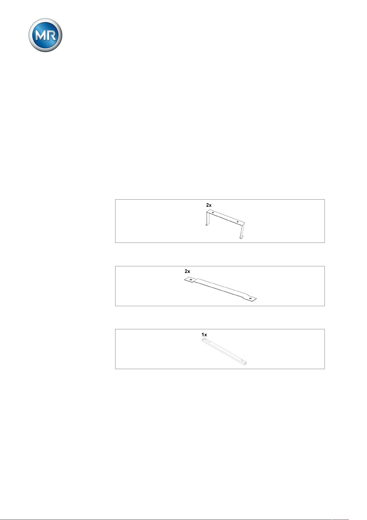
▪ Control panel bracket pre-mounted on device's housing
Figure1: Control panel bracket
▪ Mounting bracket for wall mounting
Figure2: Mounting bracket
▪ Covering strip for door
Figure3: Covering strip
Optional:
▪ Cap rail clip
Maschinenfabrik Reinhausen GmbH 201914 2117246/05 ENTAPCON®230 basic
Page 15

4 Product description
Figure4: Cap rail clip
Please note the following:
▪ Check the shipment for completeness on the basis of the shipping docu-
ments.
▪ Store the parts in a dry place until installation.
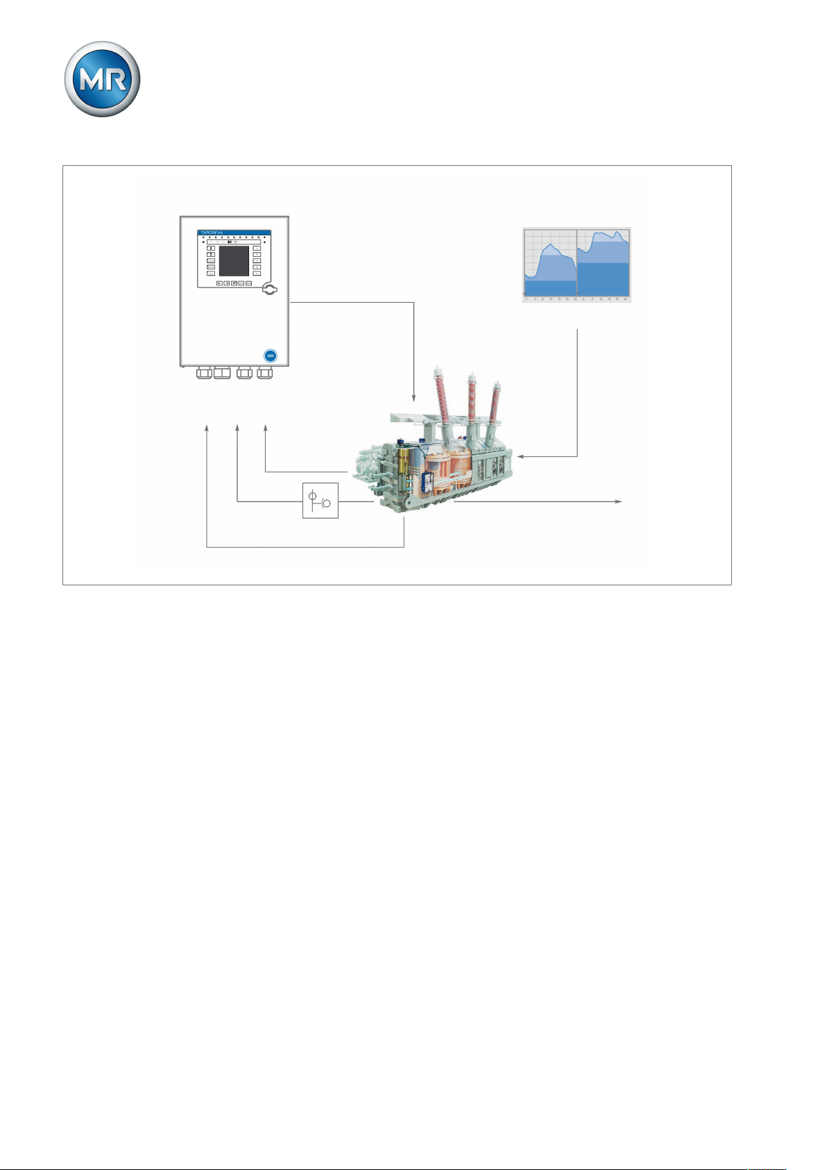
4.2 Function description of the voltage regulation
The TAPCON® serves to keep constant the output voltage of a transformer
with an on-load tap-changer.
The TAPCON® compares the transformer's measured voltage (U
defined reference voltage (U
). The difference between U
desired
actual
) with a
actual
and U
desired
is the control deviation (dU).
The TAPCON® parameters can be optimally adjusted to the line voltage response to achieve a balanced control response with a small number of tapchange operations.
The following diagram shows an overview of voltage regulation.
Maschinenfabrik Reinhausen GmbH 2019 152117246/05 EN TAPCON®230 basic
Page 16
4 Product description
Regulation section
regulating transformer
Summer Winter
Load profile of grid
Control variable for
line voltage
Automatic voltage regulator
TAPCON® 230 basic
Measurement
transformer
Line voltage
Desired value
Inputs,
digital and analog
I
V
Figure5: Overview of voltage regulation
4.3 Performance features
The TAPCON® is responsible for controlling tapped transformers.
Apart from control tasks, the TAPCON® provides additional functions such
as:
▪ Integrated monitoring functions:
– Undervoltage blocking and overvoltage blocking
– Overvoltage detection with high-speed return
▪ Compensation for voltage drops on the line (line drop compensation)
▪ Compensation for voltage fluctuations in the meshed grid (Z compensa-
tion)
▪ Digital inputs and outputs can be individually programmed on-site by the
customer
▪ Additional indicators using LEDs outside the display for freely selectable
functions
▪ Display of all measured values such as voltage, current, active power, ap-
parent power or reactive power, power factor (cosφ)
▪ Selection of 3 different desired values
Maschinenfabrik Reinhausen GmbH 201916 2117246/05 ENTAPCON®230 basic
Page 17

4 Product description
4.4 Operating modes
The device can be operated in the following operating modes:
Auto mode (AUTO)
In auto mode, the voltage is automatically controlled in accordance with the
set parameters. You cannot change further device settings in auto mode.
There is no active management by a higher level control system in this operating mode.
Manual mode (MANUAL)
In manual mode, there is no automatic control. The motor-drive unit can be
controlled via the device's operating panel. You can change the device settings.
Local mode (LOCAL)
There is no active management by a superordinate control system in this operating mode.
Remote mode (REMOTE)
In remote mode, you can perform commands using an external control level.
In this case, manual operation of the , , and keys is dis-
abled.
+ LOCAL + REMOTE + LOCAL + REMOTE
Automatic regulation Yes Yes No No
Tap-change operation using operating
controls
Tap-change operation using inputs No No No Yes
Table4: Overview of operating modes
No No Yes No
4.5 Hardware
Maschinenfabrik Reinhausen GmbH 2019 172117246/05 EN TAPCON®230 basic
Page 18
4 Product description
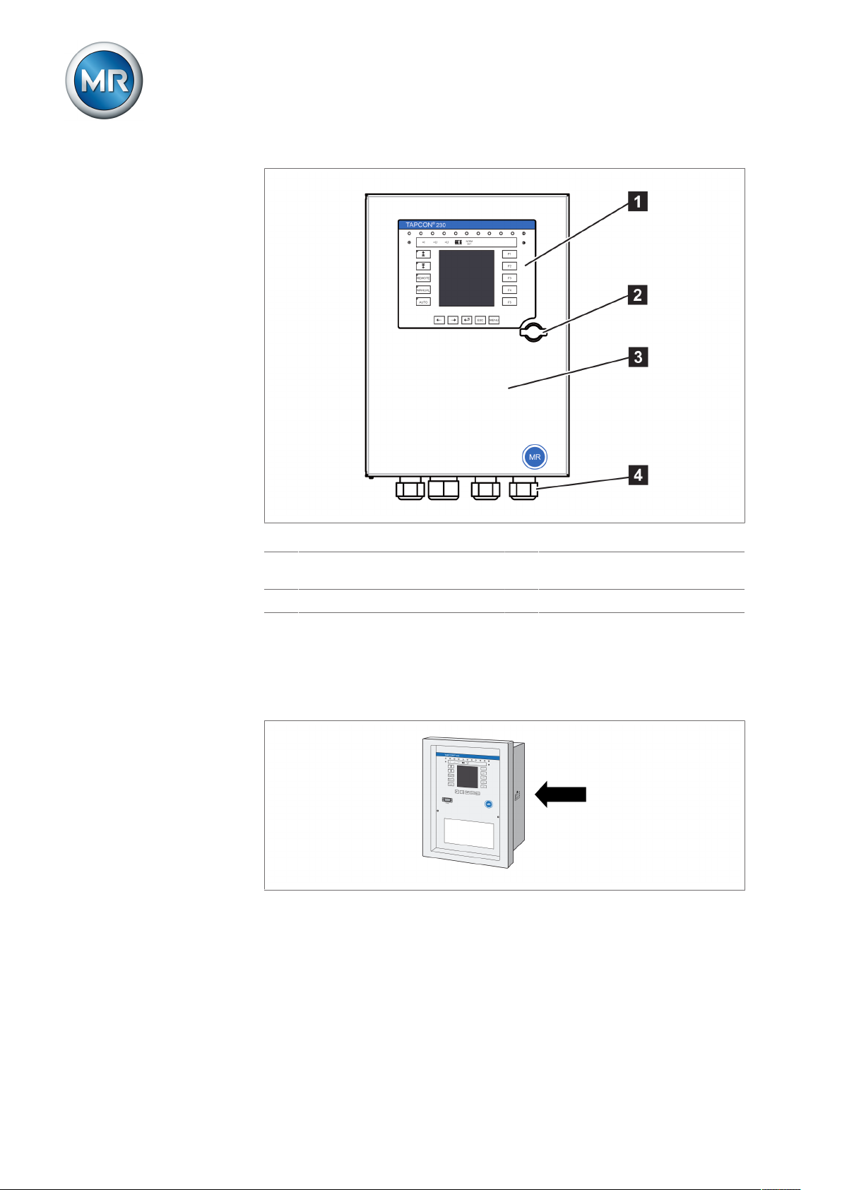
Figure6: Hardware
1 Operating panel with display and
LEDs
2 Door lock 4 Metric cable glands
4.5.1 Name plate
The name plate is on the outside of the device:
Figure7: Name plate
3 Door
Maschinenfabrik Reinhausen GmbH 201918 2117246/05 ENTAPCON®230 basic
Page 19
4 Product description
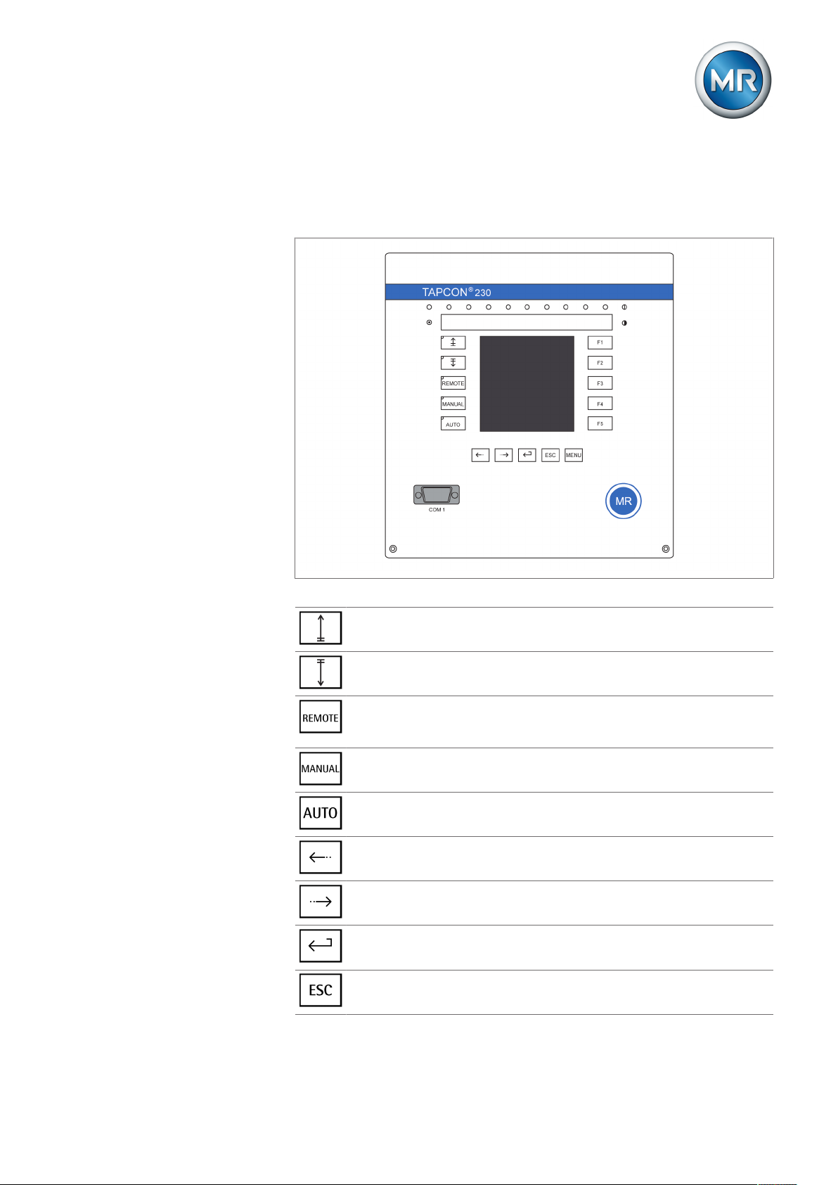
4.5.2 Operating controls
The device has 15 pushbuttons. The illustration below is an overview of all
the device's operating controls.
Figure8: Operating controls
RAISE key: Sends control command for raise tap-change to the motordrive unit in manual mode.
LOWER key: Sends control command for lower tap-change to the motordrive unit in manual mode.
REMOTE key: Activate/deactivate "Remote" operating mode. When you
deactivate this operating mode, the "Local" operating mode is automatically activated.
MANUAL key: Activate "Manual mode" operating mode.
AUTO key: Activate "Auto mode" operating mode.
PREV key: Change measured value display and switch to previous parameters.
NEXT key: Change measured value display and switch to next parameters.
ENTER key: Confirm selection and save modified parameters.
ESC key: Escape current menu and select previous menu levels.
Maschinenfabrik Reinhausen GmbH 2019 192117246/05 EN TAPCON®230 basic
Page 20
MENU key: Select main menu.
F1 to F5 function keys: Select functions displayed on the screen.
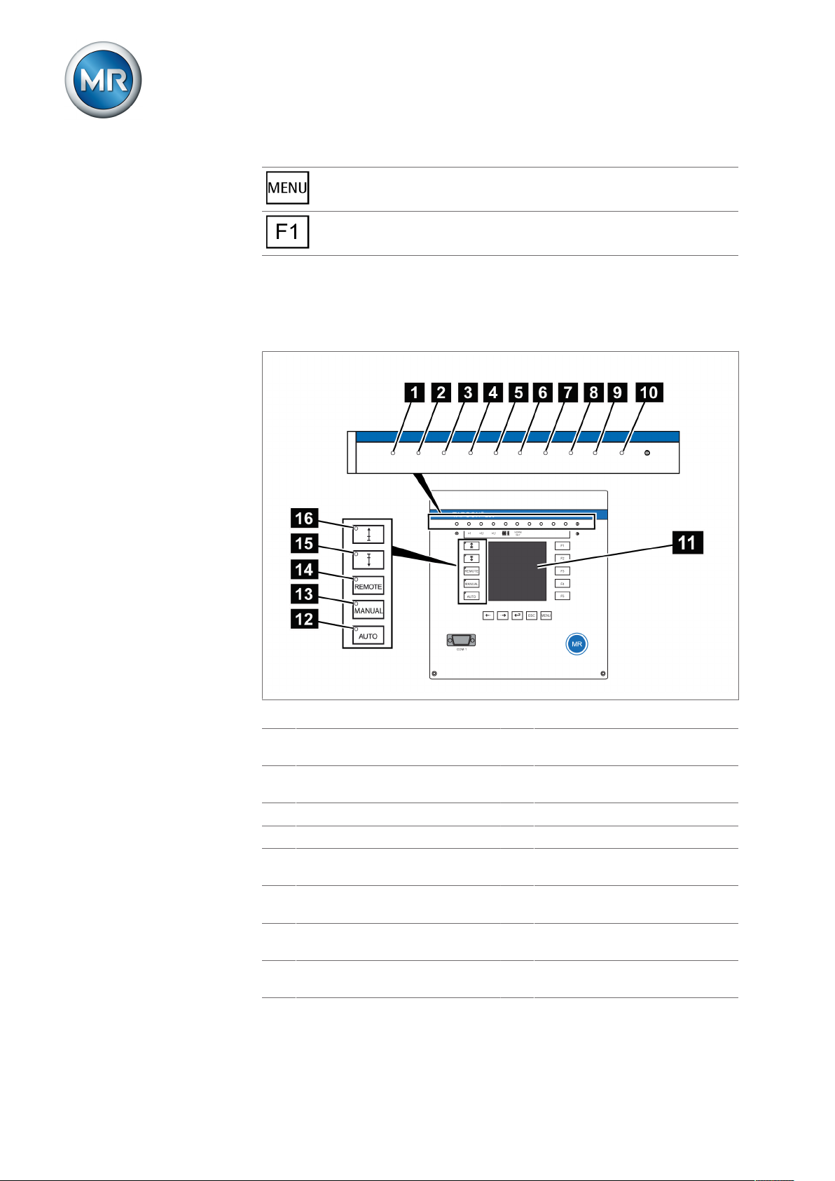
4.5.3 Display elements
The device has a graphics display and 15 LEDs , which indicate the various
operating statuses or events.
4 Product description
Figure9: Indicator elements
1 Operating status LED, green 9 LED 3, function can be freely as-
signed, yellow/green
2 Overcurrent blocking LED, red 10 LED 4, function can be freely as-
signed, yellow/red
3 Undervoltage blocking LED, red 11 Graphics display
4 Overvoltage blocking LED, red 12 Auto operating mode active LED
5 Parallel operation active LED,
green
6 NORMset active LED , green 14 Remote operating mode active
7 LED 1, function can be freely as-
signed, yellow
8 LED 2, function can be freely as-
signed, yellow
13 Manual operating mode active
LED
LED
15 Lower tap-change active LED
16 Raise tap-change active LED
Maschinenfabrik Reinhausen GmbH 201920 2117246/05 ENTAPCON®230 basic
Page 21
4 Product description
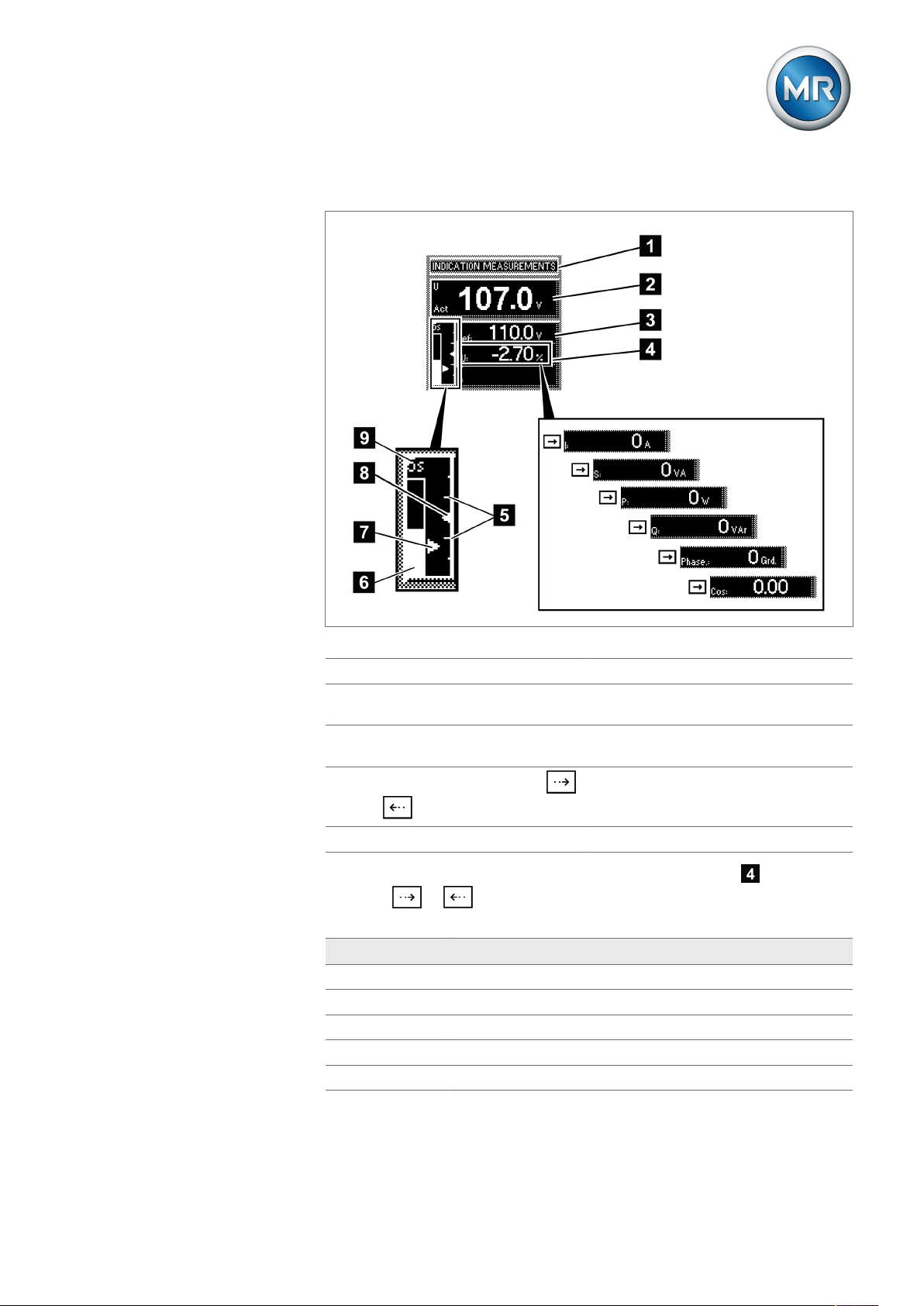
Display
Other measured values
Figure10: Display
1 Status line 6 Time bar for delay time T1
2 Measured voltage U
3 Reference voltage U
4
Other measured values (use
Act
Ref
7 Highlighting for measured voltage
U
Act
8 Highlighting for reference voltage
U
Ref
9 Remaining delay time T1
or to switch between them)
5 Bandwidth (upper and lower limit)
In auto mode and manual mode the measured value display can be set
using the or keys. The following measured values can be dis-
played:
Unit Measured value
∆U Control deviation
I Current
S Apparent power
P Active power
Q Reactive power
Maschinenfabrik Reinhausen GmbH 2019 212117246/05 EN TAPCON®230 basic
Page 22
Unit Measured value
Phase Phase angle
Cos Cosine
Table5: Measured value display
4 Product description
Status line
Current messages and events are displayed in the status line . You can
find more information about messages and events in the Messages chapter.
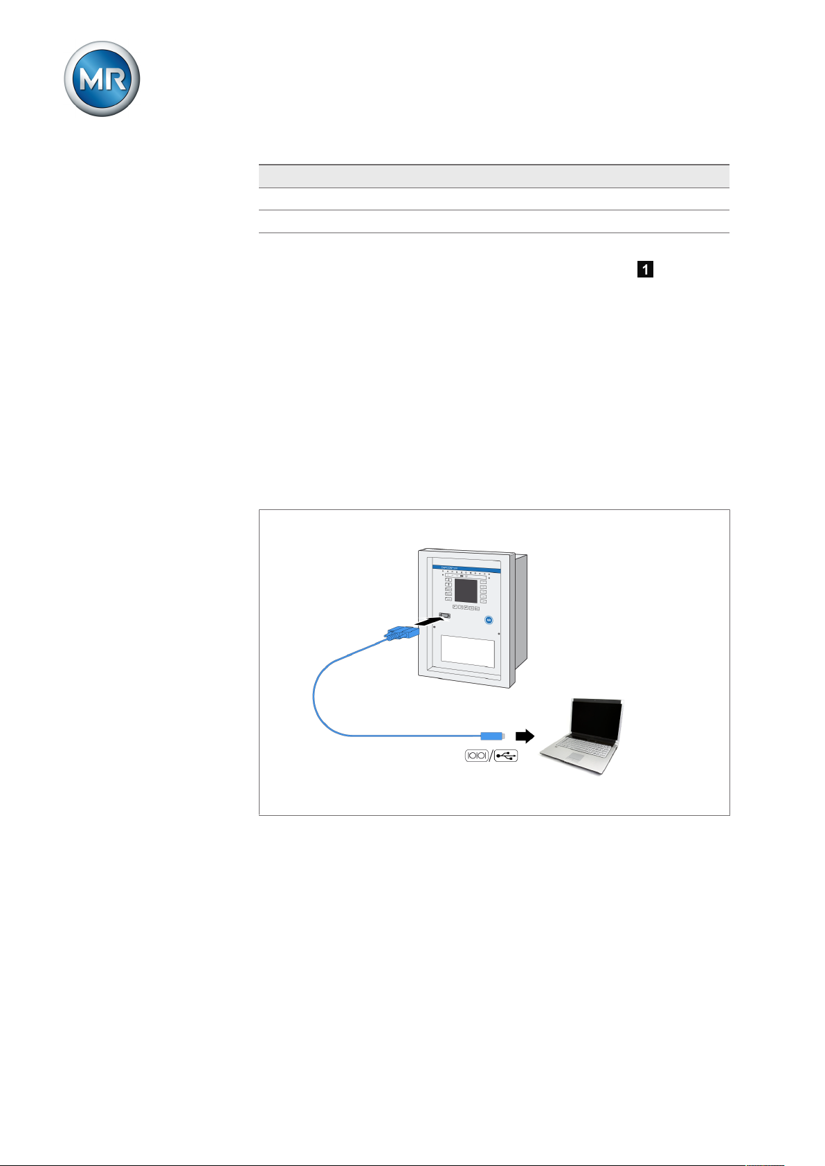
4.5.4 Serial interface
The parameters for the device can be set using a PC. The COM1 (RS232)
serial interface on the front panel is provided for this purpose. You can use
the connection cable supplied to establish a connection to your PC via the
RS232 or USB port (using the optional USB adapter).
TAPCON®-trol software is needed for parameterization via the serial interface. The software and the associated user guide can be downloaded from
www.reinhausen.com.
Figure11: Device connection to a PC
Maschinenfabrik Reinhausen GmbH 201922 2117246/05 ENTAPCON®230 basic
Page 23
4 Product description
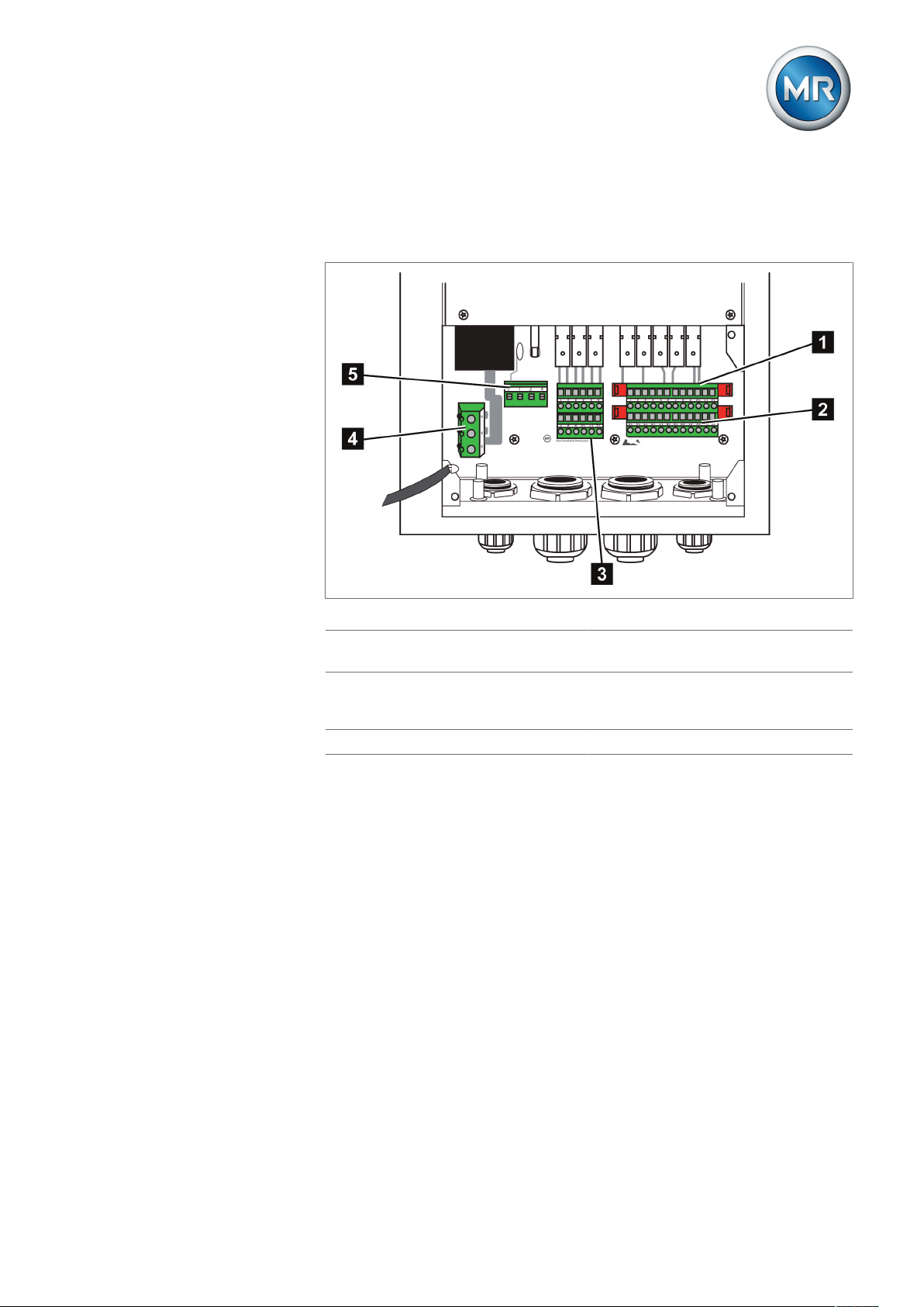
4.5.5 MIO card module
The device has an internal module. Carry out wiring in accordance with the
supplied connection diagram.
Figure12: MIO card
1 Relay outputs (terminal X4) 4 Current transformer connection
(terminal X1)
2 Signal inputs (terminal X4) 5 Voltage transformer connection
and network connection (terminal
X2)
3 Relay outputs (terminal X3)
Maschinenfabrik Reinhausen GmbH 2019 232117246/05 EN TAPCON®230 basic
Page 24

5 Packaging, transport and storage
5 Packaging, transport and storage
5.1 Packaging
5.1.1 Purpose
The packaging is designed to protect the packaged goods during transport,
loading and unloading as well as periods of storage in such a way that no
(detrimental) changes occur. The packaging must protect the goods against
permitted transport stresses such as vibration, knocks and moisture (rain,
snow, condensation).
The packaging also prevents the packaged goods from moving impermissibly within the packaging. The packaged goods must be prepared for shipment before actually being packed so that the goods can be transported
safely, economically and in accordance with regulations.
5.1.2 Suitability, structure and production
The goods are packaged in a sturdy cardboard box. This ensures that the
shipment is secure when in the intended transportation position and that
none of its parts touch the loading surface of the means of transport or touch
the ground after unloading.
The box is designed for a maximum load of 10kg.
Inlays inside the box stabilize the goods, preventing impermissible changes
of position, and protect them from vibration.
5.1.3 Markings
The packaging bears a signature with instructions for safe transport and correct storage. The following symbols apply to the shipment of non-hazardous
goods. Adherence to these symbols is mandatory.
Protect against
moisture
Table6: Shipping pictograms
Top Fragile Attach lifting
gear here
Center of mass
5.2 Transportation, receipt and handling of shipments
In addition to oscillation stress, jolts must also be expected during transportation. In order to prevent possible damage, avoid dropping, tipping,
knocking over and colliding with the product.
Maschinenfabrik Reinhausen GmbH 201924 2117246/05 ENTAPCON®230 basic
Page 25

5 Packaging, transport and storage
If a crate tips over, falls from a certain height (e.g. when slings tear) or is
subject to an unbroken fall, damage must be expected regardless of the
weight.
Every delivered shipment must be checked for the following by the recipient
before acceptance (acknowledgment of receipt):
▪ Completeness based on the delivery slip
▪ External damage of any type
The checks must take place after unloading when the crate or transport container can be accessed from all sides.
Visible damage If external transport damage is detected on receipt of the shipment, proceed
as follows:
▪ Immediately record the transport damage found in the shipping docu-
ments and have this countersigned by the carrier.
▪ In the event of severe damage, total loss or high damage costs, immedi-
ately notify the sales department at Maschinenfabrik Reinhausen and the
relevant insurance company.
▪ After identifying damage, do not modify the condition of the shipment fur-
ther and retain the packaging material until an inspection decision has
been made by the transport company or the insurance company.
▪ Record the details of the damage immediately onsite together with the
carrier involved. This is essential for any claim for damages!
▪ If possible, photograph damage to packaging and packaged goods. This
also applies to signs of corrosion on the packaged goods due to moisture
inside the packaging (rain, snow, condensation).
▪ Be absolutely sure to also check the sealed packaging.
Hidden damage When damages are not determined until unpacking after receipt of the ship-
ment (hidden damage), proceed as follows:
▪ Make the party responsible for the damage liable as soon as possible by
telephone and in writing, and prepare a damage report.
▪ Observe the time periods applicable to such actions in the respective
country. Inquire about these in good time.
With hidden damage, it is very hard to make the transportation company (or
other responsible party) liable. Any insurance claims for such damages can
only be successful if relevant provisions are expressly included in the insurance terms and conditions.
Maschinenfabrik Reinhausen GmbH 2019 252117246/05 EN TAPCON®230 basic
Page 26

5 Packaging, transport and storage
5.3 Storage of shipments
When selecting and setting up the storage location, ensure the following:
▪ Protect stored goods against moisture (flooding, water from melting snow
and ice), dirt, pests such as rats, mice, termites and so on, and against
unauthorized access.
▪ Store the crates on timber beams and planks as a protection against ris-
ing damp and for better ventilation.
▪ Ensure sufficient carrying capacity of the ground.
▪ Keep entrance paths free.
▪ Check stored goods at regular intervals. Also take appropriate action after
storms, heavy rain or snow and so on.
Maschinenfabrik Reinhausen GmbH 201926 2117246/05 ENTAPCON®230 basic
Page 27
6 Mounting
6 Mounting
This chapter describes how to correctly install and connect the device. Observe the connection diagrams provided.
DANGER
WARNING
NOTICE
Electric shock!
Risk of fatal injury due to electrical voltage. Always observe the following
safety regulations when working in or on electrical equipment.
► Disconnect the equipment.
► Lock the equipment to prevent an unintentional restart.
► Make sure all poles are de-energized.
► Ground and short-circuit.
► Cover or cordon off adjacent energized parts.
Electric shock!
Dangerous high voltages may occur when a current transformer is operated
with an open secondary circuit. This can lead to death, injuries and property
damage.
► Never operate a current transformer with an open secondary circuit;
short-circuit the current transformer to prevent this.
► Observe the information in the current transformer operating instructions.
Damage to the device!
Electrostatic discharge may cause damage to the device.
► Take precautionary measures to prevent the build-up of electrostatic
charges on work surfaces and personnel.
6.1 Preparation
The following tools are needed for mounting:
▪ Provided 3mm Allen key (included in delivery)
▪ Small screwdriver for connecting the signal lines and supply lines
Other tools may be needed depending on installation location.
6.2 Mounting device
You can mount the device in the following installation versions:
▪ Flush panel mounting
▪ Wall mounting
Maschinenfabrik Reinhausen GmbH 2019 272117246/05 EN TAPCON®230 basic
Page 28
6 Mounting
▪ Wall mounting with mounting brackets
▪ Rail mounting (optional)
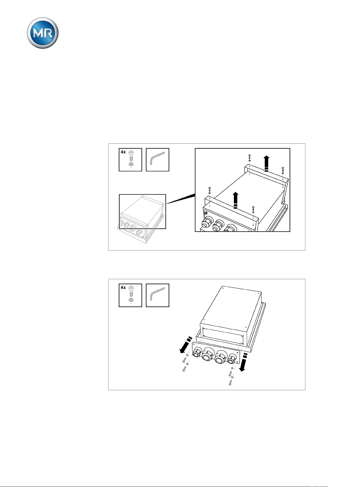
Preparing for mounting
Before commencing mounting, the two mounting brackets back on the rear
of the device must be removed and the cable gland plate taken off. To do so,
proceed as follows:
1. Loosen the 4 Allen screws with attached Allen key to remove the mount-
ing brackets.
Figure13: Loosen mounting bracket
2. Loosen the 4 Allen screws with attached Allen key to remove the cable
gland plate.
Figure14: Loosen cable gland plate
ð The mounting brackets and the cable gland plate are removed.
The relevant installation versions are described in the following sections.
Maschinenfabrik Reinhausen GmbH 201928 2117246/05 ENTAPCON®230 basic
Page 29
6 Mounting
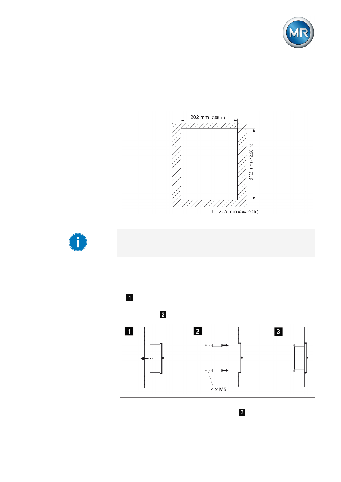
6.2.1 Flush panel mounting
For flush panel mounting , the device is inserted through a cutout in the control panel and fixed to the control panel or control cabinet from behind using
the mounting brackets. The diagram below shows the dimensions required
for the control panel cutout.
Figure15: Dimensions for the cutout
A wall thickness of 2...5 mm (0.08...0.2in) is needed for secure device fixing.
To mount the device in the control panel or control cabinet, proceed as follows:
1. Close the device's door.
2. Insert the device through the cutout in the control panel or control cabinet
.
3. Screw both fixing brackets to the rear of the device with 2 hexagon socket
screws each .
Figure16: Flush panel mounting
ð The device is mounted and can be wired up .
Maschinenfabrik Reinhausen GmbH 2019 292117246/05 EN TAPCON®230 basic
Page 30
Proceed with wiring as shown in the connection diagram and as described in
the Connecting device [►Section 6.3, Page 34] section.
6.2.2 Wall mounting with mounting brackets
As an alternative to mounting the device directly on the wall, it can be fixed
to the wall using the mounting brackets supplied.
Drill 4 holes, each 5.5 mm (0.22in) in diameter, in the wall as shown in the
drilling template below.
6 Mounting
Figure17: Bores for wall mounting with mounting brackets
To mount the device using the mounting brackets, proceed as follows:
1. Lay the device carefully on the door.
2. Screw the mounting brackets supplied to the back of the device using the
hexagon socket screws .
3. Fix the device on the wall using 4 screws (maximum diameter of 5
mm/0.22in) .
The screws for fixing to the wall are not included in the scope of supply. The
screw length required depends on the wall thickness.
Figure18: Wall mounting with mounting brackets
ð The device is mounted and can be wired up .
Maschinenfabrik Reinhausen GmbH 201930 2117246/05 ENTAPCON®230 basic
Page 31

6 Mounting
Proceed with wiring as shown in the connection diagram and as described in
the Connecting device [►Section 6.3, Page 34] section.
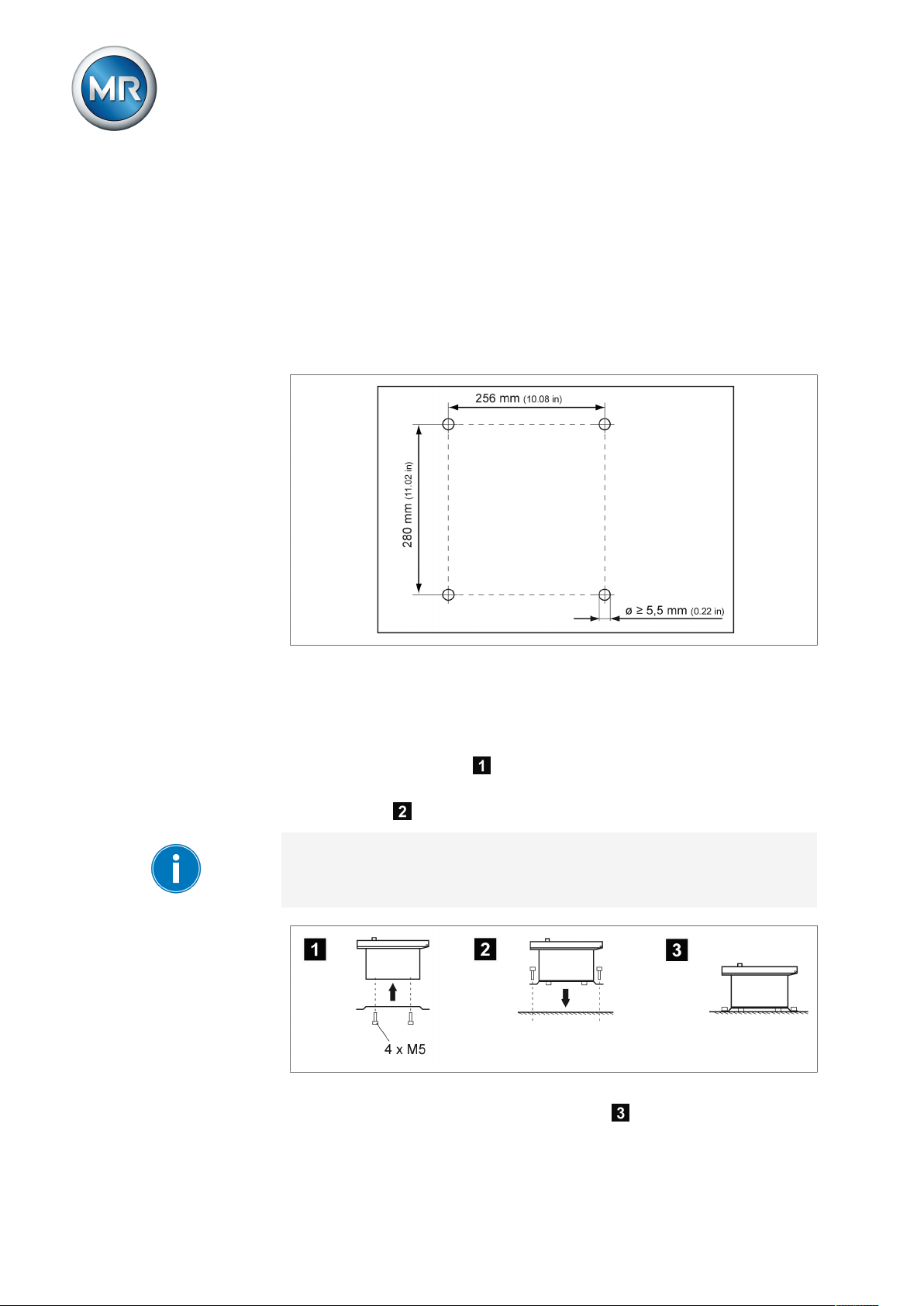
6.2.3 Cap rail mounting
As an option, the device can be fitted with a cap rail clip (aluminum extrusion
with wire spring integrated at center). This enables you to mount the device
on a cap rail.
When attaching the cap rail, sufficient space for the device must be planned
for. At least 5cm (1.97in) of space must be provided above and at least
35cm (13.78in) below the fixing screws of the cap rail for the device housing.
To mount the device using the cap rail, proceed as follows:
1. Lay the device carefully on the door.
2. Screw the cap rail clip into the two top holes on the rear with the M5
hexagon socket countersunk head screws provided .
3. Suspend the cap rail clip in the cap rail and push the underside carefully
towards the wall until the clip can be heard to click into place .
Figure19: Cap rail mounting
ð The device is mounted and can be wired up .
Proceed with wiring as shown in the connection diagram and as described in
the Connecting device [►Section 6.3, Page 34] section.
Maschinenfabrik Reinhausen GmbH 2019 312117246/05 EN TAPCON®230 basic
Page 32
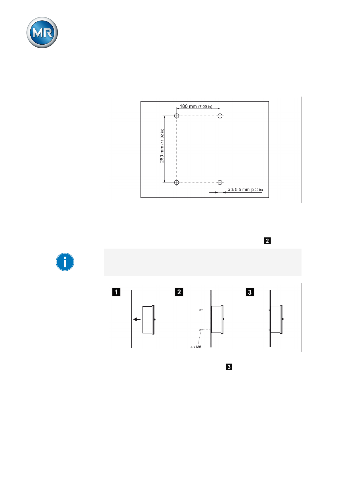
6.2.4 Wall mounting
For wall mounting, , the device is fixed directly to the wall. Drill 4 holes, each
5.5mm in diameter, in the wall as shown in the drilling template below.
6 Mounting
Figure20: Drilling template for wall mounting
To mount the device directly on the wall, proceed as follows:
ü Close the device's door.
► Fix the device on the wall from behind using 4 screws (M5) .
The screws for wall mounting are not included in the scope of supply. The
screw length required depends on the wall thickness.
Figure21: Wall mounting
ð The device is mounted and can be wired up .
Proceed with wiring as shown in the connection diagram and as described in
the Connecting device section.
Maschinenfabrik Reinhausen GmbH 201932 2117246/05 ENTAPCON®230 basic
Page 33

6 Mounting
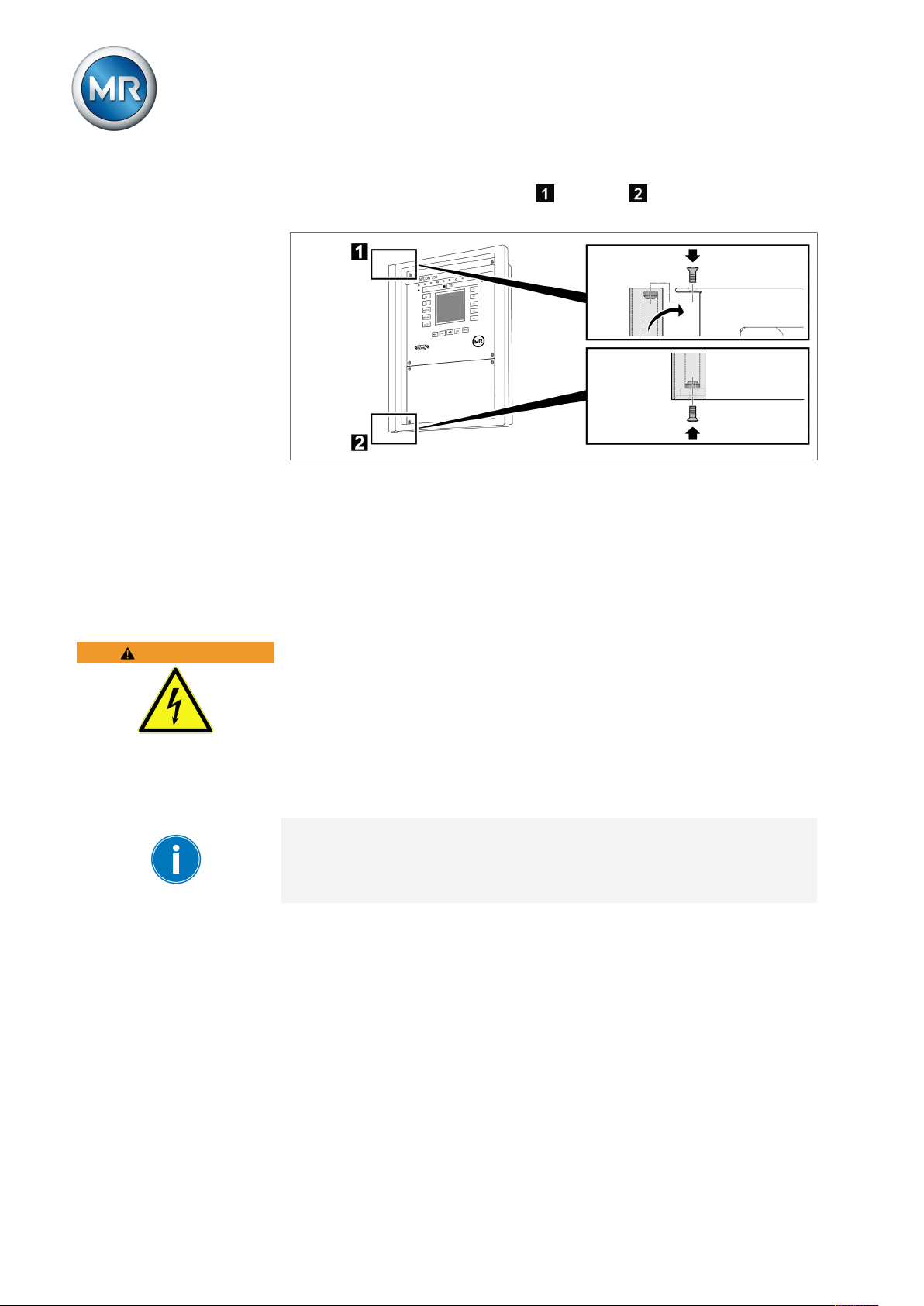
6.2.5 Removing the door
When the door is fitted, the device satisfies protection category IP54. The
door may be removed if the device is used solely in a dry atmosphere protected from environmental influences. The device then satisfies protection
category IP21.
Proceed as follows to remove the door:
1. Loosen the grounding strap on the door using an open-end wrench.
Figure22: Remove door
2. Unscrew the fixing bolt using a slotted screwdriver and lift the door out
of the upper mounting .
Figure23: Lift door from the suspension mount
Maschinenfabrik Reinhausen GmbH 2019 332117246/05 EN TAPCON®230 basic
Page 34
6 Mounting
3. Hook the cover strip in the upper and lower suspension mount and
fasten it with the provided raised countersunk head screws.
Figure24: Fasten covering strip
ð The door is removed and the exposed attachment points for the door are
covered.
WARNING
6.3 Connecting device
The following section describes how to establish the electrical connection to
the device.
Electric shock!
Connection errors can lead to death, injury or property damage.
► Ground the device with a protective conductor using the grounding screw
on the housing.
► Note the phase difference of the secondary terminals for the current
transformer and voltage transformer.
► Connect the output relays correctly to the motor-drive unit.
Supply the voltage via separators and ensure that current paths can be
short circuited. Fit the separator, clearly labeled, close to the device's power
supply so that it is freely accessible. This ensures that the device can be replaced with ease in the event of a defect.
Wiring information
Note this procedure for the wiring:
ü To obtain a better overview when connecting cables, only use as many
leads as necessary.
ü Note the connection diagram.
ü Use only the specified cables for wiring. Note the cable recommendation
[►Section 6.3.1, Page 35].
ü Wire the leads to the system periphery [►Section 6.3.4, Page 39].
1. Strip insulation from leads and wires.
Maschinenfabrik Reinhausen GmbH 201934 2117246/05 ENTAPCON®230 basic
Page 35

6 Mounting
2. Crimp stranded wires with wire end sleeves.
6.3.1 Cable recommendation
Please note the following recommendation from Maschinenfabrik Reinhausen when wiring the device.
Excessive line capacitance can prevent the relay contacts from breaking the
contact current. In control circuits operated with alternating current, take into
account the effect of the line capacitance of long control cables on the function of the relay contacts.
Cable Terminal Cable type Wire cross-
section
Signal inputs X4 Shielded 1.5 mm² - 0.6 Nm
RS232 SUB-D - Shielded 0.25 mm² 25 m Relay outputs* X3 Unshielded 1.5 mm² - 0.6 Nm
Relay outputs* op-
tional
Current measure-
ment
Voltage measure-
ment
Power supply X2:3/4 Unshielded 1.5 mm² - 0.6 Nm
Table7: Cable recommendation for connection cable
X4 Unshielded 1.5 mm² - 0.6 Nm
X1:5/6/9 Unshielded 4 mm² - 1.5 Nm
X2:1/2 Shielded 1.5 mm² - 0.6 Nm
Max. length Max. permissible
torque
*) Observe line capacitance, see note above.
Cable clips X1 to X4 are on the MIO card of the device.
6.3.2 Information about laying fiber-optic cable
To ensure the smooth transfer of data via the fiber-optic cable, you must ensure that mechanical loads are avoided when laying the fiber-optic cable and
later on during operation. Also observe the information from the manufacturer of the fiber-optic cable and the following instructions:
▪ Radii must not fall below the minimum permissible bend radii (do not bend
fiber-optic cable).
▪ The fiber-optic cables must not be over-stretched or crushed. Observe the
permissible load values.
▪ The fiber-optic cables must not be twisted.
Maschinenfabrik Reinhausen GmbH 2019 352117246/05 EN TAPCON®230 basic
Page 36

▪ Be aware of sharp edges because they can damage the fiber-optic cable's
coating during laying or can place mechanical loads on the coating later
on.
▪ Provide a sufficient cable reserve near distributor cabinets. Lay the re-
serve such that the fiber-optic cable is neither bent nor twisted when tightened.
6.3.3 Electromagnetic compatibility
The device has been developed in accordance with applicable EMC standards. The following points must be noted in order to maintain the EMC
standards.
6.3.3.1 Wiring requirement of installation site
Note the following when selecting the installation site:
▪ The system's overvoltage protection must be effective.
▪ The system's ground connection must comply with all technical regula-
tions.
▪ Separate system parts must be joined by a potential equalization.
▪ The device and its wiring must be at least 10m away from circuit-break-
ers, load disconnectors and busbars.
6 Mounting
6.3.3.2 Wiring requirement of operating site
Note the following when wiring the operating site:
▪ Route the connecting leads in grounded metal cable ducts.
▪ Do not route lines which cause interference (e.g. power lines) and lines
susceptible to interference (e.g. signal lines) in the same cable duct.
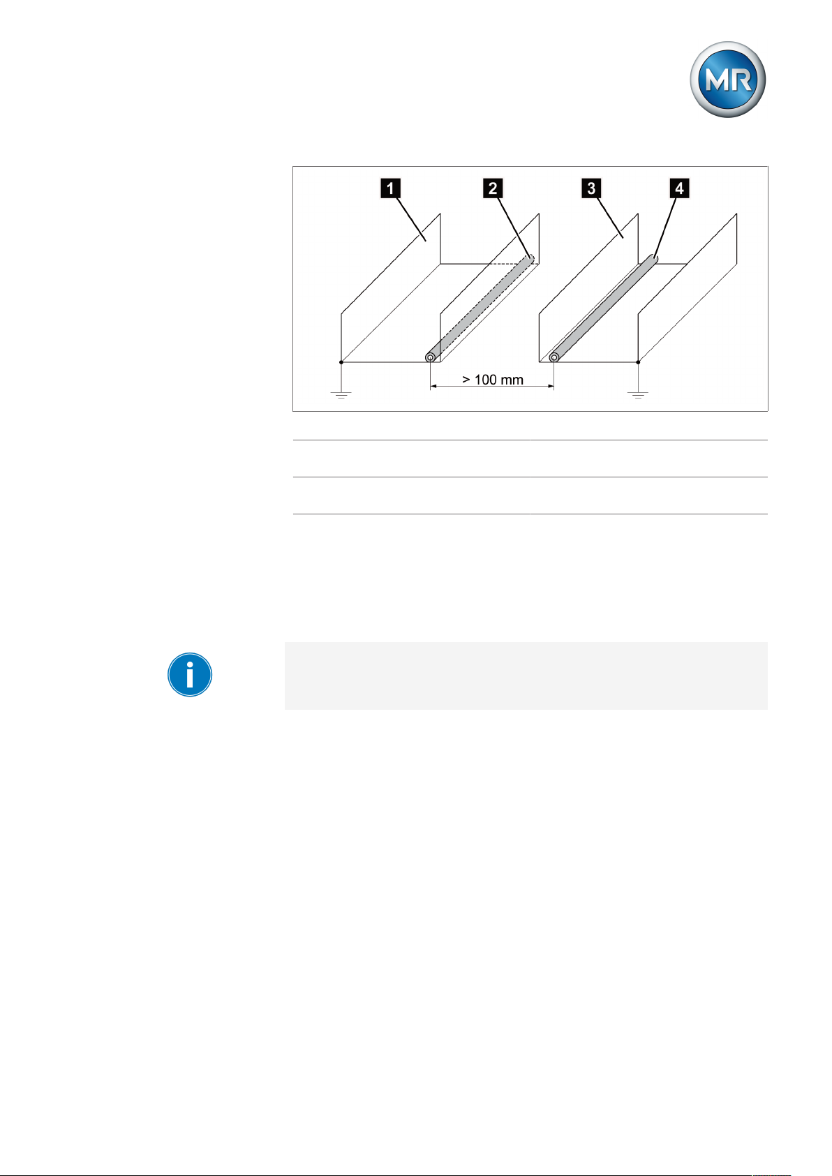
▪ Maintain a distance of more than 100 mm between lines which cause in-
terference and those which are susceptible to interference.
Maschinenfabrik Reinhausen GmbH 201936 2117246/05 ENTAPCON®230 basic
Page 37
6 Mounting
Figure25: Recommended wiring
1 Cable duct for lines causing inter-
ference
2 Line causing interference (e.g.
power line)
3 Cable duct for lines susceptible to
interference
4 Line susceptible to interference
(e.g. signal line)
▪ Short-circuit and ground reserve lines.
▪ Never connect the device with a multi-wire collective pipe.
▪ For signal transmission, use shielded lines with individual conductors (out-
going conductor / return conductor) twisted in pairs.
▪ Connect full surface of shielding (360º) to device or to a nearby grounding
bar.
Using single conductors may limit the effectiveness of the shielding. Connect close-fitting shielding to cover all areas.
Maschinenfabrik Reinhausen GmbH 2019 372117246/05 EN TAPCON®230 basic
Page 38

Figure26: Recommended connection of the shielding
6 Mounting
1 Connection of the shielding via a
single conductor
6.3.3.3 Wiring requirement in control cabinet
Note the following when wiring the control cabinet:
▪ The control cabinet where the device will be installed must be prepared in
accordance with EMC requirements:
– Functional division of control cabinet (physical separation)
– Constant potential equalization (all metal parts are joined)
– Line routing in accordance with EMC requirements (separation of lines
which cause interference and those susceptible to interference)
– Optimum shielding (metal housing)
– Overvoltage protection (lightning protection)
– Collective grounding (main grounding rail)
– Cable bushings in accordance with EMC requirements
– Any contactor coils present must be interconnected
▪ The device's connection cables must be laid in close contact with the
grounded metal housing or in metallic cable ducts with a ground connection.
▪ Signal lines and power lines/switching lines must be laid in separate cable
ducts.
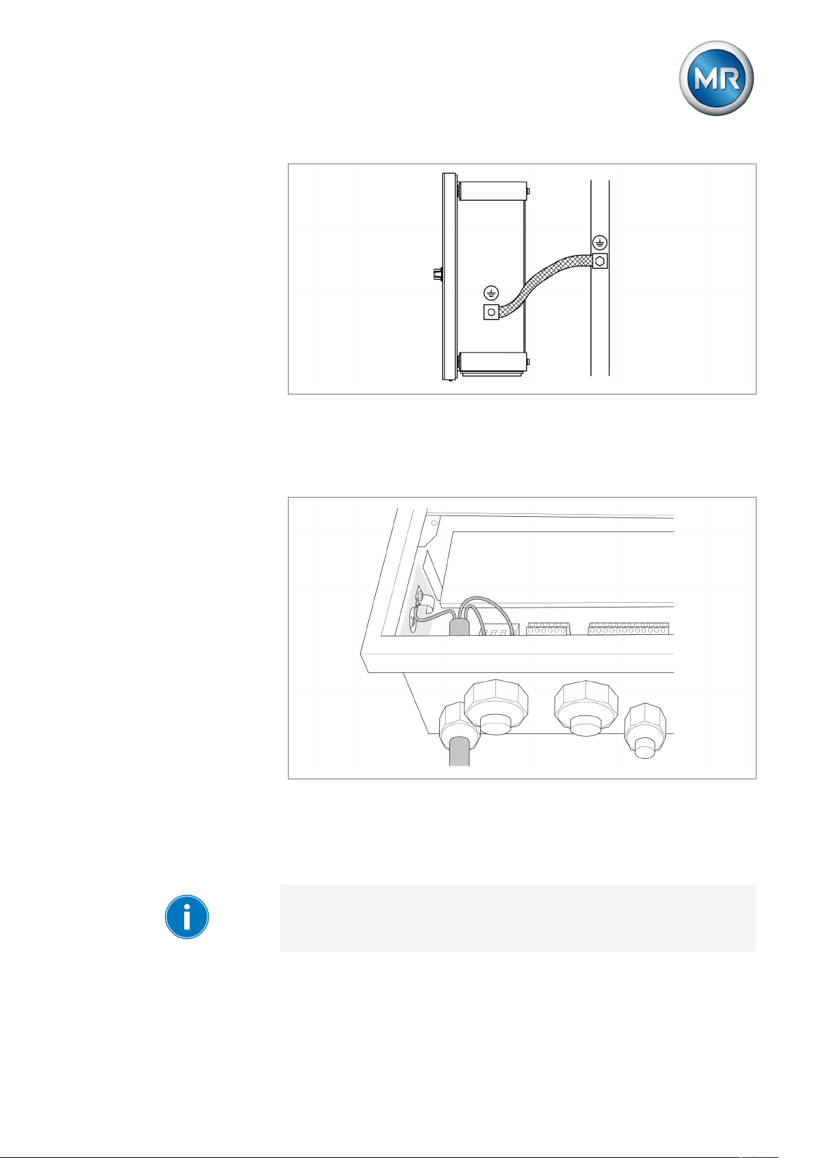
▪ The device must be grounded at the screw provided, the protective
grounding connection, using a ground strap (cross-section min. 8 mm²).
2 Full-surface connection of the
shielding
Maschinenfabrik Reinhausen GmbH 201938 2117246/05 ENTAPCON®230 basic
Page 39
6 Mounting
Figure27: Ground strap connection
Ground connection for wiring inside the device
The diagram below shows the ground connection for wiring inside the de-
vice.
Figure28: Grounding inside the device
6.3.4 Connecting cables to the system periphery
To obtain a better overview when connecting cables, only use as many
leads as necessary.
Maschinenfabrik Reinhausen GmbH 2019 392117246/05 EN TAPCON®230 basic
Page 40

To connect cables to the system periphery, proceed as follows:
ü Use only the specified cables for wiring. Note the cable recommendation.
► Connect the lines to be wired to the device to the system periphery as
shown in the connection diagrams supplied.
6.3.5 Supplying the voltage regulator using auxiliary voltage
The device is normally supplied by the voltage transformer. If the voltage
transformer does not provide the supply voltage and power (see "Technical
Data") needed for operation, the device must be supplied via a 88...265V
AC/DC, 50...60Hz auxiliary supply .
Proceed as follows to supply the device with auxiliary voltage:
1. NOTICE! Voltage transformer damage Connecting an auxiliary voltage
when bridges are present between the X2:1/3 and X2:2/4 terminals can
result in voltage transformer damage. Remove the bridges between the
terminals X2:1/3 and X2:2/4.
2. Connect the voltage transformer to terminals X2:1 and X2:2.
3. Connect the auxiliary voltage using the following terminals: X2:3 and X2:4.
6 Mounting
Figure29: Voltage transformer and auxiliary supply connections
6.3.6 Wiring device
To obtain a better overview when connecting cables, only use as many
leads as necessary.
To wire the device, proceed as follows:
ü Use only the specified cables for wiring. Note the cable recommendation
[►Section 6.3.1, Page 35].
ü Wire the lines to the system periphery [►Section 6.3.4, Page 39].
Maschinenfabrik Reinhausen GmbH 201940 2117246/05 ENTAPCON®230 basic
Page 41

6 Mounting
1. Remove 4 hexagon socket screws from cover plate and take off cover
plate.
2. Disconnect the connectors required.
3. Remove 4 hexagon socket screws from the cable gland plate and take off
the cable gland plate.
4. Remove dummy plug from required cable glands in order to guide cables
through.
Unnecessary cable glands must be sealed with dummy plugs to guarantee
the IP54 protection category.
5. Strip insulation from lines and leads.
6. Crimp stranded wires with core cable ends.
7. Guide cables through the cable gland
8. Guide leads into corresponding connector terminals.
9. Fasten screws for the corresponding terminals using a screwdriver.
10. Guide the cable gland plate into the device opening provided for this pur-
pose.
11. Plug connectors into the correct slots.
12. Secure cable gland plate to device housing with 4 hexagon socket
screws.
NOTICE
6.3.7 Checking functional reliability
To ensure that the device is wired correctly, check its functional reliability.
Damage to device and system periphery
An incorrectly connected device can lead to damages in the device and system periphery.
► Check the entire configuration before commissioning.
► Prior to commissioning, be sure to check the actual voltage and operating
voltage.
Check the following:
▪ Once you have connected the device to the grid, the screen displays the
MR logo and then the operating screen.
▪ The green Operating display LED top left on the device's front panel lights
up.
The device is fully mounted and can be configured. The actions required for
this are described in the following chapter.
Maschinenfabrik Reinhausen GmbH 2019 412117246/05 EN TAPCON®230 basic
Page 42

7 Commissioning
7 Commissioning
You need to set several parameters and perform function tests before commissioning the device. These are described in the following sections.
NOTICE
Damage to device and system periphery
An incorrectly connected device can lead to damages in the device and system periphery.
► Check the entire configuration before commissioning.
► Prior to commissioning, be sure to check the actual voltage and operating
voltage.
We recommend using a device for industrial instrumentation to record the
actual transformer voltage value in order to evaluate how the device is functioning.
7.1 Setting the display contrast
You can adjust the contrast in the display with the help of an adjustment
screw on the front of the device. To adjust the contrast, proceed as follows:
► Use a screwdriver to turn the adjustment screw on the front until the con-
trast is adjusted to the desired setting.
Figure30: Setting the display contrast
7.2 Setting parameters
To commission the device, you must set the following parameters. For more
detailed information about the parameters, refer to the respective sections.
Maschinenfabrik Reinhausen GmbH 201942 2117246/05 ENTAPCON®230 basic
Page 43
7 Commissioning
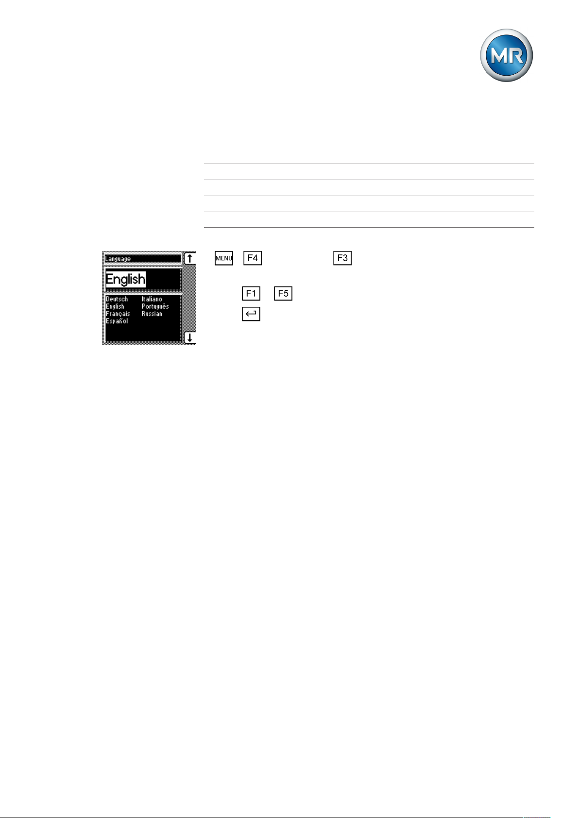
7.2.1 Setting the language
You can use this parameter to set the display language for the device. The
following languages are available:
English Italian
German Portuguese
French Russian
Spanish
To set the language, proceed as follows:
1. > Configuration > General.
ð Language
2. Press or to select the required language.
3. Press .
ð The language is set.
7.2.2 Setting further parameters
Set further parameters to commission the device. You will find more detailed
information about the respective parameters in the "Operation" [►Section 8,
Page 49] chapter.
Setting transformer data
Set the transformer data and phase difference of the current transformer and
voltage transformer:
1. Set primary transformer voltage [►Section 8.7.1, Page 82].
2. Set secondary transformer voltage [►Section 8.7.2, Page 82].
3. Set primary transformer current [►Section 8.7.3, Page 83].
4. Select current-transformer connection [►Section 8.7.4, Page 84].
5. Select transformer circuit [►Section 8.7.5, Page 84].
Setting NORMset
If you want to commission voltage regulation quickly, you can activate
NORMset mode. If you want to set the parameters yourself, continue with
the sections below.
► Activate NORMset and set the relevant parameters [►Section 8.3, Page
59].
Setting control parameters
Set the following control parameters:
1. Set desired value 1 [►Section 8.4.1, Page 63].
Maschinenfabrik Reinhausen GmbH 2019 432117246/05 EN TAPCON®230 basic
Page 44

7 Commissioning
2. Set the bandwidth [►Section 8.4.3.2, Page 66].
3. Set delay time T1 [►Section 8.4.4, Page 66].
Setting line drop compensation (optional)
If you need line drop compensation, you must set all important parameters
for this:
1. Select the LDC compensation method [►Section 8.6.1, Page 76].
2. Set the line data for the ohmic voltage drop Ur [►Section 8.6.1.1, Page
78].
3. Set the line data for the inductive voltage drop Ux [►Section 8.6.1.2,
Page 79].
7.3 Function tests
Before switching from manual mode to auto mode, Maschinenfabrik Reinhausen recommends carrying out function tests. These function tests are described in the following sections. Note the following points for all function
tests:
▪ You must ensure that REMOTE mode is disabled before you can control
the on-load tap-changer manually in manual mode.
▪ You can only activate the on-load tap-changer manually in manual mode
using the and keys.
▪ During the function test, you must set the most important parameters. De-
tails on the parameters listed can be found in the Operation [►Section 8,
Page 49] chapter.
7.3.1 Checking control functions
This section describes how you can check the device's control functions:
ü Supply voltage must be present.
1. Press to select manual mode.
2. Set transmission ratio for voltage transformer, current transformer and
measuring set-up.
3. Measure actual voltage and compare with the measured value displayed
on the device's main screen.
4. Press key several times to display the operating values for current,
power and phase angle and compare them with values of service instruments.
5. Control the on-load tap-changer manually with the or keys until
the measured voltage (U
the next stage.
6. Set desired value 1 to the value you want.
actual
) reaches the desired voltage (U
desired
) set in
Maschinenfabrik Reinhausen GmbH 201944 2117246/05 ENTAPCON®230 basic
Page 45

7 Commissioning
7. Set bandwidth depending on step voltage [►Section 8.4.3, Page 65].
8. Set delay time T1 to 20 seconds [►Section 8.4.4, Page 66].
9. Set control response T1 to linear [►Section 8.4.5, Page 67].
10. Press to raise the on-load tap-changer 1 step.
11. Press to select auto mode.
ð After 20 seconds, the device returns the on-load tap-changer to the
original operating position.
12. Press to select manual mode.
13. Press to lower the on-load tap-changer 1 step.
14. Press to select auto mode.
ð After 20 seconds, the device returns the on-load tap-changer to the
original operating position.
15. Press to select manual mode.
16. Set delay time T2 to 10 seconds [►Section , Page 68].
17. Activate delay time T2.
18. Press twice to raise the on-load tap-changer 2 steps.
19. Press to select auto mode.
ð After 20seconds, the device lowers the on-load tap-changer one step
and after another 10seconds another step.
20. Press to select manual mode.
21. Set delay time T1 [►Section 8.4.4, Page 66] and delay time T2 [►Section , Page 68] to the desired value.
We recommend a temporary setting of 100 seconds for delay time T1 when
commissioning the transformer. Depending on the operating conditions, you
can also specify the delay time following a longer observation period. In this
regard, it is useful to register how the actual voltage progresses and the
number of tap-change operations per day.
7.3.2 Checking additional functions
This section describes how you can check the following additional functions:
▪ Undervoltage blocking
▪ Overvoltage blocking
▪ Activation of desired values 2 and 3
▪ Line drop compensation
▪ Z compensation
Proceed as follows:
Maschinenfabrik Reinhausen GmbH 2019 452117246/05 EN TAPCON®230 basic
Page 46

7 Commissioning
Checking undervoltage blocking U<
1. Press to select manual mode.
2. Set undervoltage U < [%] to 85%.
3. Set the U< blocking parameter to On [►Section , Page 71].
4. Set desired value1 such that the measured voltage Uactual is below the
undervoltage U< [%] limit value.
Measured voltage = 100V
Desired value1 = Set to 120V (greater than 100V/0.85 = 117V).
ð The Undervoltage U< LED will light up.
ð After around 10seconds the Undervoltage message appears in the dis-
play and the relevant signaling relay is activated. Contact X4:1/3 closes
and contact X4:2/3 opens.
5. Press to select auto mode.
ð The device blocks and does not issue any control commands.
6. Press to select manual mode.
7. Reset the operating values for desired value1 and undervoltage U< [%]
to the desired operating values.
ð The function test for undervoltage blocking is complete.
Checking overvoltage blocking U>
1. Press to select manual mode.
2. Set overvoltage U> [%] to 115%.
3. Set the absolute limit values parameter to Off.
4. Set desired value1 such that the measured voltage Uactual is above the
overvoltage U> [%] limit value.
Measured voltage = 100V
Desired value1 = Set to 85V (less than 100V/1.15 = 87V).
ð The Overvoltage U> LED will light up.
ð The Overvoltage message appears in the display and the relevant sig-
naling relay is activated. Contact X4:1/3 closes and contact X4:2/3
opens.
5. Press to select auto mode.
ð The LOWER output relay emits a control command every 1.5seconds.
6. Press to select manual mode.
7. Reset the operating values for desired value1 and overvoltage U> [%]
to the desired operating values.
ð The function test for overvoltage blocking is complete.
Maschinenfabrik Reinhausen GmbH 201946 2117246/05 ENTAPCON®230 basic
Page 47

7 Commissioning
Checking desired value2 and desired value3
1. Press to select manual mode.
2. Set desired value2 to the value you want.
3. Apply voltage L+ to terminal X4:17 desired value2 (see connection diagram).
4. Press until the main screen is displayed.
ð Desired value2 is shown on the main screen.
5. Set desired value3 to the value you want.
6. Apply voltage L+ to terminal desired value3 (see connection diagram).
7. Press until the main screen is displayed.
ð Desired value3 is shown on the main screen.
ð The function test for desired value2 and desired value3 is complete.
Checking line drop compensation
If you want to use line drop compensation, you need to run this function test.
A load current of ≥10% of the nominal transformer current is needed for the
following function tests. Before the function test, ensure that all parameters
for line drop compensation and for Z compensation are set to 0.
1. Press to select manual mode.
2. Set the compensation method parameter to LDC.
3. Press until the main screen is displayed.
4. If necessary, press until the control deviation dU is shown.
ð The measured voltage must be within the bandwidth.
5. Set line drop compensation Ur parameter to 20.0V.
6. Press until the main screen is displayed.
7. If necessary, press until the control deviation dU is shown.
ð The value for control deviation dU must be negative.
8. Set line drop compensation Ur parameter to -20.0V.
9. Press until the main screen is displayed.
10. If necessary, press until the control deviation dU is shown.
ð The value for control deviation dU must be positive.
If the control deviation appears in the opposite direction, change the polarity
of the current transformer.
Maschinenfabrik Reinhausen GmbH 2019 472117246/05 EN TAPCON®230 basic
Page 48
7 Commissioning
11. Set the line drop compensation Ur and line drop compensation Ux
parameters to the desired operating values.
ð The function test for line drop compensation is complete.
Checking Z compensation
If you want to use Z compensation, you need to run this function test. A load
current of ≥10% of the nominal transformer current is needed for the following function test .
1. Press to select manual mode.
2. Set all parameters for line drop compensation and Z compensation to 0.
3. Set the compensation method parameter to Z.
4. Press until the main screen is displayed.
5. If necessary, press until the control deviation dU is shown.
ð The measured voltage must be within the bandwidth.
6. Set the Z compensation parameter to 15.0V.
7. Press until the main screen is displayed.
8. If necessary, press until the control deviation dU is shown.
ð The control deviation dU must be negative.
If the control deviation appears in the opposite direction, change the polarity
of the current transformer.
9. Set the Z compensation and Z compensation limit value parameters to
the desired operating values.
ð The function test for Z compensation is complete.
Maschinenfabrik Reinhausen GmbH 201948 2117246/05 ENTAPCON®230 basic
Page 49

8 Operation
8 Operation
This chapter describes all the functions and setting options for the device.
8.1 Key lock
The device is equipped with a key lock to prevent unintentional operation.
You can only set or change the parameters when the key lock is deactivated
in manual mode.
Activating key lock
To activate the key lock, proceed as follows:
► Press and at the same time.
ð A confirmation appears in the display for a brief period. The key lock is ac-
tivated. Parameters can no longer be entered.
Deactivating key lock
To deactivate the key lock, proceed as follows:
► Press and at the same time.
ð The key lock is deactivated. Parameters can be entered.
8.2 General
You can undertake general settings on the device in the General menu item. ▪ Language [►Section 7.2.1, Page 43] ▪ Regulator ID ▪ Baud rate (COM1 setting) ▪ Raise/Lower pulse duration ▪ Operations counter ▪ Display dimming ▪ Key lock ▪ Function monitoring ▪ Motor runtime ▪ Manual mode/auto mode ▪ Local/Remote
8.2.1 Setting device ID
You can use the device ID parameter to assign a 4-digit ID to the device.
This ID is used to uniquely identify the device in the TAPCON®-trol software.
Maschinenfabrik Reinhausen GmbH 2019 492117246/05 EN TAPCON®230 basic
Page 50
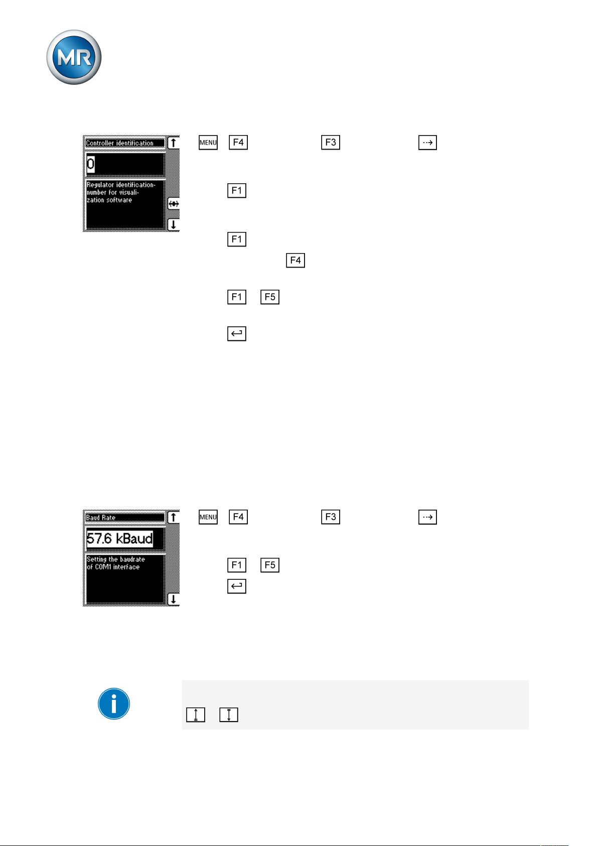
8 Operation
To set the device ID, proceed as follows:
1. > Configuration > General > Press until the desired pa-
rameter is displayed.
ð Regulator ID.
2. Press to change the first digit.
ð If you wish to enter a multi-digit sequence, proceed to step 3. If you do
not wish to enter additional digits, proceed to step 7.
3. Press (digit > 9) until another digit position appears.
4. If necessary, press in order to highlight the digit position.
ð The required digit is highlighted and can be changed.
5. Press or to change the digit.
6. Repeat steps 3 to 5 until all required digits have been entered.
7. Press .
ð The device ID is set.
8.2.2 Setting the baud rate
You can use this parameter to set the COM1 interface's baud rate. You can
select the following options:
▪ 9.6 kilobaud
▪ 19.2 kilobaud
▪ 38.4 kilobaud
▪ 57.6 kilobaud
To set the baud rate, proceed as follows:
1. > Configuration > General > Press until the desired pa-
rameter is displayed.
ð Baud rate.
2. Press or to select the required baud rate.
3. Press .
ð The baud rate is set.
8.2.3 Setting the switching pulse time
You can use this parameter to set the duration of the switching pulse for the
motor-drive unit.
If you set the switching pulse time to 0s, the motor-drive unit is activated
with a continuous signal. The signal then remains active for as long as the
or keys are pressed.
Maschinenfabrik Reinhausen GmbH 201950 2117246/05 ENTAPCON®230 basic
Page 51

8 Operation
Switching pulse in normal
mode
If you set the switching pulse time to 1.5seconds for example, after the set
delay time T1 or delay time T2 there will be a switching pulse of 1.5sec-
onds .
The waiting time between 2 consecutive switching pulses corresponds to the
set delay time T1 or delay time T2 .
Figure32: Switching pulse time in normal mode
1 Set delay time T1 or T2 2 Set switching pulse time (for exam-
ple 1.5seconds)
If the motor-drive unit does not start with the factory setting (1.5seconds),
you need to extend the raise switching pulse time / lower switching pulse
time.
Maschinenfabrik Reinhausen GmbH 2019 512117246/05 EN TAPCON®230 basic
Page 52

8 Operation
Switching pulse for rapid
return control
If you set the raise switching pulse time or lower switching pulse time to
1.5seconds, for example , the next earliest switching pulse occurs in rapid
return control mode 1.5 seconds after the previous switching pulse
ended.
Figure33: Switching pulse in rapid return control mode
1 Start of first raise switching pulse/
lower switching pulse
2 Set switching pulse time (for exam-
ple 1.5seconds)
To set the pulse duration, proceed as follows:
1. > Configuration > General > Press until the desired pa-
rameter is displayed.
ð R/L pulse duration.
2. Press or to select the pulse duration you want.
3. Press .
ð The R/L pulse duration is now set.
8.2.4 Setting operations counter
The device's operations counter is automatically increased with every tapchange operation. You can use this parameter to set the number of tapchange operations for comparing with the operations counter of the motordrive unit, for example.
To ensure correct operation counter function, the Motor running signal of the
motor-drive unit must be connected with a configurable input (GPI 1...6) and
then the Motor running function assigned to this input.
3 Earliest time for the next raise
switching pulse/lower switching
pulse (for example 1.5seconds)
Maschinenfabrik Reinhausen GmbH 201952 2117246/05 ENTAPCON®230 basic
Page 53

8 Operation
To set the operations counter, proceed as follows:
1. > Configuration > General > Press until the desired parameter is displayed.
ð Operations counter.
2. Press to highlight a digit.
ð The desired position is highlighted and the value can be changed.
3. Press to increase the value or to reduce it.
4. Press .
ð The operations counter is set.
8.2.5 Dimming display
You can use this parameter to activate or deactivate automatic display dimming. You can select the following options:
▪ On: The display is automatically dimmed if no key is pressed for 15min-
utes. The display returns to full brightness by pressing any key.
▪ Off: Automatic display dimming is deactivated.
Activating this function extends the display's service life.
To activate/deactivate automatic display dimming, proceed as follows:
1. Press > Configuration > General > until the desired parameter is displayed.
ð Display off.
2. Press or to activate/deactivate automatic dimming.
3. Press .
ð Automatic dimming is set.
8.2.6 Activating/deactivating the automatic key lock
Activating this function automatically activates the key lock if no keys are
pressed for 15minutes. You can also lock the keys manually. This function
can be deactivated as well.
Maschinenfabrik Reinhausen GmbH 2019 532117246/05 EN TAPCON®230 basic
Page 54

8 Operation
To set the automatic key lock, proceed as follows:
1. > Configuration > General > Press until the desired parameter is displayed.
ð Key lock
2. Press or to select On or Off.
3. Press .
ð Automatic key lock is set.
8.2.7 "Function monitoring" message for monitoring messages <30 V
By default, the Function monitoring message is activated for measured voltages. This message is issued as soon as the measured voltage is under
30V for longer than the set signaling delay time.
Switched-off transformer You can suppress the message with this parameter to prevent the message
from being continuously issued when a transformer is shut off.
The device behaves as follows:
Parameter Function
On The Function monitoring message is issued after the con-
figured delay time if the measured voltage is less than
30V.
Off The Function monitoring message is suppressed if the
measured voltage is less than 30V.
Table8: Settings
Activate/deactivate
To activate/deactivate function monitoring, proceed as follows:
message
1. > Configuration > General > Press until the desired parameter is displayed.
ð Function monitoring
2. Press or to select On or Off.
3. Press .
ð The Function monitoring message for is activated/deactivated for mea-
sured voltages <30V.
Setting delay time You can configure the delay time after which the Function monitoring mes-
sage is to be issued. If you select 0, function monitoring is deactivated.
Maschinenfabrik Reinhausen GmbH 201954 2117246/05 ENTAPCON®230 basic
Page 55

8 Operation
To set the delay time for the Function monitoring message, proceed as follows:
1. > Configuration > General > Press until the desired parameter is displayed.
ð Delay function monitoring
2. Press to increase the value or to reduce it.
3. Press .
ð The delay time for the Function monitoring message is set.
8.2.8 Setting motor runtime monitoring
You can use this motor runtime parameter to set the motor runtime. The motor-drive unit's runtime can also be monitored by the device. This function is
used to identify motor-drive unit malfunctions during the tap-change operation and to trigger any actions needed.
Behavior The motor-drive unit issues the Motor-drive unit running signal during the
Parameterizing control
input
tap-change operation. This signal is present until the tap-change operation is
complete. The device compares the duration of this signal with the set motor
runtime. If the set motor runtime is exceeded, the device triggers the following actions:
1. Motor runtime monitoring message is issued
2. Continuous signal via output relay Motor-drive unit runtime exceeded (optional)
3. Pulse signal via Trigger motor protective switch output relay (optional)
To use runtime monitoring, you need to correctly wire the corresponding
control input and parameterize to Motor running. The motor runtime must
also be set.
Maschinenfabrik Reinhausen GmbH 2019 552117246/05 EN TAPCON®230 basic
Page 56
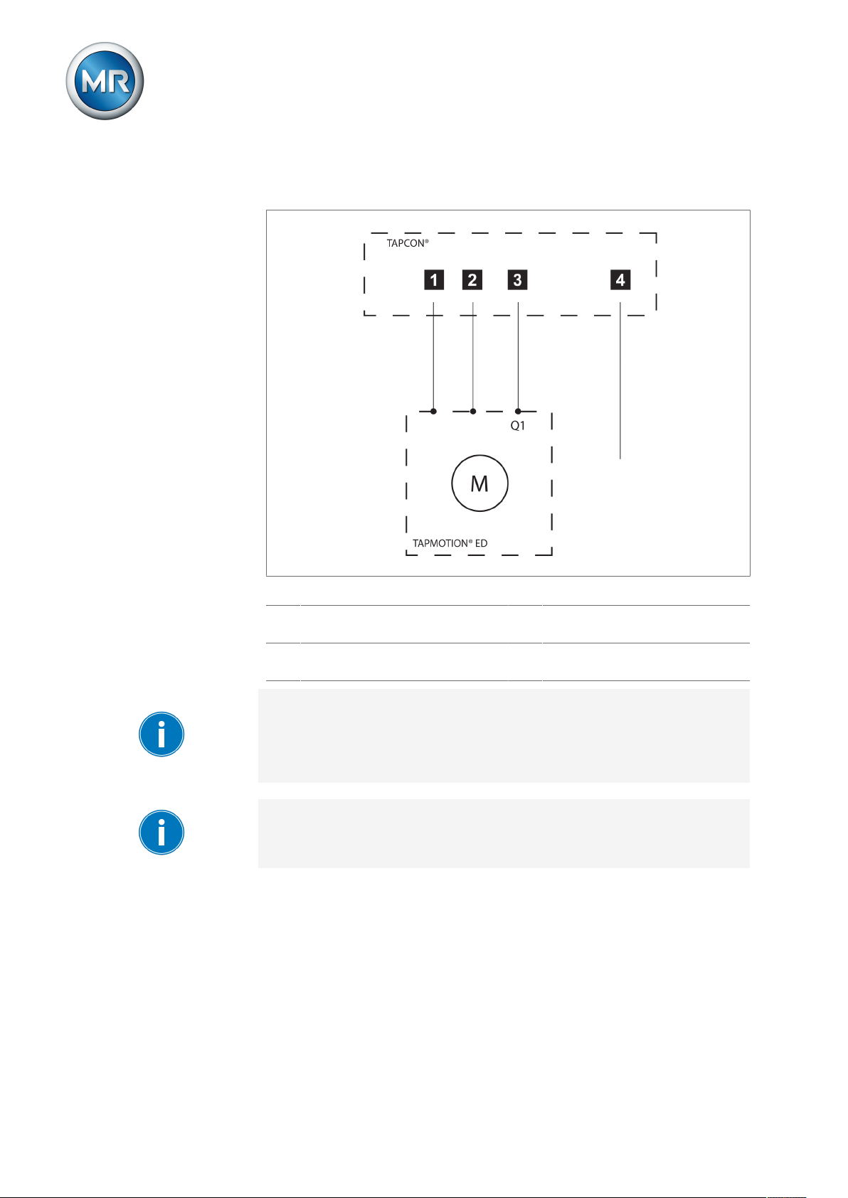
8 Operation
Wiring control input/output
relay
If you want to monitor the motor runtime, the device and motor-drive unit
must be connected and parameterized as shown below.
Figure35: Wiring for motor runtime monitoring
1 Motor running control input I/O 3 Motor protective switch tripped
GPO output relay (optional)
2 Motor protective switch triggered
control input I/O (optional)
4 Motor runtime exceeded GPO out-
put relay (optional)
If you want to use the output relay, the feedback from the motor-drive unit
Motor protective switch triggered must be wired to a control input and parameterized. This message resets the Motor runtime exceeded output relay
when the motor protective switch is switched back on and activates the Mo-
tor protective switch triggered message.
If the runtime monitoring is set to "0.0s", this equates to it being switched
off.
Maschinenfabrik Reinhausen GmbH 201956 2117246/05 ENTAPCON®230 basic
Page 57

8 Operation
To set the motor runtime, proceed as follows:
1. > Configuration > General > Press until the desired parameter is displayed.
ð Motor runtime.
2. Press to highlight the position.
ð The desired position is highlighted and the value can be changed.
3. Press to increase the value or to reduce it.
4. Press .
ð The motor runtime is set.
8.2.9 Activate manual mode/auto mode
This parameter can be used to activate the Manual or Automatic operation
modes. This parameter has the same functions as the and keys.
Parameter Function
Manual Device is no longer controlling automatically.
You can set or change parameters manually.
You can control the motor-drive unit using the con-
trol panel.
Auto The device is controlling the voltage automatically.
You cannot set or change any parameters.
You cannot control the motor-drive unit using the
control panel.
Table9: Adjustable parameters
To select the operating mode, proceed as follows:
1. > Configuration > General > Press until the desired parameter is displayed.
ð Manual/Automatic
2. Press or to select the operating mode you want.
3. Press .
ð The operating mode is set.
Maschinenfabrik Reinhausen GmbH 2019 572117246/05 EN TAPCON®230 basic
Page 58

8.2.10 Activating Local/Remote
This parameter can be used to activate the Local or Remote operation
modes. This parameter has the same functions as the keys.
Parameter Function
Local You can operate the device using the control panel.
Remote You can operate the device using an external con-
Table10: Adjustable parameters
To activate Manual or Automatic operating mode, proceed as follows:
1. > Configuration > General > Press until the desired parameter is displayed.
2. Local/Remote
8 Operation
trol level.
Manual operation is disabled.
3. Press or to select the operating mode you want.
4. Press .
ð The operating mode is set.
8.2.11 Setting the COM1 password
You can use this parameter to enter a password for the COM1 front interface. This enables you to protect the device against unauthorized access via
these interfaces. If a COM1 password is assigned, you must first enter the
correct password to establish a connection via the interfaces.
Note the following information:
▪ The password must be at least 1 character long and must not exceed 8
characters. If you enter an empty password (only an end marker), then the
COM1 password is deactivated.
▪ You can enter alphanumeric characters (A to Z, a to z, 0 to 9) and an end
marker (space).
▪ If you want to use a password with fewer than 8 characters, you must se-
lect the end marker after the last character of your password.
▪ Once you save the password, the display changes to xxxxxxxx. The
password is only displayed in plain text during text input.
Maschinenfabrik Reinhausen GmbH 201958 2117246/05 ENTAPCON®230 basic
Page 59

8 Operation
Proceed as follows to set the COM1 password:
1. > Configuration > General > Press until the desired parameter is displayed.
ð COM1 password.
2. Enter the current COM1 password. Press or to change a character and to select the next character.
3. Press .
ð The Parallel operation active LED flashes. You can establish a connec-
tion via the front interface or enter a new password.
4. Press or to change a character and to select the next character.
5. Press .
ð The COM1 password is set. The display changes to xxxxxxxx.
8.2.12 Setting the password duration
You can use this parameter to set the period for which the password is active once it has been entered. If the password is active, the Parallel opera-
tion active LED flashes.
If you establish a connection via the COM1 front interface, the password remains active for as long as data is being transferred via the interface. The
set password duration expires the moment that no more data is transmitted.
To set the password duration, proceed as follows:
1. > Configuration > General > Press until the desired parameter is displayed.
ð Password duration.
2. Press or to increase or decrease the value.
3. Press .
ð The password duration is set.
8.3 NORMset
NORMset mode is used for quickly starting voltage regulation. In NORMset
mode, the bandwidth and delay time parameters are automatically adapted
to the requirements of the grid.
To start NORMset mode, you must set the following parameters:
▪ Normset activation
▪ Desired value 1
Maschinenfabrik Reinhausen GmbH 2019 592117246/05 EN TAPCON®230 basic
Page 60

8 Operation
▪ Primary voltage
▪ Secondary voltage
Line drop compensation cannot be performed in NORMset mode.
Set the following parameters to operate the device in NORMset mode.
Activating/deactivating NORMset
You can use this parameter to activate NORMset mode.
A manual tap-change operation is required to activate NORMset. This is
how the voltage regulator determines the bandwidth required.
If the transformer is switched off, another manual tap-change operation is
required.
To activate/deactivate NORMset mode, proceed as follows:
1. > NORMset
ð NORMset activation.
2. Press or to activate NORMset by selecting On or to deactivate
NORMset by selecting Off.
3. Press .
ð NORMset is activated/deactivated.
Setting the primary voltage
With this parameter, you can set the voltage transformer's primary voltage.
To set the primary voltage, proceed as follows:
1. > NORMset > Press until the desired parameter is displayed.
ð Primary voltage.
2. Press to increase the value or to reduce it.
3. Press .
ð The primary voltage is set.
Setting the secondary voltage
With this parameter, you can set the voltage transformer's secondary voltage.
Maschinenfabrik Reinhausen GmbH 201960 2117246/05 ENTAPCON®230 basic
Page 61

8 Operation
To set the secondary voltage, proceed as follows:
1. > NORMset > Press until the desired parameter is displayed.
ð Secondary voltage.
2. Press to increase the value or to reduce it.
3. Press .
ð The secondary voltage is set.
Setting desired value 1
With this parameter, you can set the desired value for automatic voltage regulation. You can enter the desired value in V or in kV. If you enter the desired value in V, the value relates to the voltage transformer's secondary
voltage. If you set the desired value in kV, the value relates to the voltage
transformer's primary voltage.
Settings in kV are only possible if you have previously entered the parameters for primary and secondary voltage.
To set the desired value, proceed as follows:
1. > NORMset > Press until the desired parameter is displayed.
ð Desired value 1.
2. Press to increase the value or to reduce it.
3. Press .
ð The desired value is set.
8.4 Control parameters
All of the required for the regulation function are described in this section.
For voltage regulation, you can set the following parameters:
▪ Desired values 1…3
▪ Bandwidth
▪ Delay time T1
▪ Control response T1
▪ Delay time T2
For voltage regulation, you can set delay time T1 and also delay time T2.
The following sections describe how the regulation function responds in both
cases:
Maschinenfabrik Reinhausen GmbH 2019 612117246/05 EN TAPCON®230 basic
Page 62

Behavior only with delay time T1
8 Operation
If the measured voltage U
is within the set bandwidth , no control
actual
commands are issued to the motor-drive unit for the tap-change operation.
Control commands will also not be issued to the motor-drive unit if the mea-
sured voltage returns to the tolerance bandwidth within the set delay time
T1 . However, if the measured voltage deviates from the set bandwidth for
a long period , a tap-change command occurs after expiration of the
set delay time T1. The on-load tap-changer carries out a tap-change in a
raise or lower direction to return to the tolerance bandwidth.
Figure38: Behavior of the regulation function with delay time T1
1 +B%: Upper limit 4 Set delay time T1
2 U
: Desired value 5 U
desired
: Measured voltage
actual
3 -B%: Lower limit 6 B%: Tolerance bandwidth
A U
C U
is outside the bandwidth. De-
actual
lay time T1 starts.
is outside the bandwidth. De-
actual
lay time T1 starts.
B U
is within the bandwidth be-
actual
fore delay time T1 is complete.
D U
is still outside the bandwidth
actual
when delay time T1 is complete.
Tap-change operation is initiated.
Behavior with delay times T1 and T2
Delay time T2 can be used to correct major control deviations more quickly.
Ensure that you set a lower value in the "Delay time T2" parameter than in
the "Delay time T1" parameter.
If the measured voltage U
deviates from the set bandwidth for a long
actual
period , a control impulse is output to the motor-drive unit after the set delay time T1 . If the measured voltage U
is still outside the bandwidth,
actual
Maschinenfabrik Reinhausen GmbH 201962 2117246/05 ENTAPCON®230 basic
Page 63

8 Operation
delay time T2 starts once delay time T1 is complete. Once delay time T2
is complete, a control impulse is again output to the motor-drive unit for the
tap change to return to the tolerance bandwidth.
Figure39: Behavior of the regulation function with delay times T1 and T2
1 +B%: Upper limit 4 Set delay times T1 and T2.
2 U
: Desired value 5 U
desired
3 -B%: Lower limit 6 B%: Tolerance bandwidth
A U
is outside the bandwidth. De-
actual
lay time T1 starts.
C Delay time T2 complete. Tap
change triggered.
The following sections describe how to set the relevant control parameters.
8.4.1 Setting desired value 1...3
You can use this parameter to set up to 3 desired voltage values U
desired voltage value is specified as a fixed value. The desired value 1 is the
default desired value. Desired values 2 and 3 are activated if there is a continuous signal at factory-preset control inputs X4:17 or X4:18 provided you
have programmed these previously. If there is a signal at several control inputs at the same time, desired value 2 is activated.
: Measured voltage
actual
B Delay time T1 complete. Tap
change triggered.
Ref
. The
Maschinenfabrik Reinhausen GmbH 2019 632117246/05 EN TAPCON®230 basic
Page 64
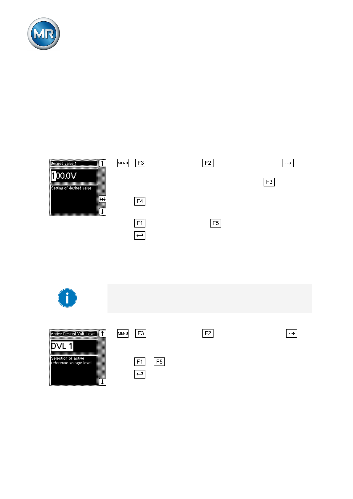
8 Operation
Options for setting the
desired values
Reference of kV and V for
voltage transformer
The device provides the following ways of changing the desired voltage
value during operation:
▪ Using the control parameters menu item via the operating screen
▪ Using binary inputs
▪ Using control system protocols if a communication card is ready for opera-
tion
Desired values set in kV refer to the primary voltage of the voltage transformer. Desired values set in V refer to the secondary voltage of the voltage
transformer. The transformer data must be entered correctly for this display.
To set the desired value, proceed as follows:
1. > Control parameter > voltage regulator > Press until
the desired parameter is displayed.
2. If you have already entered the transformer data, press to select the
unit you want: "V" or "kV".
3. Press to highlight the position.
ð The desired position is highlighted and the value can be changed.
4. Press to increase the value or to reduce it.
5. Press .
ð The desired value is set.
8.4.2 Selecting a desired value
You can use this parameter to select the active desired value 1, 2 or 3.
If you select the desired value using appropriately configured GPIs, this parameter's setting is ignored. Refer to the Configuration [►Section 8.8, Page
88] section for more information about GPI configuration.
Proceed as follows to select a desired value:
1. > Control parameter > Voltage regulation > Press until
the desired parameter is displayed.
ð Desired value selection
2. Press or to select an active desired value.
3. Press .
ð The selected desired value is active.
Maschinenfabrik Reinhausen GmbH 201964 2117246/05 ENTAPCON®230 basic
Page 65

8 Operation
8.4.3 Bandwidth
You can use this parameter to set the maximum permissible deviation in
measured voltage U
The following sections describe how you determine and set the bandwidth
required.
8.4.3.1 Determining bandwidth
In order to set the correct value, the transformer's step voltage and nominal
voltage must be known.
. The deviation relates to the activated desired value.
Act
Too small/large a
bandwidth
You have to set the bandwidth in such a way that the output voltage of the
transformer (U
) returns to within the specified tolerance bandwidth after
Act
the tap change. If too small a bandwidth is defined, the output voltage exceeds the bandwidth selected and the device immediately issues a tapchange command in the opposite direction. If a very large bandwidth is selected, this results in a major control deviation.
The following value is recommended for the bandwidth setting:
Figure41: Recommended bandwidth
U
U
U
Step voltage of tap position n-1
n-1
Step voltage of tap position n
n
Nominal voltage
nom
The following transformer values are used to determine the recommended
bandwidth:
Nominal voltage U
Step voltage in tap position 4 U
Step voltage in tap position 5 U
= 11,000V
nom
= 11,275V
Step4
= 11,000V
Step5
The following section describes how you can set the bandwidth.
Maschinenfabrik Reinhausen GmbH 2019 652117246/05 EN TAPCON®230 basic
Page 66
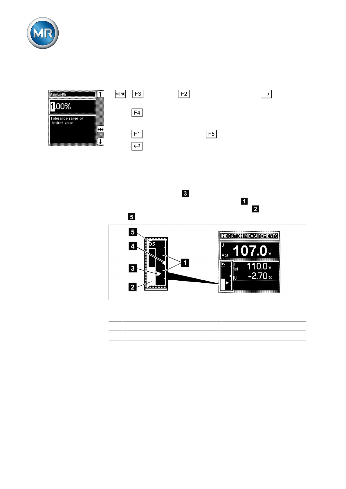
8.4.3.2 Setting the bandwidth
To enter the determined bandwidth, proceed as follows:
1. > Parameter > Control parameter > Press until the desired parameter is displayed.
2. Press to highlight the position.
ð The desired position is highlighted and the value can be changed.
3. Press to increase the value or to reduce it.
4. Press .
ð The bandwidth is set.
8.4.3.3 Visual display
The deviation from the set bandwidth is shown visually in the device's display. The measured voltage highlighting shows whether the measured
voltage is above, within or below the set bandwidth . Progress of delay
time T1 is indicated by the gradual filling of the time bar . The seconds
display above this indicates the remaining delay time T1.
8 Operation
Figure42: Visual display of deviation from desired value
1 Bandwidth (upper and lower limit) 4 Desired voltage value U
2 Time bar for delay time T1 5 Remaining delay time T1
3 Measured voltage U
8.4.4 Setting delay time T1
Use this parameter to set delay time T1. This function delays the issuing of a
tap-change command for a defined period. This prevents unnecessary tapchange operations if the tolerance bandwidth is exited.
desired
actual
Maschinenfabrik Reinhausen GmbH 201966 2117246/05 ENTAPCON®230 basic
Page 67
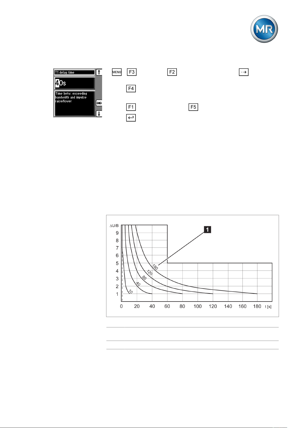
8 Operation
To set the delay time T1, proceed as follows:
1. > Parameter > Control parameter > Press until the desired parameter is displayed.
2. Press to highlight the position.
ð The desired position is highlighted and the value can be changed.
3. Press to increase the time or to reduce it.
4. Press .
ð The delay time T1 is set.
8.4.5 Setting control response T1
The control response T1 can be set to linear or integral.
Linear control response T1 With linear control response, the device responds with a constant delay time
regardless of the control deviation.
Integral control responseT1With integral control response, the device responds with a variable delay
time depending on the control deviation. The greater the control deviation
(ΔU) in relation to the set bandwidth (B), the shorter the delay time. The delay time can therefore be reduced down to 1 second. This means that the
device responds faster to large voltage changes in the grid. Regulation accuracy improves as a result but the frequency of tap-changes increases too.
Figure43: Diagram showing integral control response
ΔU/B Control deviation "ΔU" as % of desired value as ratio to the set bandwidth
"B" as % of desired value
1 "Delay time T1" parameter
Maschinenfabrik Reinhausen GmbH 2019 672117246/05 EN TAPCON®230 basic
Page 68
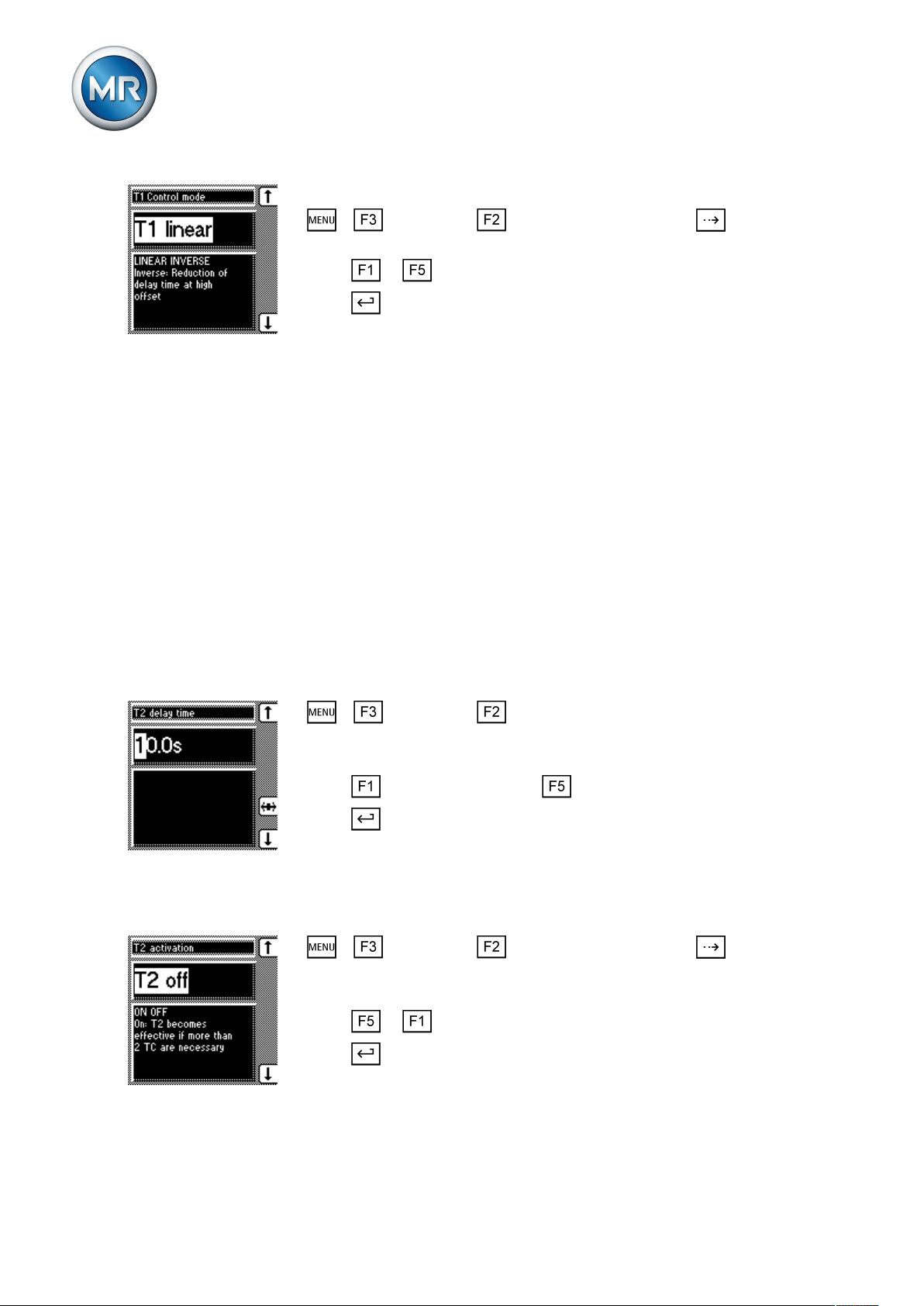
To set the control response T1, proceed as follows:
1. > Parameter > Control parameter > Press until the desired parameter is displayed.
2. Press or to set the response you want.
3. Press .
ð The control response T1 is set.
8.4.6 Setting delay time T2
With this parameter, you can set delay time T2. Delay time T2 is used to
compensate for large control deviations faster.
The delay time T2 only takes effect if more than one tap-change operation is
required to return the voltage to within the set bandwidth. The first output
pulse occurs after the set delay time T1. After the set tap-change delay time
T2 has elapsed, additional pulses occur in order to correct the existing control deviation.
8 Operation
The following requirements must be noted to set delay time T2:
▪ The delay time T2 must be greater than the switching pulse time.
▪ The delay time T2 must be greater than the maximum operating time of
the motor-drive unit.
▪ The delay time T2 must be less than the value set for delay time T1.
To set the delay time T2, proceed as follows:
1. > Parameter > Control parameter > Press until the desired
parameter is displayed.
ð Delay time T2.
2. Press to increase the time or to reduce it.
3. Press .
ð The delay time T2 is set.
Activating/deactivating delay time T2
To activate/deactivate delay time T2 , proceed as follows:
1. > Parameter > Control parameter > Press until the desired parameter is displayed.
ð T2 activation.
2. Press or to activate/deactivate T2.
3. Press .
ð The delay time T2 is activated/deactivated.
Maschinenfabrik Reinhausen GmbH 201968 2117246/05 ENTAPCON®230 basic
Page 69

8 Operation
8.5 Limit values
In the Limit values menu item, you can set all the parameters needed for
limit value monitoring as relative or absolute values. You can set three limit
values:
▪ Undervoltage U<
▪ Overvoltage U>
▪ Overcurrent I>
Limit value monitoring is used to reduce damage to the system periphery.
The following sections describe how you can set the parameters.
8.5.1 Setting undervoltage monitoring U<
You can use these parameters to set the limit values for an undervoltage.
Undervoltage monitoring prevents tap-change operations if there is a power
cut.
Maschinenfabrik Reinhausen GmbH 2019 692117246/05 EN TAPCON®230 basic
Page 70

8 Operation
Behavior
If the measured voltage U
falls below the set limit value , the red
actual
LED U< lights up . The switching pulses to the motor-drive unit are blocked
at the same time provided you have activated the blocking undervoltage U<
parameter. Once the set signaling delay time [►Section , Page 71] has
passed, the signaling relay activates. The Undervoltage U< message ap-
pears in the display. The message is reset as soon as the measured voltage
U
again exceeds the limit value for undervoltage . If the measured volt-
actual
age U
falls below 30V (for example when the transformer is switched
actual
off), the undervoltage message is also displayed. You can however suppress [►Section , Page 72] this message.
Figure44: Response to value falling below limit value
1 +B%: Upper limit 7 U
2 U
: Desired value A Value falls below limit value
desired
: Measured voltage
actual
3 -B%: Lower limit B Undervoltage U< message is dis-
played
4 Set limit value for undervoltage U< C Voltage falls below 30V
5 Limit value for suppressing alarms
D Voltage exceeds 30V again
below 30V
6 Set signaling delay time for limit
E Value exceeds limit value
value for undervoltage U<
Setting undervoltage monitoring U< in %
Use the parameter to set the limit value as a relative value.
Maschinenfabrik Reinhausen GmbH 201970 2117246/05 ENTAPCON®230 basic
Page 71
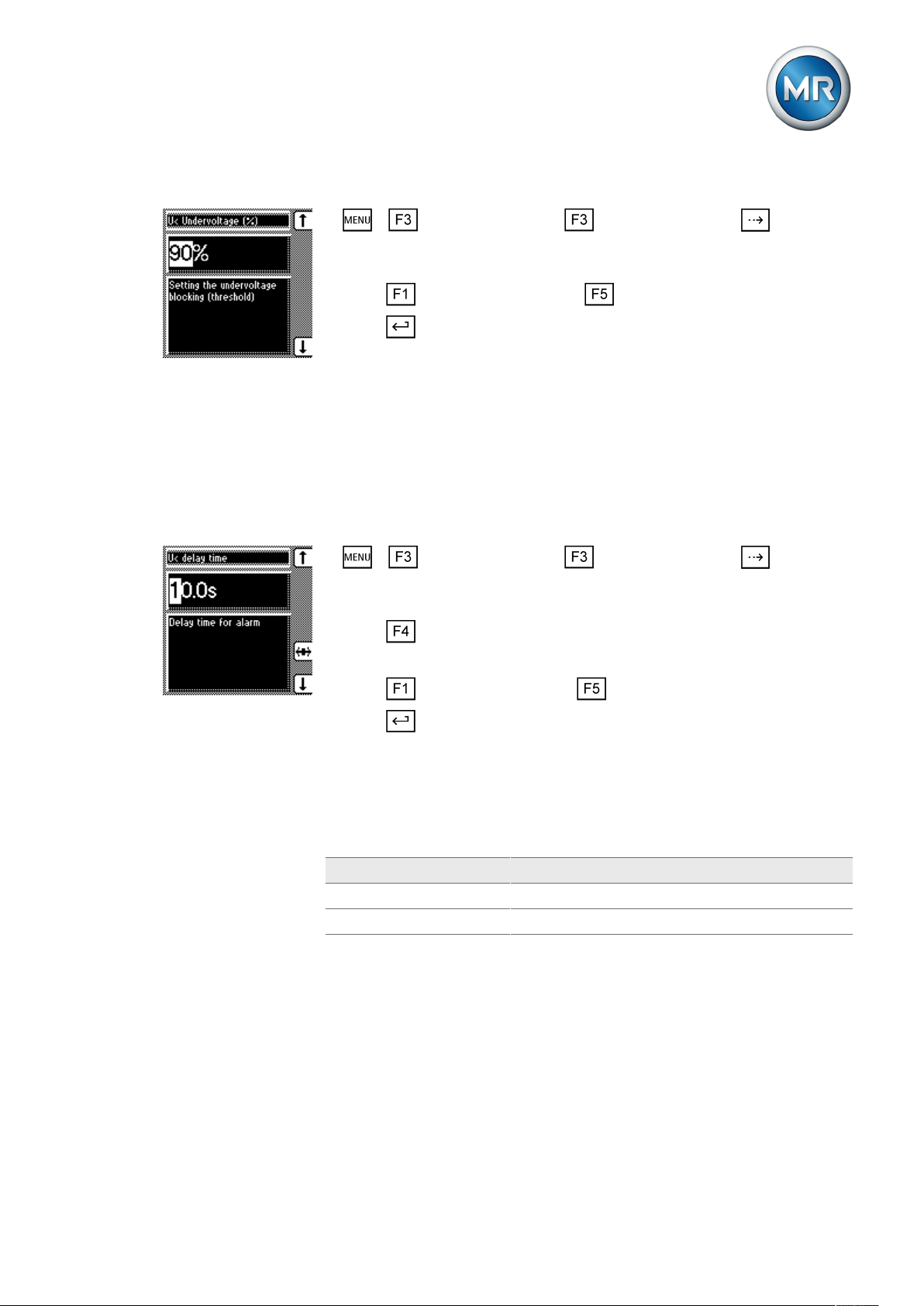
8 Operation
To set the limit value for undervoltage U< as %, proceed as follows:
1. > Control parameter > Limit values > Press until the
desired parameter is displayed.
ð U< Undervoltage (%)
2. Press to increase the value or to reduce it.
3. Press .
ð The limit value for undervoltage U< is set.
Setting signaling delay for undervoltage U<
You can use this parameter to set the delay time after which the Undervoltage relay is to activate and the event message appear on the display. This
can be used to prevent messages from being issued when the value briefly
falls below the limit value. The undervoltage LED always lights up immediately regardless.
To set the delay time for this message, proceed as follows:
1. > Control parameter > Limit values > Press until the
desired parameter is displayed.
ð U< Delay
2. Press to highlight the position.
ð The desired position is highlighted and the value can be changed.
3. Press to increase the time or to reduce it.
4. Press .
ð The signaling delay time for undervoltage U< is set.
Activating/deactivating undervoltage blocking
You can use this parameter to set how the device behaves if the voltage falls
below the undervoltage limit. You can select the following options:
Setting Function
On Automatic regulation is blocked.
Off Automatic regulation remains active.
Table11: Behavior
Maschinenfabrik Reinhausen GmbH 2019 712117246/05 EN TAPCON®230 basic
Page 72

8 Operation
To activate/deactivate the undervoltage blocking, proceed as follows:
1. > Control parameter > Limit values > Press until the
desired parameter is displayed.
ð U< blocking.
2. Press for On setting or for Off setting.
3. Press .
ð Undervoltage blocking is activated/deactivated.
Activating/deactivating message for voltages below 30V
You can use this parameter to set whether the Undervoltage message is to
be suppressed at a measured value of less than 30V. This setting is used to
ensure that no event message appears when the transformer is switched off.
You can select the following options:
Setting Function
On The Undervoltage message is also displayed when
the measured value is less than 30V.
Off The Undervoltage message is no longer displayed
when the measured value is less than 30V.
Table12: Response
To activate/deactivate the message, proceed as follows:
1. > Control parameter > Limit values > Press until the
desired parameter is displayed.
ð U< also under 30V.
2. Press for On setting or for Off setting.
3. Press .
ð The message is activated/deactivated.
8.5.2 Setting overvoltage monitoring U>
You can use these parameters to set the limit values for overvoltage monitoring. This overvoltage monitoring triggers tap-change operations to return
to the desired operating status. If the operating status can no longer be corrected, a message is triggered by the Function monitoring relay.
Maschinenfabrik Reinhausen GmbH 201972 2117246/05 ENTAPCON®230 basic
Page 73

8 Operation
Response to high-speed
return
If the measured voltage U
exceeds the set limit value , the red LED U>
actual
and associated signaling relay activate. The Overvoltage U> message appears in the display. At the same time, the high-speed return function is acti-
vated without delay time T1. Once the set switching pulse time has
passed, the tap position is lowered by activating the motor-drive unit until
the measured voltage U
again falls below the limit value . The Over-
actual
voltage U> message is reset.
Response to overvoltage
blocking
Figure45: Response to limit value being exceeded
1 Set limit value for overvoltage U> 6 U
2 +B%: Upper limit A Value exceeds limit value
3 U
4 -B%: Lower limit C High-speed return is started (lower
5 Set switching pulse time
: Desired value B Value falls below limit value
desired
: Measured voltage
actual
tap-change)
If you activated the overvoltage blocking, all switching pulses to the motordrive unit are blocked when a limit value is exceeded. At the same time, the
red LED U> lights up and the Overvoltage U> message is displayed. As
soon as the measured voltage U
has again fallen below the limit value,
actual
blocking and the message are reset.
The following sections describe how you can set the parameters for the
overvoltage U> limit value.
Maschinenfabrik Reinhausen GmbH 2019 732117246/05 EN TAPCON®230 basic
Page 74

8 Operation
Setting overvoltage U> as %
The limit value is entered as a relative value (%) of the set desired value. To
set the limit value, proceed as follows:
1. > Control parameter > Limit values > Press until the
desired parameter is displayed.
ð U> Overvoltage (%)
2. Press to increase the value or to reduce it.
3. Press .
ð The limit value is set.
Activating overvoltage blocking/high-speed return
You can use this parameter to set how the device responds to overvoltage.
The following settings are possible:
Setting Behavior
On During overvoltage, the device blocks all switch pulses
to the motor-drive unit.
Off In the event of overvoltage, a high-speed return is un-
dertaken until the value again falls below the limit value.
Table13: Possible settings
To set the device's response to overvoltage, proceed as follows:
1. > Control parameter > Limit values > Press until the
desired parameter is displayed.
ð Overvolt. blocking U>.
2. Press or to set the option you want.
3. Press .
ð The response is set.
8.5.3 Setting overcurrent monitoring I>
You can use this parameter to set the limit value for overcurrent to prevent
tap-change operations in the event of excess load currents.
If the measured current exceeds the set limit value, the red LED I> lights up.
The Overcurrent message appears in the display. The device's output pulses
are blocked at the same time.
Maschinenfabrik Reinhausen GmbH 201974 2117246/05 ENTAPCON®230 basic
Page 75
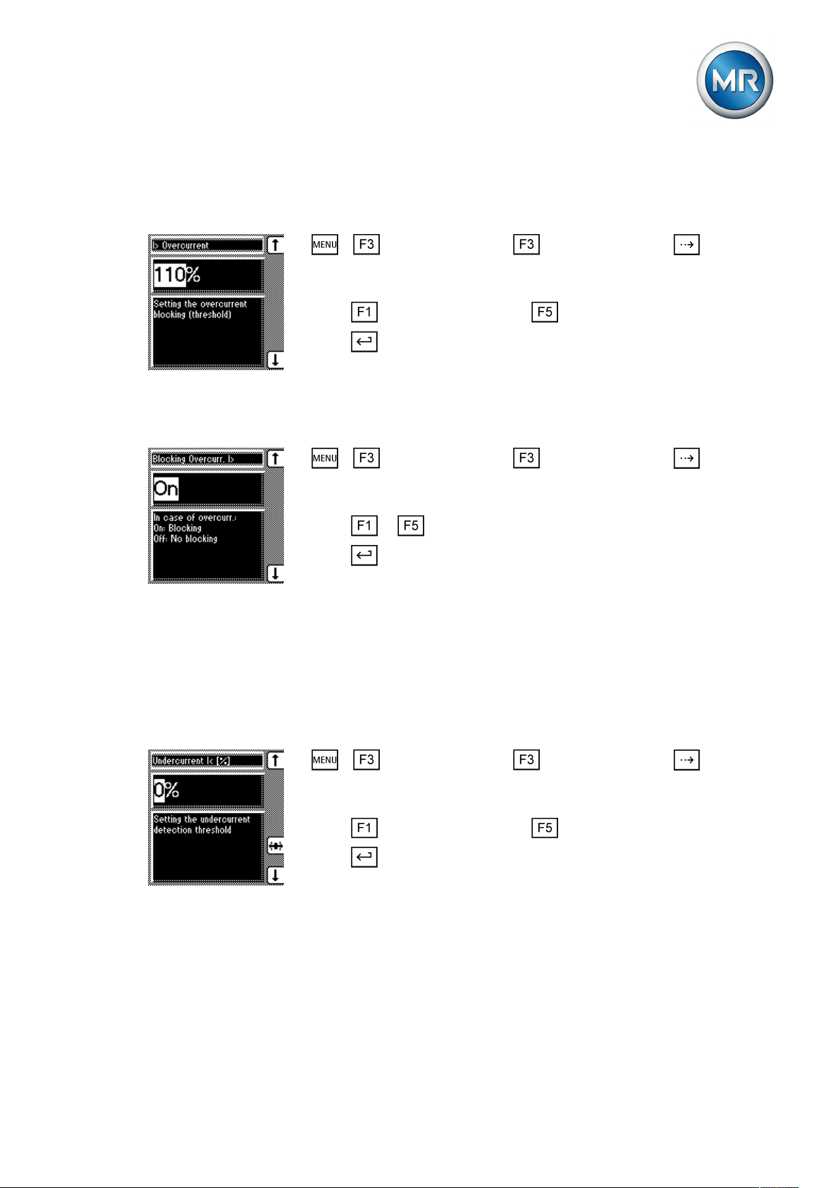
8 Operation
Setting overcurrent I> as %
To set the limit value I> overcurrent for overcurrent blocking, proceed as follows:
1. > Control parameter > Limit values > Press until the
desired parameter is displayed.
ð Overcurrent I>
2. Press to increase the value or to reduce it.
3. Press .
ð The limit value is set.
Activating/deactivating overcurrent blocking
To activate/deactivate overcurrent blocking, proceed as follows:
1. > Control parameter > Limit values > Press until the
desired parameter is displayed.
ð Blocking Overcurr. I>
2. Press or to activate (ON)/deactivate (OFF) overcurrent blocking.
3. Press .
ð The overcurrent blocking is activated/deactivated.
8.5.4 Set undercurrent monitoring I<
These parameters are used to set undercurrent monitoring. As soon as the
measured current falls below the set limit value, control is blocked.
Setting undercurrent I<
To set the limit value for undercurrent monitoring, proceed as follows:
1. > Control parameter > Limit values > Press until the
desired parameter is displayed.
ð Undercurrent I< [%]
2. Press to increase the value or to reduce it.
3. Press .
ð The I< undercurrent limit value is set.
Maschinenfabrik Reinhausen GmbH 2019 752117246/05 EN TAPCON®230 basic
Page 76

Activating/deactivating I< undercurrent blocking
To activate/deactivate undercurrent monitoring, proceed as follows:
1. > Control parameter > Limit values > Press until the
desired parameter is displayed.
ð Blocking undercurrent I>.
2. Press or to activate (ON)/deactivate (OFF) undercurrent blocking.
3. Press .
ð The I< undercurrent blocking is activated/deactivated.
8.5.5 Activate/deactivate active power monitoring
This parameter can be used to set active power monitoring. If blocking is activated, the control is blocked if a negative active power flow is detected.
However, this is only possible if the current transformer connection is connected and correctly set. When regulator blocking is deactivated, then the
sign of the active power does not affect the regulation.
8 Operation
To activate/deactivate regulator blocking, proceed as follows:
1. > control parameter > Compensation > Press until the
desired parameter is displayed.
ð Neg. active power block.
2. Press or to select the option you want.
3. Press .
ð Blocking the regulator with negative active power is activated/deactivated.
8.6 Compensation
You can use the "Compensation" function to compensate for the load-dependent voltage drop between the transformer and consumer. The device provides 2 methods of compensation for this purpose:
▪ R&X compensation (line drop compensation)
▪ Z compensation
8.6.1 Line drop compensation
R&X compensation (LDC) requires exact cable data. Line voltage drops can
be compensated very accurately using LDC.
Maschinenfabrik Reinhausen GmbH 201976 2117246/05 ENTAPCON®230 basic
Page 77
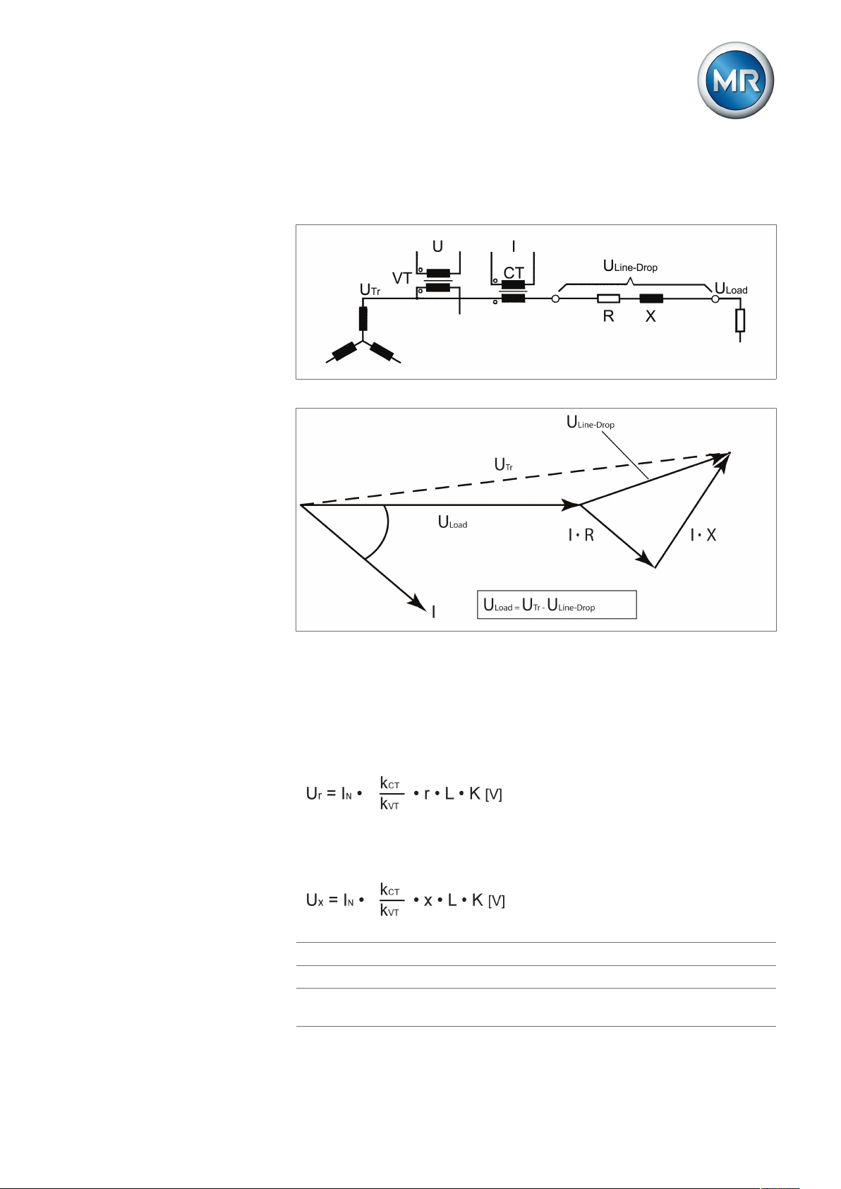
8 Operation
To set R&X compensation correctly, you need to calculate the ohmic and inductive voltage drop in V with reference to the secondary side of the voltage
transformer. You also need to correctly set the transformer circuit used.
Figure46: Equivalent circuit
Figure47: Phasor diagram
You can calculate the ohmic and inductive voltage drop using the following
formulas. This voltage drop calculation relates to the relativized voltage on
the secondary side of the voltage transformer.
Formula for calculating the ohmic voltage drop:
Formula for calculating the inductive voltage drop:
U
r
U
x
I
N
Voltage drop in V due to ohmic line resistance
Voltage drop in V due to inductive line resistance
Nominal current (amps) of selected current-transformer con-
nection on device:1 A; 5 A
Maschinenfabrik Reinhausen GmbH 2019 772117246/05 EN TAPCON®230 basic
Page 78

8 Operation
k
CT
k
VT
r Ohmic resistance load in Ω/km per phase
x Inductive resistance load in Ω/km per phase
L Length of line in km
K Nominal current factor
Current transformer ratio
Voltage transformer ratio
Selecting the line drop compensation
To select the line drop compensation, proceed as follows:
► > Control parameter > Compensation method.
ð Compensation method.
ð Press or until the LDC option is displayed.
1. Press .
2. The line drop compensation is selected.
The following sections describe how you can set the parameters for the
ohmic and inductive voltage drop.
8.6.1.1 Setting the ohmic voltage drop Ur
You can use this parameter to set the ohmic voltage drop (ohmic resistance
load).
If you do not want to use line drop compensation, you have to set the value
0.0V.
To set the ohmic voltage drop Ur, proceed as follows:
ü Select the LDC compensation method.
1. > Parameter > Compensation > Press until the desired
parameter is displayed.
ð Ur line drop compensation.
2. Press to highlight the position.
ð The desired position is highlighted and the value can be changed.
3. Press to increase the value or to reduce it.
4. Press .
ð The ohmic voltage drop Ur is set.
Maschinenfabrik Reinhausen GmbH 201978 2117246/05 ENTAPCON®230 basic
Page 79

8 Operation
8.6.1.2 Setting the inductive voltage drop Ux
You can use this parameter to set the inductive voltage drop (inductive resistance load). The compensation effect can be rotated by 180° in the display
using a plus or minus sign.
If you do not want to use line drop compensation, you have to set the value
0.0V.
To set the inductive voltage drop Ux, proceed as follows:
ü Select the LDC compensation method.
1. > Parameter > Compensation > Press until the desired
parameter is displayed.
ð Ux line drop compensation.
2. Press to highlight the position.
ð The desired position is highlighted and the value can be changed.
3. Press to increase the value or to reduce it.
4. Press .
ð The inductive voltage drop Ux is set.
8.6.2 Z compensation
To keep the voltage constant for the consumer, you can use Z compensation
to activate a current-dependent increase in voltage. You can also define a
limit value to avoid excess voltage on the transformer.
Figure49: Z compensation
Maschinenfabrik Reinhausen GmbH 2019 792117246/05 EN TAPCON®230 basic
Page 80

8 Operation
To use Z compensation, you need to calculate the increase in voltage (ΔU)
taking the current into account. Use the following formula for this purpose:
∆U Voltage increase I Load current in A
UTrTransformer voltage with cur-
rent I
U
Voltage on line end with current
Load
I and on-load tap-changer in
same operating position
INNominal current of current-trans-
former connection in A (1 A; 5 A )
kCTCurrent transformer ratio
Sample calculation: UTr = 100.1V, U
I = 100A
Produces a voltage increase ∆U of 0.2%
The following sections describe how you can set the parameters you need
for Z compensation.
Select Z compensation
To select the line drop compensation, proceed as follows:
► > Control parameter > Compensation method.
ð Compensation method.
ð Press or until the Z option is displayed.
1. Press .
2. The Z compensation is selected.
The following sections describe how you can set the required parameters for
Z compensation.
8.6.2.1 Setting Z compensation
This parameter sets the voltage increase ∆U previously calculated.
= 100.0V, IN = 5A kCT = 200A/5A,
Load
If you do not want to use Z compensation, you have to set the value 0.0%.
Maschinenfabrik Reinhausen GmbH 201980 2117246/05 ENTAPCON®230 basic
Page 81
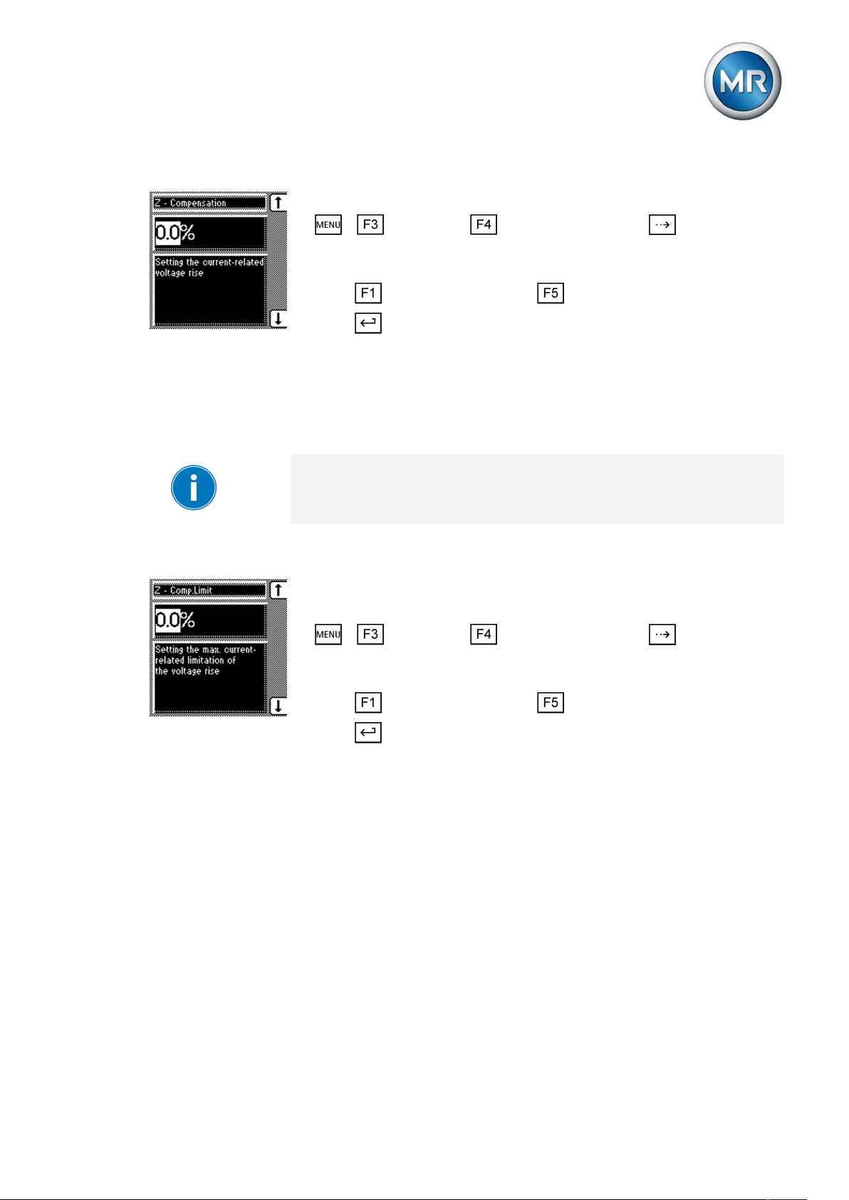
8 Operation
To set the current dependent voltage increase, proceed as follows:
ü Select Z compensation.
1. > Parameter > Compensation > Press until the desired
parameter is displayed.
ð Z compensation.
2. Press to increase the value or to reduce it.
3. Press .
ð The current-dependent voltage increase is set.
8.6.2.2 Setting the Z compensation limit value
You can use this parameter to define the maximum permissible voltage increase to avoid excess voltage on the transformer.
If you do not want to use a limit value, you have to set the value 0.0%.
To set the limit value for the current-dependent voltage increase, proceed as
follows:
ü Select Z compensation.
ü Set the "Z compensation" parameter
1. > Parameter > Compensation > Press until the desired
parameter is displayed.
ð Z comp. limit value.
2. Press to increase the value or to reduce it.
3. Press .
ð The limit value is set.
8.7 Transformer data
The transformation ratios and measuring set-up for the voltage and current
transformers used in the system can be set with the following parameters.
The device uses this information to calculate the corresponding measured
values on the primary side of the current transformer (and therefore the
transformer) from the recorded measured values. These are then displayed.
The following parameters are available for this purpose:
▪ Primary voltage
▪ Secondary voltage
▪ Primary current
Maschinenfabrik Reinhausen GmbH 2019 812117246/05 EN TAPCON®230 basic
Page 82

▪ Secondary current (current transformer connection)
▪ Transformer circuit
The measured values displayed for the device are influenced by the settings
for the above parameters. Note the table below.
Parameter set Measured value display
Primary
voltage
- Yes - - Secondary voltage
Yes Yes - - Primary voltage
Yes Yes Yes - Primary voltage
Yes Yes - Yes Primary voltage
Yes Yes Yes Yes Primary voltage
Table14: Influence of transformer data on measured value display
Secondary
voltage
Primary cur-
rent
Trans-
former con-
nection
Voltage (main
screen)
[V]
[kV]
[kV]
[kV]
[kV]
Current (main
screen)
- Secondary current
[% of connection]
- Secondary current
[% of connection]
Primary current
[A]
- Secondary current
Primary current
[A]
Secondary current
[% of connection]
Secondary current
8 Operation
Current (info
screen)
[A]
[A]
8.7.1 Setting the primary transformer voltage
This parameter can be used to set the primary transformer voltage in kV.
When you are setting the primary transformer voltage, the device shows the
primary voltage rather than the secondary voltage in the main screen and
you can also set the control parameters in kV.
If a setting of 0kV is chosen, no primary transformer voltage is displayed.
To set the primary transformer voltage, proceed as follows:
1. > Configuration > Transformer data.
ð Primary voltage.
2. Press to highlight the decimal place.
ð The decimal place is defined and the value can be changed.
3. Press to highlight the position.
ð The desired position is highlighted and the value can be changed.
4. Press to increase the value or to reduce it.
5. Press .
ð The primary transformer voltage is set.
8.7.2 Setting the secondary transformer voltage
This parameter can be used to set the secondary transformer voltage in V.
Maschinenfabrik Reinhausen GmbH 201982 2117246/05 ENTAPCON®230 basic
Page 83

8 Operation
To set the secondary transformer voltage, proceed as follows:
1. > Configuration > Transformer data > Press until the
desired parameter is displayed.
ð Secondary voltage.
2. Press to highlight the position.
ð The desired position is highlighted and the value can be changed.
3. Press to increase the value or to reduce it.
4. Press .
ð The secondary transformer voltage is set.
8.7.3 Setting primary transformer current
This parameter can be used to set the primary transformer current.
▪ When you are setting the primary transformer current, the measured value
is displayed in the main screen.
▪ If you set a value of 0, no measured value is displayed in the main screen.
Setting parameter Current feed Display
Primary current Secondary current Power connection Info screen
Primary/secondary
current
No parameterization Unknown 1A 100% 0A
No parameterization 1A 1A 1A 0A
50A Unknown 1A 100% (of primary cur-
rent)
50A 1A 1A 1A (of secondary cur-
rent)
Table15: Example of unit displayed: %/A
To set the primary transformer current, proceed as follows:
1. > Configuration > Transformer data > Press until the
desired parameter is displayed.
ð Primary current.
2. Press to highlight the position.
ð The desired position is highlighted and the value can be changed.
3. Press to increase the value or to reduce it.
Main screen
50A (of primary current)
50A (of primary current)
4. Press .
ð The primary transformer current is set.
Maschinenfabrik Reinhausen GmbH 2019 832117246/05 EN TAPCON®230 basic
Page 84

8.7.4 Setting the current transformer connection
This parameter can be used to set the current transformer connection. This
setting is needed for the device to display the correct secondary current in
the info screen.
If you select the "Unknown" option, the percentage of current (with reference
to the current transformer connection used) is displayed in the info screen.
▪ 1 A
▪ 5 A
Proceed as follows to set the current-transformer connection:
1. > Configuration > Transformer data > Press until the
desired parameter is displayed.
ð Current-transformer connection
2. Press or to select a current-transformer connection.
3. Press .
ð The current-transformer connection is set.
8 Operation
8.7.5 Setting the phase difference for the current transformer/voltage
transformer
You can use this parameter to set the phase difference of the current transformer and voltage transformer. You can set the common transformer circuits as follows:
Tap-change
operation
A 0 1PH 1 phase 0°
B 0 3PHN 3 phase 0°
C 0 3PH 3 phase 0°
D 90 3PH 3 phase 90°
E 30 3PH 3 phase 30°
F -30 3PH 3 phase -30°
Table16: Set values for transformer circuit
Note the following sample circuits to select the correct transformer circuit.
Setting Measurement
method
Phase difference
Maschinenfabrik Reinhausen GmbH 201984 2117246/05 ENTAPCON®230 basic
Page 85
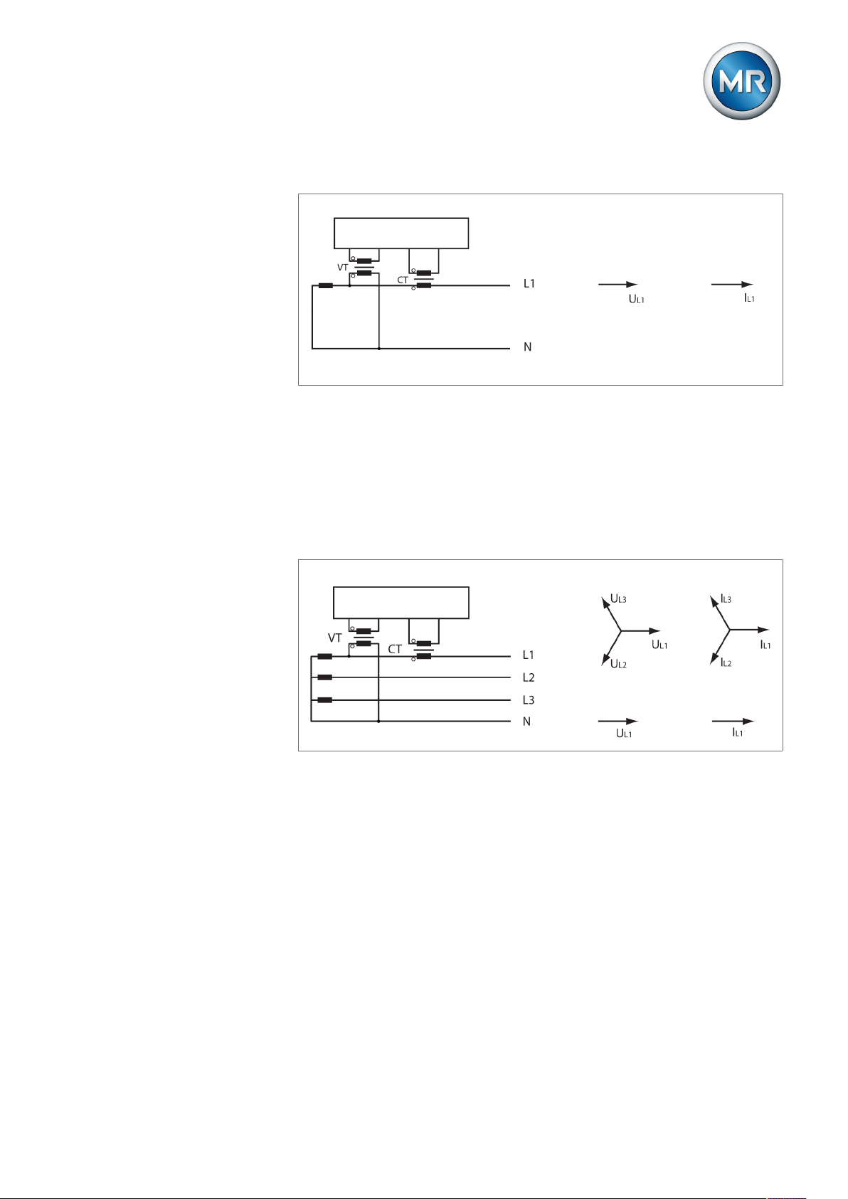
8 Operation
TAPCON® 230
TAPCON® 230
Circuit A: 1-phase measurement in 1-phase grid
Figure52: Phase difference 0 1PH
▪ The voltage transformer VT is connected to the outer conductor and neu-
tral conductor.
▪ The current transformer CT is looped into the outer conductor.
▪ The voltage UL1 and current IL1 are in phase.
▪ The voltage drop on an outer conductor is determined by the current IL1.
Circuit B: 1-phase measurement in 3-phase grid
Figure53: Phase difference 0 3PHN
▪ The voltage transformer VT is connected to the outer conductors L1 and
neutral.
▪ The current transformer CT is looped into the outer conductor L1.
▪ The voltage U and current I are in phase.
▪ The voltage drop on an outer conductor is determined by the current IL1.
Maschinenfabrik Reinhausen GmbH 2019 852117246/05 EN TAPCON®230 basic
Page 86
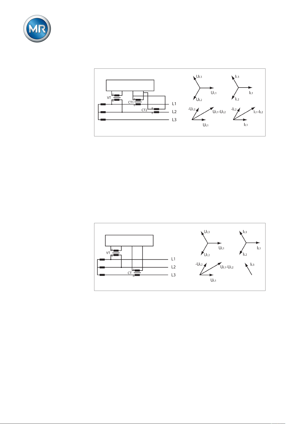
8 Operation
TAPCON® 230
TAPCON® 230
Circuit C:
Figure54: Phase difference 0 3PH
▪ The voltage transformer VT is connected to the outer conductors L1 and
L2.
▪ The current transformer CT1 is looped into the outer conductor L1 and
CT2 into the outer conductor L2.
▪ The current transformers CT1 and CT2 are connected crosswise in paral-
lel (total current = IL1+IL2).
▪ The total current IL1+IL2 and voltage UL1-UL2 are in phase.
▪ The voltage drop on an outer conductor is determined by the current:
(IL1+IL2)/√3.
Circuit D
Figure55: Phase difference 90 3PH
▪ The voltage transformer VT is connected to the outer conductors L1 and
L2.
▪ The current transformer CT is looped into the outer conductor L3.
▪ The current IL3 is ahead of voltage UL1-UL2 by 90°.
▪ The voltage drop on an outer conductor is determined by the current IL3.
Maschinenfabrik Reinhausen GmbH 201986 2117246/05 ENTAPCON®230 basic
Page 87

8 Operation
TAPCON® 230
TAPCON® 230
Circuit E
Figure56: Phase difference 30 3PH
▪ The voltage transformer VT is connected to the outer conductors L1 and
L2.
▪ The current transformer CT is looped into the outer conductor L2.
▪ The current IL2 is ahead of voltage UL2-UL1 by 30°.
▪ The voltage drop on an outer conductor is determined by the current IL2.
Circuit F
Figure57: Phase difference -30 3PH
▪ The voltage transformer VT is connected to the outer conductors L1 and
L2.
▪ The current transformer CT is looped into the outer conductor L1.
▪ The current IL1 lags behind UL1-UL2 by 30°. This corresponds to a phase
shift of -30°.
▪ The voltage drop on an outer conductor is determined by the current IL1.
Maschinenfabrik Reinhausen GmbH 2019 872117246/05 EN TAPCON®230 basic
Page 88

To set the phase difference for the transformer circuit, proceed as follows:
1. > Configuration > Transformer data > Press until the
desired parameter is displayed.
ð Transformer circuit.
2. Press or to select the required phase difference.
3. Press .
ð The phase difference is set.
8.8 Configurable inputs and outputs
You can individually configure the digital inputs (GPI ) and outputs (GPO ).
The following digital inputs and outputs are available:
▪ 6 digital inputs (GPI1...6)
▪ 2 digital outputs (GPO1 and 2)
8 Operation
8.8.1 Linking inputs with functions
You can activate the inputs as follows :
▪ Statically using signal statuses
– The input signal must be continually present (status: high level).
▪ Dynamically using pulses
– A pulse (rising edge) is needed at the input. The input signal must
change its status from "Low" to "High". If you are using a pulsed input,
you can trigger the assigned function at the same time as the keys connected to the inputs also using the control system.
You can recognize pulsed inputs from the preceding "P:". The note "Warning: P = pulsed inputs" is displayed on the screen.
You can assign one of the following functions to each of the digital inputs
(GPI 1...6):
Function Description
Off No function selected
Remote/Loc. Define remote/local mode.
Blocking Block automatic regulation.
Quick Tap Activating quick reset (deactivating delay
Signal on: "Remote" operating mode active.
Signal off: "Local" operating mode active.
time T1/T2)
Maschinenfabrik Reinhausen GmbH 201988 2117246/05 ENTAPCON®230 basic
Page 89
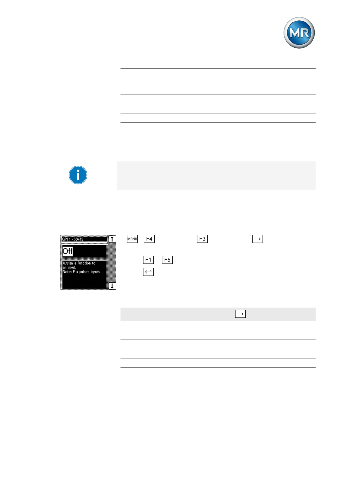
8 Operation
MPS tripped
MD in progr.
DVL 2
DVL 3 Activate desired value level 3
Blk U raise Block tap-change operations (raise).
Blk U low. Block tap-change operations (lower).
P: DV 1 Activate desired value 1
P: DV 2
P: DV 3
Table17: Functions for digital inputs (GPI 1...6)
Input for MPS tripped feedback.
Input for MD in progr. feedback.
Activate desired value level 2
Activate desired value 2
Activate desired value 3
If you assign the same functionality to two inputs, the device produces an
event message. This also applies if you assign the same functionality via a
static input and via a pulsed input.
Other examples of double assignment of functions are (n, m = 1...6):
▪ GPI n = master/follower and GPI m = P: DV 1
▪ GPI n = master/follower and GPI m = P: DV 2
To assign a function to a digital input or to deactivate it, proceed as follows:
1. > Configuration > User I/Os (press for further GPIs).
ð GPI
2. Press or until the desired function is displayed.
3. Press .
ð The function is set.
Functions can be assigned to all other GPIs as described above. You can
select the GPIs as follows:
GPI
GPI1–X4:13 GPI2–X4:14 1x
GPI3–X4:15 2x
GPI4–X4:16 3x
GPI5–X4:17 4x
GPI6–X4:18 5x
Table18: Configurable GPIs
Press
Maschinenfabrik Reinhausen GmbH 2019 892117246/05 EN TAPCON®230 basic
Page 90

8.8.2 Linking outputs with functions
You can assign one of the following functions to the digital outputs (GPO 1
and 2):
Function Description
Off No function selected
Local/Rem. Message: Local control/remote control
Undervoltage Message: Undervoltage blocking
Overvoltage Message: Overvoltage blocking
Undercurrent Message: Undercurrent blocking
Overcurrent Message: Overcurrent blocking
Desired value 1 Message: Desired value 1
Desired value 2 Message: Desired value 2
Desired value 3 Message: Desired value 3
MPS triggered Message: Motor protective switch was
Motor runtime > Message: Motor runtime exceeded.
Motor running Message: "Motor running"
Bandwidth < Message: Value fallen below bandwidth
Bandwidth > Message: Bandwidth exceeded
GPI 1 Message: GPI 1 active
GPI 2 Message: GPI 2 active
GPI 3 Message: GPI 3 active
GPI 4 Message: GPI 4 active
GPI 5 Message: GPI 5 active
GPI 6 Message: GPI 6 active
Table19: Functions for digital outputs (GPOs 1 and 2)
8 Operation
tripped.
To assign a function to a digital output or to deactivate it, proceed as follows:
1. > Configuration > User I/Os > Press until the desired
parameter is displayed.
ð GPO.
2. Press or until the desired function is displayed.
3. Press .
ð The function is set.
Functions can be assigned to all other GPOs as described above. You can
select the GPOs as follows:
Maschinenfabrik Reinhausen GmbH 201990 2117246/05 ENTAPCON®230 basic
Page 91
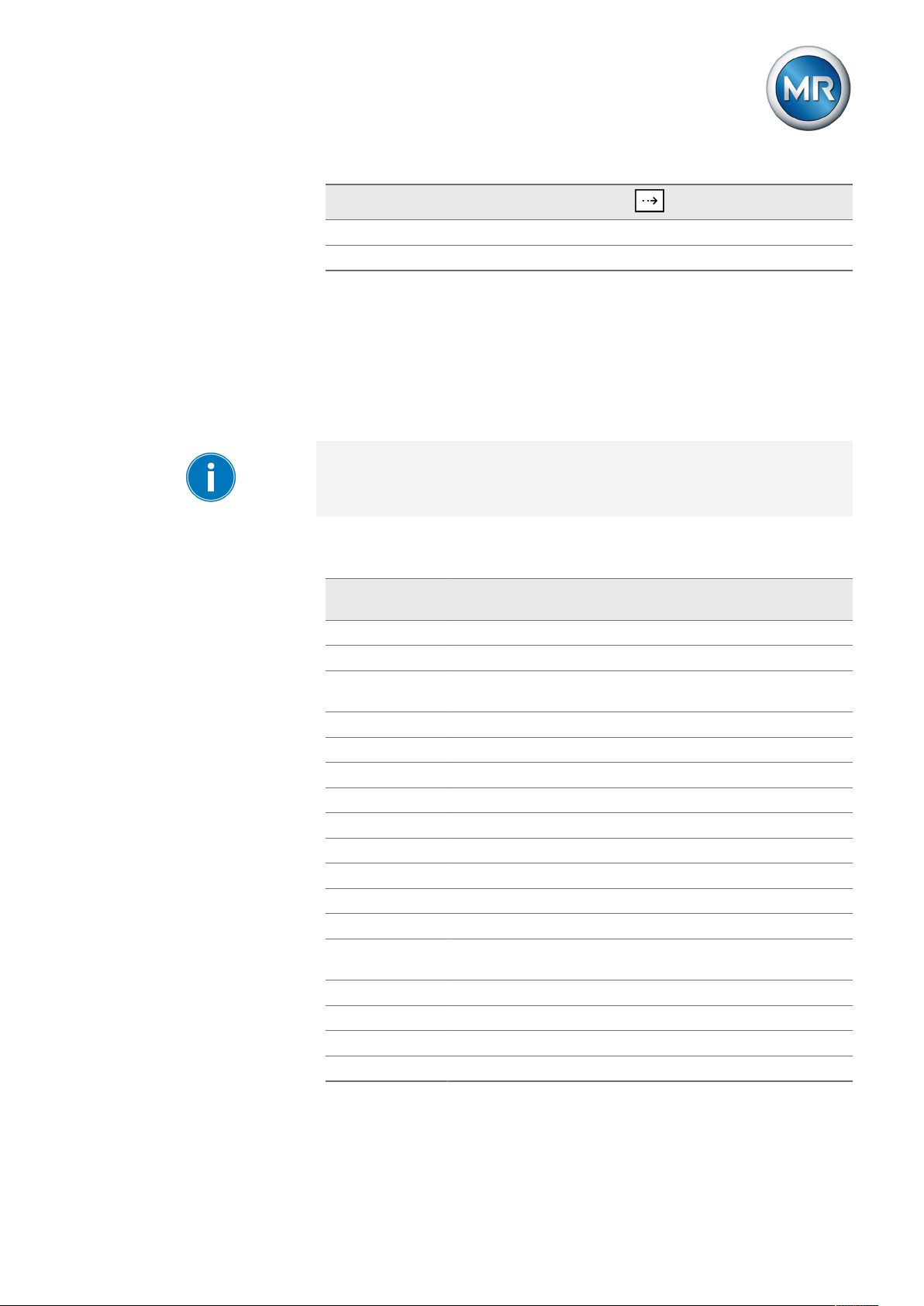
8 Operation
8.9 LED selection
Functions available for
LEDs
GPO
GPO1–X4:9 8x
GPO2–X4:12 9x
Table20: Configurable GPOs
Press
You can use this parameter to assign functions to the free LEDs which light
up when an event occurs. You can use labeling strips to label the LED.
Depending on your device configuration, the following parameters can be
used by MR for special functions. In this case, these parameters are pre-assigned. You may not be able to view or freely assign these parameters.
An overview of all possible functions which you can assign to the LEDs is
provided in the table below.
Functions available
Off LED deactivated
GPIx There is a signal at control input GPIx (e.g. GPI1)
GPOx The signaling relay at the GPOx (e.g. GPO 1) output has acti-
Undercurrent Undercurrent present
MPS triggered Motor protective switch triggered
Blocking Regulation is blocked
Automatic Auto mode active
Bandwidth< Value is below bandwidth
Bandwidth> Value is below bandwidth
Desired value1 Desired value1 activated
Desired value2 Desired value2 activated
Desired value3 Desired value3 activated
Function monitor-
ing
Remote Remote mode activated
Local Local mode activated
Auto Auto mode activated
Manual Manual mode activated
Table21: Functions available for LEDs
Function description
vated
Function monitoring message active
Maschinenfabrik Reinhausen GmbH 2019 912117246/05 EN TAPCON®230 basic
Page 92

8 Operation
Assigning function
To assign a function to an LED, proceed as follows:
1. > Configuration > LED selection > Press until the desired parameter is displayed.
2. Press or to select the option you want.
3. Press .
ð The function is assigned.
All additional LEDs can be assigned as described previously. The LEDs
available can be called up as follows:
LED (parameter) Characteristics
LED1 Single-colored LED2 Single-colored 1x
LED3 yellow Two-colored 2x
LED3 green Two-colored 3x
LED4 rot Two-colored 4x
LED4 yellow Two-colored 5x
Table22: Configurable LEDs
Press
Maschinenfabrik Reinhausen GmbH 201992 2117246/05 ENTAPCON®230 basic
Page 93

8 Operation
8.10 Information about device
8.10.1 Displaying info screen
The info screen displays the following information:
Figure58: Info screen
1 Type designation 4 Additional cards
2 Software version 5 RAM memory
3 Serial number
To display the info screen, proceed as follows:
► > Info.
ð Info.
8.10.2 Displaying measured values
The current measured values are shown in this display. The values on the
right in rows , and are only displayed if the transformer data [►Section 8.7, Page 81] has been entered previously. In row , the value actually
measured can be seen on the left and the value converted to the transformer
circuit is on the right.
Maschinenfabrik Reinhausen GmbH 2019 932117246/05 EN TAPCON®230 basic
Page 94

8 Operation
The following measured values can be displayed:
Figure59: Measured values
1 Voltage U in V or kV 3 Frequency f in Hz
2 Current I in % or A 4 Measurement performance PMeas
in % or MW
To display the measured values, proceed as follows:
► > Info > Press until the desired display appears.
ð Measured values.
8.10.3 Display calculated values
Calculated values are shown on this screen . The following values can be
displayed:
Figure60: Calculated values
1 I active (active share) in A 4 Reactive power Q in Mvar
2 I reactive (reactive share) in A 5 Power factor cos ϕ
3 Apparent power S in MVA 6 Operation counter
The values in the rows on the right are only displayed if the transformer data
has been entered previously.
Maschinenfabrik Reinhausen GmbH 201994 2117246/05 ENTAPCON®230 basic
Page 95

8 Operation
To display the calculated values, proceed as follows:
► > Info > Press until the desired display appears.
ð Calculated values
8.10.4 Carrying out LED test
You can check whether the LEDs are functioning properly. To do this, press
the relevant function key to illuminate an LED:
Key LED no.
...
+ ... +
Table23: Arrangement of keys for the LED test
LED1...LED5
LED6...LED9
All LEDs
This function will only test the functional reliability of the respective LED.
The function of the device linked to the LED is not tested.
To carry out the LED test, proceed as follows:
1. > Info > Press until the desired display appears.
ð LED test.
2. To carry out the function test, press the function key for the LED you want
to test.
8.10.5 Displaying status of the MIO card
The status of the digital inputs and outputs are shown in this display.
Maschinenfabrik Reinhausen GmbH 2019 952117246/05 EN TAPCON®230 basic
Page 96

8 Operation
Digital inputs
The status of the optocoupler inputs is shown in the "MIO card digital inputs"
display. As soon as a continuous signal is present at the input, status 1 is
displayed. 0 indicates no signal at the input.
Proceed as follows to display the status:
► > Info > Press until the desired display appears.
ð MIO card digital inputs
Digital outputs
The status of the relays is shown in the "MIO card digital outputs" display As
soon as a relay has activated, status 1 is displayed. If status 0 is displayed,
the relay has not activated.
Proceed as follows to display the status:
► > Info > Press until the desired display appears.
ð MIO card digital outputs
8.10.6 Resetting parameters
With this display you can reset your settings to the factory settings . It also
shows whether all parameters are saved correctly.
Resetting the parameters to the factory settings permanently deletes your
settings.
To reset all parameters, proceed as follows:
1. > Info > Press until the desired display appears.
ð Default parameter
2. Press and at the same time.
ð "Default parameter active" is displayed.
ð All parameters have been reset to the factory settings.
Maschinenfabrik Reinhausen GmbH 201996 2117246/05 ENTAPCON®230 basic
Page 97

8 Operation
8.10.7 Displaying memory overview
The memory overview can be used to display various database entries with
the relevant number of data records. The information is not relevant for operation. It is only needed for service checks. The following information is displayed:
▪ Parameter file
▪ Event data bits
▪ Flash file
▪ Events
To display the database entries, proceed as follows:
1. > Info > Press until the desired display appears.
ð Memory overview
2. Press or to select an entry.
ð The relevant number of data records is displayed.
8.10.8 Displaying event overview
This display can be used to display the number of current red and yellow
events. The events are marked as follows:
Yellow Corresponds to an advance warning or status information.
Red Automatic regulation can block.
Table24: Coding of events
A list with all events can be found in the Messages section.
To view the event overview, proceed as follows:
► > Info > Press until the desired display appears.
ð Event overview.
Maschinenfabrik Reinhausen GmbH 2019 972117246/05 EN TAPCON®230 basic
Page 98

9 Fault elimination
9 Fault elimination
This chapter describes how to rectify simple operating faults.
9.1 No regulation in AUTO mode
Characteristics/detail Cause Remedy
Device control commands have
no effect.
RAISE/LOWER LEDs light up periodically
Blocking Reverse power lock active. Check parameters.
Blocking
U< LED illuminated
Blocking
U> LED illuminated
Blocking
I> LED illuminated
Bandwidth set too high - Determine the recommended bandwidth
Table25: No regulation in AUTO mode
LOCAL/REMOTE switch in motordrive unit switched to LOCAL.
No connection Check wiring as per connection diagram.
Negative power flow Check current transformer polarity.
Function assigned to several
GPIs.
One of the GPIs is parameterized
with "Blocking" and has an appropriate input signal.
NORMset active Carry out manual tap-change operation with
Undercurrent blocking active Check parameters.
Undervoltage blocking active Check parameters.
Overvoltage blocking active Check parameters.
Overcurrent blocking active Check parameters.
Check operating mode. Correct if necessary.
Correct if necessary.
Check parameterization of GPIs.
Correct if necessary.
Check parameterization and status in "Info"
menu.
Correct if necessary.
or keys.
Correct if necessary.
Correct if necessary.
Correct if necessary.
Correct if necessary.
9.2 Unexplained tap change
Characteristics/detail Cause Remedy
Compensation activated Setting:
▪ Line drop compensation
▪ Z compensation
Table26: Unexplained tap change
Check parameters.
Correct if necessary.
Maschinenfabrik Reinhausen GmbH 201998 2117246/05 ENTAPCON®230 basic
Page 99

9 Fault elimination
9.3 Man-machine interface
Characteristics/detail Cause Remedy
Keys
▪ MANUAL/AUTO operating
mode cannot be changed
Keys
▪ LEDs in keys and
not illuminated.
Display
▪ No display.
LEDs
▪ Freely configurable LED lights
up
LEDs
▪ LED flashing
COM1
▪ Cannot be connected to PC
using TAPCON®-trol.
Table27: Man-machine interface
REMOTE operating mode active
and LED in key illuminated.
Parameter error Reset parameters to factory settings.
Contrast incorrectly set. Set contrast [►Section 7.1, Page 42].
Voltage supply interrupted. Check voltage supply.
Fuse faulty. Contact Maschinenfabrik Reinhausen.
Customized LED parameteriza-
tion.
Input signal not constant. Check input signal.
Different baud rates set. Check baud rate set on device and PC.
Press to activate LOCAL mode.
Check parameters.
9.4 Incorrect measured values
Characteristics/detail Cause Remedy
Measured voltage
▪ No measured value.
Measured voltage
▪ Measured value too low.
Measured voltage
▪ Measured value fluctuates.
Measured current
▪ No measured value.
Connection has no contact in the
plug terminal.
Insulation trapped
Wire not inserted far enough.
Circuit breaker tripped. Check fuse.
Voltage drop on measuring lead. Check measured voltage at plug terminal X2:1/
Possible sources of fault:
▪ Leads laid in parallel.
▪ Tap-change operations.
Line to current transformer interrupted.
Short-circuiting jumper in current
transformer not removed.
Check wiring and plug terminal.
X2:2.
Check measured voltage at plug terminal X2:1/
X2:2.
Increase distance from source of interference.
Install filter if necessary.
Check wiring.
Remove short-circuiting jumper.
Maschinenfabrik Reinhausen GmbH 2019 992117246/05 EN TAPCON®230 basic
Page 100

Characteristics/detail Cause Remedy
Measured current
▪ Measured value too high.
▪ Measured value too low.
Phase angle
▪ U/I.
Table28: Incorrect measured values
Transmission ratio not correctly
parameterized.
Incorrect input connected. Remove short-circuiting jumper.
Fault in external transformer circuit.
Transformer circuit incorrectly parameterized.
Correct parameterization.
Check transformer circuit.
Compare with system connection diagram.
Correct parameters.
Compare measurement values on info screen.
Transpose current transformer connection.
Check polarity of transformer circuit.
Correct if necessary.
Check circuit.
Correct if necessary.
Check measurement points.
Correct if necessary.
9 Fault elimination
9.5 Customized GPIs/GPOs
Characteristics/detail Cause Remedy
Function expected from the factory setting does not take place
Signal discontinuous. Intermittent DC voltage. Check source of DC voltage.
No signal
Info screens "Bandwidth!, "Delay
time T1", "Control response T1",
"Delay time T2" display 0.
Table29: Fault elimination: GPIs and GPOs
Parameterization has been overwritten manually or via
TAPCON®-trol.
Supply voltage too low Reset parameters to factory settings.
Check active parameters
Check signal transmitter.
Check wiring.
9.6 General faults
Characteristics/detail Cause Remedy
No function
▪ Operating status LED does
not illuminate
No power supply Check the power supply
Fuse tripped Contact Maschinenfabrik Reinhausen GmbH
Maschinenfabrik Reinhausen GmbH 2019100 2117246/05 ENTAPCON®230 basic
 Loading...