

Page 1
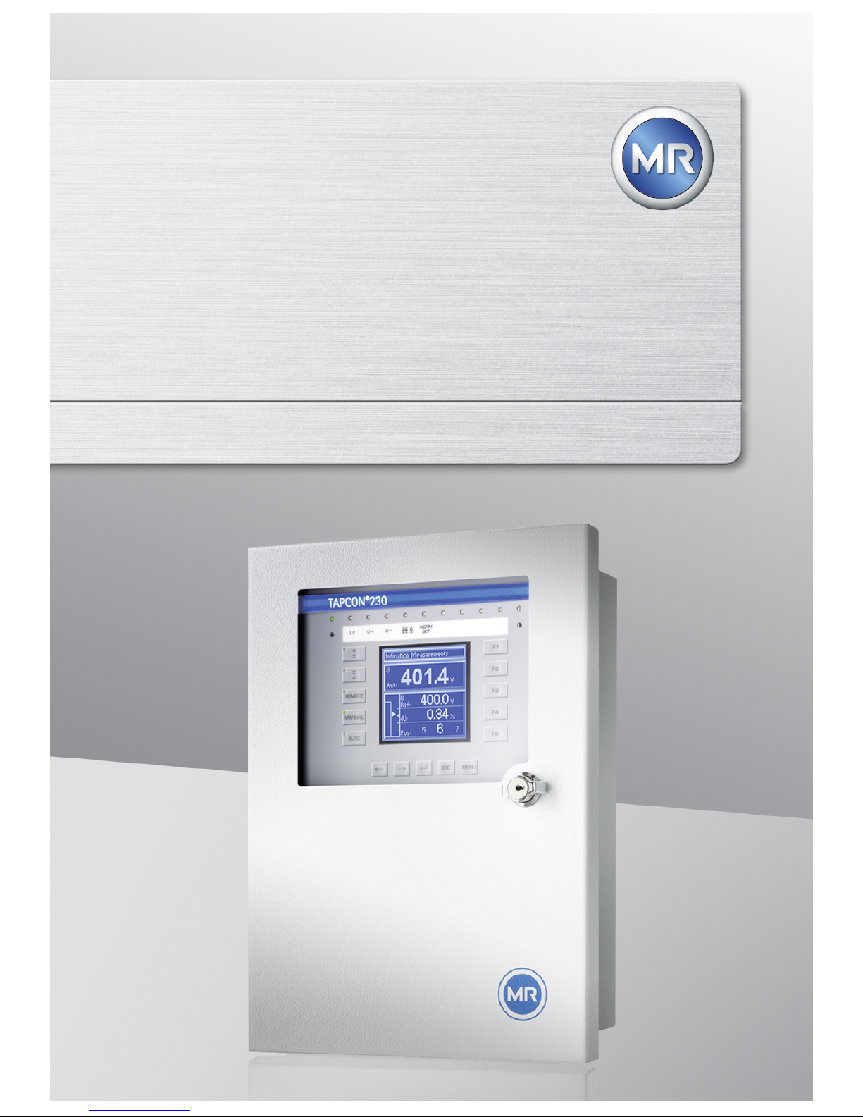
Voltage Regulator
TAPCON® 230
Quick Guide
4831166/00
Page 2

© All rights reserved by Maschinenfabrik Reinhausen
Dissemination and reproduction of this document and use and disclosure of its content are
strictly prohibited unless expressly permitted.
Infringements will result in liability for compensation. All rights reserved in the event of the
granting of patents, utility models or designs.
The product may have been altered since this document was published.
We reserve the right to change the technical data, design and scope of supply.
Generally the information provided and agreements made when processing the individual
quotations and orders are binding.
The original operating instructions were written in German.
Page 3

Table of contents
3
Table of contents
1 Introduction.............................................................................. 5
1.1 Manufacturer............................................................................. 5
1.2 Completeness............................................................................ 5
1.3 Supporting documents............................................................... 5
1.4 Safekeeping............................................................................... 6
2 Safety........................................................................................ 7
3 Hardware.................................................................................. 8
3.1 Operating controls..................................................................... 8
3.2 Display elements..................................................................... 10
4 Functions and settings......................................................... 13
4.1 Setting the language................................................................ 13
4.2 NORMset................................................................................. 14
4.3 Control parameters.................................................................. 17
4.3.1 Setting desired value 1...3..................................................................... 17
4.3.2 Selecting a desired value....................................................................... 18
4.3.3 Setting delay time T1............................................................................. 19
4.3.4 Setting control response T1................................................................... 20
4.3.5 Setting delay time T2............................................................................. 21
4.4 Information about device......................................................... 22
Page 4

Table of contents
4
5 Overview of parameters........................................................ 24
Page 5

1 Introduction
5
Introduction
This technical file contains information for quick start-up
of the product. It does not provide comprehensive operating instructions.
This technical file is intended solely for specially trained
and authorized personnel.
Manufacturer
The product is manufactured by:
Maschinenfabrik Reinhausen GmbH
Falkensteinstraße 8
93059 Regensburg, Germany
Tel.: (+49) 9 41/40 90-0
Fax: (+49) 9 41/40 90-7001
E-mail: [email protected]
Further information on the product and copies of this
technical file are available from this address if required.
Completeness
This technical file is incomplete without the supporting
documentation.
Supporting documents
The following documents apply to this product:
1
1.1
1.2
1.3
Page 6

1 Introduction
6
Also observe generally valid legislation, standards and
guidelines as well as specifications on accident prevention and environmental protection in the respective country of use.
Safekeeping
This technical file and all supporting documents must be
kept ready at hand and accessible for future use at all
times.
1.4
Page 7

2 Safety
7
Safety
This technical file does not replace the operating instructions for the voltage regulator. The quick reference guide
contains information that will provide a rapid introduction
to operating the voltage regulator.
▪ For detailed operation and safety information
please read carefully through the voltage regulator
operating instructions.
▪ Pay particular attention to the information in the
chapter on safety in the operating instructions.
2
Page 8

3 Hardware
8
Hardware
Operating controls
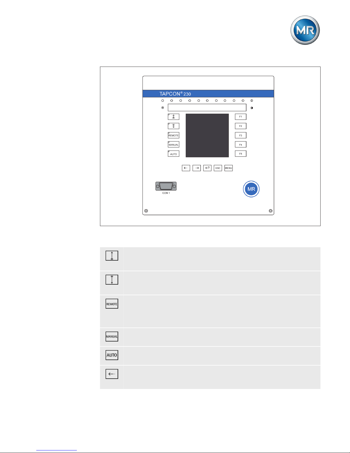
The device has 15 pushbuttons. The illustration below is
an overview of all the device's operating controls.
3
3.1
Page 9
3 Hardware
9
Figure 1: Operating controls
RAISE key: Sends control command for raise tapchange to the motor-drive unit in manual mode.
LOWER key: Sends control command for lower tapchange to the motor-drive unit in manual mode.
REMOTE key: Activate/deactivate "Remote" operating
mode. When you deactivate this operating mode, the
"Local" operating mode is automatically activated.
MANUAL key: Activate "Manual mode" operating mode.
AUTO key: Activate "Auto mode" operating mode.
PREV key: Change measured value display and switch
to previous parameters.
Page 10
3 Hardware
10
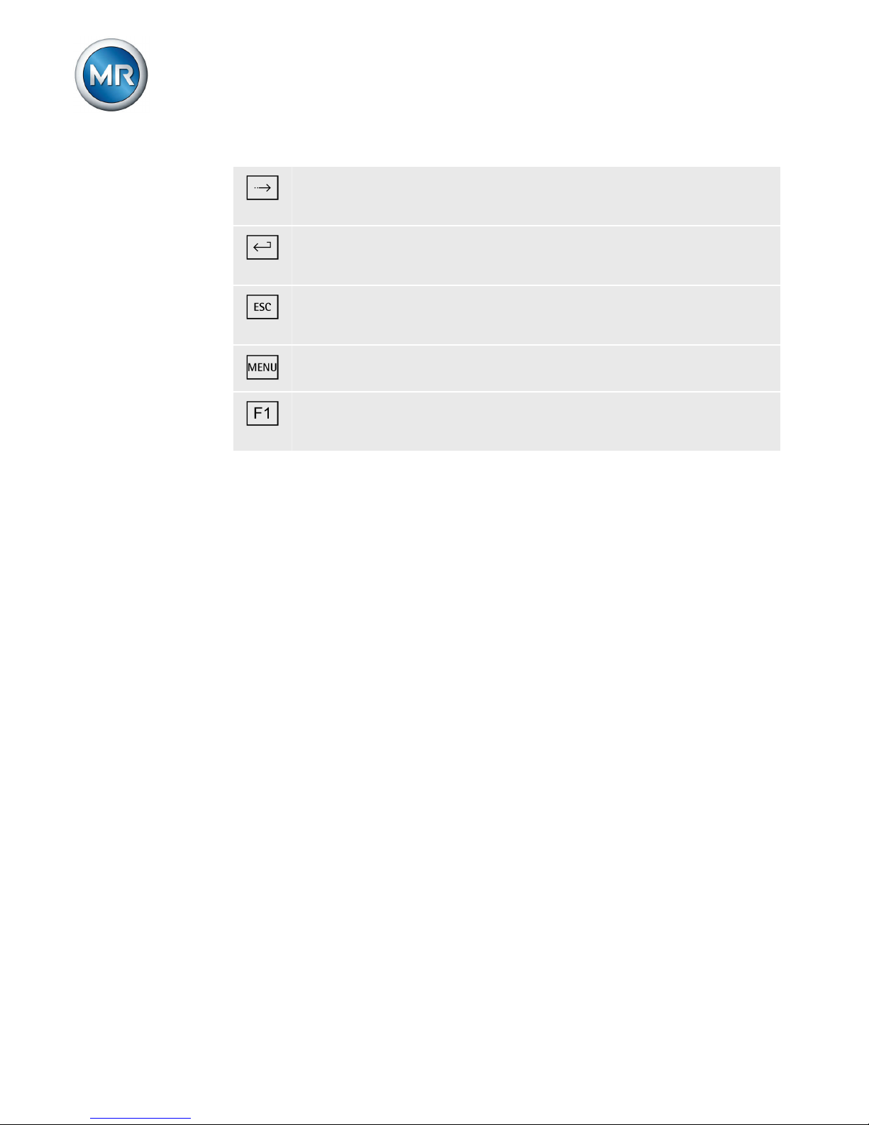
NEXT key: Change measured value display and switch
to next parameters.
ENTER key: Confirm selection and save modified parameters.
ESC key: Escape current menu and select previous
menu levels.
MENU key: Select main menu.
F1 to F5 function keys: Select functions displayed on the
screen.
Display elements
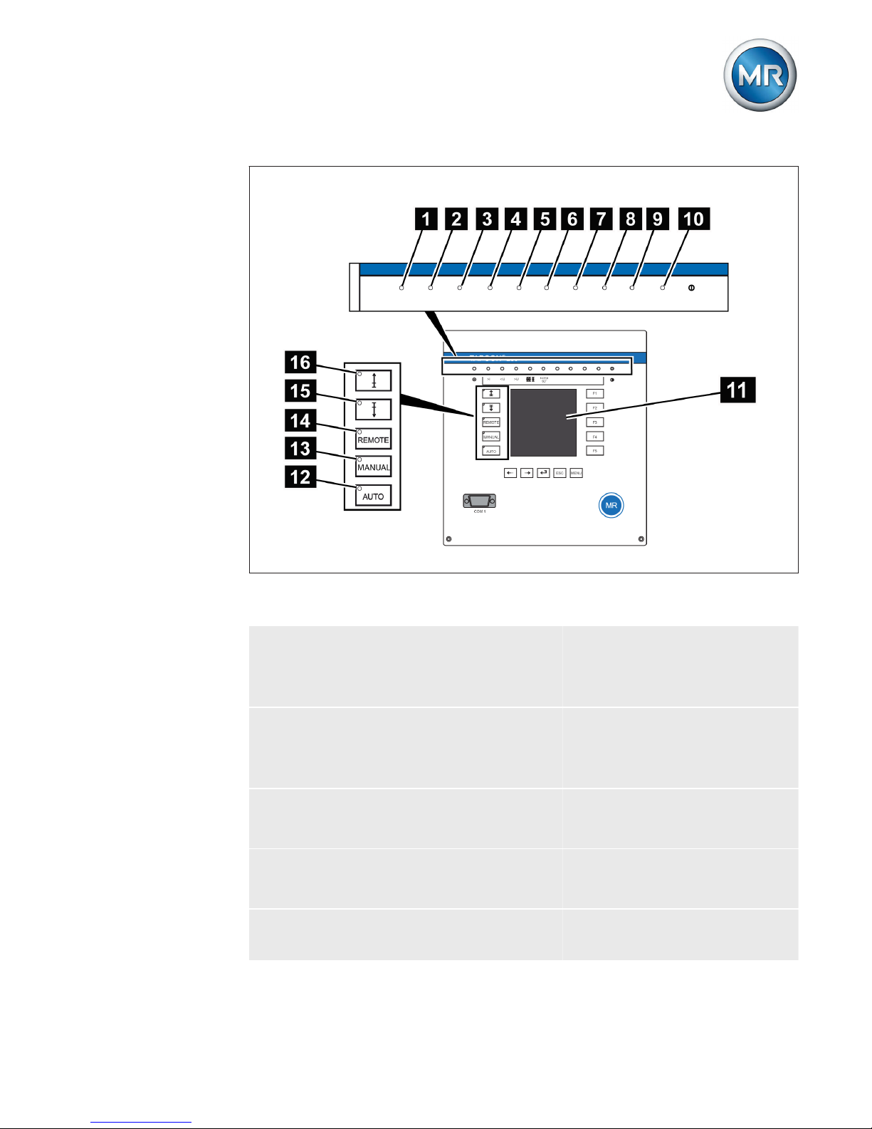
The device has a graphics display and 15 LEDs, which
indicate the various operating statuses or events.
3.2
Page 11
3 Hardware
11
Figure 2: Indicator elements
1 Operating status LED,
green
9 LED 3, function can be
freely assigned, yellow/
green
2 Overcurrent blocking
LED, red
10 LED 4, function can be
freely assigned,
yellow/red
3 Undervoltage blocking
LED, red
11 Graphics display
4 Overvoltage blocking
LED, red
12 Auto operating mode ac-
tive LED
5 Parallel operation active
LED, green
13 Manual operating mode
active LED
Page 12

3 Hardware
12
(only for TAPCON® 230
pro and TAPCON® 230
expert)
6 NORMset active LED,
green
14 Remote operating mode
active LED
7 LED 1, function can be
freely assigned, yellow
15 Lower tap-change active
LED
8 LED 2, function can be
freely assigned, yellow
16 Raise tap-change active
LED
Page 13
4 Functions and settings
13
Functions and settings
This chapter gives a short summary of all important functions and possible settings of the voltage regulator. For
details, see the voltage regulator's operating instructions.
Before carrying out the parameterization, proceed as follows:
1. If necessary, press and at the same time to
deactivate the key lock.
2. Press to select manual mode.
3. Press to select the main menu.
ð The parameters can be set.
Setting the language
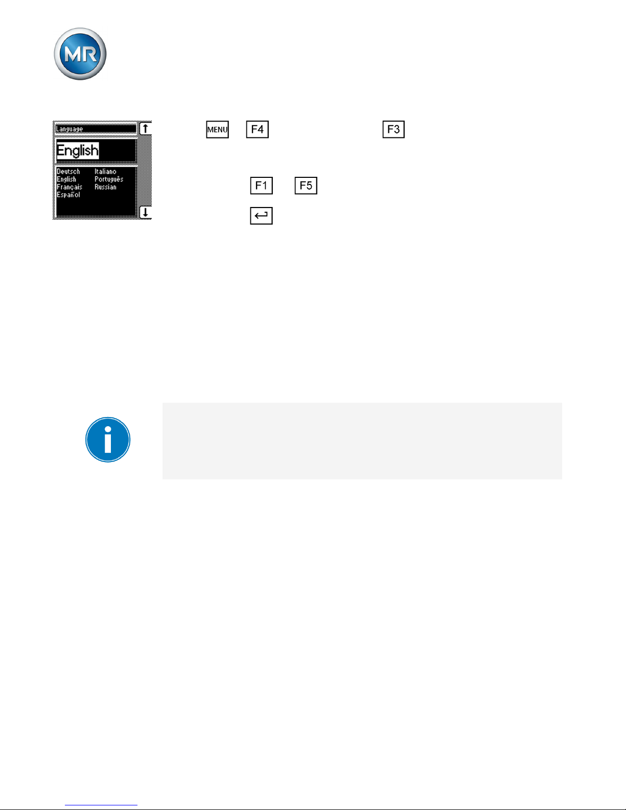
You can use this parameter to set the display language
for the device. The following languages are available:
English Italian
German Portuguese
French Russian
Spanish
To set the language, proceed as follows:
4
4.1
Page 14
4 Functions and settings
14
1. > Configuration > General.
ð Language
2. Press or to select the required language.
3. Press .
ð The language is set.
NORMset
NORMset mode is used for quickly starting voltage regulation. In NORMset mode, the bandwidth and delay time
parameters are automatically adapted to the requirements of the grid.
Line drop compensation cannot be performed in
NORMset mode.
Set the following parameters to operate the device in
NORMset mode.
Activating/deactivating NORMset
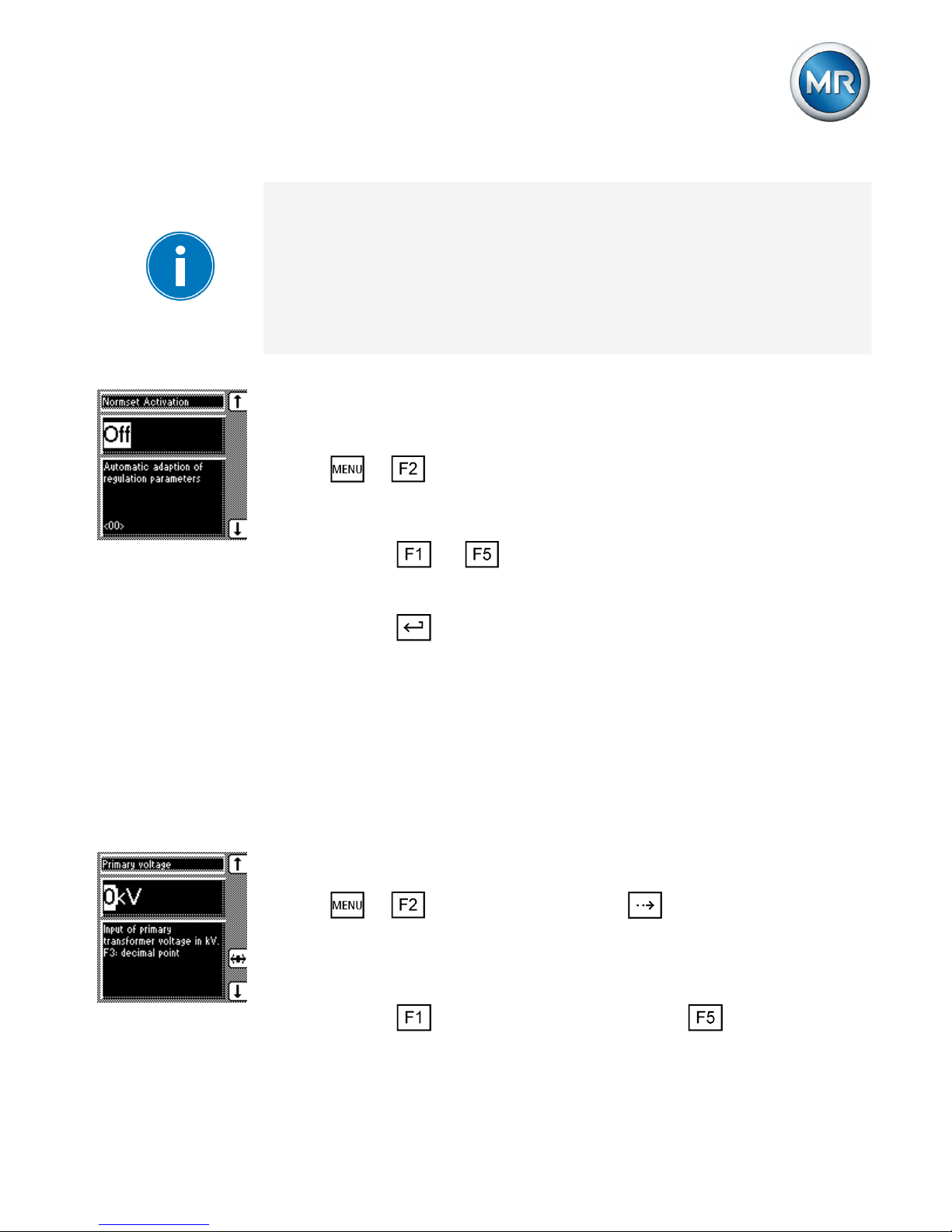
You can use this parameter to activate NORMset mode.
4.2
Page 15
4 Functions and settings
15
A manual tap-change operation is required to activate
NORMset. This is how the voltage regulator determines
the bandwidth required.
If the transformer is switched off, another manual tapchange operation is required.
Proceed as follows to activate/deactivate NORMset
mode:
1. > NORMset
ð NORMset activation.
2. Press or to activate NORMset by selecting
On or to deactivate NORMset by selecting Off.
3. Press .
ð NORMset is activated/deactivated.
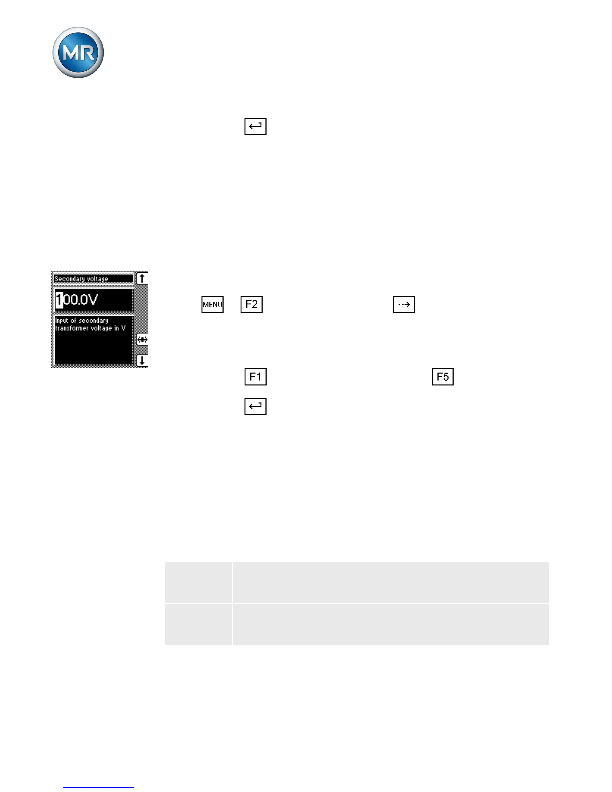
Setting the primary voltage
With this parameter, you can set the voltage transformer's primary voltage.
Proceed as follows to set the primary voltage:
1. > NORMset > Press until the desired
parameter is displayed.
ð Primary voltage.
2. Press to increase the value or to reduce it.
Page 16
4 Functions and settings
16
3. Press .
ð The primary voltage is set.
Setting the secondary voltage
With this parameter, you can set the voltage transformer's secondary voltage.
Proceed as follows to set the secondary voltage:
1. > NORMset > Press until the desired
parameter is displayed.
ð Secondary voltage.
2. Press to increase the value or to reduce it.
3. Press .
ð The secondary voltage is set.
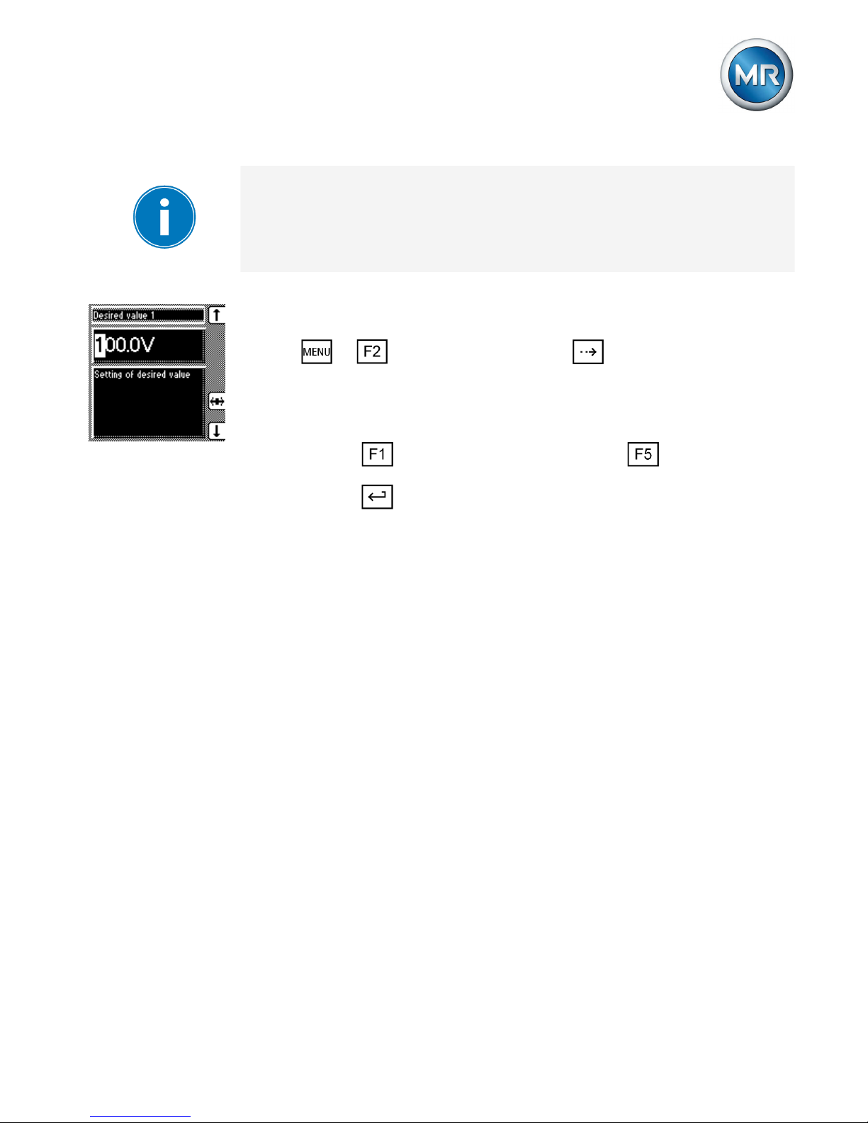
Setting desired value 1
With this parameter, you can set the desired value for automatic voltage regulation. You can enter the desired value as follows:
In V The value relates to the secondary voltage of the
voltage transformer.
In kV The value relates to the primary voltage of the volt-
age transformer.
Table 1: Desired value setting
Page 17
4 Functions and settings
17
Settings in kV are only possible if you have previously
entered the parameters for primary and secondary voltage.
Proceed as follows to set the desired value:
1. > NORMset > Press until the desired
parameter is displayed.
ð Desired value 1.
2. Press to increase the value or to reduce it.
3. Press .
ð The desired value is set.
Control parameters
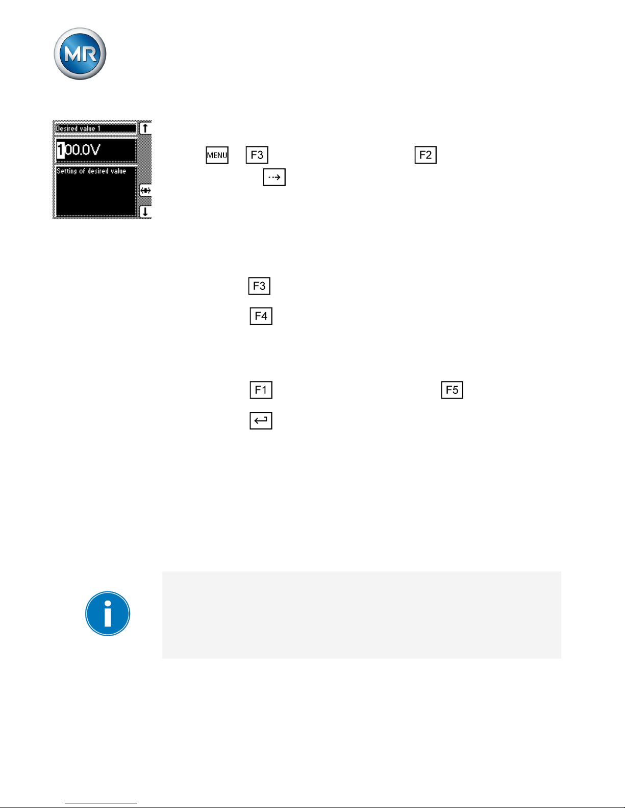
Setting desired value 1...3
You can set up to 3 desired voltage values. Desired value 1 is the default desired value. Desired values 2 and 3
are activated if there is a continuous signal at factory-preset control inputs 4:17 or X4:18.
4.3
4.3.1
Page 18
4 Functions and settings
18
Proceed as follows to set the desired value:
1. > Control parameter > voltage regulator
> Press until the desired parameter is dis-
played.
ð Desired value 1/Desired value 2/Desired val-
ue 3.
2. If you have already entered the transformer data,
press to select the unit you want: "V" or "kV".
3. Press to highlight the position.
ð The desired position is highlighted and the
value can be changed.
4. Press to increase the value or to reduce it.
5. Press .
ð The desired value is set.
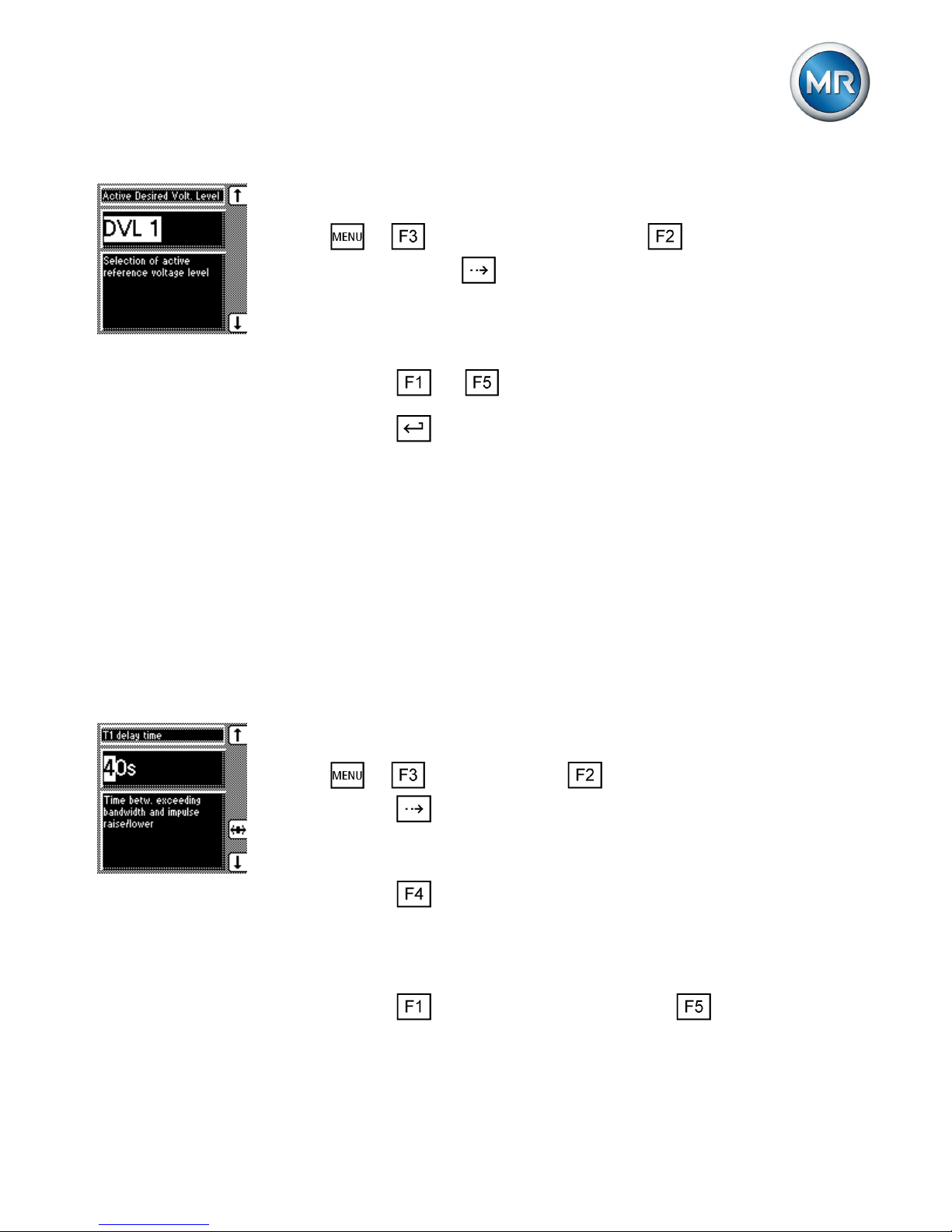
Selecting a desired value
You can use this parameter to select the active desired
value 1, 2 or 3.
If you select the desired value using appropriately configured GPIs, this parameter's setting is ignored. Refer
to the operating instructions for more information about
GPI configuration.
4.3.2
Page 19
4 Functions and settings
19
Proceed as follows to select a desired value:
1. > Control parameter > Voltage regulation > Press until the desired parameter is dis-
played.
ð Active Desired Volt. Level
2. Press or to select an active desired value.
3. Press .
ð The selected desired value is active.
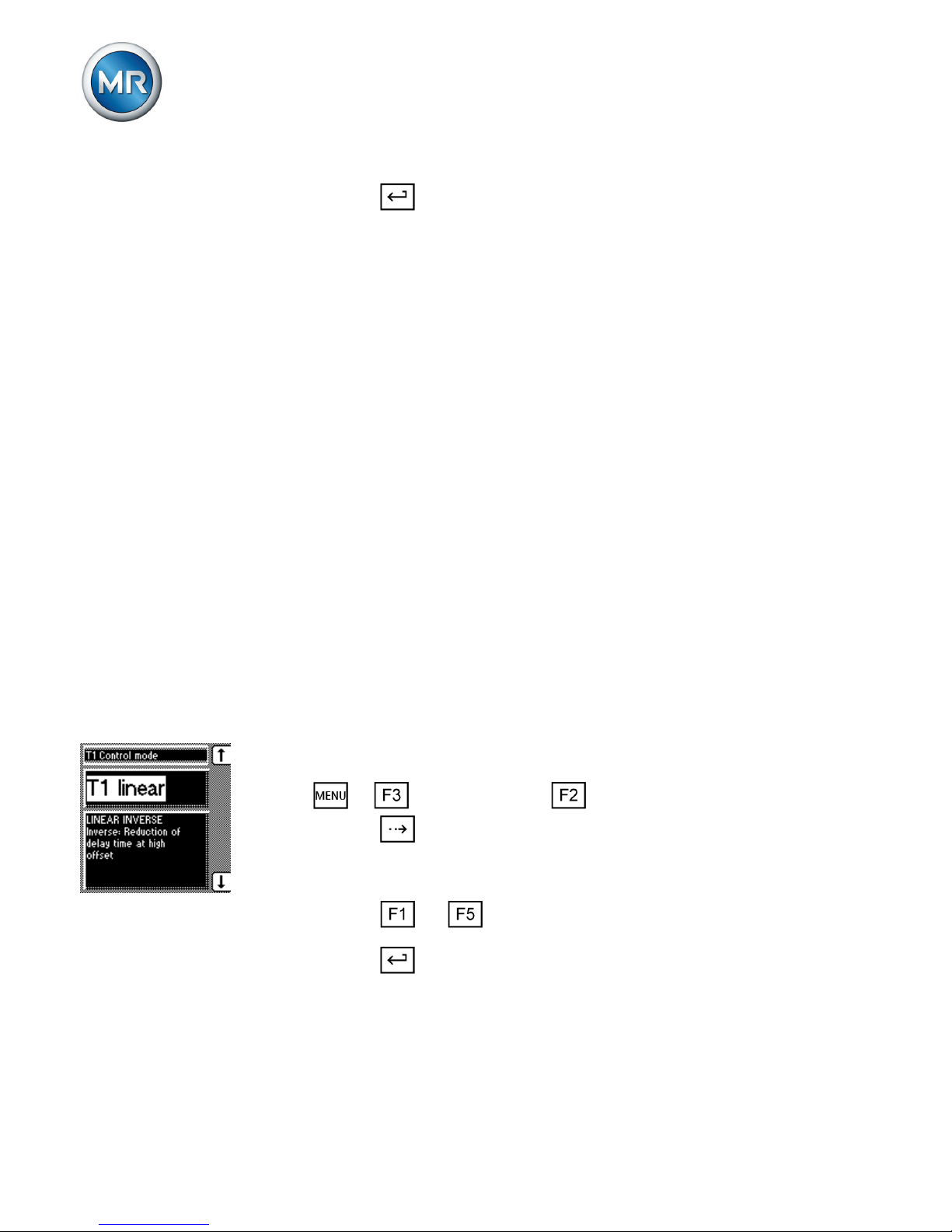
Setting delay time T1
This function delays the issuing of a tap-change command for a defined period. This prevents unnecessary
tap-change operations if the tolerance bandwidth is exited.
To set the delay time T1, proceed as follows:
1. > Parameter > Control parameter >
Press until the desired parameter is displayed.
ð Delay time T1.
2. Press to highlight the position.
ð The desired position is highlighted and the
value can be changed.
3. Press to increase the time or to reduce it.
4.3.3
Page 20
4 Functions and settings
20
4. Press .
ð The delay time T1 is set.
Setting control response T1
You can set the control response as linear or integral.
Linear
Device responds with a constant delay time which is independent of the control deviation.
Integral
Device responds with a variable delay time which is dependent on the control deviation. The greater the control
deviation (ΔU) in relation to the set bandwidth (B), the
shorter the delay time.
Proceed as follows to set the control response T1:
1. > Parameter > Control parameter >
Press until the desired parameter is displayed.
ð Control response T1.
2. Press or to set the response you want.
3. Press .
ð The control response T1 is set.
4.3.4
Page 21
4 Functions and settings
21
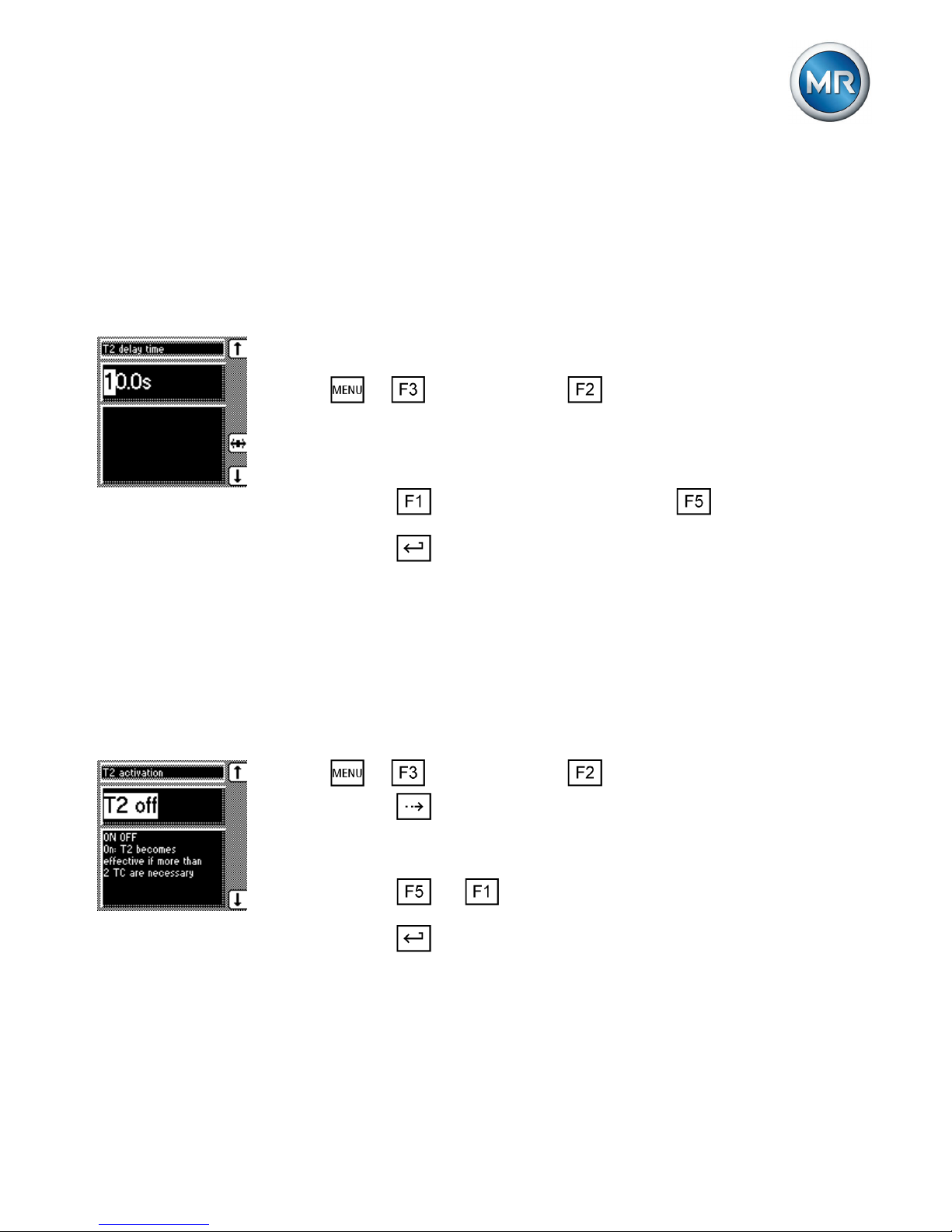
Setting delay time T2
With this parameter, you can set delay time T2. Delay
time T2 is used to compensate for large control deviations faster.
Proceed as follows to set the delay time T2:
1. > Parameter > Control parameter >
Press until the desired parameter is displayed.
ð Delay time T2.
2. Press to increase the time or to reduce it.
3. Press .
ð The delay time T2 is set.
Activating/deactivating delay time T2
To activate/deactivate the delay time T2, proceed as follows:
1. > Parameter > Control parameter >
Press until the desired parameter is displayed.
ð T2 activation.
2. Press or to activate/deactivate T2.
3. Press .
ð The delay time T2 is activated/deactivated.
4.3.5
Page 22

4 Functions and settings
22
Information about device
The info screen displays the following information:
To display the info screen, proceed as follows:
► > Info.
ð Info.
By pressing , the following information screens are also displayed:
▪ Measured values
▪ Calculated values
▪ Functional reliability of the LEDs (LED test)
▪ Default parameter
▪ Memory overview
▪ Event overview
▪ MIO card digital inputs
▪ MIO card digital outputs
▪ PIO card digital inputs
1
▪ PIO card digital outputs
1
▪ PIO card analog input
1
▪ Parallel operation
1
▪ Data on CAN bus
1
▪ Peak memory
1
▪ CI card information
2
4.4
Page 23

4 Functions and settings
23
▪ IEC 61850 card information
3
1
Only for TAPCON® 230 pro and TAPCON® 230 expert.
2
Only for TAPCON® 230 expert with CI card.
3
Only for TAPCON® 230 expert with IEC 61850 card.
Page 24
5 Overview of parameters
24
Overview of parameters
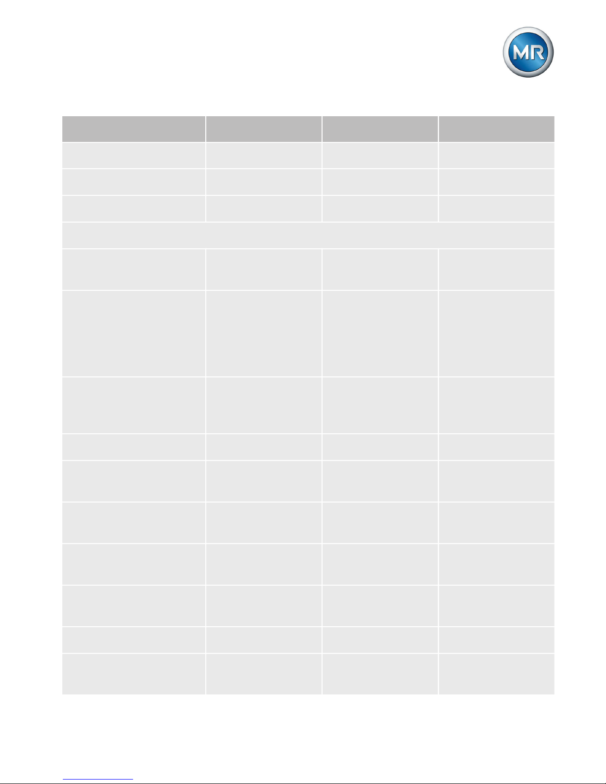
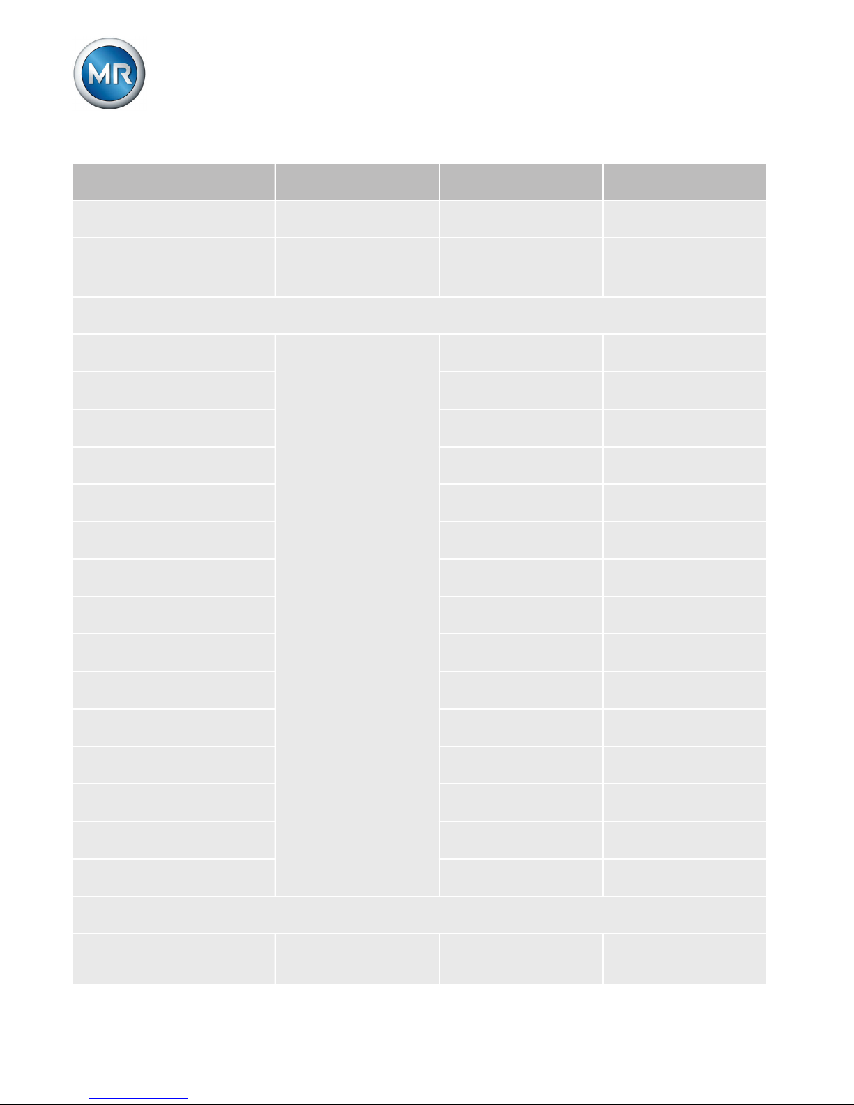
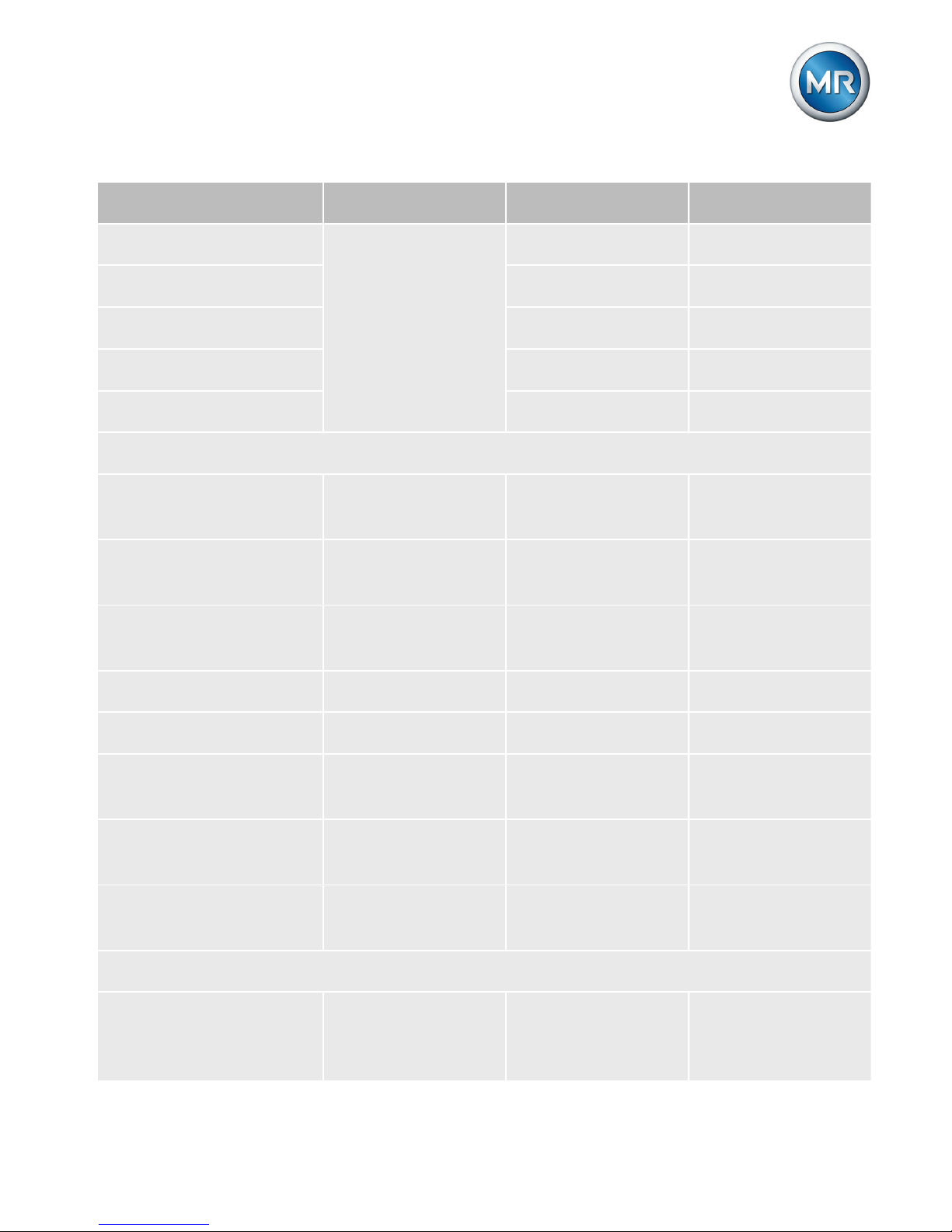
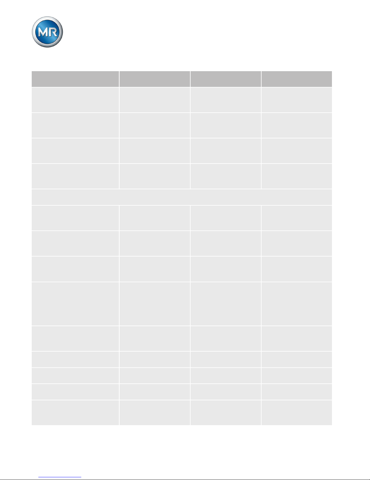
This section contains an overview of the relevant menus
and parameters. The availability of individual parameters
varies depending on the device ordered.
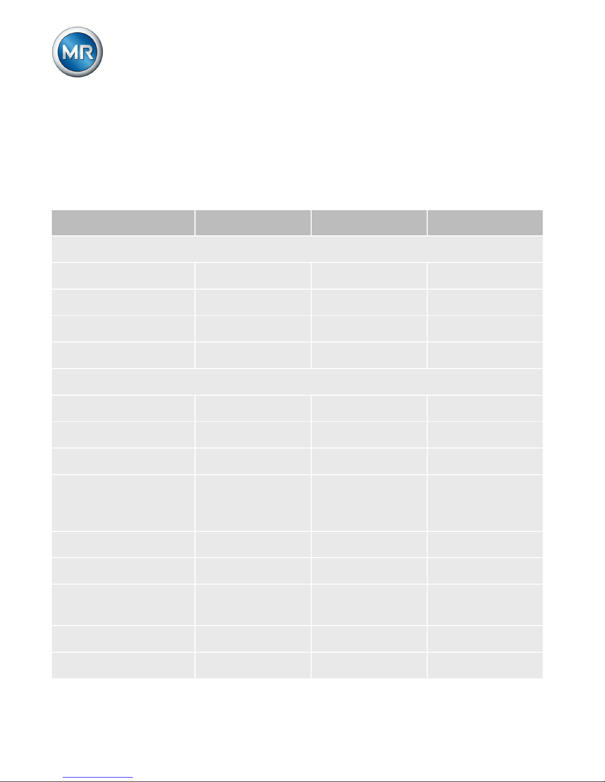
Parameter Setting range Factory setting Current setting
NORMset
Normset activation On, Off Off
Desired value 1 49...140 V 100 V
Primary voltage 0...9,999 kV 0 kV
Secondary voltage 57...123 V 100 V
Control parameters > Voltage regulation
Desired value 1 49...140 V 100.0 V
Desired value 2 49...140 V 100.0 V
Desired value 3 49...140 V 100.0 %
Desired value selection
Desired value 1;
Desired value 2;
Desired value 3
Desired value 1
Bandwidth 0.5...9 % 2.00 %
Delay time T1 0...600 s 40 s
Control response T1 T1 linear, T1 inte-
gral
T1 linear
Activation T2 T2 on, T2 off T2 off
Delay time T2 1...10 s 10.0 s
5
Page 25
5 Overview of parameters
25
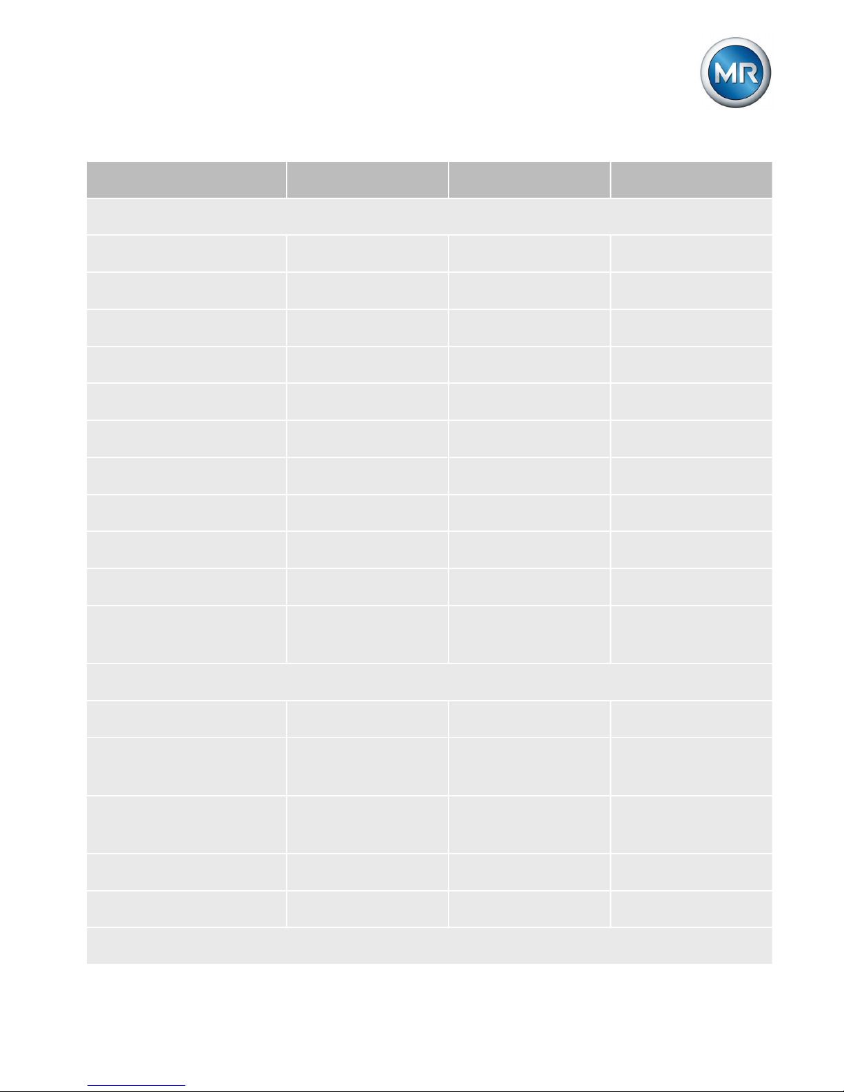
Parameter Setting range Factory setting Current setting
Control parameters > Limit values
Undervoltage U< [%] 60...100 % 90 %
Delay time U< 0...20 s 10.0 s
Undervolt. blocking U< On, Off On
U< below 30 V On, Off Off
Overvoltage U> [%] 100...140 % 110 %
Overvolt. blocking U> On, Off Off
Overcurrent I> [%] 50...210 % 110 %
Overcurr. blocking I>. On, Off On
Undercurrent I< [%] 0...210 % 0 %
Undercurr. blocking I< On, Off Off
Neg. active power
block.
On, Off Off
Control parameters > Compensation
Compensation method LDC; Z LDC
Line drop compensation Ur
-25...25 V 0.0 V
Line drop compensation Ux
-25...25 V 0.0 V
Z compensation 0...15 % 0.0 %
Z comp. limit value 0...15 % 0.0 %
Configuration > Transformer data
Page 26
5 Overview of parameters
26
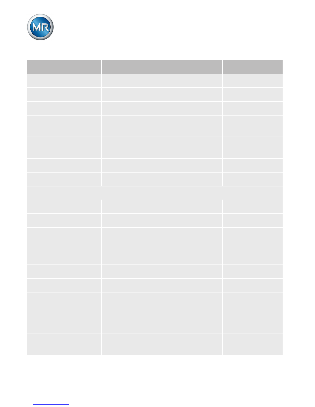
Parameter Setting range Factory setting Current setting
Primary voltage 0...9,999 kV 0 kV
Secondary voltage 57...123 V 100.0 V
Primary current 0...10,000 A 0 a
Current transformer
connection
Unknown; 1 A;
5 A
Unknown
Transformer circuit see operating in-
structions
0 1PH
Display kV / V kV, V V
Display % / A %, A %
Configuration > General
Language See [► 13] English
Regulator ID - 0000
Baud rate 9.6 kilobaud;
19.2 kilobaud;
38.4 kilobaud;
57.6 kilobaud
57.6 kilobaud
R/L pulse duration 0...10 s 1.5 s
Operations counter 0...99,999,999 0
Display dimming On, Off On
Key lock On, Off On
Function monitoring On, Off Off
Delay function monitoring
0...120 min 15 min
Page 27
5 Overview of parameters
27
Parameter Setting range Factory setting Current setting
Motor runtime 0...30 s 0.0 s
Manual/Automatic Manual, Auto Manual
Local/Remote Local, Remote Local
Configuration > Parallel operation
1)
Parallel operation activation
On, Off On
Parallel operation
method
Circulating reactive current; Master; Follower; Auto synchronization
Circulating reactive current
Parallel operation
group
None; Group 1;
Group 2; Group 1
and Group 2
None
CAN address 0...16 0
Simplex mode blocking.
On, Off On
Circulating reactive
current sensitivity
0...100 % 0.0 %
Circulating reactive
current blocking
0.5...40 % 20.0 %
Master/follower current blocking
Blocking, Off Blocking
Parallel error delay 1...999 s 10 s
Follower tapping direction
Standard, Swapped
Standard
Page 28
5 Overview of parameters
28
Parameter Setting range Factory setting Current setting
Max. tap difference 1...4 1
Follower tapping without U
meas
On, Off Off
Configuration > Customer inputs/outputs
GPI 1 – X4:13 see operating in-
structions
Off
GPI 2 – X4:14 Off
GPI 3 – X4:15 Off
GPI 4 – X4:16 Quick Tap
GPI 5 – X4:17 Desired value 2
GPI 6 – X4:18 Desired value 3
GPI 7 – X6:1
1)
ParGroup1
GPI 8 – X6:2
1)
ParGroup2
GPO 1 – X4:9 Off
GPO 2 – X4:12 Off
GPO 3 – X5:9
1)
ParState
GPO 4 – X5:12
1)
ParError
GPO 5 – X5:18
1)
Undervoltage
GPO 6 – X5:21
1)
Overvoltage
GPO 7 – X5:24
1)
Overcurrent
Configuration > LED selection
LED1 see operating in-
structions
GPI 1
Page 29
5 Overview of parameters
29
Parameter Setting range Factory setting Current setting
LED2 GPI 2
LED3 yellow Off
LED3 green Off
LED4 yellow Off
LED4 red Off
Configuration > Tap position
1)
Tap pos. capture see operating in-
structions
Off
Analog Val. [%] Tap
pos. min
0...100 % 0.0 %
Analog Val. [%] Tap
pos. max.
0...100 % 100.0 %
Lowest tap position -40...40 0
Highest tap position -40...40 19
Lower tap position
blocking
-128...128 0
Upper tap position
blocking
-128...128 40
Tap position limits
blocking behavior
Off; Directional;
Non-directional
Off
Configuration > Setting desired voltage level remotely
1)
Setting desired voltage level remotely
Off; 0/4..20 mA;
potentiometer
series
Off
Page 30
5 Overview of parameters
30
Parameter Setting range Factory setting Current setting
Analog value desired
value min
0...100 % 0.0 5
Analog value desired
value max
0...100 % 100.0 %
Minimum desired val-ue0...140 V 80.0 V
Maximum desired val-ue0...140 V 140.0 V
Configuration > Communication interface
2)
Communication protocol
see operating instructions
Modb. ASCII
Modbus format see operating in-
structions
8E1
Communication port RS232; RS485;
Ethernet; OF
RS232
Baud rate communication
9.6 kilobaud;
19.2 kilobaud;
38.4 kilobaud;
57.6 kilobaud
9.6 kilobaud
Network address 0.0.0.0...255.255.
255.255
0.0.0.0
TCP port 0...32,767 1,234
OF light on/off On, Off Off
Local SCADA address 0...9,999 0
SCADA master address
0...9,999 0
Page 31
5 Overview of parameters
31
Parameter Setting range Factory setting Current setting
Unsolicited messages On, Off Off
Repeat unsolicited
messages
0...100 3
Appl. confirm. Timeout
confirmation
1...60 s 5 s
RS485 transmit delay
time
0...254 s 5 s
Configuration > Communication interface
3)
Network address 0.0.0.0...255.255.
255.255
0.0.0.0
Network mask 0.0.0.0...255.255.
255.255
0.0.0.0
Time server address 1 0.0.0.0...255.255.
255.255
0.0.0.0
Time server address 2 0.0.0.0...255.255.
255.255
0.0.0.0
Gateway 0.0.0.0...255.255.
255.255
0.0.0.0
IED name - -
Transmission medium 100Base-TX;
100Base-FX
100BASE-TX
Table 2: Overview of parameters
1
Only for TAPCON® 230 pro and TAPCON® 230 expert.
2
Only for TAPCON® 230 expert with CI card.
Page 32

5 Overview of parameters
32
3
Only for TAPCON® 230 expert with IEC 61850 card.
Page 33

Page 34

Maschinenfabrik Reinhausen GmbH
Falkensteinstrasse 8
93059 Regensburg
+49 (0)941 4090-0
+49(0)941 4090-7001
[email protected]
www.reinhausen.com
4831166/00 ▪ 02/16 ▪
 Loading...