

Page 1
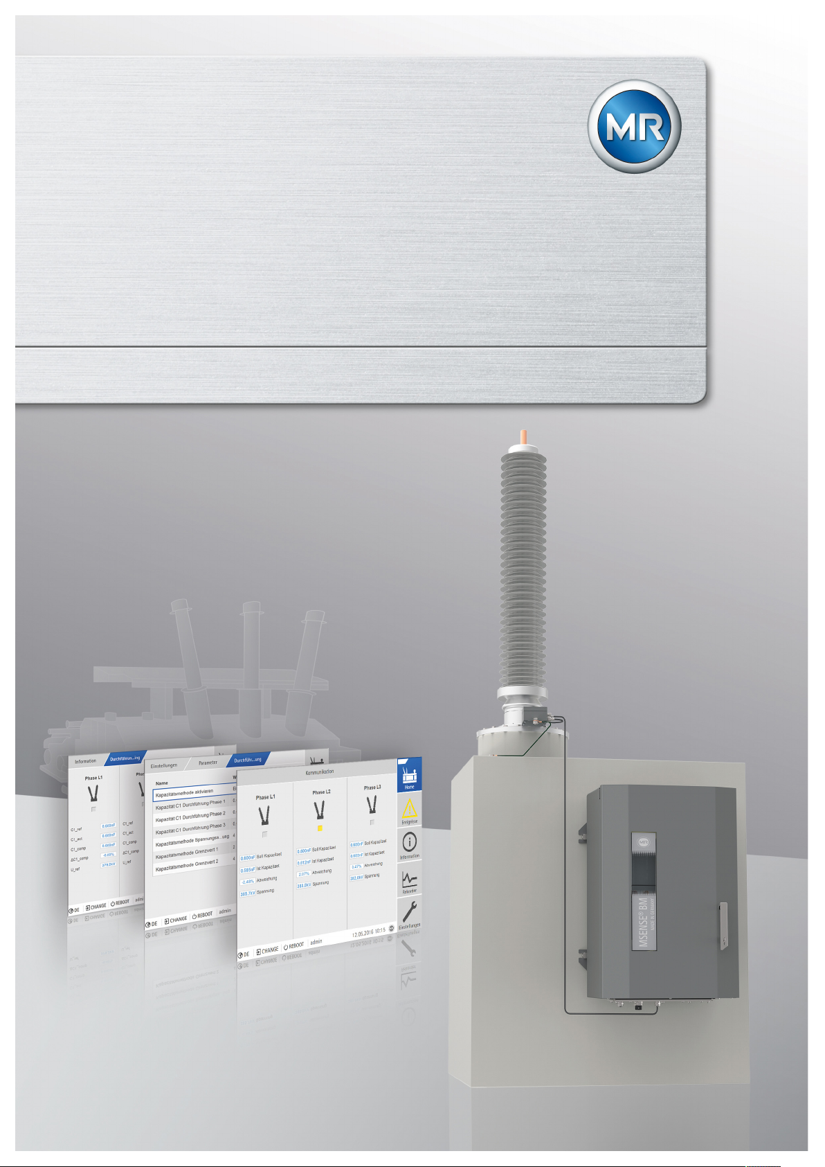
Monitoring system
MSENSE® BM
Operating Instructions
5089542/05 EN
Page 2

© All rights reserved by Maschinenfabrik Reinhausen
Dissemination and reproduction of this document and use and disclosure of its content are strictly prohibited
unless expressly permitted.
Infringements will result in liability for compensation. All rights reserved in the event of the granting of patents,
utility models or designs.
The product may have been altered since this document was published.
We reserve the right to change the technical data, design and scope of supply.
Generally the information provided and agreements made when processing the individual quotations and orders
are binding.
The original operating instructions were written in German.
Page 3

Table of contents
Table of contents
1 Introduction......................................................................................................................... 8
1.1 Manufacturer....................................................................................................................................... 8
1.2 Completeness..................................................................................................................................... 8
1.3 Safekeeping........................................................................................................................................ 8
1.4 Notation conventions .......................................................................................................................... 8
1.4.1 Hazard communication system .............................................................................................................................8
1.4.2 Information system..............................................................................................................................................10
1.4.3 Instruction system ...............................................................................................................................................10
1.4.4 Typographic conventions ....................................................................................................................................11
2 Safety................................................................................................................................. 12
2.1 Appropriate use ................................................................................................................................ 12
2.2 Inappropriate use.............................................................................................................................. 12
2.3 Personnel qualification...................................................................................................................... 13
2.4 Operator's duty of care ..................................................................................................................... 13
3 IT security.......................................................................................................................... 14
4 Product description.......................................................................................................... 17
4.1 Scope of delivery .............................................................................................................................. 17
4.2 Function description.......................................................................................................................... 17
4.3 Performance features ....................................................................................................................... 18
4.4 Operating modes .............................................................................................................................. 19
4.5 Design............................................................................................................................................... 20
4.5.1 Bushing adapter and bushing coupling unit ........................................................................................................21
4.5.2 Control cabinet ....................................................................................................................................................21
5 Packaging, transport and storage ..................................................................................27
5.1 Packaging ......................................................................................................................................... 27
5.1.1 Suitability.............................................................................................................................................................27
5.1.2 Markings..............................................................................................................................................................28
5.2 Transportation, receipt and handling of shipments........................................................................... 28
5.3 Storage of shipments........................................................................................................................ 29
5.4 Unpacking shipments and checking for transportation damages ..................................................... 30
Maschinenfabrik Reinhausen GmbH 2019 35089542/05 EN MSENSE® BM
Page 4

Table of contents
6 Mounting ...........................................................................................................................32
6.1 Preparation ....................................................................................................................................... 32
6.2 Installing the bushing adapter........................................................................................................... 32
6.3 Installing the bushing coupling unit................................................................................................... 34
6.4 Fitting the control cabinet to the transformer .................................................................................... 37
6.5 Connecting the device ...................................................................................................................... 39
6.5.1 Cable recommendation .......................................................................................................................................39
6.5.2 Information about connecting serial interfaces RS232 and RS485.....................................................................40
6.5.3 Information about laying fiber-optic cable ...........................................................................................................43
6.5.4 Connecting the bushing adapter to the bushing coupling unit ............................................................................43
6.5.5 Connecting the bushing coupling unit to the control cabinet...............................................................................44
6.5.6 Connecting the voltage transformers for the reference system ..........................................................................49
6.5.7 Connecting additional leads (optional) ................................................................................................................50
6.5.8 Connecting the power supply..............................................................................................................................51
6.6 Checking functional reliability ........................................................................................................... 52
7 Commissioning................................................................................................................. 53
7.1 Determining the capacitance and dissipation factor of the bushings................................................ 53
7.2 Establishing connection to visualization ........................................................................................... 53
7.3 Setting the language......................................................................................................................... 55
7.4 Setting date and time........................................................................................................................ 56
7.5 Setting the parameters ..................................................................................................................... 56
7.5.1 Commissioning wizard ........................................................................................................................................56
7.5.2 Setting the parameters manually ........................................................................................................................57
7.6 Performing standardization............................................................................................................... 58
7.7 Performing tests................................................................................................................................ 58
7.7.1 Performing function tests ....................................................................................................................................58
7.7.2 Electrical high-voltage tests on the transformer ..................................................................................................59
7.7.3 Dielectric tests on transformer wiring ..................................................................................................................59
8 Operation........................................................................................................................... 60
8.1 Establishing connection to visualization ........................................................................................... 60
8.2 Operating concept ............................................................................................................................ 61
8.3 General ............................................................................................................................................. 63
8.3.1 Activating/deactivating automatic launch of commissioning wizard .................................................................... 63
8.3.2 Setting measured value display ..........................................................................................................................63
Maschinenfabrik Reinhausen GmbH 20194 5089542/05 ENMSENSE® BM
Page 5

Table of contents
8.3.3 Remote behavior.................................................................................................................................................64
8.3.4 Accessing online help .........................................................................................................................................64
8.3.5 Activating/deactivating the USB interface ...........................................................................................................64
8.3.6 Set up automatic logout ......................................................................................................................................64
8.3.7 Activating/deactivating service user access........................................................................................................65
8.4 Configuring the network.................................................................................................................... 66
8.5 Setting the transformer data for the reference system (optional) ..................................................... 68
8.6 Configuring bushing monitoring ........................................................................................................ 68
8.6.1 Set the field designation......................................................................................................................................69
8.6.2 Configuring capacitance monitoring....................................................................................................................69
8.6.3 Configuring dissipation factor monitoring ............................................................................................................72
8.6.4 Circuit breaker monitoring ...................................................................................................................................75
8.7 Displaying the state of the bushings ................................................................................................. 75
8.8 Displaying the capacitance progression ........................................................................................... 76
8.9 Displaying the dissipation factor progression ................................................................................... 77
8.10 Displaying measured value recorder (optional) ................................................................................ 77
8.11 Configuring digital inputs and outputs............................................................................................... 79
8.12 Event management........................................................................................................................... 81
8.12.1 Displaying and acknowledging events ................................................................................................................81
8.12.2 Configuring events ..............................................................................................................................................82
8.12.3 Displaying event memory....................................................................................................................................83
8.13 SCADA ............................................................................................................................................. 84
8.13.1 Configuring IEC 61850 (optional)........................................................................................................................85
8.13.2 Configuring IEC 60870-5-101 (optional) .............................................................................................................87
8.13.3 Configuring IEC 60870-5-103 (optional) .............................................................................................................92
8.13.4 Configuring IEC 60870-5-104 (optional) .............................................................................................................95
8.13.5 Configuring Modbus (optional) ............................................................................................................................97
8.13.6 Configuring DNP3 (optional) .............................................................................................................................100
8.14 Configuring syslog .......................................................................................................................... 104
8.15 Time synchronization ...................................................................................................................... 105
8.15.1 Activating time synchronization using SNTP.....................................................................................................106
8.15.2 Entering the time server address ......................................................................................................................107
8.15.3 Setting the time zone ........................................................................................................................................107
8.15.4 Setting synchronization interval ........................................................................................................................108
8.15.5 Automatic switchover between daylight saving time and standard time ...........................................................108
8.15.6 Setting the date and time manually...................................................................................................................108
Maschinenfabrik Reinhausen GmbH 2019 55089542/05 EN MSENSE® BM
Page 6

Table of contents
8.16 User administration ......................................................................................................................... 109
8.16.1 User roles..........................................................................................................................................................109
8.16.2 Changing password ..........................................................................................................................................110
8.16.3 Creating, editing and deleting users..................................................................................................................111
8.16.4 Setting access rights to parameters and events ...............................................................................................113
8.16.5 User authentication via RADIUS (optional) .......................................................................................................114
8.17 Information about device ................................................................................................................ 116
8.17.1 Hardware...........................................................................................................................................................116
8.17.2 Software ............................................................................................................................................................117
8.18 Import/export manager ................................................................................................................... 117
8.18.1 Exporting data ...................................................................................................................................................117
8.18.2 Importing data (software version 3.44 and later)...............................................................................................119
8.19 Linking signals and events.............................................................................................................. 120
8.19.1 Linking digital outputs and control system messages .......................................................................................120
9 Inspection and maintenance ......................................................................................... 123
9.1 Care ................................................................................................................................................ 123
9.2 Inspection ....................................................................................................................................... 123
9.3 Maintenance ................................................................................................................................... 123
10 Fault elimination .............................................................................................................124
10.1 General faults ................................................................................................................................. 124
10.2 Signal lights and digital outputs ...................................................................................................... 124
10.3 Human-machine interface............................................................................................................... 125
10.4 Other faults ..................................................................................................................................... 125
11 Messages ........................................................................................................................127
11.1 Event messages ............................................................................................................................. 127
12 Uninstallation.................................................................................................................. 138
12.1 Removing the control cabinet ......................................................................................................... 138
12.2 Removing the bushing adapter and bushing coupling unit ............................................................. 140
13 Disposal........................................................................................................................... 142
14 Technical data................................................................................................................. 143
14.1 Bushing adapter.............................................................................................................................. 143
14.2 Bushing coupling unit...................................................................................................................... 146
Maschinenfabrik Reinhausen GmbH 20196 5089542/05 ENMSENSE® BM
Page 7

Table of contents
14.3 Control cabinet................................................................................................................................ 147
14.3.1 Connection terminals ........................................................................................................................................148
14.3.2 Voltage measurement UI5-3 ............................................................................................................................149
14.3.3 DIO28-15 digital inputs and outputs.................................................................................................................150
14.3.4 CPU (central processing unit) I .........................................................................................................................151
14.3.5 System networking............................................................................................................................................154
14.3.6 Bus extension module.......................................................................................................................................155
14.4 Connection cable ............................................................................................................................ 155
15 Appendix ......................................................................................................................... 157
15.1 Measured value log ........................................................................................................................ 157
Glossary .......................................................................................................................... 159
List of key words ............................................................................................................ 160
Maschinenfabrik Reinhausen GmbH 2019 75089542/05 EN MSENSE® BM
Page 8

1 Introduction
1 Introduction
This technical file contains detailed descriptions on the safe and proper installation, connection, commissioning and monitoring of the product.
It also includes safety instructions and general information about the product.
This technical file is intended solely for specially trained and authorized personnel.
1.1 Manufacturer
The product is manufactured by:
Maschinenfabrik Reinhausen GmbH
Falkensteinstraße 8
93059 Regensburg, Germany
Tel.: (+49) 9 41/40 90-0
Fax: (+49) 9 41/40 90-7001
E-mail: sales@reinhausen.com
Further information on the product and copies of this technical file are available from this address if required.
1.2 Completeness
This technical file is incomplete without the supporting documents.
The following documents are considered supporting documents:
▪ Connection diagrams
▪ Supplement (optional)
1.3 Safekeeping
Keep this technical file and all supporting documents ready at hand and accessible for future use at all times.
1.4 Notation conventions
This section contains an overview of the symbols and textual emphasis
used.
1.4.1 Hazard communication system
Warnings in this technical file are displayed as follows.
Maschinenfabrik Reinhausen GmbH 20198 5089542/05 ENMSENSE® BM
Page 9
1 Introduction
1.4.1.1 Warning relating to section
Warnings relating to sections refer to entire chapters or sections, sub-sections or several paragraphs within this technical file. Warnings relating to
sections use the following format:
WARNING
Type of danger!
Source of the danger and outcome.
► Action
► Action
1.4.1.2 Embedded warning information
Embedded warnings refer to a particular part within a section. These warnings apply to smaller units of information than the warnings relating to sections. Embedded warnings use the following format:
DANGER! Instruction for avoiding a dangerous situation.
1.4.1.3 Signal words and pictograms
The following signal words are used:
Signal word Definition
DANGER Indicates a hazardous situation which, if not avoided, will result in
death or serious injury.
WARNING Indicates a hazardous situation which, if not avoided, could result
in death or serious injury.
CAUTION Indicates a hazardous situation which, if not avoided, could result
in minor or moderate injury.
NOTICE Indicates measures to be taken to prevent damage to property.
Table1: Signal words in warning notices
Pictograms warn of dangers:
Pictogram Definition
Warning of a danger point
Warning of dangerous electrical voltage
Maschinenfabrik Reinhausen GmbH 2019 95089542/05 EN MSENSE® BM
Page 10
Pictogram Definition
Warning of combustible substances
Warning of danger of tipping
Warning of danger of crushing
Table2: Pictograms used in warning notices
1 Introduction
1.4.2 Information system
Information is designed to simplify and improve understanding of particular
procedures. In this technical file it is laid out as follows:
Important information.
1.4.3 Instruction system
This technical file contains single-step and multi-step instructions.
Single-step instructions
Instructions which consist of only a single process step are structured as follows:
Aim of action
ü Requirements (optional).
► Step 1 of 1.
ð Result of step (optional).
ð Result of action (optional).
Multi-step instructions
Instructions which consist of several process steps are structured as follows:
Maschinenfabrik Reinhausen GmbH 201910 5089542/05 ENMSENSE® BM
Page 11

1 Introduction
Aim of action
ü Requirements (optional).
1. Step 1.
ð Result of step (optional).
2. Step 2.
ð Result of step (optional).
ð Result of action (optional).
1.4.4 Typographic conventions
The following typographic conventions are used in this technical file:
Typographic convention Purpose Example
UPPERCASE Operating controls, switches ON/OFF
[Brackets] PC keyboard [Ctrl] + [Alt]
Bold Software operating controls Press Continue button
…>…>… Menu paths Parameter > Control parameter
Italics System messages, error messages,
signals
[► Number of pages]. Cross reference [► 41].
Table3: Typographic conventions
Function monitoring alarm triggered
Maschinenfabrik Reinhausen GmbH 2019 115089542/05 EN MSENSE® BM
Page 12

2 Safety
2.1 Appropriate use
The product is a monitoring system and is used to monitor capacitancegraded bushings on power transformers in the Um = 123...420 kV voltage
levels (with voltage levels up to 765 kV on request). You can use the product
to detect breakdowns at partial capacitances in the bushing and to monitoring aging in the bushings.
The product is designed solely for use in electrical energy systems and facilities. It may be used only if you observe the requirements and conditions
listed in this technical file as well as the warnings in this technical file and the
warnings posted on the product. This applies across the entire service life of
the product, from delivery to installation and operation through to disassembly and disposal.
The following is considered appropriate use:
▪ Use the product only with the bushings specified in the order.
▪ Use the product only for high-voltage transformer bushings and subject to
similar installation conditions and thermal loads.
▪ Use the product only for bushings of the same type (manufacturer, series,
technology, model year)
▪ Use the product only for bushings that were not previously damaged.
▪ Operate the product in accordance with this technical file, the agreed-
upon delivery conditions and the technical data.
▪ Ensure that all necessary work is performed by qualified personnel only.
▪ Only use the equipment and special tools included in delivery for the in-
tended purpose and in accordance with the specifications of this technical
file.
▪ Only operate the product in industrial areas. Observe the notes in this
technical file regarding electromagnetic compatibility and the technical
data.
2 Safety
2.2 Inappropriate use
Use is considered to be inappropriate if the product is used other than as described in the Appropriate use section. In addition, observe the following:
▪ The product is not suited for extending the permitted service life of the
bushing specified by the bushing manufacturer.
▪ The product is not a protective device. Do not use it to handle safety-re-
lated functions.
▪ Risk of explosion and fire from highly flammable or explosive gases, va-
pors, or dusts. Do not operate the product in areas at risk of explosion.
▪ The product is not intended for use in environments subject to strong cor-
rosion effects.
Maschinenfabrik Reinhausen GmbH 201912 5089542/05 ENMSENSE® BM
Page 13

2 Safety
▪ Unauthorized or inappropriate changes to the product may lead to per-
sonal injury, material damage and operational faults. Only modify the
product after consultation with Maschinenfabrik Reinhausen GmbH.
▪ Do not connect the product components to measurement systems from
other manufacturers, because this can lead to bushing monitoring errors.
2.3 Personnel qualification
The product is designed solely for use in electrical energy systems and facilities operated by appropriately trained staff. This staff comprises people who
are familiar with the installation, assembly, commissioning and operation of
such products.
2.4 Operator's duty of care
To prevent accidents, disruptions and damage as well as unacceptable adverse effects on the environment, those responsible for transport, installation, operation, maintenance and disposal of the product or parts of the product must ensure the following:
▪ All warning and hazard notices are complied with.
▪ Personnel are instructed regularly in all relevant aspects of operational
safety, the operating instructions and particularly the safety instructions
contained therein.
▪ Regulations and operating instructions for safe working as well as the rel-
evant instructions for staff procedures in the case of accidents and fires
are kept on hand at all times and are displayed in the workplace where
applicable.
▪ The product is only used when in a sound operational condition and safety
equipment in particular is checked regularly for operational reliability.
▪ Only replacement parts, lubricants and auxiliary materials which are au-
thorized by the manufacturer are used.
▪ The specified operating conditions and requirements of the installation lo-
cation are complied with.
▪ All necessary devices and personal protective equipment for the specific
activity are made available.
▪ The prescribed maintenance intervals and the relevant regulations are
complied with.
▪ Installation, electrical connection and commissioning of the product may
only be carried out by qualified and trained personnel in accordance with
this technical file.
▪ The operator must ensure appropriate use of the product.
Maschinenfabrik Reinhausen GmbH 2019 135089542/05 EN MSENSE® BM
Page 14

3 IT security
3 IT security
Observe the following recommendations for secure operation of the product.
General
▪ Ensure that only authorized personnel have access to the device.
▪ Only use the device within an ESP (electronic security perimeter). Do not
connect the device to the Internet in an unprotected state. Use mechanisms for vertical and horizontal network segmenting and security gateways (firewalls) at the transition points.
▪ Ensure that the device is only operated by trained personnel who are fa-
miliar with IT security.
Commissioning
Observe the following recommendations for device commissioning:
▪ User IDs must be unique and assignable. Do not use a "Group account"
function or the "Auto login" function.
▪ Activate the "Auto logout [►Section 8.3.6, Page 64]" function.
▪ Restrict the rights of the individual user groups as much as is feasible; this
helps avoid errors during operations. A user with the "Operator" role, for
example, should only perform operations and should not be able to
change any device settings.
▪ Delete or disable the default "admin" user ID. This requires first creating a
new user account with the "Administrator" role. You can then use it to
delete or disable the default "admin" account.
▪ Deactivate service user access [►Section 8.3.7, Page 65].
▪ Enable SSL/TLS encryption [►Section 8.3, Page 63]; access to the de-
vice is then only possible using the SSL/TLS protocol. In addition to encrypting communication, this protocol also checks the authenticity of the
server.
▪ Use TLS version 1.2 or higher wherever possible.
▪ Integrate the device into a public key infrastructure. Create your own SSL
certificates for this if necessary and then import it.
▪ Connect the device to a central log server by using the syslog interface
[►Section 8.14, Page 104].
Operation
Observe the following recommendations during device operation:
▪ Change the password at regular intervals.
▪ Export the security log [►Section 8.18.1, Page 117] at regular intervals.
▪ Check the log files regularly for unauthorized system access and other se-
curity-related events.
Maschinenfabrik Reinhausen GmbH 201914 5089542/05 ENMSENSE® BM
Page 15
3 IT security
Interfaces
The device uses the following interfaces for communication:
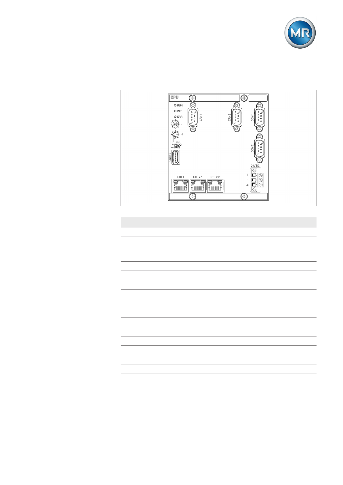
Figure1: Interfaces of the CPU assembly
Interface Protocol Port Description
CAN 1 - - Connection of the DIO assembly
CAN 2 - - Communication with other ISM® devices
(e.g. parallel operation)
COM 1 - - Internal system interface
COM 2 - - Serial interface (SCADA)
USB - - Import or export of data
ETH 1 TCP 102 IEC61850
ETH 1 TCP 502 Modbus
ETH 1 TCP 20000 DNP3
2)
2)
ETH 1 UDP 67 DHCP server
ETH 2.x TCP 21 FTP1) (only for MR service)
ETH 2.x TCP 80 HTTP for web-based visualization
ETH 2.x TCP 443 HTTPS for web-based visualization
1)
1)
ETH 2.x TCP 990 FTPS (only for MR service)
ETH 2.x TCP 8080 HTTP for web-based visualization
ETH 2.x TCP 8081 HTTPS for web-based visualization
Table4: Interfaces and open ports of the CPU assembly
1)
1)
1)
Port is closed if you activate the device's SSL encryption.
2)
Default setting; if you have modified the port for the control system proto-
col, only the set port is opened.
Maschinenfabrik Reinhausen GmbH 2019 155089542/05 EN MSENSE® BM
Page 16

3 IT security
Encryption standards
The device supports the following TLS versions:
▪ TLS 1.0
▪ TLS 1.1
▪ TLS 1.2
The device uses the following cipher suites for a TLS-secured connection:
Key exchange Authentication Encryption Key length Operating
mode
Hash func-
tion
TLS ECDHE RSA WITH AES 128 CBC SHA
DHE SHA265
ECDHE ECDSA GCM SHA256
ECDH 256 CBC SHA
1)
RSA
SHA256
GCM SHA384
Table5: Cipher suite
1)
Not available with TLS version >= 1.2
The device uses the SHA256 hash function to save passwords.
Also refer to
2 Exporting data [►117]
2 General [►63]
1)
1)
Maschinenfabrik Reinhausen GmbH 201916 5089542/05 ENMSENSE® BM
Page 17

4 Product description
4 Product description
This chapter contains an overview of the design and function of the product.
4.1 Scope of delivery
The following items are included in the delivery:
▪ Control cabinet with MSENSE® BM bushing monitoring
▪ For each bushing to be monitored (3 or 6):
– Bushing adapter
– Connection cable for the bushing adapter and bushing coupling unit
– Bushing coupling unit
– Set of fasteners for the bushing coupling unit
– Connection cable for the bushing coupling unit and ISM® control cabi-
net
▪ Technical documentation
Please note the following:
▪ Check the shipment for completeness on the basis of the shipping docu-
ments.
▪ Store the parts in a dry place until installation.
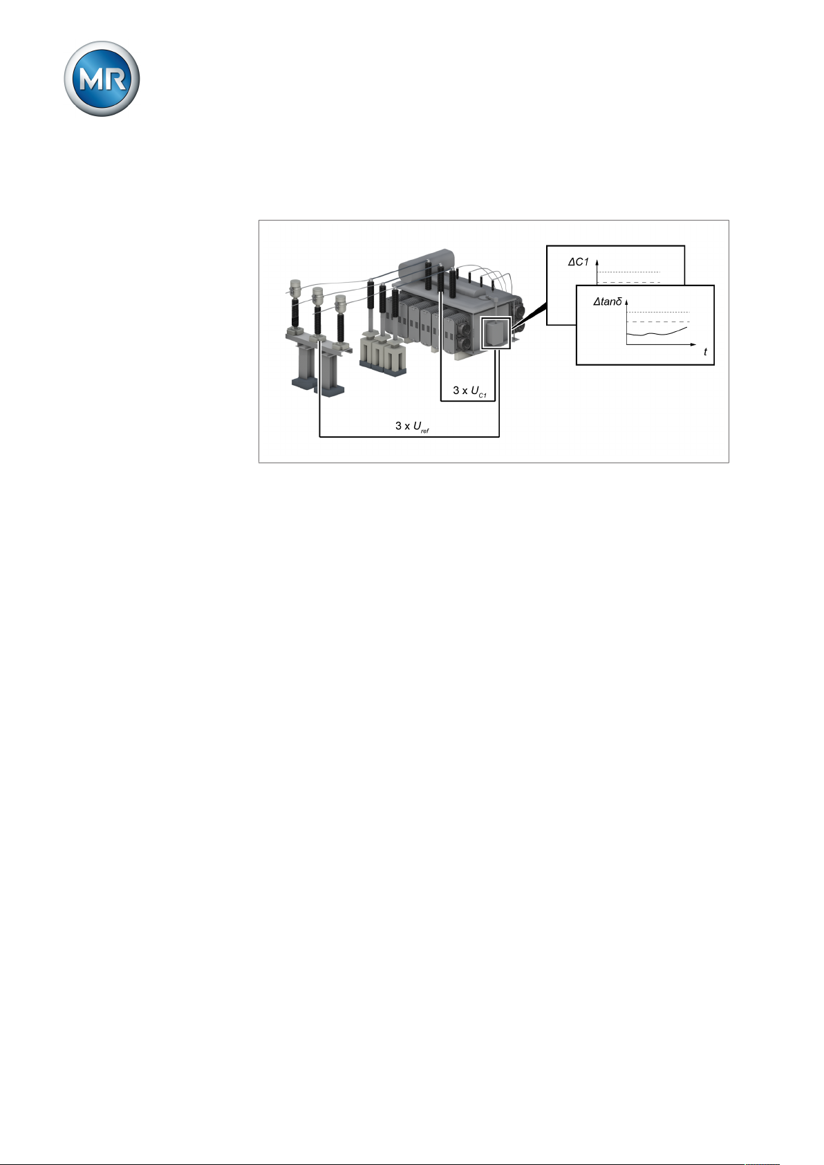
4.2 Function description
The product is a monitoring system and is used to monitor capacitance
graded bushings on power transformers. You can use the product to detect
breakdowns at partial capacitances in the bushings and to monitor aging in
the bushings.
In order to evaluate the state of the bushing, the bushings are equipped with
a measuring device with which the system can continuously determine the
change in capacitance ΔC1 and the change in dissipation factor Δtanδ of the
bushings during operation. In addition, the system records the voltage of the
3-phase reference system.
Maschinenfabrik Reinhausen GmbH 2019 175089542/05 EN MSENSE® BM
Page 18
4 Product description
The monitoring system takes advantage of the implemented algorithms to
largely compensate for voltage fluctuations and temperature fluctuations in
the 3-phase system, thereby ensuring reliable monitoring for the bushings.
Figure2: Operating principle
4.3 Performance features
The MSENSE® BM monitoring system monitors the bushings of a power
transformer and has the following features:
▪ Monitoring of oil-impregnated paper bushings (OIP) and resin-impreg-
nated paper bushings (RIP) at voltage levels of Um = 123...420 kV (with
voltage levels up to 765 kV on request)
▪ Optional: Monitoring of 6 bushings, where 3 bushings each form one set
(field 1 and field 2)
▪ Online monitoring of the bushing by means of capacitance measurement
and dissipation factor measurement
– Monitoring the change in capacitance C1
– Monitoring the change in the dissipation factor tanδ
– 3-phase reference system (e.g. voltage transformer)
– Compensation for temperature fluctuations
– Compensation for the effects of weather
– Compensation for voltage fluctuations
– Compensation for grid asymmetry
▪ Display of the measured and calculated values
▪ Status messages via digital outputs
▪ Web-based visualization
▪ SCADA
– IEC 60870-5-101
– IEC 60870-5-103
– IEC 60870-5-104
Maschinenfabrik Reinhausen GmbH 201918 5089542/05 ENMSENSE® BM
Page 19

4 Product description
– IEC 61850 (edition 1 and edition 2)
– Modbus (RTU, TCP, ASCII)
– DNP3
4.4 Operating modes
Local mode (LOCAL)
In the Local operating mode, you can make entries and input commands using the device's operating controls. You cannot use inputs or the control system to make entries or enter commands.
Remote mode (REMOTE)
In the Remote operating mode, you can make entries and carry out commands using digital inputs or the control system, depending on the setting of
the Remote behavior [►Section 8.3.3, Page 64] parameter.
Maschinenfabrik Reinhausen GmbH 2019 195089542/05 EN MSENSE® BM
Page 20
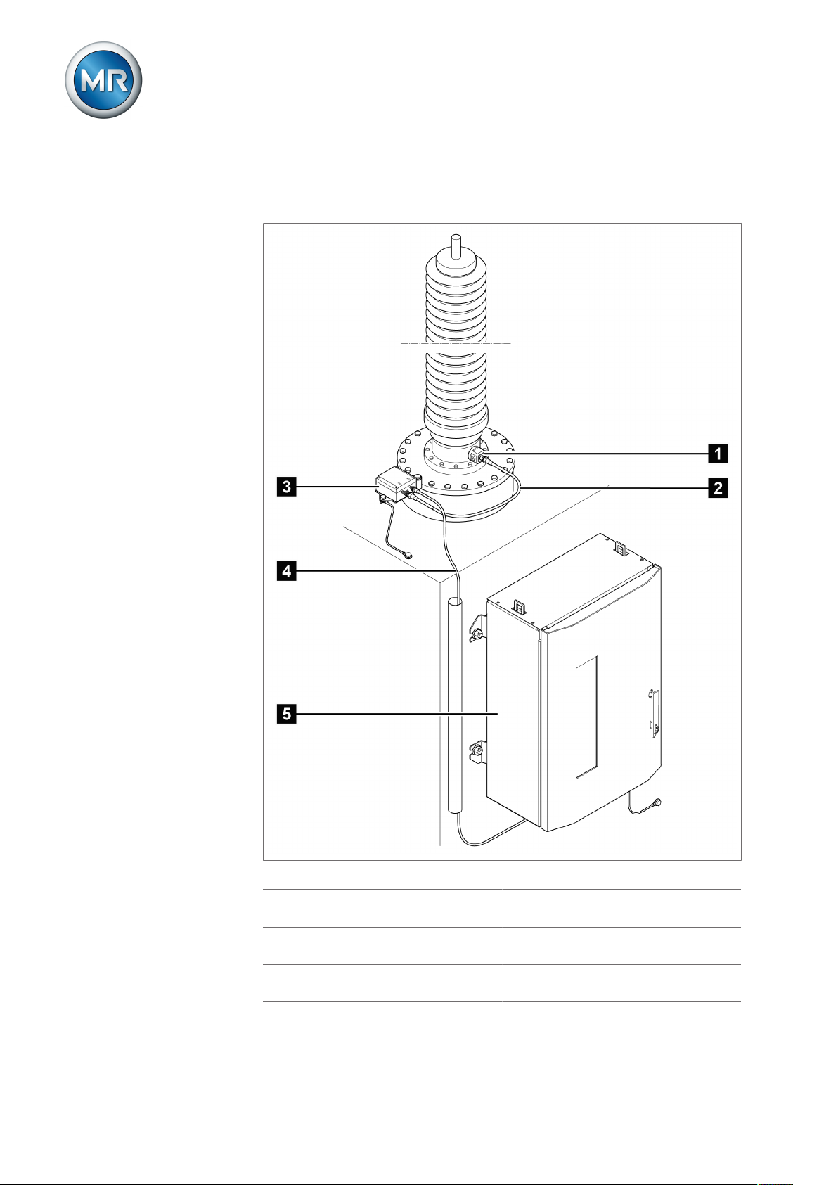
4.5 Design
The complete system consists of the following subassemblies:
4 Product description
Figure3: Design
1 Bushing adapter 2 Connection cable for the bushing
adapter and bushing coupling unit
3 Bushing coupling unit 4 Connection cable for the bushing
coupling unit and control cabinet
5 Control cabinet with monitoring
system
Maschinenfabrik Reinhausen GmbH 201920 5089542/05 ENMSENSE® BM
Page 21

4 Product description
4.5.1 Bushing adapter and bushing coupling unit
The bushing adapter is used to pick up the measured voltage at the bushing
test tap. The downstream bushing coupling unit is used to adjust the measured voltage. Both components are tuned to the bushings to be monitored
in accordance with your order. They may be used only for those bushings.
The following components are used:
▪ Bushing adapter (A001...A008)
▪ C002: Bushing coupling unit
Type Bushing types
A001 Micafil RTKF
Micafil RTKG
A002 HSP SETFt 1550/420-1800
HSP SETFt 600/123-2000
A003 ABB GOB 1050-750-1100-0.6-B
ABB GSA 123-OA/1600/0.5
ABB GSA 52-OA/2000/0.5
A004 Trench COT 750-800
A005 HSP SETFt 750-170-4000
HSP SETFt 1200/245-1250
HSP SETFt 1425-420-1600
HSP SESTFt 1050-245-B E6 B
HSP SESTFt 1425-420-B E6 B-1600A
HSP EKTG 72.5-800 kV
A006 PCORE CSA standard POC ser. 2
ABB GOE, GSB (245...550kV)
A007 PCORE B-81515-57-70
A008 Passoni Villa PNO, POBO, PCTO, PAO < 110 kV
Table6: Bushing adapter
4.5.2 Control cabinet
The control cabinet contains the control system for monitoring the bushings
as well as various display elements and operating controls.
Maschinenfabrik Reinhausen GmbH 2019 215089542/05 EN MSENSE® BM
Page 22
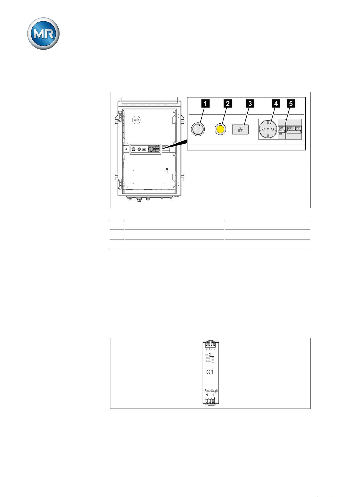
4.5.2.1 Display elements and operating controls
The control cabinet contains the following components:
4 Product description
Figure4: Control cabinet display elements and operating controls
1 Local/Remote switch 2 Signal light (yellow, red)
3 Ethernet interface ETH1.1 (RJ45) 4 Plug socket X19, max. 10 A
5 Fuses F14 and F25
4.5.2.2 Assemblies
Depending on configuration, the device may have various assemblies which
perform the functions required. The functions of the assemblies are described in the following sections. You will find more information about the assemblies in the Technical data [►Section 14, Page 143] section.
4.5.2.2.1 Power supply
The G1 PULS DIMENSION QS3.241 assembly supplies power to the device.
Figure5: G1 PULS DIMENSION QS3.241 assembly
Maschinenfabrik Reinhausen GmbH 201922 5089542/05 ENMSENSE® BM
Page 23
4 Product description
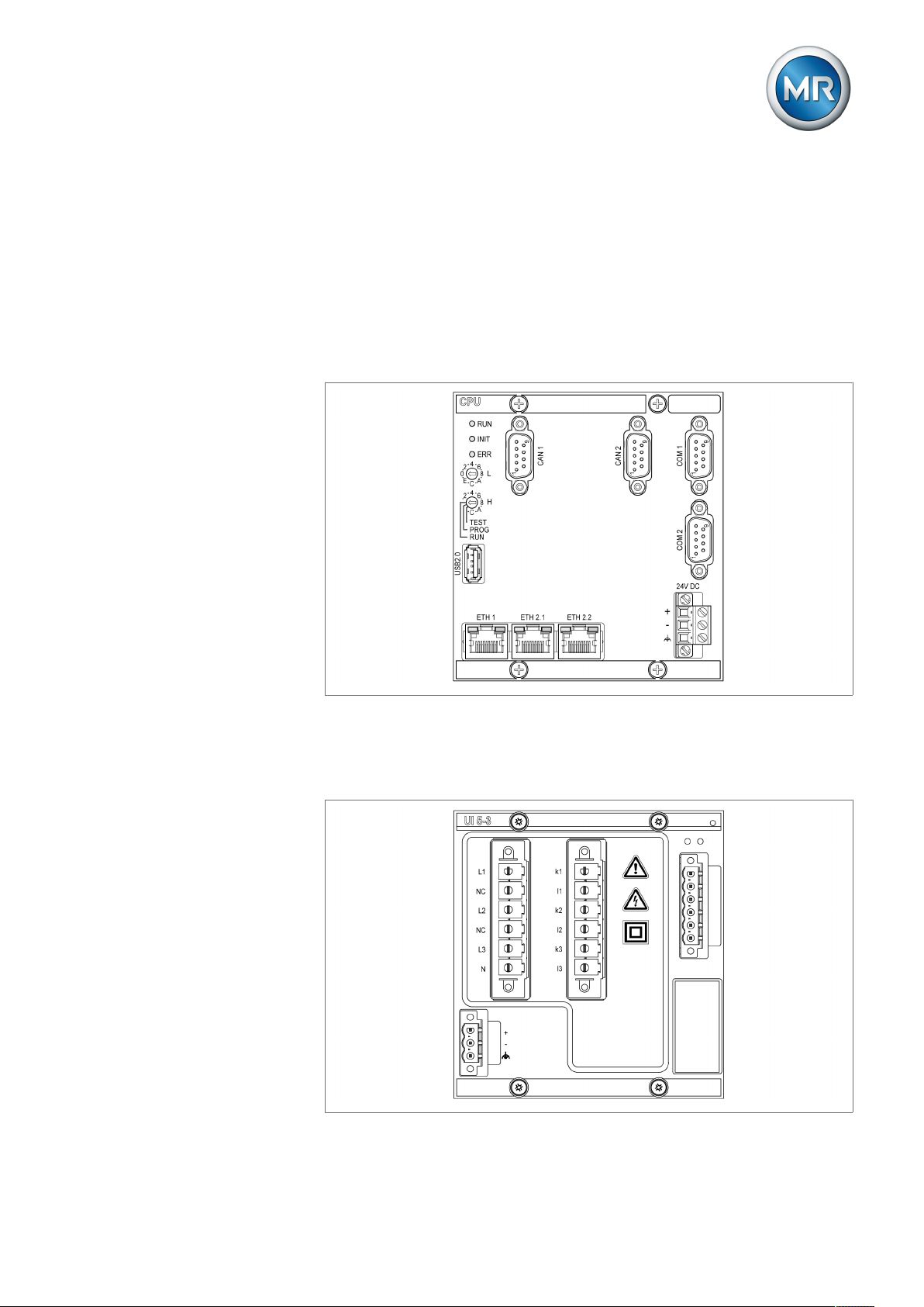
4.5.2.2.2 CPU (central processing unit) I
The CPU I assembly is the central computing unit for the device. It contains
the following interfaces:
▪ Internal system interface RS232 (COM1)
▪ Serial interface RS232/485 (COM2)
▪ 3x Ethernet (ETH1, ETH 2.1, ETH 2.2)
▪ USB (USB 2.0)
▪ 2x CAN bus (CAN 1, CAN 2)
Figure6: CPU I assembly
4.5.2.2.3 Voltage measurement
The UI5-3 assembly is used for measuring 3-phase voltage.
Figure7: UI 5-3 assembly
Maschinenfabrik Reinhausen GmbH 2019 235089542/05 EN MSENSE® BM
Page 24
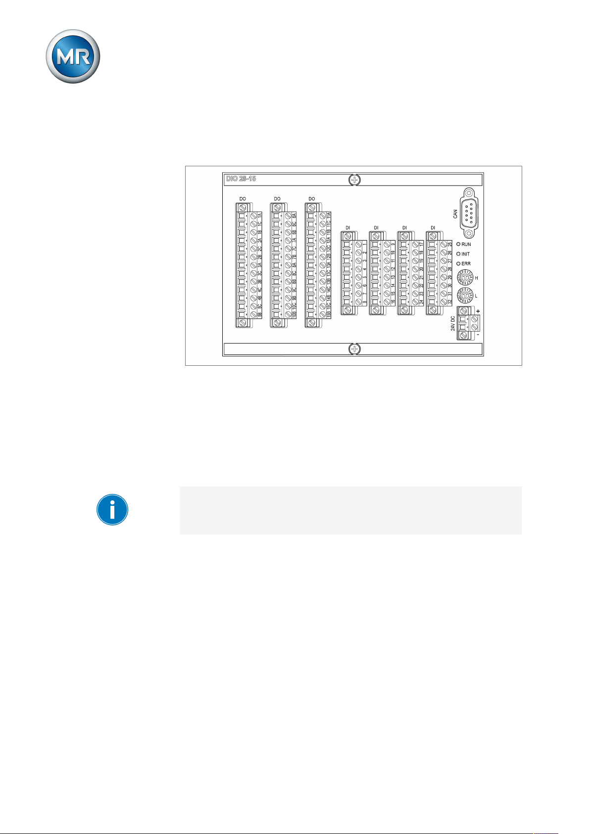
4.5.2.2.4 DIO28-15 digital inputs and outputs
The DIO 28-15 assembly makes 28 inputs and 15 outputs (6 N/O contacts, 9
change-over contacts) available.
4 Product description
Figure8: DIO 28-15 assembly
4.5.2.2.5 Media converter
The MC 2-2 assembly is a media converter, which converts 2 electrical connections (RJ45) to one fiber-optic cable connection each. Each is converted
independently of the other. The following interfaces are available:
▪ 2x RJ45 (ETH12, ETH22)
▪ 2x Duplex-LC (SFP module) (ETH11, ETH21)
The media converter is designed to be transparent for the network and does
not have its own IP address.
Maschinenfabrik Reinhausen GmbH 201924 5089542/05 ENMSENSE® BM
Page 25
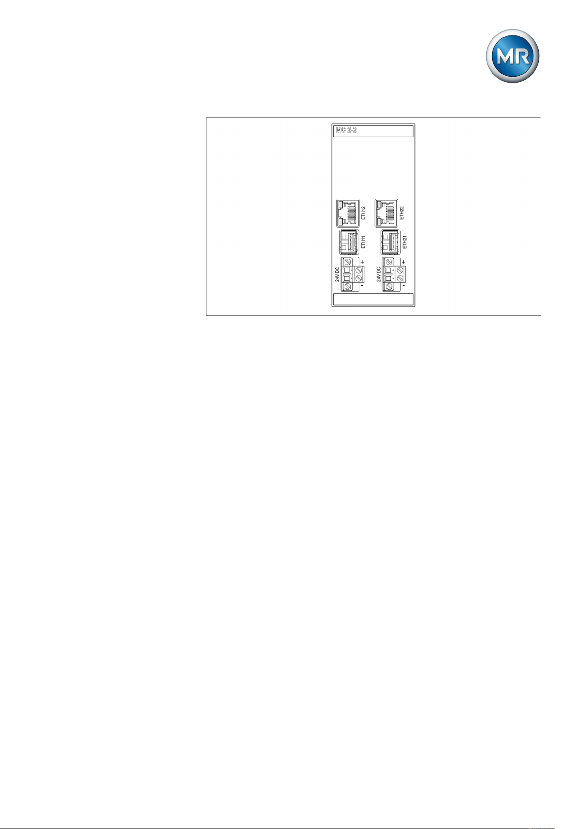
4 Product description
Figure9: MC 2-2 assembly
4.5.2.2.6 Media converter with managed switch
The assembly SW 3-3 is a media converter with managed switch. It combines two independent functions and provides you with the following interfaces:
▪ A media converter converts an electric connection (RJ45) into a fiber-optic
cable connection
– RJ45 (ETH12)
– Duplex-LC (SFP module) (ETH11)
▪ Managed switch with redundancy function (PRP or RSTP)
– 2x RJ45 (ETH23, ETH24), device-internal connection
– 2x Duplex-LC (SFP module) (ETH21, ETH22), redundancy connection
The following redundancy functions are available to you according to your
order:
▪ PRP (standard setting)
▪ RSTP
Maschinenfabrik Reinhausen GmbH 2019 255089542/05 EN MSENSE® BM
Page 26
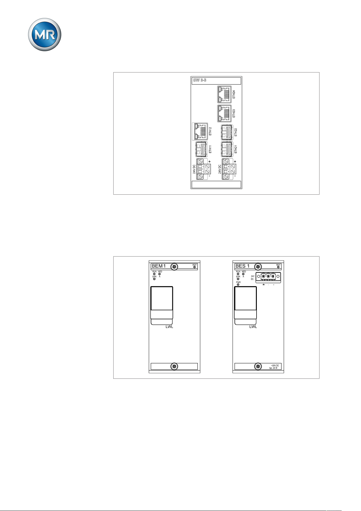
Figure10: SW 3-3 assembly
4 Product description
4.5.2.2.7 Bus extension module
The assemblies BEM 1 (master) and BES 1 (slave) are bus extension modules which are used to extend the system by one additional busbar with additional assemblies. Data is transmitted via fiber-optic cable. The assembly
BES 1 has a connection for supplying voltage to the additional busbar.
Figure11: Assemblies BEM 1 and BES 1
Maschinenfabrik Reinhausen GmbH 201926 5089542/05 ENMSENSE® BM
Page 27

5 Packaging, transport and storage
5 Packaging, transport and storage
5.1 Packaging
The products are sometimes supplied with sealed packaging and sometimes
in a dry state, depending on requirements.
Sealed packaging surrounds the packaged goods with plastic foil on all
sides.
Products that have also been dried are identified by a yellow label on the
sealed packaging. In the dry state, delivery is also possible in a transport
container.
The information in the following sections should be applied as appropriate.
5.1.1 Suitability
NOTICE
Property damage due to incorrectly stacked crates!
Stacking the crates incorrectly can lead to damage to the packaged goods.
► The outer marking on the packaging states if, for example, the on-load
tap-changer or selector has been packed upright. Never stack these
crates.
► General rule: Do not stack crates above a height of 1.5 m.
► For other crates: Only stack up to 2 equally sized crates on top of one an-
other.
The packaging is suitable to ensure undamaged and fully functional means
of transportation in compliance with local transportation laws and regulations.
The packaged goods are packed in a sturdy crate. This crate ensures that,
when in the intended transportation position, the packaged goods are stabilized to prevent impermissible changes in position, and that none of the parts
touch the loading surface of the means of transport or touch the ground after
unloading.
Sealed packaging surrounds the packaged goods with plastic foil on all
sides. The packaged goods are protected from humidity using a desiccant.
The plastic foil was bonded after the desiccant is added.
Maschinenfabrik Reinhausen GmbH 2019 275089542/05 EN MSENSE® BM
Page 28
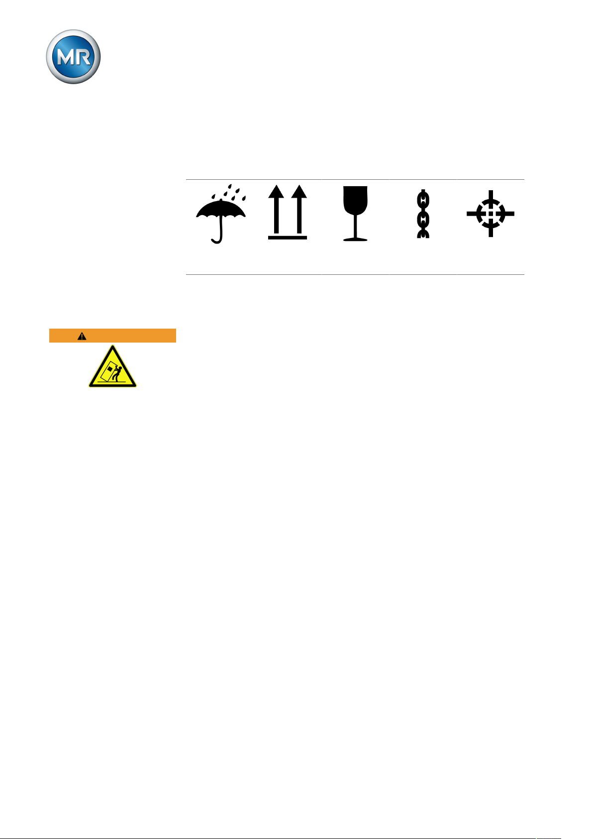
5.1.2 Markings
The packaging bears a signature with instructions for safe transport and correct storage. The following symbols apply to the shipment of non-hazardous
goods. Adherence to these symbols is mandatory.
5 Packaging, transport and storage
WARNING
Protect against
moisture
Table7: Shipping pictograms
Top Fragile Attach lifting
gear here
Center of mass
5.2 Transportation, receipt and handling of shipments
Danger of death or severe injury!
Danger of death or serious injuries due to tipping or falling load.
► Only transport the crate when closed.
► Do not remove the securing material used in the crate during transport.
► If the product is delivered on a pallet, secure it sufficiently.
► Only trained and authorized persons may select the sling gear and se-
cure the load.
► Do not walk under the suspended load.
► Use means of transport and lifting gear with a sufficient carrying capacity
in accordance with the weight stated on the delivery slip.
In addition to oscillation stress, jolts must also be expected during transportation. In order to prevent possible damage, avoid dropping, tipping,
knocking over and colliding with the product.
If a crate tips over, falls from a certain height (e.g. when slings tear) or is
subject to an unbroken fall, damage must be expected regardless of the
weight.
Every delivered shipment must be checked for the following by the recipient
before acceptance (acknowledgment of receipt):
▪ Completeness based on the delivery slip
▪ External damage of any type
The checks must take place after unloading when the crate or transport container can be accessed from all sides.
Maschinenfabrik Reinhausen GmbH 201928 5089542/05 ENMSENSE® BM
Page 29

5 Packaging, transport and storage
Visible damage If external transport damage is found upon receipt of the shipment, proceed
as follows:
▪ Immediately record the identified transport damage in the shipping docu-
ments and have this countersigned by the carrier.
▪ In the event of severe damage, total loss or high damage costs, immedi-
ately notify the manufacturer and the relevant insurance company.
▪ After identifying damage, do not modify the condition of the shipment fur-
ther and retain the packaging material until an inspection decision has
been made by the transport company or the insurance company.
▪ Record the details of the damage immediately on site together with the
carrier involved. This is essential for any claim for damages.
▪ Photograph damage to packaging and packaged goods. This also applies
to signs of corrosion on the packaged goods due to moisture inside the
packaging (rain, snow, condensation).
▪ NOTICE! If the product is delivered in sealed packaging, inspect this im-
mediately. If the sealed packaging is damaged, do not under any circumstances install or commission the packaged goods. Either re-dry the dried
packaged goods as per the operating instructions, or contact the manufacturer to agree on how to proceed. Failure to do so may result in damage to the packaged goods.
▪ Identify the damaged parts.
Hidden damage When damages are not determined until unpacking after receipt of the ship-
ment (hidden damage), proceed as follows:
▪ Make the party responsible for the damage liable as soon as possible by
telephone and in writing, and prepare a damage report.
▪ Observe the time periods applicable to such actions in the respective
country. Inquire about these in good time.
With hidden damage, it is very hard to make the transportation company (or
other responsible party) liable. Any insurance claims for such damages can
only be successful if relevant provisions are expressly included in the insurance terms and conditions.
5.3 Storage of shipments
Packaged goods dried by Maschinenfabrik Reinhausen
Upon receipt of the shipment, immediately remove the packaged goods
dried by Maschinenfabrik Reinhausen from the sealed packaging and store
air-tight in dry insulating fluid until used if the packaged goods were not supplied in insulating fluid.
Non-dried packaged goods
Non-dried packaged goods but with a functional sealed packaging can be
stored outdoors when the following conditions are complied with.
Maschinenfabrik Reinhausen GmbH 2019 295089542/05 EN MSENSE® BM
Page 30
5 Packaging, transport and storage
When selecting and setting up the storage location, ensure the following:
▪ Protect stored goods against moisture (flooding, water from melting snow
and ice), dirt, pests such as rats, mice, termites and so on, and against
unauthorized access.
▪ Store the crates on timber beams and planks as a protection against ris-
ing damp and for better ventilation.
▪ Ensure sufficient carrying capacity of the ground.
▪ Keep entrance paths free.
▪ Check stored goods at regular intervals. Also take appropriate action after
storms, heavy rain or snow and so on.
Protect the packaging foil from direct sunlight so that it does not disintegrate
under the influence of UV rays, which would cause the packaging to lose its
sealing function.
If the product is installed more than 6 months after delivery, suitable measures must be taken without delay. The following measures can be used:
▪ Correctly regenerate the drying agent and restore the sealed packaging.
▪ Unpack the packed goods and store in a suitable storage space (well ven-
tilated, as dust-free as possible, humidity < 50% where possible).
WARNING
5.4 Unpacking shipments and checking for transportation
damages
▪ NOTICE! Transport the packaged crate to the place where installation will
take place. Do not open the sealed packaging until just before installation.
Otherwise, damage to the packaged goods may occur due to ineffectively
sealed packaging.
▪ WARNING! When unpacking, check the condition of the packaged
goods. Place packaged goods in an upright crate and protect against tipping out. If this is not done, the packaged goods may be damaged and serious injuries may result.
▪ Check completeness of accessories based on the delivery slip.
Attachment points for lifting gear
Risk of tipping and danger of falling load!
Danger of death and damage to property due to tipping or falling load.
► Only trained and appointed persons may select the sling gear and secure
the load.
► Do not walk under the hanging load.
► Use means of transport and lifting gear with a sufficient carrying capacity
in accordance with the weight stated in the Technical data [►Section 14,
Page 143] section.
▪ Control cabinet:
– Retractable brackets on top left and right, opening size 25 x 25 mm.
Maschinenfabrik Reinhausen GmbH 201930 5089542/05 ENMSENSE® BM
Page 31

5 Packaging, transport and storage
Figure12: Lifting-gear limit stop of the control cabinet
– WARNING!The cable angle of the lifting gear must always be less
than 45° in relation to the vertical. Otherwise, the control cabinet may
be damaged and serious injuries may result.
Figure13: Maximum permissible cable angle for the lifting-gear limit stop of the control cabinet
Also refer to
2 Technical data [►143]
Maschinenfabrik Reinhausen GmbH 2019 315089542/05 EN MSENSE® BM
Page 32

6 Mounting
6 Mounting
This chapter describes how to correctly install and connect the device. Note
the connection diagrams provided.
DANGER
CAUTION
NOTICE
Electric shock!
Risk of fatal injury due to electrical voltage. Always observe the following
safety regulations when working in or on electrical equipment.
► Disconnect the equipment.
► Lock the equipment to prevent an unintentional restart.
► Make sure all poles are de-energized.
► Ground and short-circuit.
► Cover or cordon off adjacent energized parts.
Fire hazard!
If you commission the transformer and the bushing's test tap is not
grounded, depending on the type of bushing, there is a risk that the bushing
will be destroyed and the transformer will catch fire.
► Observe the operating instructions for the bushing.
► Only commission the transformer if the cap for the bushing test tap is fit-
ted or if the bushing adapter and bushing coupling unit are fitted and connected.
Damage to the device!
Electrostatic discharge may cause damage to the device.
► Take precautionary measures to prevent the build-up of electrostatic
charges on work surfaces and personnel.
6.1 Preparation
Before installation, check that the serial numbers of the bushing adapter and
bushing coupling unit match those on the delivery slip and are appropriate
for the bushing you have specified.
6.2 Installing the bushing adapter
Carry out the operating steps listed below on all bushings.
To install the bushing adapter, proceed as follows:
1. Remove the cap for the bushing test tap. Store the cap in a safe place for
possible operation of the bushing later without the monitoring system.
Maschinenfabrik Reinhausen GmbH 201932 5089542/05 ENMSENSE® BM
Page 33

6 Mounting
2. Ensure that the test tap and the bushing adapter are dry and free of dirt. If
this is not the case, clean and dry them with a cloth.
3. Ensure that the sealing ring of the bushing adapter is present and positioned correctly.
Figure14: Checking the sealing ring (bushing adapter A001 and A002)
4. NOTICE! Install the bushing adapter at the bushing test tap. During the
installation, ensure that the tightening torque corresponds to the specifications from the bushing manufacturer regarding installing the cap on the
test tap. Otherwise damage to the bushing may result.
Figure15: Installing the bushing adapter (example using bushing adapter A002)
Maschinenfabrik Reinhausen GmbH 2019 335089542/05 EN MSENSE® BM
Page 34

6.3 Installing the bushing coupling unit
You can also use your own supporting plate instead of the provided supporting plate. In this case, you must ensure that the bushing coupling unit is
continuously connected to the transformer tank by a low-resistance connection (e.g. via lock washers under the screw heads of the M4 fixing screws).
The necessary dimensions for the holes can be found in the technical data
for the bushing coupling unit [►Section 14.2, Page 146].
Carry out the operating steps listed below on all bushings.
The bushing coupling unit must be fastened to the bushing flange near the
bushing adapter. To do so, proceed as follows:
1. Unscrew the cover bolts for the bushing coupling unit and lift off the cover.
6 Mounting
Figure16: Loosening the screws and removing the cover
Maschinenfabrik Reinhausen GmbH 201934 5089542/05 ENMSENSE® BM
Page 35

6 Mounting
2. Insert Allen screws with lock washers into the intended holes and fasten
the supporting plate on the other side with lock washers and nuts.
Figure17: Fastening the bushing coupling unit to the supporting plate
3. Check whether the jumper is inserted. If not, insert the jumper.
Figure18: Checking the jumper
Maschinenfabrik Reinhausen GmbH 2019 355089542/05 EN MSENSE® BM
Page 36

6 Mounting
4. Place the cover on the bushing coupling unit and screw it in place.
Figure19: Fastening the cover
5. Unscrew the fixing screw for the bushing flange.
6. Install the supporting plate on the bushing flange.
Figure20: Installing the supporting plate on the bushing flange
Maschinenfabrik Reinhausen GmbH 201936 5089542/05 ENMSENSE® BM
Page 37

6 Mounting
7. Connect the grounding electrode conductor to the supporting plate and
transformer.
Figure21: Connecting the grounding electrode conductor
6.4 Fitting the control cabinet to the transformer
This section describes how to install the control cabinet on the transformer.
The special design with vibration dampers must be used on transformers
where the control cabinet is subjected to vibration.
The control cabinet has 4 fixing attachments on the rear for securing it. To
mount the control cabinet on the transformer, proceed as follows:
1. Attach 4 stud bolts (not supplied by MR) to the transformer tank.
Figure22: Fastening the stud bolts
Maschinenfabrik Reinhausen GmbH 2019 375089542/05 EN MSENSE® BM
Page 38

6 Mounting
2. Use the fixing attachments to attach the control cabinet to the stud bolts
and align it vertically on the transformer tank.
Figure23: Attaching the control cabinet
3. NOTICE! Secure the control cabinet without subjecting it to mechanical
tension. Otherwise, the control cabinet may be damaged.
Figure24: Fastening the control cabinet
Maschinenfabrik Reinhausen GmbH 201938 5089542/05 ENMSENSE® BM
Page 39

6 Mounting
4. Connect the grounding cable to the control cabinet and transformer tank,
holding it against the control cabinet using a size 36 wrench.
Figure25: Connecting the grounding cable to the control cabinet
6.5 Connecting the device
6.5.1 Cable recommendation
Please note the following Maschinenfabrik Reinhausen recommendation
when wiring the device.
Excessive line capacitance can prevent the relay contacts from breaking the
contact current. In control circuits operated with alternating current, take into
account the effect of the line capacitance of long control cables on the function of the relay contacts.
If you want to route Ethernet connections from a control cabinet or building,
we recommend the use of fiber-optic cables (in accordance with the IEC
61850-90-4 recommendation).
Cable Assembly,
terminal
Voltage supply X1 Unshielded 2.5 mm² -
Voltage measurement X10 (UI 5-3) Shielded 2.5 mm² -
Cable type Conductor cross-sec-
tion
Max. length
Maschinenfabrik Reinhausen GmbH 2019 395089542/05 EN MSENSE® BM
Page 40

6 Mounting
Cable Assembly,
terminal
Digital signal inputs DIO 28-15,
Cable type Conductor cross-sec-
tion
Shielded 1.5 mm
2
Max. length
400 m (<25 Ω/km)
DIO 42-20
Digital signal outputs* DIO 28-15,
Shielded 1.5 mm
2
-
DIO 42-20
RS232, SUB-D CPU I Shielded 0.25 mm
RS485; SUB-D CPU I Shielded 0.25 mm
2
2
25 m
140 m
CAN bus CPU I Shielded 0.75 mm² 2,000 m (total CAN bus)
Ethernet RJ45 CPU I Min. CAT5, shielded
- 100 m
S/FTP
Ethernet FO MC2-2, SW3-3 Duplex LC, 1310 nm - 2000 m
Grounding connection Housing Unshielded 16 mm² -
Table8: Recommendation for connection cables
*) Observe line capacitance, see note above.
6.5.2 Information about connecting serial interfaces RS232 and RS485
NOTICE
Damage to the device!
Using the wrong data cable may damage the device.
► Only use data cables which comply with the description below.
Maschinenfabrik Reinhausen GmbH 201940 5089542/05 ENMSENSE® BM
Page 41

6 Mounting
RS232 (D-SUB 9-pole)
For connecting the device via the RS232 interface (COM2), use a data cable
with the following structure:
Figure26: RS232 data cable (9-pole)
Maschinenfabrik Reinhausen GmbH 2019 415089542/05 EN MSENSE® BM
Page 42

6 Mounting
RS485 (D-SUB 9-pole)
To connect the device via the RS485 interface (COM2), use a data cable
with the following structure:
Figure27: RS485 data cable
D-SUB 9-pole plug connection
Only use 9-pole D-SUB plugs with the following characteristics:
▪ Plug housing is metallic or metal-plated
▪ Cable shielding is connected with the plug using one of the two following
variants:
– Shielding is screwed down with traction relief.
– Shielding is soldered with plug housing.
Maschinenfabrik Reinhausen GmbH 201942 5089542/05 ENMSENSE® BM
Page 43

6 Mounting
Figure28: Example of a soldered shielding on a plug housing
6.5.3 Information about laying fiber-optic cable
To ensure the smooth transfer of data via the fiber-optic cable, you must ensure that mechanical loads are avoided when laying the fiber-optic cable and
later on during operation. Also observe the information from the manufacturer of the fiber-optic cable and the following instructions:
▪ Radii must not fall below the minimum permissible bend radii (do not bend
fiber-optic cable).
▪ The fiber-optic cables must not be over-stretched or crushed. Observe the
permissible load values.
▪ The fiber-optic cables must not be twisted.
▪ Be aware of sharp edges because they can damage the fiber-optic cable's
coating during laying or can place mechanical loads on the coating later
on.
▪ Provide a sufficient cable reserve near distributor cabinets. Lay the re-
serve such that the fiber-optic cable is neither bent nor twisted when tightened.
6.5.4 Connecting the bushing adapter to the bushing coupling unit
The bushing adapter must be connected to the bushing coupling unit with
the connection cable provided. To do so, proceed as follows:
1. Ensure that the plug of the connection cable and the connections of the
bushing adapter and bushing coupling unit are dry and free of dirt. If this is
not the case, clean and dry them with a cloth.
Maschinenfabrik Reinhausen GmbH 2019 435089542/05 EN MSENSE® BM
Page 44

6 Mounting
2. Attach the connection cable plug to the bushing adapter and screw it in
place.
Figure29: Connecting the connection cable to the bushing adapter
3. Attach the connection cable plug to the bushing coupling unit and screw it
in place.
Figure30: Connecting the connection cable to the bushing coupling unit
6.5.5 Connecting the bushing coupling unit to the control cabinet
The bushing coupling unit must be connected to the control cabinet with the
connection cable provided. To do so, proceed as follows:
1. Remove the cover cap from the U connection of the bushing coupling unit.
Maschinenfabrik Reinhausen GmbH 201944 5089542/05 ENMSENSE® BM
Page 45

6 Mounting
2. Ensure that the plug of the connection cable and the U connection of the
bushing coupling unit are dry and free of dirt. If this is not the case, clean
and dry them with a cloth.
3. Attach the connection cable plug to the U connection of the bushing coupling unit and screw it in place.
Figure31: Connecting the connection cable to the bushing coupling unit
Maschinenfabrik Reinhausen GmbH 2019 455089542/05 EN MSENSE® BM
Page 46

6 Mounting
4. NOTICE! Laying the connection cable on the transformer to the control
cabinet. When laying the cable, observe the minimum permitted bending
radius of 50 mm and take precautions to protect the cable from mechanical damage (e.g. protective tubes). Otherwise the connection cable may
become damaged.
Figure32: Laying the connection cable to the control cabinet
5. Shorten the connection cable to the desired length.
Maschinenfabrik Reinhausen GmbH 201946 5089542/05 ENMSENSE® BM
Page 47

6 Mounting
Connecting the connection cable in the control cabinet
The connection cable must be connected to the terminal in the control cabinet in accordance with the connection diagram. The cable shielding must be
attached to the grounding bar using a shielding terminal.
Figure33: Connection of the connection cable in the control cabinet
1 Connection terminal 2 Shielding terminal
3 Connection cable
1. Remove 50 mm of outer insulation from the cable. Ensure that the shielding is not damaged when doing so.
Figure34: Removing the outer insulation
Maschinenfabrik Reinhausen GmbH 2019 475089542/05 EN MSENSE® BM
Page 48

2. Shorten the shielding to a length of 30mm.
Figure35: Shortening the shielding
3. Remove 13 mm of inner insulation.
6 Mounting
Figure36: Removing the inner insulation
4. Connect the connection cable to the terminal in the control cabinet in accordance with the connection diagram.
Maschinenfabrik Reinhausen GmbH 201948 5089542/05 ENMSENSE® BM
Page 49

6 Mounting
5. Fit the cable shielding to the grounding bar using a shielding terminal and
tighten the shielding terminal with a tightening torque of 3Nm.
NOTICE
Figure37: Attaching the shielding terminal
6.5.6 Connecting the voltage transformers for the reference system
Damage to the device!
If the voltage transformer and device have different potentials, current may
flow across the shielding. This current may damage the device.
► Connect the devices to a potential equalization rail to equalize the poten-
tial.
► If both devices have different potentials, only connect the cable's shield-
ing to one device.
To connect the voltage transformers for the reference system, proceed as
follows:
1. Remove the cable insulation and crimp a wire end sleeve to the end.
Figure38: Removing the cable insulation
Maschinenfabrik Reinhausen GmbH 2019 495089542/05 EN MSENSE® BM
Page 50

6 Mounting
UI
L1 L2 L3 N
VTVTVT
L1
L2
L3
N
2. Connect the voltage transformers to terminal X10 in accordance with the
connection diagram.
Figure39: Connecting the voltage transformers for the reference system
3. Fit the shielding for the cables to the control cabinet grounding bar and
tighten the shielding terminal with a tightening torque of 3Nm.
Figure40: Attaching the shielding terminal
6.5.7 Connecting additional leads (optional)
Connect additional leads as necessary in accordance with the connection diagram:
▪ Digital inputs and outputs
▪ Control system
▪ Visualization
Maschinenfabrik Reinhausen GmbH 201950 5089542/05 ENMSENSE® BM
Page 51

6 Mounting
Routing information for connecting the control system or visualization
When connecting the device to a control system or to your network for accessing the visualization, observe the following recommendation on the cable routing in the control cabinet:
Figure41: Recommendation on the cable routing in the control cabinet for the connection of the
control system or visualization
6.5.8 Connecting the power supply
You may only connect the control cabinet to circuits with an external overcurrent protection device and an isolating device with all poles disconnected
so the equipment can be fully de-energized if required (service, maintenance
etc.).
Suitable equipment includes isolating devices in accordance with IEC
60947-1 and IEC 60947-3 (e.g. circuit breaker). Note the properties of the
relevant circuits (voltage, maximum currents) when selecting the circuit
breaker type. In addition, observe the following:
▪ It must be easy for the operator to access the isolating device
▪ The isolating device must be labeled for the device and circuits to be iso-
lated
▪ The isolating device may not be a part of the power line
▪ The isolating device may not interrupt the main protective conductor
You must connect the power supply circuit with a conductor cross-section of
at least 2.5 mm2 (AWG 13) and protect it with a C6A or B6A type miniature
circuit breaker.
Maschinenfabrik Reinhausen GmbH 2019 515089542/05 EN MSENSE® BM
Page 52

To connect the voltage supply, proceed as follows:
► Connect the power supply of the control cabinet to terminal X1 in accor-
dance with the connection diagram provided.
6.6 Checking functional reliability
To ensure that the device is wired correctly, check its functionality.
6 Mounting
NOTICE
Damage to device and system periphery!
An incorrectly connected device can lead to damage to the device and system periphery.
► Check the entire configuration before commissioning.
To check the functionality, proceed as follows:
► Apply voltage to the control cabinet.
ð The device's control system boots up; after a brief period, the relay
switches the operating contact STATUS OK (DIO 28-15:1B).
The device is fully mounted and can be configured. The actions required for
this are described in the following chapter.
Maschinenfabrik Reinhausen GmbH 201952 5089542/05 ENMSENSE® BM
Page 53

7 Commissioning
7 Commissioning
7.1 Determining the capacitance and dissipation factor of the
bushings
To ensure that the bushings are in the proper condition, Maschinenfabrik
Reinhausen GmbH recommends taking an initial measurement on new
bushings when commissioning the bushing monitoring. If you are retrofitting
the bushing monitoring on bushings already in operation, an initial measurement is absolutely essential.
To do this, use a suitable measuring device (Schering bridge) to measure
the capacitance C1 and dissipation factor tanδ on the fitted bushings. Follow
the notes in the operating instructions from the bushing manufacturer.
Enter the measured values in the measured value log [►Section 15.1, Page
157].
7.2 Establishing connection to visualization
You can use the ETH1.1 interface or the optional ETH2.2 interface of the
CPU assembly to establish the connection to the visualization. The interfaces do not use a DHCP server. Therefore, you must assign a static IP address to your PC. To do this, observe the following configuration example:
Interface Configuration
Standard ETH1.1 IP address: 192.168.165.1 (not adjustable)
PC IP address: 192.168.165.100
Subnet mask: 255.255.255.0
Optional ETH2.2 IP address: 192.0.1.203 (factory setting) [►Section
8.4, Page 66]
Subnet mask: 255.255.255.0
PC IP address: 192.0.1.100
Subnet mask: 255.255.255.0
Table9: Interface configuration example
Maschinenfabrik Reinhausen GmbH 2019 535089542/05 EN MSENSE® BM
Page 54

7 Commissioning
Establishing a connection via the ETH1.1 interface
To establish a connection via the ETH1.1 interface, proceed as follows:
1. Connect the PC and device using an Ethernet cable (RJ45 plug) via the
ETH1.1 interface.
Figure42: Establishing a connection via the front interface
2. Assign a unique IP address to the PC in the same subnet as the device
(e.g. 192.168.165.100).
3. Enter the visualization's IP address http://192.168.165.1, or if SSL
encryption is active enter https://192.168.165.1, on the PC in the
browser.
ð The visualization is accessed.
Establishing a connection via the ETH2.2 interface on the CPU module
(optional)
The device is supplied with the IP address 192.0.1.230 at the factory. If
you have changed the IP address, you can view the IP address in the Communication menu.
Maschinenfabrik Reinhausen GmbH 201954 5089542/05 ENMSENSE® BM
Page 55

7 Commissioning
To connect via the ETH2.2 interface, proceed as follows:
1. Connect the PC and device using an Ethernet cable (RJ45 plug) via the
ETH2.2 interface.
Figure43: Establishing a connection via the ETH2.2 interface on the back
2. Assign a unique IP address to the PC in the same subnet as the device
(e.g. 192.0.1.100).
3. Enter the visualization's IP address (e.g. http://192.0.1.230, if SSL
encryption is active enter https://192.0.1.230) on the PC in the
browser.
ð The visualization is accessed.
7.3 Setting the language
You can use this parameter to set the display language for the device. The
device comes with a maximum of four languages. The following languages
are available:
English Italian*
German Portuguese*
French* Russian*
Spanish* Chinese*
Korean* Polish*
*) Language is available as an option
Maschinenfabrik Reinhausen GmbH 2019 555089542/05 EN MSENSE® BM
Page 56

7 Commissioning
To set the language, proceed as follows:
1. Select the Language button in the status bar, or as an alternative go to
Settings > General > Language.
Figure44: Setting the language
2. Select the desired language from the list box.
3. Press the Accept button to save the modified parameter.
ð The "Restart device" dialog appears.
4. Restart the device to apply the changed language setting.
7.4 Setting date and time
You can set the date and time in the following ways:
▪ Manually
▪ Time synchronization via control system (SCADA)
▪ Time synchronization via SNTP time server
If you are using a control system, the device automatically synchronizes the
date and time with the control system. If you would like to use an SNTP time
server, you must set the required parameters.
When doing so, observe the information provided in the Time synchronization [►Section 8.15, Page 105] section.
7.5 Setting the parameters
Commissioning the device requires setting some parameters. You can set
the necessary parameters with the help of the commissioning assistant or
set each parameter individually.
7.5.1 Commissioning wizard
If you want the device to help when setting the relevant parameters, you can
use the commissioning wizard. The commissioning wizard provides a selection of parameters that you can configure in order.
A detailed description of each of the parameters can be found in the Operation [►Section 8, Page 60] chapter.
To call up the commissioning wizard, you will need the necessary access
rights [►Section 8.16, Page 109].
When in delivery status, you can log in as the administrator as follows:
▪ User name: admin
▪ Password: admin
Maschinenfabrik Reinhausen GmbH 201956 5089542/05 ENMSENSE® BM
Page 57

7 Commissioning
To set the parameters with the help of the commissioning wizard, proceed
as follows:
1. Log in as a user with the necessary access rights.
2. Go to Settings > Commissioning wizard.
Figure45: Calling up the commissioning wizard
3. Press the Next button to launch the commissioning wizard.
4. Follow the on-screen instructions.
Once you have entered all of the parameters relevant to commissioning,
continue with the function test.
7.5.2 Setting the parameters manually
If bushing monitoring with the option "Monitoring of 6 bushings" is used, the
parameters for both field 1 (F1) and field 2 (F2) must be set. Field 1 and
field 2 each describe a set consisting of 3 bushings respectively. If bushing
monitoring with the option "Monitoring of 3 bushings" is used, only the parameters for field 1 are displayed.
Commissioning the bushing monitoring requires setting the following parameters:
Setting the transformer data for the reference system [►Section 8.5,
Page 68]
1. Set primary transformer voltage.
2. Set secondary transformer voltage.
Configuring capacitance monitoring [►Section 8.6.2, Page 69]
1. C: Activate capacitance monitoring.
2. C: Set C1 phase L1.
3. C: Set C1 phase L2.
Maschinenfabrik Reinhausen GmbH 2019 575089542/05 EN MSENSE® BM
Page 58

7 Commissioning
4. C: Set C1 phase L3.
5. C: Set ΔC1 >.
6. C: Set ΔC1 >>.
Configuring dissipation factor monitoring [►Section 8.6.3, Page 72]
1. tanδ: Activate dissipation factor monitoring.
2. tanδ: Set Δtanδ >.
Setting control system protocol (optional)
If you need a control system protocol [►Section 8.13, Page 84], you must
set the parameters required for this. More information on this (e.g. data
points) can be found in the enclosed supplement for the control system protocol.
7.6 Performing standardization
Once you have set all required parameters, you must perform a standardization for commissioning the device. The standardization is used to compensate for measurement tolerances along the measurement chain (bushing,
bushing adapter and bushing coupling unit).
Follow the notes on this in the following sections:
▪ Configuring capacitance monitoring [►Section 8.6.2, Page 69]
▪ Configuring dissipation factor monitoring [►Section 8.6.3, Page 72]
7.7 Performing tests
Please contact Maschinenfabrik Reinhausen GmbH (MR) if any aspect of
the tests is not clear.
7.7.1 Performing function tests
To check that the monitoring system is functioning correctly, proceed as follows:
1. Check the pending event messages [►Section 8.12.1, Page 81]. If event
messages are pending, resolve the cause of the event and acknowledge
the event.
2. Optional: Check the control system.
ð The monitoring system is ready to function.
Maschinenfabrik Reinhausen GmbH 201958 5089542/05 ENMSENSE® BM
Page 59

7 Commissioning
7.7.2 Electrical high-voltage tests on the transformer
It is essential that you ensure only trained, instructed expert personnel who
are familiar with and comply with the pertinent safety and technical regulations, who are aware of the potential risks, and who consistently use the occupational safety equipment provided to prevent injury and property damage
are assigned to perform such a transformer test.
Note the following points before undertaking high voltage tests on the transformer:
▪ Check that the ground connections on the control cabinet and the control
cabinet fixings are free of paint.
▪ Only perform high voltage test if the control cabinet door is closed.
▪ Disconnect external connections to electronic components in the control
cabinet to prevent damage from overvoltage.
▪ Remove the bushing adapter and fit the cap of the bushing test tap.
▪ When connecting the control cabinet's supply voltage, only use the bush-
ings in the protective housing base intended for lead insertion.
▪ Guide all ground connecting leads to one central connection point (estab-
lishment of suitable reference earth).
▪ Disconnect all electronic components before the high voltage test. Before
a dielectric test of the wiring, remove all devices with a withstand voltage
of < 1,000V.
▪ Remove leads used for testing before the high voltage test as these func-
tion as antennas.
▪ Wherever possible, route the measurement leads and data leads sepa-
rately to the energy cables.
7.7.3 Dielectric tests on transformer wiring
Note the following points for dielectric testson the transformer wiring:
The monitoring system has been put through dielectric tests before delivery.
► Before the dielectric test for the transformer wiring, disconnect the moni-
toring system from the section to be tested to rule out increased component loading for those components fitted in the control cabinet.
Maschinenfabrik Reinhausen GmbH 2019 595089542/05 EN MSENSE® BM
Page 60

8 Operation
This chapter describes all the functions and setting options for the device.
8.1 Establishing connection to visualization
You can use the ETH2.1 interface or the optional ETH2.2 interface of the
CPU assembly to establish the connection to the visualization. The interfaces do not use any DHCP server. Therefore, you must assign a static IP
address to your PC. To do this, observe the following configuration example:
Interface Configuration
Standard ETH2.1 IP address: 192.168.165.1 (not adjustable)
PC IP address: 192.168.165.100
Subnet mask: 255.255.255.0
Optional ETH2.2 IP address: 192.0.1.203 (factory setting) [►Section
8.4, Page 66]
Subnet mask: 255.255.255.0
PC IP address: 192.0.1.100
Subnet mask: 255.255.255.0
Table10: Configuration example of the interfaces
8 Operation
To establish a connection, proceed as follows:
1. Connect the PC and device using an Ethernet cable (RJ45 plug) via the
ETH2.1 or ETH2.2 interface.
Figure46: Establishing a connection via the ETH2.1 or ETH2.2 interface
Maschinenfabrik Reinhausen GmbH 201960 5089542/05 ENMSENSE® BM
Page 61

8 Operation
2. Assign a unique IP address to the PC. This IP address must be in the
same subnet as the device (e.g. ETH2.1: 192.168.165.100).
3. Enter the visualization's IP address (e.g. ETH2.1:
http://192.168.165.1, if SSL encryption is active enter
https://192.168.165.1) on the PC in the browser.
ð The visualization is accessed.
8.2 Operating concept
You can operate the device using the web-based ISM™ Intuitive Control Interface visualization via a PC.
User rights and user roles
The device is equipped with a rights system and a roles system. The display
and access rights to device settings or events can therefore be controlled at
user level.
You can configure the rights system and roles system to meet your requirements. You will find more information on user rights and user roles in the
User administration [►Section 8.16, Page 109] section.
You can only modify the device settings or parameters if you have the necessary user rights.
Logging on, logging off and changing users
The control of access rights to device settings and parameters is userbased. Various users can log in at the same time (e.g. via the visualization)
and access the device.
To log in as a user, proceed as follows:
1. Select the LOGIN or CHANGE button in the status line.
2. Enter your user name and password and select the OK button.
ð The name of the logged-in user appears in the status line.
To log out as a user, proceed as follows:
► Press the LOGOUT button in the status line.
Navigation
If you are operating the device using the web-based visualization, you can
navigate by clicking on the appropriate buttons.
Example To navigate to the "Date" parameter, proceed as follows:
1. Go to Settings.
2. Go to Parameters.
3. Go to Time synchronization.
Maschinenfabrik Reinhausen GmbH 2019 615089542/05 EN MSENSE® BM
Page 62

8 Operation
4. Select Time.
In these operating instructions, the path for navigating to a parameter is always shown in an abridged form: Go to Settings > Parameters > Time syn-
chronization.
Parameter search
You can use the quick search function in the parameter menu to search for a
parameter. Enter the name of the desired parameter in the Search entry
field.
Figure47: Quick search
Expert mode
The device has an expert mode for entering the parameters. You can enter
the parameters directly into the overview screen of the respective menu in
this mode.
Figure48: Expert mode
Maschinenfabrik Reinhausen GmbH 201962 5089542/05 ENMSENSE® BM
Page 63

8 Operation
To activate the expert mode, proceed as follows:
1. Go to Settings > Parameters.
2. Select the Expert mode checkbox.
ð Expert mode is active.
Hiding/showing parameters
Depending on how you set the parameters, the device will hide or show additional parameters related to this function.
8.3 General
You can set general parameters in this menu item.
Also refer to
2 Setting the language [►55]
8.3.1 Activating/deactivating automatic launch of commissioning
wizard
You can use this parameter to set whether the commissioning wizard
[►Section 7.5.1, Page 56] is to launch automatically when the device is
restarted.
1. Go to Settings > Parameters > System > General > Commissioning
wizard.
2. Select the desired option.
3. Press the Accept button to save the modified parameter.
8.3.2 Setting measured value display
This parameter lets you set whether the displayed measured values and
control parameters are to refer to the primary side or secondary side.
To set the measurement transformer display, proceed as follows:
1. Go to Settings > Parameters > General > Measured value display.
2. Select the option you want.
3. Press the Accept button to save the modified parameter.
Maschinenfabrik Reinhausen GmbH 2019 635089542/05 EN MSENSE® BM
Page 64

8.3.3 Remote behavior
You can use this parameter to select the behavior of the device in remote
operating mode. You can select the following options:
Option Description
Hardware only The device accepts commands via digital inputs.
SCADA only The device accepts commands via SCADA.
Hardware and SCADA The device accepts commands via digital inputs and
Table11: Selecting Remote behavior
To set the Remote behavior, proceed as follows:
1. Go to Settings > Parameters > General > Remote behavior.
2. Select the desired option.
3. Press the Accept button to save the modified parameter.
8 Operation
SCADA.
8.3.4 Accessing online help
The web-based visualization has an online help section. To call up the online
help, proceed as follows:
1. Call up the web-based visualization with the PC.
2. Select the MR logo in the status line.
ð The online help appears.
8.3.5 Activating/deactivating the USB interface
This parameter lets you deactivate the USB interface. You can select the following options:
▪ On: USB interface is activated
▪ Off: USB interface is deactivated
Proceed as follows to activate/deactivate the USB interface:
1. Go to Settings > Parameters > System > General > USB interface.
2. Select the desired option.
3. Press the Accept button to save the modified parameter.
8.3.6 Set up automatic logout
You can change the settings so that the device of a logged-in user automatically logs the user out after a certain period of inactivity. You must set the
following parameters for this:
▪ Auto logout
▪ Time until auto logout
Maschinenfabrik Reinhausen GmbH 201964 5089542/05 ENMSENSE® BM
Page 65

8 Operation
These settings apply to all users. If you have activated the Auto login
[►Section 8.16.3, Page 111] function for a user, then this user will not be
automatically logged out.
To set automatic logout, proceed as follows:
1. Go to Settings > Parameters > General.
2. Select the desired parameter.
3. Set parameter.
4. Press the Accept button to save the modified parameter.
Auto logout
You can use this parameter to activate automatic logout monitoring.
Time until auto logout
You can use this parameter to set the time period of inactivity after which a
user is automatically logged out.
8.3.7 Activating/deactivating service user access
The device is equipped with user access for the Maschinenfabrik Reinhausen GmbH Technical Service department. This access is for error diagnostics and troubleshooting in the event of device faults.
You can use this parameter to activate or deactivate service user access.
Only activate service user access for a limited time period for remedying
faults in order to safeguard IT security.
If you deactivate the service user access and lose your password for the administrator role, it is not possible to reset the administrator password. If the
administrator password is lost, the device must be reset to the default settings. When doing so, all information stored on the device (parameters,
measured values, etc.) will be lost.
You must be assigned the administrator role in order to set parameters.
When in delivery status, you can log in as the administrator as follows:
▪ User name: admin
▪ Password: admin
1. Go to Settings > Parameters > System > General > Service user ac-
cess activation.
2. Select the desired option.
3. Press the Accept button to save the modified parameter.
4. Restart the device to apply the change.
Maschinenfabrik Reinhausen GmbH 2019 655089542/05 EN MSENSE® BM
Page 66

8.4 Configuring the network
You can configure the ETH1 and ETH2.2 network interfaces of the CPU assembly in this menu item.
You can only set the parameters for ETH1 if the device is equipped with the
optional control system connection via Ethernet (TCP/IP):
▪ IEC61850
▪ IEC60870-5-104
▪ Modbus (Modbus type TCP active)
▪ DNP3 (DNP3 transmission type TCP active)
You can only set the parameters for ETH2.2 if the device is equipped with
the optional interface for visualization.
8 Operation
Figure49: Network settings
To configure the network interfaces, proceed as follows:
1. Go to Settings > Parameters > System > Network settings.
2. Select the desired parameter.
3. Set the parameter.
4. Press the Accept button to save the modified parameter.
IP address ETH1/ETH2.2
You can use this parameter to assign an IP address to the device.
Assign IP addresses to both web-based visualization and SCADA (optional)
in different subnets. Otherwise you will not be able to establish a connection.
Subnet mask ETH1/ETH2.2
You can use this parameter to set the subnet mask.
Maschinenfabrik Reinhausen GmbH 201966 5089542/05 ENMSENSE® BM
Page 67

8 Operation
Be sure to enter a valid network mask that is not 0.0.0.0, otherwise it will not
be possible to connect to the device.
Gateway address ETH1/ETH2.2
You can use this parameter to set the gateway's IP address.
If you set the value to 0.0.0.0, no gateway is used.
Activate SSL/TLS encryption
You can use this parameter to set whether access to the visualization should
take place over an SSL/TLS-encrypted connection.
Set the TLS version
You can use this parameter to set the accepted TLS versions. If you would
like to establish an encrypted connection to the visualization, you must use
an accepted TLS version. You can select the following options:
Option Accepted TLS versions
>= 1.0 ▪ 1.0
▪ 1.1
▪ 1.2
>= 1.1 ▪ 1.1
▪ 1.2
1)
>= 1.2
Table12: TLS version
1)
This option can be selected only if the TLS versions are supported by the
▪ 1.2
connected peripheral equipment.
Visualization release
You can set via which interfaces you can access the visualization with this
parameter:
▪ Only ETH2.x
▪ ETH1 and ETH2.x
You can only set this parameter if the device is equipped with the optional
control system connection via Ethernet (TCP/IP) and the optional interface
for visualization.
Maschinenfabrik Reinhausen GmbH 2019 675089542/05 EN MSENSE® BM
Page 68

8 Operation
8.5 Setting the transformer data for the reference system
(optional)
These parameters let you set the transformer data for the reference system.
You can only access these parameters when the device allows for the measurement of the reference line voltage.
If bushing monitoring with the option "Monitoring of 6 bushings" is used, the
parameters for both field 1 (F1) and field 2 (F2) must be set. Field 1 and
field 2 each describe a set consisting of 3 bushings respectively. If bushing
monitoring with the option "Monitoring of 3 bushings" is used, only the parameters for field 1 are displayed.
You can set the following parameters:
▪ F1/F2: Primary transformer voltage ref.: Primary transformer voltage of
the reference system for field 1 or field 2
▪ F1/F2: Secondary transformer voltage Ref: Secondary transformer volt-
age of the reference system for field 1 or field 2
Figure50: Setting the transformer data for the reference system
To set the transformer data, proceed as follows:
1. Go to Settings > Parameters > Grid > Transformer data.
2. Select the desired parameter and enter the desired value.
3. Press the Accept button to save the modified parameter.
8.6 Configuring bushing monitoring
Follow the notes in the following sections when configuring capacitance
monitoring and dissipation factor monitoring.
Maschinenfabrik Reinhausen GmbH 201968 5089542/05 ENMSENSE® BM
Page 69

8 Operation
8.6.1 Set the field designation
You can use this parameter to set the field designation. The field designation
is displayed in the bushing monitoring overview screen [►Section 8.7, Page
75]. You can set a unique field designation for each field.
To set the field designation, proceed as follows:
1. Go to Settings > Parameters > Bushing monitoring > Bushing moni-
toring field1/field2 > F1/F2: Field designation.
2. Enter the desired value.
3. Press the Accept button to save the modified parameter.
8.6.2 Configuring capacitance monitoring
The device monitors the change in difference of capacitance C1 between the
phases. If the capacitance C1 of all three bushings changes in the same way
(e.g. due to a temperature change), the difference in capacitances ΔC1 remains constant.
Maschinenfabrik Reinhausen GmbH 2019 695089542/05 EN MSENSE® BM
Page 70

8 Operation
C1
t
Max.
Min.
Sollwert
Max.Min. Analogsignal
0,3 Pt, gestrichelt (5, 25)
1,5 Pt, rgb(0,147,214)
0,7 Pt, Pfeil (Voll, 4, 30)
Arial 9 Pt
ΔC1
t
ΔC1>>
ΔC1>
5 %
10 %
L3
L1
L2
L1
L3
L2
1
If the capacitance of one or two bushings changes, the difference in capacitance also changes. If the difference in capacitance is greater than the set
limit value, the device triggers an event message.
Figure51: Capacitance monitoring
ΔC1>> Limit value ΔC1>> L1, L2, L3 Phase L1, L2, L3
1 Status of the bushing
(gray: ok, yellow/red: limit
value exceeded)
ΔC1 Capacitance difference
ΔC1
C1 Capacitance C1
ΔC1> Limit value ΔC1>
If bushing monitoring with the option "Monitoring of 6 bushings" is used, the
parameters for both field 1 (F1) and field 2 (F2) must be set. Field 1 and
field 2 each describe a set consisting of 3 bushings respectively. If bushing
monitoring with the option "Monitoring of 3 bushings" is used, only the parameters for field 1 are displayed.
To monitor the capacitance of the bushings, the following parameters must
be set for commissioning the transformer:
▪ F1/F2-C: Activate cap. monitoring
▪ F1/F2-C: C1 Phase L1/L2/L3
▪ F1/F2-C: ΔC1 >
▪ F1/F2-C: ΔC1 >>
▪ F1/F2-C: Perform standardization
Maschinenfabrik Reinhausen GmbH 201970 5089542/05 ENMSENSE® BM
Page 71

8 Operation
Figure52: Configuring bushing monitoring
To set capacitance monitoring, proceed as follows:
1. Go to Settings > Parameters > Bushing monitoring > Bushing moni-
toring field1/field2.
2. Select the desired parameter.
3. Set the parameter.
4. Press the Accept button to save the modified parameter.
F1/F2-C: Activate capacitance monitoring
You can use this parameter to activate or deactivate capacitance monitoring
in field 1 or field 2.
After being switched on, capacitance monitoring only becomes active once
a delay time has elapsed (factory setting of 2minutes) in order to avoid errors resulting from transients.
F1/F2-C: C1 Phase L1/L2/L3
You can use these parameters to set the reference capacitance C1 for the
bushings of phases L1, L2 and L3 in field 1 and field 2. The reference value
is the value you have measured with an external measuring device for commissioning [►Section 7.1, Page 53].
F1/F2 Limit values C: ΔC1 > and C: ΔC1 >>
You can set two limit values for monitoring the bushings in field 1 and field 2:
▪ F1/F2-C: ΔC1 >
▪ F1/F2-C: ΔC1 >>
If the limit values are exceeded, the monitoring system triggers an event
message and issues a signal at the digital output.
Maschinenfabrik Reinhausen GmbH 2019 715089542/05 EN MSENSE® BM
Page 72

8 Operation
Maschinenfabrik Reinhausen recommends the following limit values: F1/F2C: ΔC1 >: 5%, F1/F2-C: ΔC1 >>: 10%
F1/F2-C: Perform standardization
You must perform standardization for field 1 and field 2 to commission the
monitoring system. The standardization is used to compensate for measurement tolerances along the measurement chain (bushing, bushing adapter
and bushing coupling unit).
Only perform the standardization while commissioning the monitoring system and with bushings in good condition. Otherwise correct bushing monitoring functionality cannot be guaranteed.
To perform the standardization, proceed as follows:
ü The transformer is in a stable state (typical load, no on-load tap-change
operation or significant change in the transformer load, thermally stabilized).
1. Go to Settings > Parameters > Bushing monitoring > Bushing moni-
toring field1/field2 > F1/F2-C: Perform standardization.
2. Select the Yes option.
3. Press the Accept button to perform the standardization.
ð The standardization is carried out and the parameter is reset to the No
option.
4. Check the event messages [►Section 8.12.1, Page 81] to see if the
standardization was performed successfully. If this is not the case, resolve
the cause of the error and repeat the standardization.
8.6.3 Configuring dissipation factor monitoring
The device monitors the change in the difference of the dissipation factor
tanδ between the phases. If the tanδ of all 3 phases changes in the same
way (e.g. due to a temperature change), the difference in the dissipation factor Δtanδ remains constant.
Maschinenfabrik Reinhausen GmbH 201972 5089542/05 ENMSENSE® BM
Page 73

8 Operation
tanδ
t
Max.
Min.
Sollwert
Max.Min. Analogsignal
0,3 Pt, gestrichelt (5, 25)
1,5 Pt, rgb(0,147,214)
0,7 Pt, Pfeil (Voll, 4, 30)
Arial 9 Pt
Δtanδ
t
Δtanδ>
L3
L1
L2
L1
L3
L2
1
If the dissipation factor of one or two bushings changes, the difference in the
dissipation factor also changes. If the difference in the dissipation factor is
greater than the set limit value, the device triggers an event message.
Figure53: Dissipation factor monitoring
1 Status of the bushing
(gray: ok, yellow/red: limit
value exceeded)
Δtanδ Dissipation factor differ-
ence Δtanδ
L1, L2, L3 Phase L1, L2, L3
tanδ Dissipation factor tanδ
Δtanδ> Limit value Δtanδ>
If bushing monitoring with the option "Monitoring of 6 bushings" is used, the
parameters for both field 1 (F1) and field 2 (F2) must be set. Field 1 and
field 2 each describe a set consisting of 3 bushings respectively. If bushing
monitoring with the option "Monitoring of 3 bushings" is used, only the parameters for field 1 are displayed.
To monitor the dissipation factor of the bushings, you must set the following
parameters for commissioning the transformer:
▪ F1/F2-tanδ: Activate diss. factor monit.
▪ F1/F2-tanδ: tanδ phase L1/L2/L3
▪ F1/F2-tanδ: Δtanδ >
▪ F1/F2-tanδ: Perform standardization
Maschinenfabrik Reinhausen GmbH 2019 735089542/05 EN MSENSE® BM
Page 74

8 Operation
Figure54: Configuring bushing monitoring
To set dissipation factor monitoring, proceed as follows:
1. Go to Settings > Parameters > Bushing monitoring > Bushing moni-
toring field1/field2.
2. Select the desired parameter.
3. Set the parameter.
4. Press the Accept button to save the modified parameter.
F1/F2-tanδ: Activate dissipation factor monitoring
You can use this parameter to activate or deactivate dissipation factor monitoring in field 1 or field 2.
After being switched on, dissipation factor monitoring only becomes active
once a delay time has elapsed (measured value display after approx. 7 minutes, monitoring after approx. 1 hour) in order to avoid errors resulting from
transients.
F1/F2-tanδ: tanδ phase L1/L2/L3
You can use these parameters to set the reference dissipation factor tanδ for
the bushings of phases L1, L2 and L3 in field 1 or field 2. The reference
value is the value you have measured with an external measuring device for
commissioning [►Section 7.1, Page 53].
Limit value F1/F2-tanδ: Δtanδ >
You can set a limit value for monitoring the bushings in field 1 or field 2. If
the limit value is exceeded, the monitoring system triggers an event message and issues a signal at the digital output.
Maschinenfabrik Reinhausen GmbH 201974 5089542/05 ENMSENSE® BM
Page 75

8 Operation
F1/F2-tanδ: Perform standardization
You can use this parameter to perform a standardization of the dissipation
factor monitoring in field 1 and field 2. This clears all of the measured and
calculated values for dissipation factor monitoring.
To perform the standardization, proceed as follows:
1. Go to Settings > Parameters > Bushing monitoring > Bushing moni-
toring field1/field2 > F1/F2-tanδ: Perform standardization.
2. Select the Yes option.
3. Press the Accept button to perform the standardization.
ð The standardization is carried out and the parameter is reset to the No
option.
4. Check the event messages [►Section 8.12.1, Page 81] to see if the
standardization was performed successfully.
8.6.4 Circuit breaker monitoring
You can configure up to 4 digital inputs for monitoring the status messages
of the circuit breakers in the reference system. This monitoring function is
used for detecting whether the reference system is active (circuit breaker in
ON position) or inactive (circuit breaker in OFF position).
If circuit breaker monitoring is configured and a circuit breaker is reported to
be in the OFF position, the device reacts as follows:
▪ Bushing monitoring is deactivated.
▪ You cannot perform standardization.
When configuring this function, refer to the section Configuring digital inputs
and outputs [►Section 8.11, Page 79].
If bushing monitoring with the option "Monitoring of 6 bushings" is used, you
can configure up to 4 inputs for field 1 (F1) and for field 2 (F2) respectively.
If bushing monitoring with the option "Monitoring of 3 bushings" is used, only
the inputs for field 1 are displayed. Bushing monitoring is only deactivated
for the respective field.
8.7 Displaying the state of the bushings
The device displays the current state of the bushings and the following measured values:
▪ Status indicator for the bushing based on the set limit values
– Gray: Everything OK
– Yellow: The capacitance difference ΔC1 is greater than the limit value
ΔC1 > or the dissipation factor difference Δtanδ is greater than the limit
value Δtanδ >
– Red: The capacitance difference ΔC1 is greater than the limit value
ΔC1 >>
Maschinenfabrik Reinhausen GmbH 2019 755089542/05 EN MSENSE® BM
Page 76

8 Operation
▪ C1: Calculated (compensated) bushing capacitance
▪ ∆C1: Percentage deviation of the capacitance difference ΔC1 from the ref-
erence capacitance C1
▪ tanδ: Calculated (compensated) dissipation factor of the bushing
▪ Δtanδ: Dissipation factor difference Δtanδ
▪ U ref: Currently measured reference system voltage
If bushing monitoring with the option "Monitoring of 6 bushings" is used, the
following values will be displayed in two separate views for field 1 (F1) and
field 2 (F2).
To display the state of the bushings, proceed as follows:
Figure55: Displaying the state of the bushings
► Go to Information > Bushing monitoring field1/field2.
8.8 Displaying the capacitance progression
You can display the temporal progression of the capacitance C1 and the capacitance difference ΔC1 over the last 28 days. To do so, proceed as follows:
► Go to Information > Capacitance C1/ΔC1 field1/field2.
Maschinenfabrik Reinhausen GmbH 201976 5089542/05 ENMSENSE® BM
Page 77

8 Operation
Figure56: Capacitance progression
8.9 Displaying the dissipation factor progression
You can display the temporal progression of the dissipation factor tanδ and
the dissipation factor difference Δtanδ over the last 28 days. To do so, proceed as follows:
► Go to Information > Dissipation factor tanδ/Δtanδ field1/field2.
Figure57: Dissipation factor progression
8.10 Displaying measured value recorder (optional)
You can use the optional measured value recorder function to display the
progress of measured values and signals over time.
If you access it via the web visualization, you can select a maximum of 10
measured values.
Maschinenfabrik Reinhausen GmbH 2019 775089542/05 EN MSENSE® BM
Page 78

To display the measured value recorder, proceed as follows:
1. Go to Recorder.
Figure58: Recorder
8 Operation
2. Select the signals to be displayed in the list.
3. If necessary, set the desired axis for each signal.
4. Enter the start time and end time for the measured value display.
5. Press Display to call up the measured value display (data log).
Figure59: Data log
6. Move the mouse pointer to a measurement point for more information.
7. Use the mouse to produce a selection window or turn the mouse wheel to
zoom into or out of the diagram. If necessary, you can move an enlarged
diagram with the right mouse button.
8. Press to save the displayed measured values as a csv file.
Maschinenfabrik Reinhausen GmbH 201978 5089542/05 ENMSENSE® BM
Page 79

8 Operation
Trend curves
If you call up the measured value recorder using a PC, you can display a
trend curve instead of the measured values. The trend curve can, for example, be a moving average over a configurable time period.
Figure60: Creating trend curves
To create the trend curves, proceed as follows:
1. Call up the measurement recorder and the desired measured value series.
2. Press the Trend button.
3. Select the desired measured values.
4. Select the desired trend function.
5. Entire the desired time period for the calculation of the trend curve.
6. Press the Accept button to display the trend curves.
8.11 Configuring digital inputs and outputs
Upon delivery, the configurable digital inputs and outputs of the device are
configured as follows:
▪ Input: High active
▪ Output: Normally open contact (NO)
You can change this configuration if necessary.
Ensure that the configuration of the digital inputs and outputs is suitable for
the functions used. Otherwise malfunctions may occur in the device and the
connected periphery.
The following information is displayed in tabular form for configuring the digital inputs and outputs. Grayed out elements cannot be changed.
Maschinenfabrik Reinhausen GmbH 2019 795089542/05 EN MSENSE® BM
Page 80

8 Operation
Property Options
Function Function of the digital input (I: ...) or the digital output (O: ...). You
can adjust the designation.
Signal type Select signal type: Digital input
Configuration DI: High active or low active
DO: Normally open (NO), normally closed (NC); Note: If the device
is disconnected or in the event of an error, the digital outputs are
always open (no bi-stable relay).
Assembly/
chan.
Table13: Configuration of the digital inputs and outputs
Channel of the DIO assembly to which the function is linked. Functions that are not linked with a channel are identified with "-". Note
the connection diagram supplied.
Figure61: Configuring digital inputs and outputs
The operation described below is only possible if you access the visualization using a computer. You can only change the configuration of the digital
inputs and outputs if you have a Parameter Configurator or Administrator
role.
When in delivery status, you can log in as the administrator as follows:
▪ User name: admin
▪ Password: admin
Creating a backup You need to create a backup to be able to reset the system in the event that
any incorrect configuration settings are made. To do so, proceed as follows:
1. Go to Settings > Export.
2. Go to the option Settings to export a backup copy of the current settings.
3. Select the desired Interface (USB or PC).
4. Press the Export button to start the export.
Configuring DIO To configure the device's digital inputs and outputs, proceed as follows:
1. Go to menu item Settings > DIO configuration.
Maschinenfabrik Reinhausen GmbH 201980 5089542/05 ENMSENSE® BM
Page 81

8 Operation
2. Where necessary, select the buttons ▲ or ▼ to sort the properties in a
column alphabetically.
3. Configure the properties as desired.
4. Press the Accept button.
5. Confirm the security prompt with Yes to save the changes.
8.12 Event management
The device is equipped with event management, which allows you to detect
various device operating statuses and to adapt the behavior of the device.
An overview of all possible events is given in the Event messages chapter.
8.12.1 Displaying and acknowledging events
To display the events currently active, proceed as follows:
► Go to Events.
ð A list of events currently active appears.
Figure62: Overview of events currently active
Acknowledging events
Acknowledgeable events must be acknowledged in the event overview so
that they are no longer displayed. All other events are automatically removed
once the cause is remedied (e.g. limit value no longer infringed).
To acknowledge the events, proceed as follows:
► To acknowledge the events, highlight the desired events in the column
then press the Acknowledge button.
ð The events are acknowledged.
Maschinenfabrik Reinhausen GmbH 2019 815089542/05 EN MSENSE® BM
Page 82

8.12.2 Configuring events
The events have the following properties:
Property Description
Event status Active: Event active.
High active
(not configurable)
Can be set multiple
times
(not configurable)
Acknowledgeable
(not configurable)
Event name Brief name of event. If you delete all of the text, the stan-
Event description Description of event. If you delete all of the text, the stan-
Event remedy Troubleshooting information for cause of event. If you
Category ▪ Error (red)
Message If you activate this option, the event is shown on the dis-
Storage If you activate this option, the event is stored in the event
Table14: Properties of events
8 Operation
Inactive: Event not active.
High active: The device issues a signal if the event is active.
Low active: The device issues a signal for as long as the
event is not active. If the event is active, the signal is reset.
The event can be triggered several times without having
been deactivated in the meantime.
Acknowledgeable events must be acknowledged in the
event overview so that they are no longer displayed. All
other events are automatically removed once the cause is
remedied (e.g. limit value no longer infringed).
dard text is displayed.
dard text is displayed.
delete all of the text, the standard text is displayed.
▪ Warning (yellow)
▪ Info (grey)
This setting affects the color of the Alarm LED and the
event symbol in the primary navigation.
play and, if configured accordingly, issued via an output
and the control system protocol.
memory.
Maschinenfabrik Reinhausen GmbH 201982 5089542/05 ENMSENSE® BM
Page 83

8 Operation
Figure63: Configuring events
To configure an event, proceed as follows:
1. Go to Settings > Events.
2. Select the event to be changed in the list.
3. Select the options you want.
4. Press the Accept button to save the change.
8.12.3 Displaying event memory
Past events are stored in the event memory. The following information is displayed:
Column Description
# Consecutive number of events
No. Event number for clear identification
Event category:
▪ Error (red)
▪ Warning (yellow)
▪ Info (gray)
Event Event text
Time Date and time of event (DD.MM.YYYY, HH:MM:SS/ms)
Event coming/going:
Event coming
Event going
Table15: Event memory
To call up the event memory, proceed as follows:
1. Go to Events.
Maschinenfabrik Reinhausen GmbH 2019 835089542/05 EN MSENSE® BM
Page 84

2. Press the Log button.
Figure64: Event memory
8 Operation
Filtering events
To adjust the display, you can define a filter. To do so, proceed as follows:
1. Press the Filter button.
2. Enter the desired time period.
3. Select the checkbox and enter the desired event number.
ð The event text is displayed.
4. Select the desired event categories and the desired event status.
5. Press the Search button to display the desired events.
Exporting events
You can export the event memory entries currently displayed as a csv file. If
you first create a filter, only the filtered entries are exported.
To export the events, proceed as follows:
ü First connect using Connect PC or connect a storage medium to the USB
port on the CPU I [►Section 4.5.2.2.2, Page 23] module.
1. Press the Export button.
2. Select the desired option for data transmission (PC or USB).
ð The data is exported.
8.13 SCADA
The following section describes how you can configure the device to connect
to a control system (SCADA).
Maschinenfabrik Reinhausen GmbH 201984 5089542/05 ENMSENSE® BM
Page 85

8 Operation
8.13.1 Configuring IEC 61850 (optional)
If you want to use the IEC 61850 control system protocol, you must set the
following parameters. Also refer to the section Configuring the network
[►Section 8.4, Page 66].
Figure65: Setting parameters for IEC 61850
IED name
You can use this parameter to assign the device an IED name in order for it
to be identified in the IEC61850 network.
The IED name must start with a letter and may contain no more than 11
characters.
To set the IED name, proceed as follows:
1. Go to Settings > Parameters > IEC 61850 > IED name.
2. Enter IED name.
3. Press the Accept button to save the modified parameter.
Device ID
You can use this parameter to assign the device a device ID in order for it to
be identified in the IEC 61850 network.
To set the device ID, proceed as follows:
1. Go to Settings > Parameters > IEC 61850 > Device ID.
2. Enter a device ID.
3. Press the Accept button to save the modified parameter.
Maschinenfabrik Reinhausen GmbH 2019 855089542/05 EN MSENSE® BM
Page 86

8 Operation
Access point
You can use this parameter to assign the access point a name in the IEC
61850 network.
To set the access point name, proceed as follows:
1. Go to Settings > Parameters > IEC 61850 > Access point.
2. Enter access point.
3. Press the Accept button to save the modified parameter.
Edition
You can use this parameter to switch between edition 1 and edition 2 of the
IEC 61850 control system protocol.
To select the edition of the IEC 61850 control system protocol, proceed as
follows:
1. Go to Settings > Parameters > IEC 61850 > Edition.
2. Select the desired option.
3. Press the Accept button to save the modified parameter.
Downloading an ICD file
You can download the ICD file from the device via the Import/Export Manager [►Section 8.18, Page 117]. To do this, you have to establish an Ethernet connection between the device and your PC.
For a smooth download with Windows Vista/7/8 operating systems, use
Windows Explorer.
Maschinenfabrik Reinhausen GmbH 201986 5089542/05 ENMSENSE® BM
Page 87

8 Operation
8.13.2 Configuring IEC 60870-5-101 (optional)
If you want to use the IEC 60870-5-101 control system protocol, you must
set the following parameters.
Figure66: Setting parameters for IEC60870-5-101
Serial interface
You can use this parameter to select the serial interface for data transmission. You can select the following options:
▪ RS232
▪ RS485
To select the serial interface, proceed as follows:
1. Go to Settings > Parameters > IEC 60870-5-101 > Serial interface.
2. Select serial interface.
3. Press the Accept button to save the modified parameter.
Baud rate
You can use this parameter to set the serial interface's baud rate. You can
select the following options:
▪ 9600 baud
▪ 19200 baud
▪ 38400 baud
▪ 57600 baud
▪ 115200 baud
To set the baud rate, proceed as follows:
1. Go to Settings > Parameters > IEC 60870-5-101 > Baud rate.
2. Select baud rate.
3. Press the Accept button to save the modified parameter.
Maschinenfabrik Reinhausen GmbH 2019 875089542/05 EN MSENSE® BM
Page 88

8 Operation
Transmission procedure
You can use this parameter to set the transmission procedure. You can select the following options:
▪ Unbalanced transmission
▪ Balanced transmission
To set the transmission procedure, proceed as follows:
1. Go to Settings > Parameters > IEC 60870-5-101 > Transmission pro-
cedure.
2. Select transmission procedure.
3. Press the Accept button to save the modified parameter.
Octet number of link address
You can use this parameter to set how many octets are provided for the link
address.
To set the octet number of the link address, proceed as follows:
1. Go to Settings > Parameters > IEC 60870-5-101 > Octet number of link
address.
2. Set octet number of link address.
3. Press the Accept button to save the modified parameter.
Link address
You can use this parameter to set the link address.
To set the link address, proceed as follows:
1. Go to Settings > Parameters > IEC 60870-5-101 > Link address.
2. Set link address.
3. Press the Accept button to save the modified parameter.
Octet number of ASDU address
You can use this parameter to set how many octets are provided for the
ASDU address.
To set the octet number of the ASDU address, proceed as follows:
1. Go to Settings > Parameters > IEC 60870-5-101 > Octet number of
ASDU address.
2. Set octet number of ASDU address.
3. Press the Accept button to save the modified parameter.
ASDU address
You can use this parameter to set the address of the ASDU.
Maschinenfabrik Reinhausen GmbH 201988 5089542/05 ENMSENSE® BM
Page 89

8 Operation
To set the ASDU address, proceed as follows:
1. Go to Settings > Parameters > IEC 60870-5-101 > ASDU address.
2. Set ASDU address.
3. Press the Accept button to save the modified parameter.
Octet number of information object address
You can use this parameter to set how many octets are provided for the address of the information object.
To set the octet number of the information object address, proceed as follows:
1. Go to Settings > Parameters > IEC 60870-5-101 > Octet number of in-
formation object address.
2. Set octet number of information object address.
3. Press the Accept button to save the modified parameter.
Octet number of cause of transmission
You can use this parameter to set how many octets are provided for the
cause of transmission.
To set the octet number of the cause of transmission, proceed as follows:
1. Go to Settings > Parameters > IEC 60870-5-101 > Octet number of
cause of transmission.
2. Set octet number of cause of transmission.
3. Press the Accept button to save the modified parameter.
Number of data bits
You can use this parameter to set the number of databits.
To set the number of data bits, proceed as follows:
1. Go to Settings > Parameters > IEC 60870-5-101 > Number of data bits.
2. Set number of data bits.
3. Press the Accept button to save the modified parameter.
Parity
You can use this parameter to set the parity. You can select the following
options:
▪ None
▪ Even
▪ Odd
To set the parity, proceed as follows:
1. Go to Settings > Parameters > IEC 60870-5-101 > Parity.
2. Select parity.
Maschinenfabrik Reinhausen GmbH 2019 895089542/05 EN MSENSE® BM
Page 90

8 Operation
3. Press the Accept button to save the modified parameter.
Number of stop bits
You can use this parameter to set the number of stop bits.
To set the number of stop bits, proceed as follows:
1. Go to Settings > Parameters > IEC 60870-5-101 > Number of stop bits.
2. Set number of stop bits.
3. Press the Accept button to save the modified parameter.
Single character confirmation
With this parameter, you can set whether a confirmation is to be sent as single characters instead of as a complete message. Single character confirmation is only possible for requesting data of class 2 (Class 2 Request).
To set single character confirmation, proceed as follows:
1. Go to Settings > Parameters > IEC 60870-5-101 > ASDU single char-
acter confirmation.
2. Select the desired option.
3. Press the Accept button to save the modified parameter.
RES bit test
With this parameter, you can set whether the device is to check the RES bit
(Reserved Bit) in the control field. You can select the following options:
Option Description
On Messages from the master with RES bit = 1 are declined
by the device.
Off Messages from the master with RES bit = 1 are accepted
by the device.
Table16: RES bit test
To set the Res bit test, proceed as follows:
1. Go to Settings > Parameters > IEC 60870-5-101 > ASDU RES bit test.
2. Select the desired option.
3. Press the Accept button to save the modified parameter.
ASDU sequence optimization
With this parameter, you can set which method is to be used for optimizing
the ASDU types. The standard enables optimization in order to be able to
transfer multiple value changes in a telegram in a sequence of ascending information object addresses. This is displayed by the sequence bit. The selection of ASDU types for which this optimization is allowed is based on the
edition of the standard.
Maschinenfabrik Reinhausen GmbH 201990 5089542/05 ENMSENSE® BM
Page 91

8 Operation
You can select the following options:
Option Description
None The device does not optimize the ASDU types.
Ed. 1 Optimization in accordance with IEC 60870 Edition 1
(Type 1, 3, 9, 11, 21, 126).
Ed. 1 Amendment2 Optimization in accordance with IEC 60870 Edition 1,
Amendment 2 (Type 1, 3, 9, 11, 13, 15 21, 126).
Ed. 2 Optimization in accordance with IEC 60870 Edition 2
(Type 1, 3, 5, 7, 9, 11, 13, 15, 20, 21, 126).
Table17: ASDU sequence optimization
To set the ASDU sequence optimization, proceed as follows:
1. Go to Settings > Parameters > IEC 60870-5-101 > ASDU sequence op-
timization.
2. Select the desired option.
3. Press the Accept button to save the modified parameter.
Reference time
You can use this parameter to set which time is to be transmitted by the control system. The device uses this information for time synchronization
[►Section 8.15, Page 105]. You can select the following options:
Option Description
Local The control system transmits the local time.
Note: If you use this option, you must deactivate the automatic changeover between daylight saving time and
standard time [►Section 8.15.5, Page 108]. Otherwise
the device will use an incorrect time.
UTC The control system transmits the time as UTC. The de-
vice calculates the local time from UTC and the set time
zone [►Section 8.15.3, Page 107].
Table18: Reference time
To set the reference time, proceed as follows:
1. Go to Settings > Parameters > IEC 60870-5-101 > Reference time.
2. Select the desired option.
3. Press the Accept button to save the modified parameter.
Maschinenfabrik Reinhausen GmbH 2019 915089542/05 EN MSENSE® BM
Page 92

8.13.3 Configuring IEC 60870-5-103 (optional)
If you want to use the IEC 60870-5-103 control system protocol, you must
set the following parameters.
8 Operation
Figure67: Setting parameters for IEC60870-5-103
Serial interface
You can use this parameter to select the serial interface for data transmission. You can select the following options:
▪ RS232
▪ RS485
To select the serial interface, proceed as follows:
1. Go to Settings > Parameters > IEC 60870-5-103 > Serial interface.
2. Select serial interface.
3. Press the Accept button to save the modified parameter.
Baud rate
You can use this parameter to set the serial interface's baud rate. You can
select the following options:
▪ 9600 baud
▪ 19200 baud
▪ 38400 baud
▪ 57600 baud
▪ 115200 baud
To set the baud rate, proceed as follows:
1. Go to Settings > Parameters > IEC60870-5-103 > Baud rate.
2. Select baud rate.
3. Press the Accept button to save the modified parameter.
Maschinenfabrik Reinhausen GmbH 201992 5089542/05 ENMSENSE® BM
Page 93

8 Operation
ASDU address
You can use this parameter to set the address of the ASDU.
To set the ASDU address, proceed as follows:
1. Go to Settings > Parameters > IEC 60870-5-103 > ASDU address.
2. Set ASDU address.
3. Press the Accept button to save the modified parameter.
Number of data bits
You can use this parameter to set the number of databits.
To set the number of data bits, proceed as follows:
1. Go to Settings > Parameters > IEC 60870-5-103 > Number of data bits.
2. Set number of data bits.
3. Press the Accept button to save the modified parameter.
Parity
You can use this parameter to set the parity. You can select the following
options:
▪ None
▪ Even
▪ Odd
To set the parity, proceed as follows:
1. Go to Settings > Parameters > IEC 60870-5-103 > Parity.
2. Select parity.
3. Press the Accept button to save the modified parameter.
Number of stop bits
You can use this parameter to set the number of stop bits.
To set the number of stop bits, proceed as follows:
1. Go to Settings > Parameters > IEC 60870-5-103 > Number of stop bits.
2. Set number of stop bits.
3. Press the Accept button to save the modified parameter.
Maschinenfabrik Reinhausen GmbH 2019 935089542/05 EN MSENSE® BM
Page 94

8 Operation
DFC compatibility
With this parameter, you can set how the device is to use the DFC bit (Data
Flow Control) in the control field. You can select the following options:
Option Description
Standard The device sets the DFC bit in each response to a com-
mand. The device thus indicates that the master may not
send any further commands. The master must react to
the ACD bit (Access Demand) and retrieve the response
to the command e.g. via a request for data of class 1
from the slave queue.
Alternative The device sets the DFC bit in a response if a second
command is received without the master having previously sent a request for data of class 1.
Table19: DFC compatibility
To set the DFC compatibility, proceed as follows:
1. Go to Settings > Parameters > IEC 60870-5-103 > DFC compatibility.
2. Select the desired option.
3. Press the Accept button to save the modified parameter.
Reference time
You can use this parameter to set which time is to be transmitted by the control system. The device uses this information for time synchronization
[►Section 8.15, Page 105]. You can select the following options:
Option Description
Local The control system transmits the local time.
Note: If you use this option, you must deactivate the automatic changeover between daylight saving time and
standard time [►Section 8.15.5, Page 108]. Otherwise
the device will use an incorrect time.
UTC The control system transmits the time as UTC. The de-
vice calculates the local time from UTC and the set time
zone [►Section 8.15.3, Page 107].
Table20: Reference time
To set the reference time, proceed as follows:
1. Go to Settings > Parameters > IEC 60870-5-103 > Reference time.
2. Select the desired option.
3. Press the Accept button to save the modified parameter.
Maschinenfabrik Reinhausen GmbH 201994 5089542/05 ENMSENSE® BM
Page 95

8 Operation
8.13.4 Configuring IEC 60870-5-104 (optional)
If you want to use the IEC 60870-5-104 control system protocol, you must
set the following parameters. Also refer to the section Configuring the network [►Section 8.4, Page 66].
Figure68: Setting parameters for IEC60870-5-104
TCP port
You can use this parameter to set the TCP port.
To set the TCP port, proceed as follows:
1. Go to Settings > Parameters > IEC 60870-5-104 > TCP port.
2. Enter the TCP port.
3. Press the Accept button to save the modified parameter.
ASDU address
You can use this parameter to set the address of the ASDU.
To set the ASDU address, proceed as follows:
1. Go to Settings > Parameters > IEC 60870-5-104 > ASDU address.
2. Set ASDU address.
3. Press the Accept button to save the modified parameter.
ASDU sequence optimization
With this parameter, you can set which method is to be used for optimizing
the ASDU types. The standard enables optimization in order to be able to
transfer multiple value changes in a telegram in a sequence of ascending information object addresses. This is displayed by the sequence bit. The selection of ASDU types for which this optimization is allowed is based on the
edition of the standard.
Maschinenfabrik Reinhausen GmbH 2019 955089542/05 EN MSENSE® BM
Page 96

8 Operation
You can select the following options:
Option Description
None The device does not optimize the ASDU types.
Ed. 1 Optimization in accordance with IEC 60870 Edition 1
(Type 1, 3, 9, 11, 21, 126).
Ed. 1 Amendment2 Optimization in accordance with IEC 60870 Edition 1,
Amendment 2 (Type 1, 3, 9, 11, 13, 15 21, 126).
Ed. 2 Optimization in accordance with IEC 60870 Edition 2
(Type 1, 3, 5, 7, 9, 11, 13, 15, 20, 21, 126).
Table21: ASDU sequence optimization
To set the ASDU sequence optimization, proceed as follows:
1. Go to Settings > Parameters > IEC 60870-5-104 > ASDU sequence op-
timization.
2. Select the desired option.
3. Press the Accept button to save the modified parameter.
Reference time
You can use this parameter to set which time is to be transmitted by the control system. The device uses this information for time synchronization
[►Section 8.15, Page 105]. You can select the following options:
Option Description
Local The control system transmits the local time.
Note: If you use this option, you must deactivate the automatic changeover between daylight saving time and
standard time [►Section 8.15.5, Page 108]. Otherwise
the device will use an incorrect time.
UTC The control system transmits the time as UTC. The de-
vice calculates the local time from UTC and the set time
zone [►Section 8.15.3, Page 107].
Table22: Reference time
To set the reference time, proceed as follows:
1. Go to Settings > Parameters > IEC 60870-5-104 > Reference time.
2. Select the desired option.
3. Press the Accept button to save the modified parameter.
Maschinenfabrik Reinhausen GmbH 201996 5089542/05 ENMSENSE® BM
Page 97

8 Operation
8.13.5 Configuring Modbus (optional)
If you want to use the Modbus control system protocol, you must set the corresponding parameters depending on the Modbus type selected. Also refer
to the section Configuring the network [►Section 8.4, Page 66] if you want
to use Modbus TCP.
Figure69: Setting parameters for Modbus
Modbus type
You can use this parameter to set the Modbus type. You can select the following options:
▪ RTU
▪ TCP
▪ ASCII
To set the Modbus type, proceed as follows:
1. Go to Settings > Parameters > Modbus > Modbus type.
2. Select Modbus type.
3. Press the Accept button to save the modified parameter
Modbus address
You can use this parameter to set the Modbus address.
To set the Modbus address, proceed as follows:
1. Go to Settings > Parameters > Modbus > Modbus address.
2. Enter the Modbus address.
3. Press the Accept button to save the modified parameter.
TCP port (only with Modbus TCP)
You can use this parameter to set the TCP port.
Maschinenfabrik Reinhausen GmbH 2019 975089542/05 EN MSENSE® BM
Page 98

8 Operation
To set the TCP port, proceed as follows:
1. Go to Settings > Parameters > Modbus > TCP port.
2. Enter the TCP port.
3. Press the Accept button to save the modified parameter.
Maximum TCP connections (only with Modbus TCP)
You can use this parameter to set the maximum number of TCP connections.
To set the maximum number of TCP connections, proceed as follows:
1. Go to Settings > Parameters > Modbus > Maximum TCP connections.
2. Enter the maximum number of TCP connections.
3. Press the Accept button to save the modified parameter.
TCP Keepalive (only with Modbus TCP)
You can use this parameter to activate/deactivate the "TCP Keepalive" function.
To activate/deactivate the "TCP Keepalive" function, proceed as follows:
1. Go to Settings > Parameters > Modbus > TCP Keepalive.
2. Select the desired option.
3. Press the Accept button to save the modified parameter.
Serial interface (only with Modbus RTU and Modbus ASCII)
You can use this parameter to select the serial interface for data transmission. You can select the following options:
▪ RS232
▪ RS485
To select the serial interface, proceed as follows:
1. Go to Settings > Parameters > Modbus > Serial interface.
2. Select serial interface.
3. Press the Accept button to save the modified parameter.
Baud rate (only with Modbus RTU and Modbus ASCII)
You can use this parameter to set the serial interface's baud rate. You can
select the following options:
▪ 9600 baud
▪ 19200 baud
▪ 38400 baud
▪ 57600 baud
▪ 115200 baud
Maschinenfabrik Reinhausen GmbH 201998 5089542/05 ENMSENSE® BM
Page 99

8 Operation
To select the baud rate, proceed as follows:
1. Go to Settings > Parameters > Modbus > Baud rate.
2. Select baud rate.
3. Press the Accept button to save the modified parameter.
Number of data bits (only with Modbus RTU and Modbus ASCII)
You can use this parameter to set the number of databits.
To set the number of data bits, proceed as follows:
1. Go to Settings > Parameters > Modbus > Number of databits.
2. Set the number of data bits.
3. Press the Accept button to save the modified parameter.
Parity (only with Modbus RTU and Modbus ASCII)
You can use this parameter to set the parity. You can select the following
options:
▪ None
▪ Even
▪ Odd
To set the parity, proceed as follows:
1. Go to Settings > Parameters > Modbus > Parity.
2. Select parity.
3. Press the Accept button to save the modified parameter.
Number of stop bits (only with Modbus RTU and Modbus ASCII)
You can use this parameter to set the number of stop bits.
To set the number of stop bits, proceed as follows:
1. Go to Settings > Parameters > Modbus > Number of stop bits.
2. Set the number of stop bits.
3. Press the Accept button to save the modified parameter.
Maschinenfabrik Reinhausen GmbH 2019 995089542/05 EN MSENSE® BM
Page 100

8.13.6 Configuring DNP3 (optional)
If you would like to use the DNP3 control system protocol, you must set the
parameters listed below. Also refer to the section Configuring the network
[►Section 8.4, Page 66] if you want to use the DNP3 via TCP.
8 Operation
Figure70: Setting parameters for DNP3
DNP3 transmission type
You can use this parameter to set the transmission type. You can select the
following options:
▪ TCP
▪ Serial
To set the transmission type, proceed as follows:
1. Go to Settings > Parameters > DNP3 > DNP3 transmission type.
2. Select DNP3 transmission type.
3. Press the Accept button to save the modified parameter.
TCP port (only with TCP transmission type)
You can use this parameter to set the TCP port.
To set the TCP port, proceed as follows:
1. Go to Settings > Parameters > DNP3 > TCP port.
2. Enter the TCP port.
3. Press the Accept button to save the modified parameter
Maschinenfabrik Reinhausen GmbH 2019100 5089542/05 ENMSENSE® BM
 Loading...