

Page 1
On-Load Tap-Changer
ECOTAP® VPD
®
Operating Instructions
6107891/02 EN
Page 2

© All rights reserved by Maschinenfabrik Reinhausen
Dissemination and reproduction of this document and use and disclosure of its content are strictly prohibited
unless expressly permitted.
Infringements will result in liability for compensation. All rights reserved in the event of the granting of patents,
utility models or designs.
The product may have been altered since this document was published.
We reserve the right to change the technical data, design and scope of supply.
Generally the information provided and agreements made when processing the individual quotations and orders
are binding.
The original operating instructions were written in German.
Page 3

Table of contents
Table of contents
1 Introduction......................................................................................................................... 6
1.1 Manufacturer....................................................................................................................................... 6
1.2 Completeness..................................................................................................................................... 6
1.3 Safekeeping........................................................................................................................................ 6
1.4 Notation conventions .......................................................................................................................... 6
1.4.1 Hazard communication system .............................................................................................................................7
1.4.2 Information system................................................................................................................................................8
1.4.3 Instruction system .................................................................................................................................................8
1.4.4 Typographic conventions ......................................................................................................................................9
2 Safety................................................................................................................................. 10
2.1 Appropriate use ................................................................................................................................ 10
2.2 Inappropriate use.............................................................................................................................. 11
2.3 Fundamental Safety Instructions ...................................................................................................... 11
2.4 Personnel qualification...................................................................................................................... 13
2.5 Personal protective equipment ......................................................................................................... 14
3 Product description.......................................................................................................... 16
3.1 Scope of delivery .............................................................................................................................. 16
3.2 Function description.......................................................................................................................... 16
3.3 Variants............................................................................................................................................. 17
3.4 Setup/models.................................................................................................................................... 17
3.4.1 ECOTAP® VPD® III without change-over selector.............................................................................................18
3.4.2 ECOTAP® VPD® III with change-over selector..................................................................................................20
3.4.3 ECOTAP® VPD® I without change-over selector...............................................................................................21
4 Packaging, transport and storage ..................................................................................24
4.1 Packaging ......................................................................................................................................... 24
4.1.1 Suitability.............................................................................................................................................................24
4.1.2 Markings..............................................................................................................................................................25
4.2 Transportation, receipt and handling of shipments........................................................................... 25
4.3 Storage of shipments........................................................................................................................ 26
4.4 Unpacking shipments and checking for transportation damages ..................................................... 27
Maschinenfabrik Reinhausen GmbH 2019 36107891/02 EN ECOTAP® VPD
®
Page 4

Table of contents
5 Mounting ...........................................................................................................................28
5.1 Fastening on-load tap-changer to transformer cover........................................................................ 28
5.1.1 Attaching the ECOTAP® VPD® III......................................................................................................................28
5.1.2 Attaching the ECOTAP® VPD® I........................................................................................................................32
5.2 Connecting tap winding and on-load tap-changer take-off lead ....................................................... 35
5.3 Mounting motor-drive unit and control unit ....................................................................................... 39
5.4 Taking measurements ...................................................................................................................... 44
5.5 Drying the on-load tap-changer ........................................................................................................ 46
5.6 Filling transformer with oil ................................................................................................................. 48
6 Commissioning................................................................................................................. 49
6.1 Commissioning the on-load tap-changer at the transformer manufacturer's site ............................. 49
6.1.1 Tests on the transformer .....................................................................................................................................50
6.1.2 Resetting automatic adjustment..........................................................................................................................52
6.2 Transporting transformer to the operating site.................................................................................. 53
6.3 Commissioning transformer at operating site ................................................................................... 54
6.3.1 Switching on the low-voltage busbar...................................................................................................................54
7 Operation........................................................................................................................... 56
7.1 Monitoring on-load tap-changer........................................................................................................ 56
7.2 Operating motor-drive unit and control unit ...................................................................................... 57
8 Fault elimination ...............................................................................................................58
9 Maintenance...................................................................................................................... 59
9.1 Inspection ......................................................................................................................................... 59
9.1.1 Visual check ........................................................................................................................................................59
9.1.2 Read out software version (F6)...........................................................................................................................60
9.1.3 Reading remaining life (F2).................................................................................................................................60
9.1.4 LED function test (F3) .........................................................................................................................................61
9.1.5 Checking the temperature blocking.....................................................................................................................62
9.1.6 Oil quality ............................................................................................................................................................62
9.2 Maintenance ..................................................................................................................................... 62
9.3 Care .................................................................................................................................................. 62
10 Disposal............................................................................................................................. 63
®
Maschinenfabrik Reinhausen GmbH 20194 6107891/02 ENECOTAP® VPD
Page 5

Table of contents
11 Technical data................................................................................................................... 64
11.1 On-load tap-changer type designation.............................................................................................. 64
11.1.1 ECOTAP®VPD on-load tap-changer designation.............................................................................................. 64
11.1.2 Number of positions and basic connection .........................................................................................................64
11.2 Technical data for the on-load tap-changer ...................................................................................... 65
11.3 Step capacity diagrams .................................................................................................................... 67
11.4 Permitted voltage stresses ............................................................................................................... 69
11.5 Tapped winding potential connection ............................................................................................... 74
11.6 Limit values for dielectric strength and water content of on-load tap-changer oil ............................. 75
12 Drawings ...........................................................................................................................76
12.1 Information on the drawings in the appendix .................................................................................... 76
12.2 Dimensional drawings....................................................................................................................... 76
12.2.1 SED_5872027.....................................................................................................................................................77
12.2.2 SED_5957148.....................................................................................................................................................80
12.2.3 SED_6330650.....................................................................................................................................................83
12.2.4 SED_6344630.....................................................................................................................................................86
12.3 High-voltage connection diagrams ................................................................................................... 89
12.3.1 SBI_5662910 ......................................................................................................................................................90
12.3.2 SBI_5798490 ......................................................................................................................................................91
12.3.3 SBI_5662912 ......................................................................................................................................................92
12.3.4 SBI_5662914 ......................................................................................................................................................93
12.3.5 SBI-6620632 .......................................................................................................................................................94
12.3.6 SBI_6620634 ......................................................................................................................................................95
Maschinenfabrik Reinhausen GmbH 2019 56107891/02 EN ECOTAP® VPD
®
Page 6

1 Introduction
1 Introduction
This technical file contains detailed descriptions on the safe and proper installation, connection, commissioning and monitoring of the product.
It also includes safety instructions and general information about the product.
This technical file is intended solely for specially trained and authorized personnel.
1.1 Manufacturer
The product is manufactured by:
Maschinenfabrik Reinhausen GmbH
Falkensteinstraße 8
93059 Regensburg, Germany
Tel.: (+49) 9 41/40 90-0
Fax: (+49) 9 41/40 90-7001
E-mail: sales@reinhausen.com
Further information on the product and copies of this technical file are available from this address if required.
1.2 Completeness
This technical file is incomplete without the supporting documents.
The following documents are considered supporting documents:
▪ Operating instructions for the associated ECOTAP® VPD® MD&C motor-
drive unit with control unit.
▪ Connection diagrams
▪ Routine test report
Also observe generally valid legislation, standards, and guidelines as well as
specifications on accident prevention and environmental protection in the respective country of use.
1.3 Safekeeping
Keep this technical file and all supporting documents ready at hand and accessible for future use at all times.
1.4 Notation conventions
This section contains an overview of the symbols and textual emphasis
used.
®
Maschinenfabrik Reinhausen GmbH 20196 6107891/02 ENECOTAP® VPD
Page 7
1 Introduction
1.4.1 Hazard communication system
Warnings in this technical file are displayed as follows.
1.4.1.1 Warning relating to section
Warnings relating to sections refer to entire chapters or sections, sub-sections or several paragraphs within this technical file. Warnings relating to
sections use the following format:
WARNING
Type of danger!
Source of the danger and outcome.
► Action
► Action
1.4.1.2 Embedded warning information
Embedded warnings refer to a particular part within a section. These warnings apply to smaller units of information than the warnings relating to sections. Embedded warnings use the following format:
DANGER! Instruction for avoiding a dangerous situation.
1.4.1.3 Signal words and pictograms
The following signal words are used:
Signal word Definition
DANGER Indicates a hazardous situation which, if not avoided, will result in
death or serious injury.
WARNING Indicates a hazardous situation which, if not avoided, could result
in death or serious injury.
CAUTION Indicates a hazardous situation which, if not avoided, could result
in minor or moderate injury.
NOTICE Indicates measures to be taken to prevent damage to property.
Table1: Signal words in warning notices
Maschinenfabrik Reinhausen GmbH 2019 76107891/02 EN ECOTAP® VPD
®
Page 8
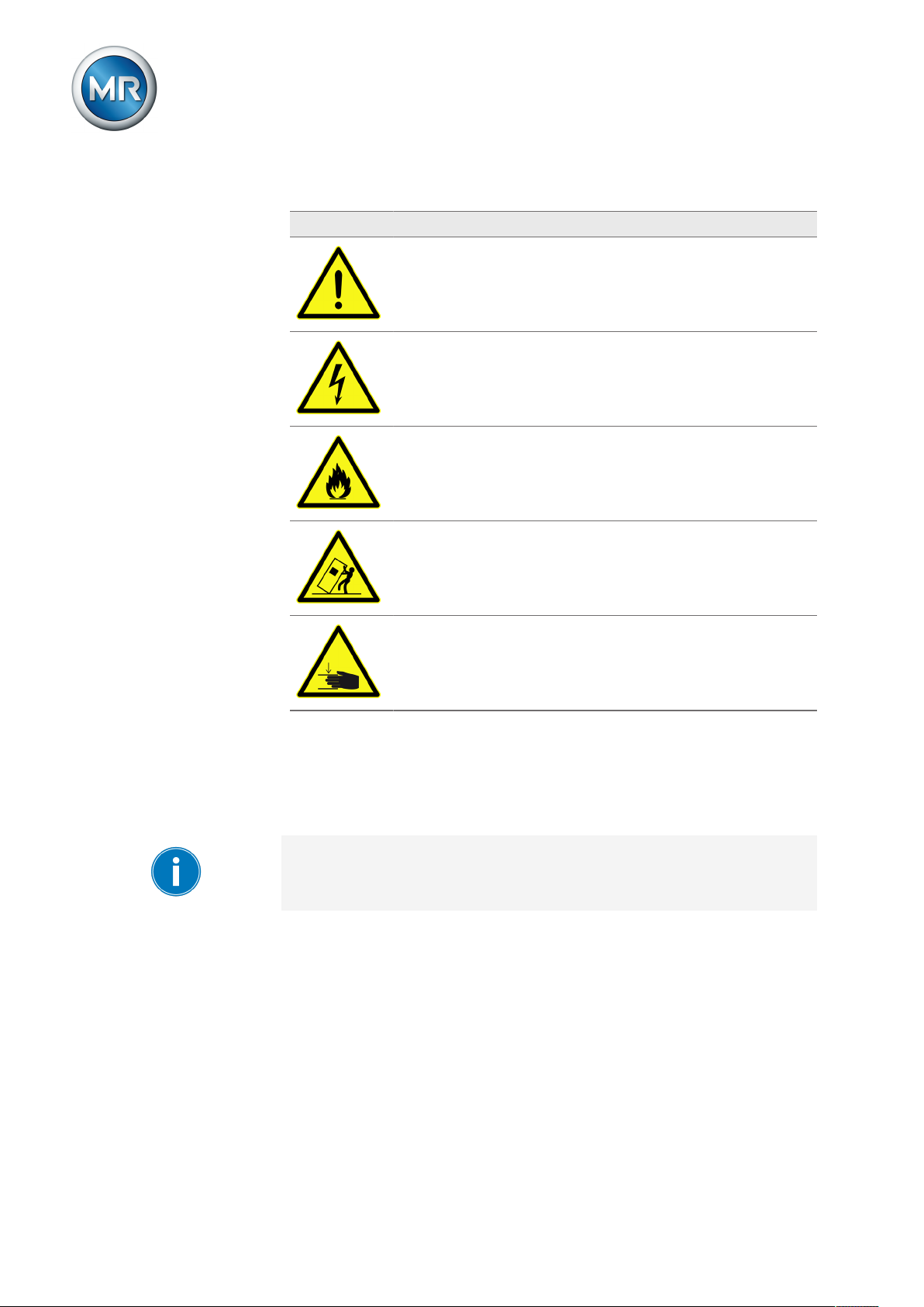
Pictograms warn of dangers:
Pictogram Definition
Warning of a danger point
Warning of dangerous electrical voltage
Warning of combustible substances
Warning of danger of tipping
1 Introduction
Warning of danger of crushing
Table2: Pictograms used in warning notices
1.4.2 Information system
Information is designed to simplify and improve understanding of particular
procedures. In this technical file it is laid out as follows:
Important information.
1.4.3 Instruction system
This technical file contains single-step and multi-step instructions.
Single-step instructions
Instructions which consist of only a single process step are structured as follows:
®
Maschinenfabrik Reinhausen GmbH 20198 6107891/02 ENECOTAP® VPD
Page 9

1 Introduction
Aim of action
ü Requirements (optional).
► Step 1 of 1.
ð Result of step (optional).
ð Result of action (optional).
Multi-step instructions
Instructions which consist of several process steps are structured as follows:
Aim of action
ü Requirements (optional).
1. Step 1.
ð Result of step (optional).
2. Step 2.
ð Result of step (optional).
ð Result of action (optional).
1.4.4 Typographic conventions
The following typographic conventions are used in this technical file:
Typographic convention
UPPERCASE Operating controls, keys AVR MANUAL
Bold Displays/menus P21
Italics System messages/LED dis-
[► Page number]. Cross reference [► 41].
Table3: Typographic conventions
Purpose Example
plays
ERROR LED
Maschinenfabrik Reinhausen GmbH 2019 96107891/02 EN ECOTAP® VPD
®
Page 10

2 Safety
This technical file contains detailed descriptions on the safe and proper installation, connection, commissioning and monitoring of the product.
▪ Read this technical file through carefully to familiarize yourself with the
product.
▪ This technical file is a part of the product.
▪ Read and observe the safety instructions provided in this chapter in partic-
ular.
▪ Observe the warnings in this technical file in order to avoid function-re-
lated dangers.
▪ The product is manufactured on the basis of state-of-the-art technology.
Nevertheless, risks to life and limb for the user or impairment of the product and other material assets may arise in the event of improper use.
2.1 Appropriate use
2 Safety
The product is an on-load tap-changer and adjusts the transmission ratio of
transformers without interrupting the load flow. The product is designed
solely for use in electrical energy systems and facilities. If used as intended
and in compliance with the requirements and conditions specified in this
technical file as well as the warning notices in this technical file and attached
to the product, then the product does not present any danger to people,
property or the environment. This applies throughout service life of the product, from delivery to installation and operation through to disassembly and
disposal.
The following is considered appropriate use:
▪ Only use the ECOTAP®VPD® on-load tap-changer in systems set up in
accordance with IEC61936-1.
▪ You will find the standard valid for the product and the year of issue on the
nameplate.
▪ Only operate the product in accordance with this technical file and the
agreed delivery conditions and technical data.
▪ Only operate standard design on-load tap-changers in entirely oil-filled
transformers. Use in transformers with a gas cushion below the transformer cover is only permitted with an appropriate special design. In such
cases, ensure that the minimum oil fill level stated on the dimensional
drawing supplied is observed.
▪ Operation with alternative insulating fluids is possible in accordance with
the specification in the Technical data [►Section 11, Page 64]. In such
cases, you must ensure compliance with the limited temperature ranges
by means of temperature blocking.
▪ Only operate the ECOTAP®VPD® on-load tap-changer and
ECOTAP®VPD®MD&C motor-drive unit in this combination. Operation
with another on-load tap-changer or motor-drive unit is not permitted.
®
Maschinenfabrik Reinhausen GmbH 201910 6107891/02 ENECOTAP® VPD
Page 11

2 Safety
▪ Ensure that all necessary work is performed by qualified personnel only.
▪ Use the equipment and special tools supplied solely for the intended pur-
pose and in accordance with the specifications of this technical file.
Permitted electrical operating conditions
In addition to the design data in accordance with the order confirmation, observe the following limits for the through-current and the step voltage:
In the standard version, the on-load tap-changer is designed for sinusoidal
50/60 Hz AC current with a curve form symmetrical to the zero axis and can
switch twice the rated through-current Ir at its rated step voltage Uir.
Exceeding the rated step voltage Uir for a short period by up to 10% is permitted if the rated through-current Ir is not exceeded.
2.2 Inappropriate use
Use is considered inappropriate if the product is used in a way other than as
described in the "Appropriate use" section. In addition, observe the following:
Prohibited electrical operating conditions
All operating conditions that do not comply with the design data in accordance with the order confirmation are prohibited.
Prohibited operating conditions may arise due to short circuits as well as due
to inrush current impulses when energizing transformers or other electrical
machines. This applies to the affected transformer itself just as it does to
transformers electrically connected in parallel or serially or other electrical
machines.
Higher voltages may occur due to transformer overexcitation following load
shedding, for example.
Operations outside of the permitted operating conditions can lead to injury to
persons and damage to the product.
▪ Prevent any such operations outside of the permitted operating conditions
by taking suitable measures.
2.3 Fundamental Safety Instructions
To prevent accidents, disruptions and damage as well as unacceptable adverse effects on the environment, those responsible for transport, installation, operation, maintenance and disposal of the product or parts of the product must ensure the following:
Maschinenfabrik Reinhausen GmbH 2019 116107891/02 EN ECOTAP® VPD
®
Page 12

2 Safety
Personal protective equipment
Loosely worn or unsuitable clothing increases the danger of becoming
trapped or caught up in rotating parts and the danger of getting caught on
protruding parts. This increases the danger to life and limb.
▪ All necessary devices and personal protective equipment required for the
specific task, such as a hard hat, safety footwear, etc. must be worn. Observe the section "Personal protective equipment" [►Section 2.5, Page
14].
▪ Never wear damaged personal protective equipment.
▪ Never wear rings, necklaces, or other jewelry.
▪ If you have long hair, wear a hairnet.
Work area
Untidy and poorly lit work areas can lead to accidents.
▪ Keep the work area clean and tidy.
▪ Make sure that the work area is well lit.
▪ Observe the applicable laws for accident prevention in the relevant coun-
try.
Working during operation
The product may only be operated in a sound, operational condition. Otherwise it poses a danger to life and limb.
▪ Regularly check the operational reliability of safety equipment.
▪ Comply with the inspection work, maintenance work and maintenance in-
tervals described in this technical file.
Working with current transformers
Dangerous high voltages may occur when a current transformer is operated
with an open secondary circuit. This can lead to injuries and property damage.
▪ Never operate a current transformer with an open secondary circuit; short-
circuit the current transformer to prevent this.
▪ Observe the information in the current transformer operating instructions.
Explosion protection
Highly flammable or explosive gases, vapors and dusts can cause serious
explosions and fire.
▪ Do not install or operate the product in areas where a risk of explosion is
present.
®
Maschinenfabrik Reinhausen GmbH 201912 6107891/02 ENECOTAP® VPD
Page 13

2 Safety
Safety markings
Warning signs and safety information plates are safety markings on the
product. They are an important aspect of the safety concept.
▪ Observe all safety markings on the product.
▪ Make sure all safety markings on the product remain intact and legible.
▪ Replace safety markings that are damaged or missing.
Ambient conditions
To ensure reliable and safe operation, the product must only be operated
under the ambient conditions specified in the technical data.
▪ Observe the specified operating conditions and requirements for the in-
stallation location.
Modifications and conversions
Unauthorized or inappropriate changes to the product may lead to personal
injury, material damage and operational faults.
▪ Only modify the product after consultation with the manufacturer.
Spare parts
Spare parts not approved by the manufacturer may lead to physical injury,
damage to the product and operational faults.
▪ Only use spare parts approved by the manufacturer.
▪ Contact the manufacturer.
2.4 Personnel qualification
The person responsible for assembly, commissioning, operation, maintenance and inspection must ensure that the personnel are sufficiently qualified.
Electrically skilled person
The electrically skilled person has a technical qualification and therefore has
the required knowledge and experience, and is also conversant with the applicable standards and regulations. The electrically skilled person is also proficient in the following:
▪ Can identify potential dangers independently and is able to avoid them.
▪ Is able to perform work on electrical systems.
▪ Is specially trained for the working environment in which (s)he works.
▪ Must satisfy the requirements of the applicable statutory regulations for
accident prevention.
Maschinenfabrik Reinhausen GmbH 2019 136107891/02 EN ECOTAP® VPD
®
Page 14

2 Safety
Electrically trained persons
An electrically trained person receives instruction and guidance from an
electrically skilled person in relation to the tasks undertaken and the potential dangers in the event of inappropriate handling as well as the protective
devices and safety measures. The electrically trained person works exclusively under the guidance and supervision of an electrically skilled person.
Operator
The operator uses and operates the product in line with this technical file.
The operating company provides the operator with instruction and training
on the specific tasks and the associated potential dangers arising from improper handling.
Technical Service
We strongly recommend having maintenance, repairs and retrofitting carried
out by our Technical Service department. This ensures that all work is performed correctly. If maintenance is not carried out by our Technical Service
department, please ensure that the personnel who carry out the maintenance are trained and authorized by Maschinenfabrik Reinhausen GmbH to
carry out the work.
Authorized personnel
Authorized personnel are trained by Maschinenfabrik Reinhausen GmbH to
carry out special maintenance.
2.5 Personal protective equipment
Personal protective equipment must be worn during work to minimize risks to
health.
▪ Always wear the personal protective equipment required for the job at
hand.
▪ Never wear damaged personal protective equipment.
▪ Observe information about personal protective equipment provided in the
work area.
®
Maschinenfabrik Reinhausen GmbH 201914 6107891/02 ENECOTAP® VPD
Page 15
2 Safety
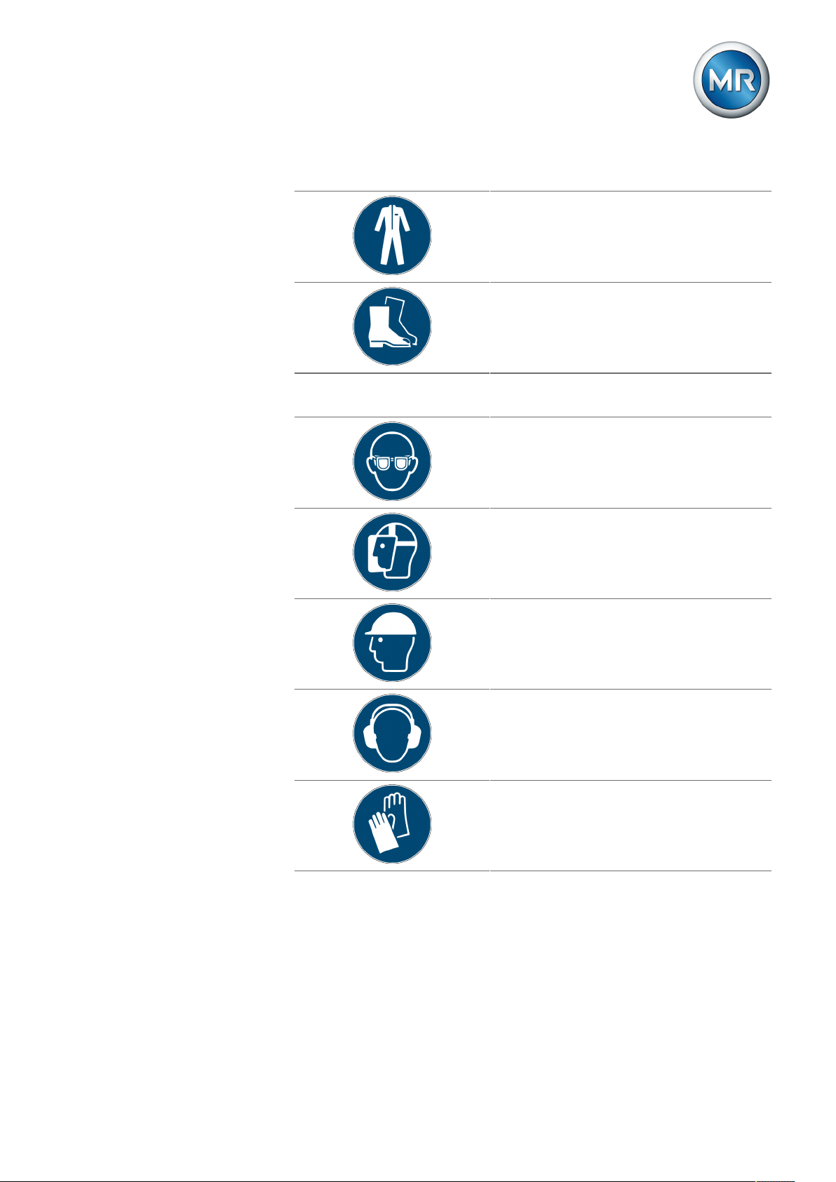
Personal protective equipment to be worn at all times
Protective clothing
Close-fitting work clothing with a low tearing
strength, with tight sleeves and with no protruding parts. It mainly serves to protect the wearer
against being caught by moving machine parts.
Safety shoes
To protect against falling heavy objects and slipping on slippery surfaces.
Special personal protective equipment for particular environments
Safety glasses
To protect the eyes from flying parts and splashing liquids.
Visor
To protect the face from flying parts and splashing liquids or other dangerous substances.
Hard hat
To protect from falling and flying parts and materials.
Hearing protection
To protect from hearing damage.
Protective gloves
To protect from mechanical, thermal, and electrical hazards.
Maschinenfabrik Reinhausen GmbH 2019 156107891/02 EN ECOTAP® VPD
®
Page 16

3 Product description
3 Product description
This chapter contains an overview of the design and function of the product.
3.1 Scope of delivery
The product is packaged with protection against moisture and is delivered as
follows:
▪ On-load tap-changer
▪ Gasket
▪ Fixing screws with locking washers
▪ Nameplate (label)
▪ Technical files
Attach the on-load tap-changer nameplate to the corresponding motor-drive
unit. The position can be found in the section "Design/versions" [►Section
3.4, Page 17].
The crimp sleeves that may be needed for the connection are not included
in the scope of delivery.
Note the following information:
▪ Check the shipment for completeness on the basis of the shipping docu-
ments.
▪ Store the parts in a dry place until installation
▪ The product must remain in its airtight, protective wrapping and may only
be removed immediately before installation
You will find more information in the "Packaging, transport, and storage" [►Section 4, Page 24] chapter.
3.2 Function description
On-load tap-changers are used to adjust the desired tap of a tap winding under load.
The on-load tap-changer is based on the high-speed resistor-type tapchanger principle and uses vacuum cells to change the tap position under
load. In this process, the arc is extinguished while isolated in a vacuum cell,
preventing contaminants from entering the oil.
®
Maschinenfabrik Reinhausen GmbH 201916 6107891/02 ENECOTAP® VPD
Page 17

3 Product description
3.3 Variants
The ECOTAP®VPD® is available as a 3-phase or 1-phase version.
Type ECOTAP®VPD®III ECOTAP®VPD®I
Maximum rated through-current
I
rm
Highest voltage for equipment
U
m
Optional change-over selector Yes No
Table4: ECOTAP® VPD® versions
In the 1-phase version, the connection contacts are arranged on the left or
right side, depending on the order. Figures illustrating this can be found in
the section "ECOTAP® VPD® I without change-over selector" [►Section
3.4.3, Page 21].
For the correct connection, observe the order-specific connection diagram
supplied.
30A
100A
36kV
40.5kV
30A
100A
36kV
More important information can be found in the "Technical data" [►Section
11, Page 64] chapter.
3.4 Setup/models
The design and designation of the most important on-load tap-changer components are shown in the following illustrations. Further details can be found
in the dimensional drawings in the appendix.
Maschinenfabrik Reinhausen GmbH 2019 176107891/02 EN ECOTAP® VPD
®
Page 18
3 Product description
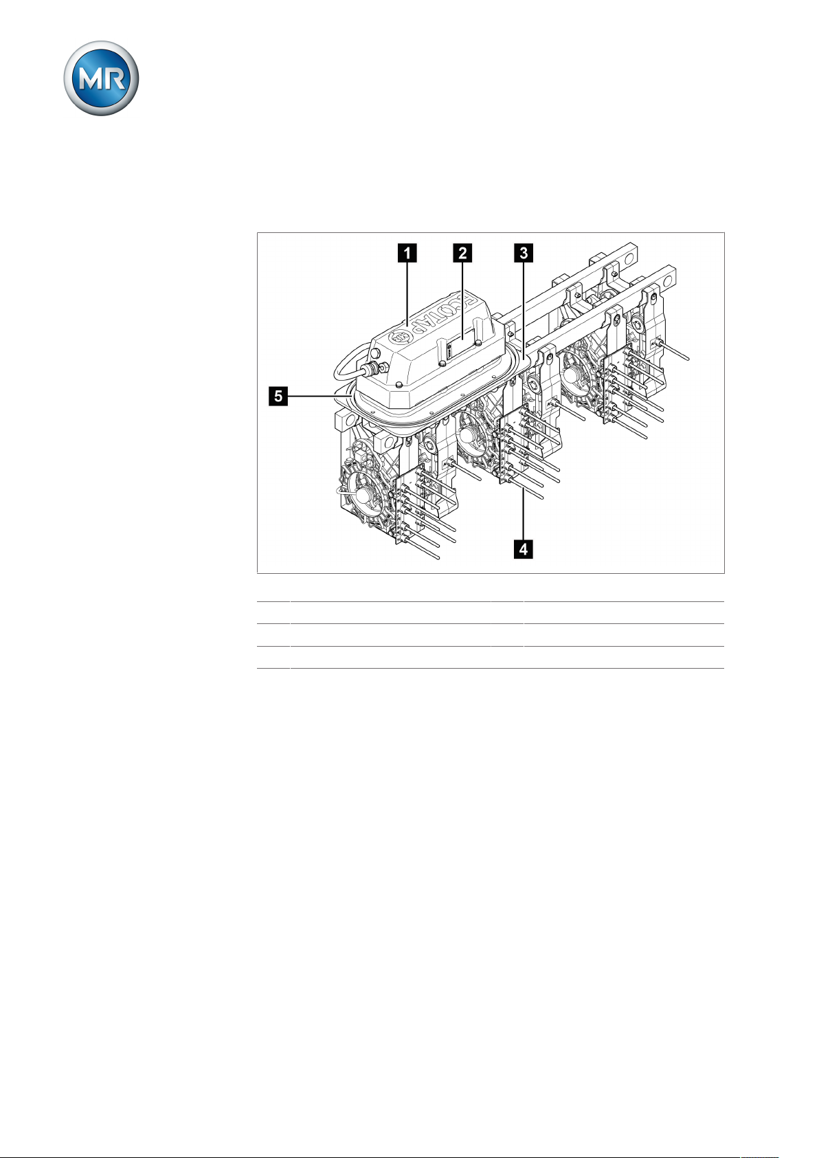
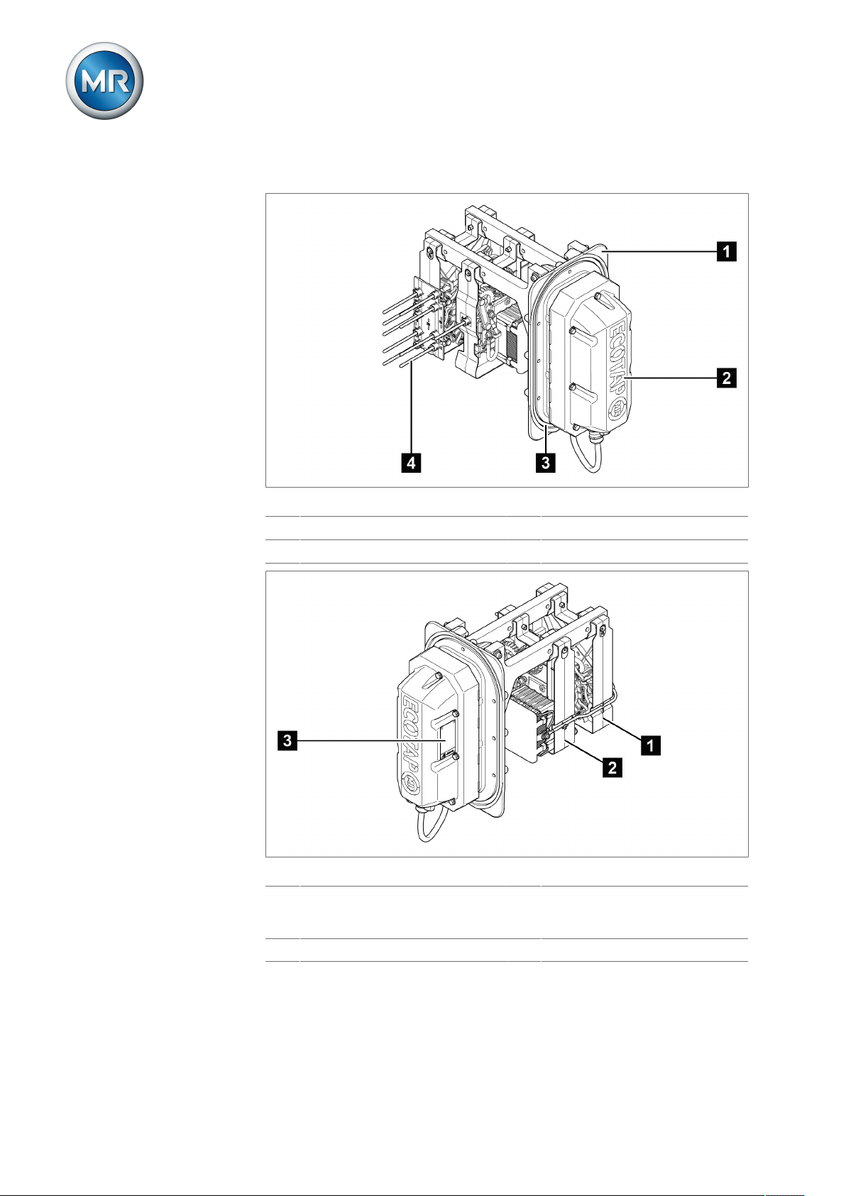
3.4.1 ECOTAP® VPD® III without change-over selector
The on-load tap-changer without change-over selector has 9 operating positions.
Figure1: Front view of the ECOTAP® VPD® without change-over selector
1 Motor-drive unit 2 Nameplate
3 Sealing module 4 Connection contact
5 O-ring gasket
®
Maschinenfabrik Reinhausen GmbH 201918 6107891/02 ENECOTAP® VPD
Page 19
3 Product description
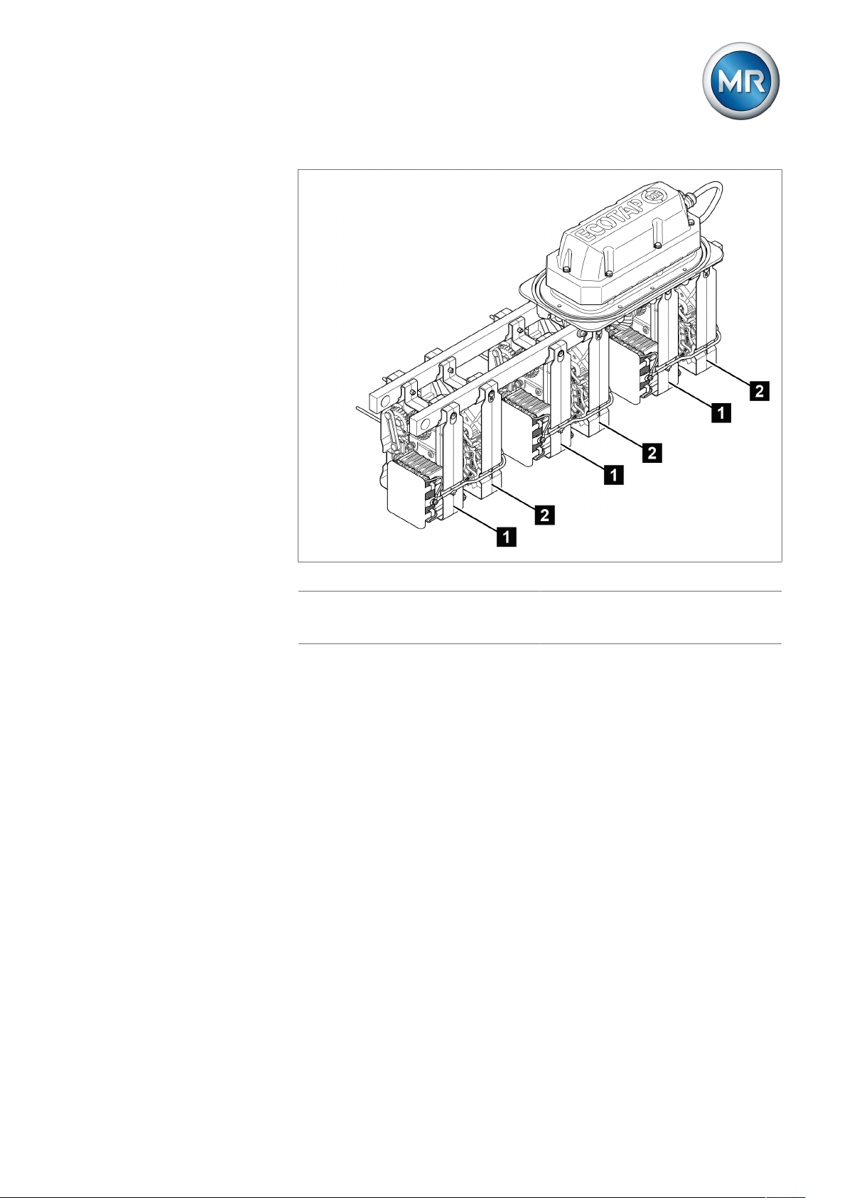
Figure2: Rear view of the ECOTAP® VPD® without change-over selector
1 Diverter switch assembly with tran-
2 Selector assembly
sition resistor and vacuum interrupter
Maschinenfabrik Reinhausen GmbH 2019 196107891/02 EN ECOTAP® VPD
®
Page 20
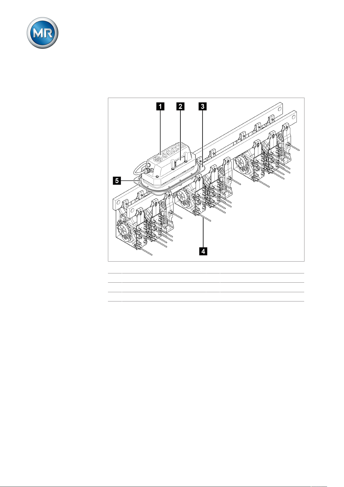
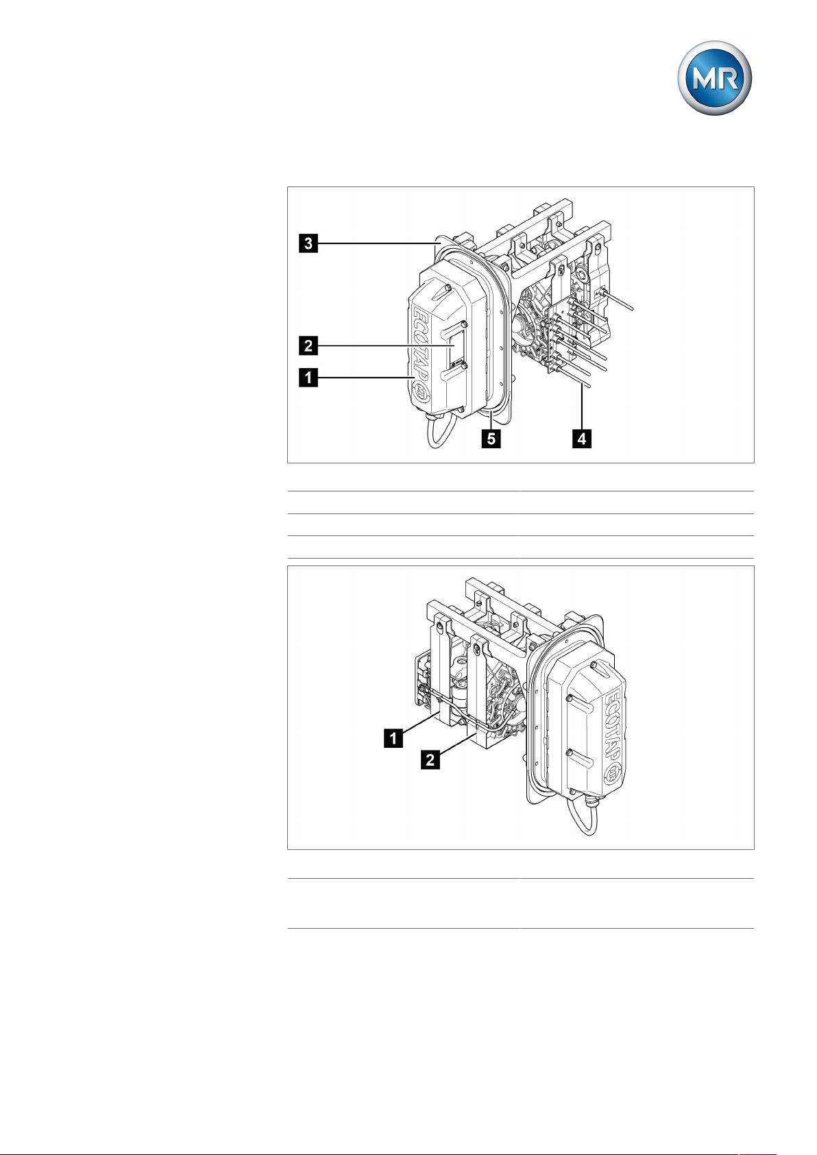
3.4.2 ECOTAP® VPD® III with change-over selector
The on-load tap-changer with change-over selector has 17 operating positions.
3 Product description
Figure3: Front view of the ECOTAP® VPD® with change-over selector
1 Motor-drive unit 2 Nameplate
3 Sealing module 4 Connection contact
5 O-ring gasket
®
Maschinenfabrik Reinhausen GmbH 201920 6107891/02 ENECOTAP® VPD
Page 21
3 Product description
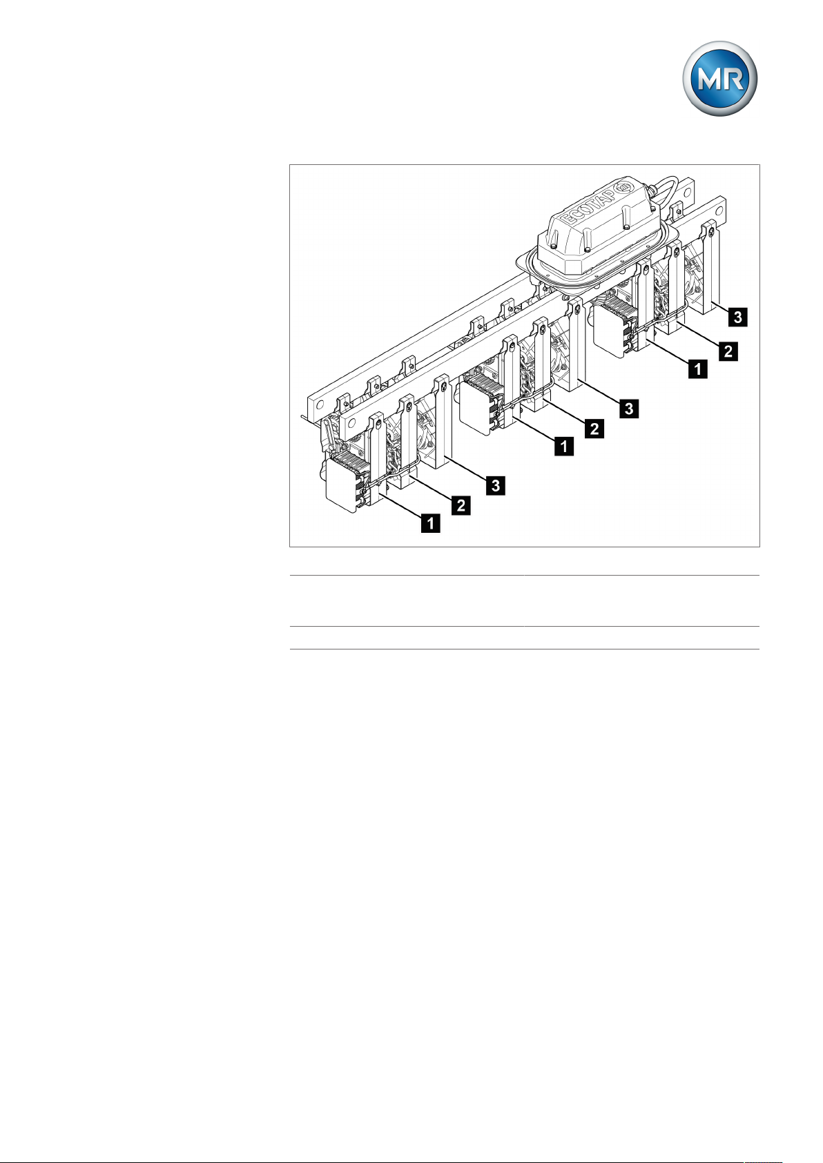
Figure4: Rear view of the ECOTAP® VPD® with change-over selector
1 Diverter switch assembly with tran-
2 Selector assembly
sition resistor and vacuum interrupter
3 Change-over selector assembly
3.4.3 ECOTAP® VPD® I without change-over selector
The 1-phase on-load tap-changer is only available without a change-over selector and has 9 operating positions.
Maschinenfabrik Reinhausen GmbH 2019 216107891/02 EN ECOTAP® VPD
®
Page 22
3 Product description
1-phase on-load tap-changer with connection contacts on the left
Figure5: Front view, ECOTAP® VPD® I, connection contacts on left
1 Sealing module 2 Motor-drive unit
3 O-ring gasket 4 Connection contact
Figure6: Rear view, ECOTAP® VPD® I, connection contacts on left
1 Selector assembly 2 Diverter switch assembly with tran-
sition resistor and vacuum interrupter
3 Nameplate
®
Maschinenfabrik Reinhausen GmbH 201922 6107891/02 ENECOTAP® VPD
Page 23
3 Product description
1-phase on-load tap-changer with connection contacts on the right
Figure7: Front view, ECOTAP® VPD® I, connection contacts on right
1 Motor-drive unit 2 Nameplate
3 Sealing module 4 Connection contact
5 O-ring gasket
Figure8: Rear view, ECOTAP® VPD® I, connection contacts on right
1 Diverter switch assembly with tran-
2 Selector assembly
sition resistor and vacuum interrupter
Maschinenfabrik Reinhausen GmbH 2019 236107891/02 EN ECOTAP® VPD
®
Page 24

4 Packaging, transport and storage
4 Packaging, transport and storage
4.1 Packaging
The products are sometimes supplied with sealed packaging and sometimes
in a dry state, depending on requirements.
Sealed packaging surrounds the packaged goods with plastic foil on all
sides.
Products that have also been dried are identified by a yellow label on the
sealed packaging. In the dry state, delivery is also possible in a transport
container.
The information in the following sections should be applied as appropriate.
4.1.1 Suitability
NOTICE
Property damage due to incorrectly stacked crates!
Stacking the crates incorrectly can lead to damage to the packaged goods.
► The outer marking on the packaging states if, for example, the on-load
tap-changer or selector has been packed upright. Never stack these
crates.
► General rule: Do not stack crates above a height of 1.5 m.
► For other crates: Only stack up to 2 equally sized crates on top of one an-
other.
The packaging is suitable to ensure undamaged and fully functional means
of transportation in compliance with local transportation laws and regulations.
The packaged goods are packed in a sturdy crate. This crate ensures that,
when in the intended transportation position, the packaged goods are stabilized to prevent impermissible changes in position, and that none of the parts
touch the loading surface of the means of transport or touch the ground after
unloading.
Sealed packaging surrounds the packaged goods with plastic foil on all
sides. The packaged goods are protected from humidity using a desiccant.
The plastic foil was bonded after the desiccant is added.
®
Maschinenfabrik Reinhausen GmbH 201924 6107891/02 ENECOTAP® VPD
Page 25
4 Packaging, transport and storage
4.1.2 Markings
The packaging bears a signature with instructions for safe transport and correct storage. The following symbols apply to the shipment of non-hazardous
goods. Adherence to these symbols is mandatory.
WARNING
Protect against
moisture
Table5: Shipping pictograms
Top Fragile Attach lifting
gear here
Center of mass
4.2 Transportation, receipt and handling of shipments
Danger of death and damage to property!
Danger of death and damage to property due to tipping or falling load.
► Only transport the crate when closed.
► Do not remove the securing material used in the crate during transport.
► If the product is delivered on a pallet, secure it sufficiently.
► Only trained and authorized persons may select the sling gear and se-
cure the load.
► Do not walk under the hanging load.
► Use means of transport and lifting gear with a sufficient carrying capacity
in accordance with the weight stated on the delivery slip.
In addition to oscillation stress, jolts must also be expected during transportation. In order to prevent possible damage, avoid dropping, tipping,
knocking over and colliding with the product.
If a crate tips over, falls from a certain height (e.g. when slings tear) or is
subject to an unbroken fall, damage must be expected regardless of the
weight.
Every delivered shipment must be checked for the following by the recipient
before acceptance (acknowledgment of receipt):
▪ Completeness based on the delivery slip
▪ External damage of any type
The checks must take place after unloading when the crate or transport container can be accessed from all sides.
Maschinenfabrik Reinhausen GmbH 2019 256107891/02 EN ECOTAP® VPD
®
Page 26

4 Packaging, transport and storage
Visible damage If external transport damage is found upon receipt of the shipment, proceed
as follows:
▪ Immediately record the identified transport damage in the shipping docu-
ments and have this countersigned by the carrier.
▪ In the event of severe damage, total loss or high damage costs, immedi-
ately notify the manufacturer and the relevant insurance company.
▪ After identifying damage, do not modify the condition of the shipment fur-
ther and retain the packaging material until an inspection decision has
been made by the transport company or the insurance company.
▪ Record the details of the damage immediately on site together with the
carrier involved. This is essential for any claim for damages.
▪ Photograph damage to packaging and packaged goods. This also applies
to signs of corrosion on the packaged goods due to moisture inside the
packaging (rain, snow, condensation).
▪ NOTICE! If the product is delivered in sealed packaging, inspect this im-
mediately. If the sealed packaging is damaged, do not under any circumstances install or commission the packaged goods. Either re-dry the dried
packaged goods as per the operating instructions, or contact the manufacturer to agree on how to proceed. Failure to do so may result in damage to the packaged goods.
▪ Identify the damaged parts.
Hidden damage When damages are not determined until unpacking after receipt of the ship-
ment (hidden damage), proceed as follows:
▪ Make the party responsible for the damage liable as soon as possible by
telephone and in writing, and prepare a damage report.
▪ Observe the time periods applicable to such actions in the respective
country. Inquire about these in good time.
With hidden damage, it is very hard to make the transportation company (or
other responsible party) liable. Any insurance claims for such damages can
only be successful if relevant provisions are expressly included in the insurance terms and conditions.
4.3 Storage of shipments
Packaged goods dried by Maschinenfabrik Reinhausen
Upon receipt of the shipment, immediately remove the packaged goods
dried by Maschinenfabrik Reinhausen from the sealed packaging and store
air-tight in dry insulating oil until used if the packaged goods were not supplied in oil.
Non-dried packaged goods
Non-dried packaged goods but with a functional sealed packaging can be
stored outdoors when the following conditions are complied with.
®
Maschinenfabrik Reinhausen GmbH 201926 6107891/02 ENECOTAP® VPD
Page 27

4 Packaging, transport and storage
When selecting and setting up the storage location, ensure the following:
▪ Protect stored goods against moisture (flooding, water from melting snow
and ice), dirt, pests such as rats, mice, termites and so on, and against
unauthorized access.
▪ Store the crates on timber beams and planks as a protection against ris-
ing damp and for better ventilation.
▪ Ensure sufficient carrying capacity of the ground.
▪ Keep entrance paths free.
▪ Check stored goods at regular intervals. Also take appropriate action after
storms, heavy rain or snow and so on.
Protect the packaging foil from direct sunlight so that it does not disintegrate
under the influence of UV rays, which would cause the packaging to lose its
sealing function.
If the product is installed more than 6 months after delivery, suitable measures must be taken without delay. The following measures can be used:
▪ Correctly regenerate the drying agent and restore the sealed packaging.
▪ Unpack the packed goods and store in a suitable storage space (well ven-
tilated, as dust-free as possible, humidity < 50% where possible).
4.4 Unpacking shipments and checking for transportation
damages
▪ NOTICE! Transport the packaged crate to the place where installation will
take place. Do not open the sealed packaging until just before installation.
If this is not done, damage to the packaged goods may occur due to ineffectively sealed packaging.
▪ WARNING! When unpacking, check the condition of the packaged
goods.Secure packaged goods in an upright crate from tipping out. If this
is not done, the packaged goods may be damaged and serious injuries
may result.
▪ Check completeness of supplementary parts on the basis of the delivery
slip.
Maschinenfabrik Reinhausen GmbH 2019 276107891/02 EN ECOTAP® VPD
®
Page 28

5 Mounting
5 Mounting
5.1 Fastening on-load tap-changer to transformer cover
NOTICE
Damage to the on-load tap-changer and transformer!
Damage to on-load tap-changer and transformer due to electrical flashover
caused by insufficient distance from the motor-drive unit!
► When positioning the opening in the transformer, ensure a sufficient dis-
tance from adjacent energized parts.
Mount the on-load tap-changer horizontally with the sealing module on the
transformer cover.
Do not paint the surface on the underside of the transformer cover, which
later makes contact with the sealing module's o-ring. Only one coating of
primer is permitted.
1. Make opening for sealing module and holes for fixing screws in the transformer cover. The measurements and position can be found in the dimensional drawing in the appendix.
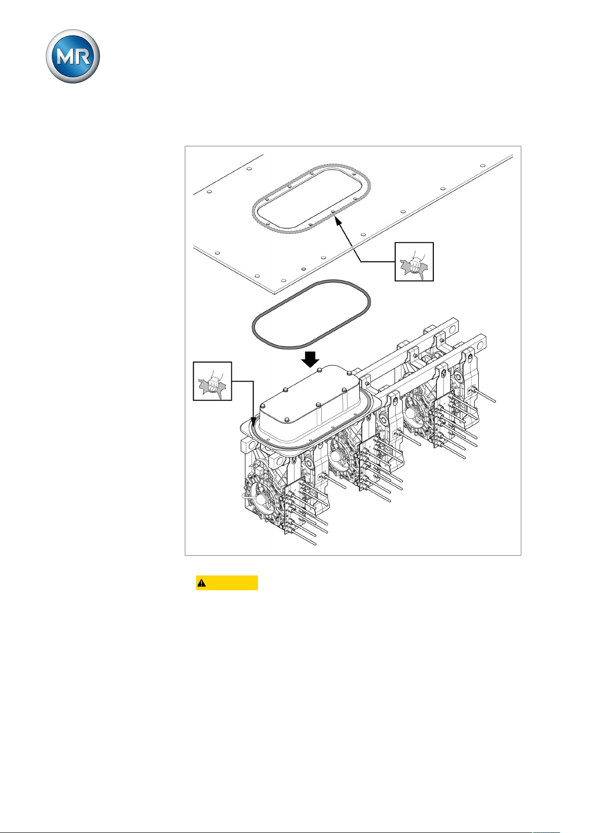
2. Clean sealing surfaces on sealing module and underside of transformer
cover. Insert O-ring supplied in sealing module.
3. CAUTION! Gradually tighten screws crosswise as described below
without warping or deforming. Improper screw connection will result in
damage to the on-load tap-changer.
4. Guide on-load tap-changer from below through the opening in the transformer cover.
5. Evenly tighten screws crosswise by hand. Tighten screws crosswise with
a pre-tightening torque of 9 Nm.
6. Check seat of flange and seal for regularity.
7. Tighten screws crosswise with the full tightening torque of 16 Nm.
8. Tighten screws again with full tightening torque, working clockwise and
tightening one screw after another as far as each screw will go.
NOTICE
5.1.1 Attaching the ECOTAP® VPD® III
Damage to the on-load tap-changer and transformer!
The on-load tap-changer may only be operated in transformers that are
completely filled with insulating fluid. Non-compliance may result in voltage
flashovers that cause serious damage to the on-load tap-changer and transformer.
► Use in hermetic transformers with a gas cushion below the transformer
cover is only permitted with an appropriate special design.
®
Maschinenfabrik Reinhausen GmbH 201928 6107891/02 ENECOTAP® VPD
Page 29
5 Mounting
Mount the on-load tap-changer horizontally with the sealing module on the
transformer cover.
Do not paint the surface on the underside of the transformer cover, which
later makes contact with the sealing module's o-ring. Only one coating of
primer is permitted.
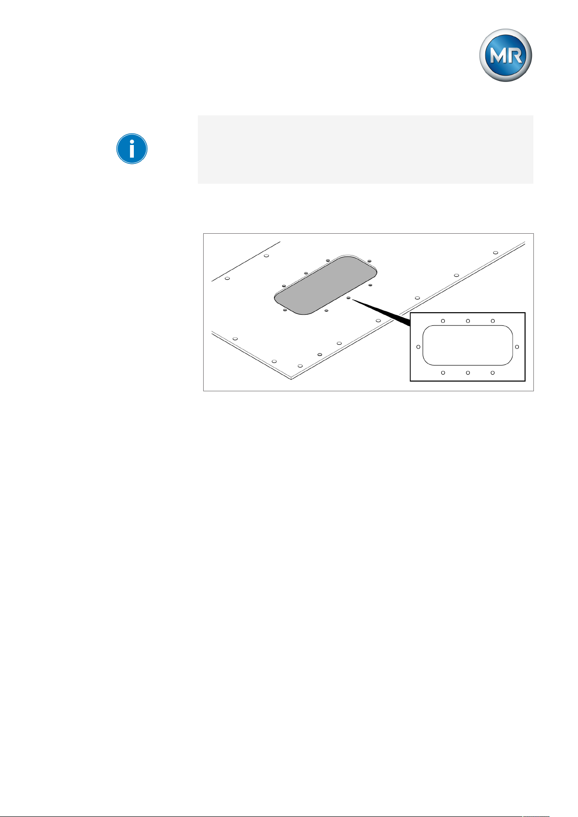
1. Make opening for sealing module and holes for fixing screws in the transformer cover. The measurements and position can be found in the dimensional drawing in the appendix.
Figure9: Top view of transformer cover with opening for sealing module
Maschinenfabrik Reinhausen GmbH 2019 296107891/02 EN ECOTAP® VPD
®
Page 30
5 Mounting
2. Clean sealing surfaces on sealing module and underside of transformer
cover. Insert O-ring supplied in sealing module.
Figure10: O-ring gasket
3. CAUTION! Gradually tighten screws crosswise as described below
without warping or deforming. Improper screw connection will result in
damage to the on-load tap-changer.
4. Guide on-load tap-changer from below through the opening in the transformer cover.
5. Evenly tighten screws crosswise by hand. Tighten screws crosswise with
a pre-tightening torque of 9 Nm.
6. Check seat of flange and seal for regularity.
®
Maschinenfabrik Reinhausen GmbH 201930 6107891/02 ENECOTAP® VPD
Page 31

5 Mounting
7. Tighten screws crosswise with the full tightening torque of 16 Nm.
Figure11: Fastening the on-load tap-changer
Pre-tightening torque 9 Nm
Full tightening torque 16 Nm
8. Tighten screws again with full tightening torque, working clockwise and
tightening one screw after another as far as each screw will go.
Maschinenfabrik Reinhausen GmbH 2019 316107891/02 EN ECOTAP® VPD
®
Page 32

5.1.2 Attaching the ECOTAP® VPD® I
5 Mounting
NOTICE
Damage to the on-load tap-changer and transformer!
The on-load tap-changer must be fully immersed in insulating fluid. Energized parts of the on-load tap-changer coming into contact with air may result in voltage flashovers that cause serious damage to the on-load tapchanger and transformer.
► Use in hermetic transformers with a gas cushion is only permitted if there
is sufficient distance between the gas cushion and the on-load tapchanger and connection contacts.
► The distance to the gas cushion must ensure that the on-load tap-
changer is fully immersed in insulating fluid in every operating situation.
Mount the on-load tap-changer vertically with the sealing module on the
transformer side wall.
Do not paint the inner surface of the transformer side wall which will later
make contact with the sealing module o-ring. Only one coating of primer is
permitted.
1. Make an opening for the sealing module and holes for the fixing screws
on the transformer side wall. The measurements and position can be
found in the dimensional drawing in the appendix.
Figure12: View of the transformer side wall with opening for sealing module
®
Maschinenfabrik Reinhausen GmbH 201932 6107891/02 ENECOTAP® VPD
Page 33

5 Mounting
2. Clean the sealing surfaces on the sealing module and the transformer
side wall. Insert O-ring supplied in sealing module.
Figure13: O-ring gasket
3. CAUTION! Gradually tighten screws crosswise as described below
without warping or deforming. Improper screw connection will result in
damage to the on-load tap-changer.
4. Lead the on-load tap-changer sideways from the inside through the opening in the transformer side wall.
5. Evenly tighten screws crosswise by hand. Tighten screws crosswise with
a pre-tightening torque of 9 Nm.
6. Check seat of flange and seal for regularity.
Maschinenfabrik Reinhausen GmbH 2019 336107891/02 EN ECOTAP® VPD
®
Page 34

5 Mounting
7. Tighten screws crosswise with the full tightening torque of 16 Nm.
Figure14: Fastening the on-load tap-changer
Pre-tightening torque 9 Nm
Full tightening torque 16 Nm
8. Tighten screws again with full tightening torque, working clockwise and
tightening one screw after another as far as each screw will go.
®
Maschinenfabrik Reinhausen GmbH 201934 6107891/02 ENECOTAP® VPD
Page 35

5 Mounting
5.2 Connecting tap winding and on-load tap-changer take-off
lead
NOTICE
Damage to the on-load tap-changer caused by improper mounting!
Mounting mistakes will damage the on-load tap-changer and jeopardize
safe operation.
► Connect connecting leads without warping or deforming them and ensure
that no forces are transferred from the connecting leads to the on-load
tap-changer.
► Place at least 3mm of paper insulation on the connecting leads – includ-
ing connection points – that face the transformer cover or the transformer
side wall to ensure the dielectric strength.
► Bending the connection contacts may limit the dielectric strength in accor-
dance with the specification in the "Technical data" [►Section 11.4, Page
69] chapter and reduce the rated withstand voltages! Ensure that the dielectric strength needed for the application is still ensured after assembly.
► The diagram below shows the areas particularly critical for insulation
spacing. Avoid bending the connection contacts into these critical areas.
ECOTAP® VPD® III on-load tap-changer without change-over selector
Figure15: Insulation spacing for ECOTAP®VPD® III without change-over selector
1 Transformer cover
2 Critical area: Spacing to grounded parts
3 Critical area: Spacing between the phases
Maschinenfabrik Reinhausen GmbH 2019 356107891/02 EN ECOTAP® VPD
®
Page 36

5 Mounting
ECOTAP® VPD® III on-load tap-changer with change-over selector
Figure16: Insulation spacing for ECOTAP®VPD® III with change-over selector
1 Transformer cover
2 Critical area: Spacing to grounded parts
3 Critical area: Spacing between the phases
®
Maschinenfabrik Reinhausen GmbH 201936 6107891/02 ENECOTAP® VPD
Page 37

5 Mounting
ECOTAP® VPD® I on-load tap-changer without change-over selector
NOTICE
Figure17: Insulation spacing for ECOTAP®VPD® I without change-over selector
1 Transformer side wall
2 Supporting bar
3 Critical area: Spacing to grounded parts
Damage to on-load tap-changer due to improperly carried out
crimp connections!
Improperly carried out crimp connections jeopardize safe operation.
► Carry out crimp connections in accordance with DIN EN 61238-1.
► The connection contacts on crimp connections may be shortened by no
more than 6 cm.
Maschinenfabrik Reinhausen GmbH 2019 376107891/02 EN ECOTAP® VPD
®
Page 38

5 Mounting
NOTICE
Damage to on-load tap-changer due to improperly carried out
solder connections!
Improperly carried out solder connections jeopardize safe operation.
► The connection contacts may not be shortened.
► The solder connection may only be produced on the end of the connec-
tion contacts (approx. 30 mm).
► Depending on the materials used, ensure the correct application of heat
to prevent both cold solder spots and thermal damage to the on-load tapchanger.
► Ensure that sharp edges or points are not produced at the connection
points. These may cause a local concentration of the field strength and
therefore result in partial discharge.
► Remove flux material residue.
Taking these safety notices into consideration, you can establish the connections in accordance with the supplied order-specified connection diagram. This connection diagram also contains the exact assignment of the individual connecting pieces of the on-load tap-changer.
1. To do so, connect the leads for the tap winding and on-load tap-changer
take-off leads to the on-load tap-changer's connection contacts by means
of crimping or soldering, without twisting.
Figure18: Tap winding connection (example for ECOTAP® VPD® III)
®
Maschinenfabrik Reinhausen GmbH 201938 6107891/02 ENECOTAP® VPD
Page 39

5 Mounting
Figure19: Tap winding connection (example for ECOTAP® VPD® I)
2. If the connection contacts have to be bent, observe the aforementioned
safety notices and use additional pliers to hold in place during bending so
that none of the forces are transferred to the on-load tap-changer. For
reasons of accessibility, we recommend starting with the bottom connections.
If you have any questions about producing the connections, please contact
Maschinenfabrik Reinhausen GmbH's Technical Service department.
5.3 Mounting motor-drive unit and control unit
As preparation, you must ensure that the on-load tap-changer is in a defined
operating position.
1. DANGER! Check the operating position before the transformer is
commissioned or ensure that the transformer is disconnected from all voltage sources and secured against reconnection. Failure to do so can lead
to death or serious injuries.
Maschinenfabrik Reinhausen GmbH 2019 396107891/02 EN ECOTAP® VPD
®
Page 40

5 Mounting
2. Remove transport locking plate and store safely. To avoid contamination
and mechanical damage, do not leave the sealing module open for long
periods of time.
Figure20: Removing the transport locking plate
3. When mounting for the first time: remove label with warning.
Figure21: Removing the label
®
Maschinenfabrik Reinhausen GmbH 201940 6107891/02 ENECOTAP® VPD
Page 41

5 Mounting
4. Check the position of the on-load tap-changer: The current operating position is displayed by the control wheel.
Figure22: Checking operating position (exemplary illustration)
5. Check additionally the position of the shaft of the on-load tap-changer: If
the previous on-load tap-change operation has been finished correctly,
the arrow on the cam disk is pointing to the arrow in the cover .
Figure23: Position of the shaft of the on-load tap-changer
ð If the shaft of the on-load tap-changer is in this position, the on-load
tap-changer is in a defined operating position. If this is not the case,
correct the position as described below.
6. NOTICE! Only use the emergency drive shaft installed in the sealing
module. Failure to do so can result in damage to the on-load tap-changer.
Maschinenfabrik Reinhausen GmbH 2019 416107891/02 EN ECOTAP® VPD
®
Page 42

5 Mounting
7. Pull the emergency drive shaft out of the bracket in the sealing module.
Figure24: Removing emergency drive shaft
8. Plug the emergency drive shaft with feather key into the shaft of the onload tap-changer.
Figure25: Attaching emergency drive shaft
9. Rotate emergency drive shaft in direction of desired operating position using an appropriate tool.
Figure26: Emergency drive shaft actuation
®
Maschinenfabrik Reinhausen GmbH 201942 6107891/02 ENECOTAP® VPD
Page 43

5 Mounting
10. NOTICE! Using the emergency drive shaft, turn for every tap-change
operation in one direction until one revolution has been completed and
the arrow on the cam disk (1) is again pointing to the arrow in the cover
(2). Otherwise the tap-change operation is not completed correctly,
which may result in damage to the on-load tap-changer and transformer.
Figure27: Position of the shaft of the on-load tap-changer
ð The current operating position is displayed by the control wheel.
Figure28: Checking operating position (exemplary illustration)
11. Pull the emergency drive shaft out of the shaft of the on-load tapchanger and plug it back into the bracket.
Figure29: Plugging the emergency drive shaft back in
12. Close the sealing module with the transport locking plate if the motordrive unit is not to be mounted immediately.
Maschinenfabrik Reinhausen GmbH 2019 436107891/02 EN ECOTAP® VPD
®
Page 44

5 Mounting
You have to mount and remove the motor-drive unit and control unit several
times:
1. After installing the on-load tap-changer, mount the motor-drive unit and
control unit and start them up, including automatic adjustment and trial
tap-change operations.
This first partial commissioning process is needed for you to be able to
check the wiring between the on-load tap-changer and transformer in accordance with the following description in the "Taking measurements" [►Section 5.4, Page 44] section.
2. Before "Drying the on-load tap-changer" [►Section 5.5, Page 46], remove the motor-drive unit and control unit again to avoid damage.
3. Drying and filling with oil [►Section 5.6, Page 48] is followed by the step
"Commissioning the on-load tap-changer at the transformer manufacturer's site" [►Section 6.1, Page 49]. This involves mounting the motordrive unit and control unit for a second time.
4. Before performing the "dielectric tests on the transformer wiring [►Section
6.1.1.2, Page 51]", disconnect the connection cable to the motor-drive
unit on the control unit to avoid damage.
5. Before "Commissioning the transformer at the operating site" [►Section
6.3, Page 54], reconnect and commission the control unit.
WARNING
NOTICE
You will find the description of how to mount, commission, and test the motor-drive unit and control unit in the operating instructions for the
ECOTAP®VPD®MD&C motor-drive unit.
5.4 Taking measurements
Electric shock from incorrect operation!
Danger of death or severe injury from electric shock!
► Only take measurements when the transformer is de-energized.
► Only perform tap-change operation with the control unit.
► Tap-change operations initiated by actuation with the emergency drive
shaft are not permitted during this test.
Damage to on-load tap-changer and motor-drive unit!
Damage to on-load tap-changer and transformer due to improper transformer ratio test!
► Do not perform more than 100 tap-change operations without a full oil fill.
► Only switch on-load tap-changer with the help of the control unit.
► Only use emergency drive shaft to rectify faults [►Section 8, Page 58]
and never operate with a drill.
Before drying the transformer, undertake the transformer ratio test and DC
resistance measurement as described below.
®
Maschinenfabrik Reinhausen GmbH 201944 6107891/02 ENECOTAP® VPD
Page 45

5 Mounting
This requires the motor-drive unit and control unit to be correctly mounted
and commissioned in accordance with the operating instructions for the
ECOTAP®VPD®MD&C motor-drive unit. These instructions also contain
further details of the trial tap-change operations required, automatic adjustment, and how to operate the control unit.
Carrying out transformer ratio test
1. Press on the control unit to activate manual mode.
ð LED above the key lights up.
Figure30: Activating manual mode
2. Press or until the desired operating position is reached.
ð The new operating position is displayed on the control unit.
3. Carry out the transformer ratio test in all operating positions.
ð Once the results have been checked, the transformer ratio test is com-
plete.
Maschinenfabrik Reinhausen GmbH 2019 456107891/02 EN ECOTAP® VPD
®
Page 46

5 Mounting
Check the transformer configuration in accordance with the supplied connection diagrams if the tap-change operation is not in the desired direction.
The behavior of the control unit (lowest voltage at smallest or largest position) can be adjusted accordingly via parameterization. To do so, follow the
description in the ECOTAP®VPD®MD&C motor-drive unit operating instructions, section "Inverting travel commands".
Carrying out DC resistance measurement
The measured DC current is normally restricted to 10% of the rated current
of the measured transformer winding in order to prevent the winding from
overheating.
Observe the maximum permitted measured currents for the on-load tapchanger during the DC resistance measurement on the transformer.
Maximum permissible measured current
Transformer tank empty Maximum 10 A DC
Transformer tank filled with insulating oil Maximum 10 A DC
Table6: Maximum permissible measured currents
NOTICE
Carry out the DC resistance measurement as follows:
1. Press on the control unit to activate manual mode.
ð LED above the key lights up.
2. Press or until the desired operating position is reached.
ð The new operating position is displayed on the control unit.
3. Carry out the DC resistance measurement in all operating positions.
ð Once the results have been checked, the DC resistance measurement is
complete.
5.5 Drying the on-load tap-changer
Damage to the on-load tap-changer, motor-drive unit, and control unit from drying!
Incorrectly performed drying will damage components sensitive to temperature.
► Remove motor-drive unit and control unit and do not dry.
► Before drying, fit transport locking plate to protect the on-load tap-
changer in accordance with the description below.
► Ensure that the temperature of the on-load tap-changer does not exceed
135 °C.
®
Maschinenfabrik Reinhausen GmbH 201946 6107891/02 ENECOTAP® VPD
Page 47

5 Mounting
To prepare for drying, proceed as follows:
ü Remove motor-drive unit and control unit as described in the section "Dis-
assembly before transformer drying" in the operating instructions for the
ECOTAP®VPD®MD&C motor-drive unit.
1. Clean sealing surfaces on sealing module and transport locking plate and
check that o-ring is in the correct position.
2. Attach and fasten transport locking plate before drying.
Figure31: Fastening transport locking plate
Potential drying methods:
You can dry the on-load tap-changer using one of the following methods.
▪ Vacuum-drying in an autoclave
▪ Vacuum-drying in the transformer tank
▪ Vapor-phase drying in an autoclave
▪ Vapor-phase drying in the transformer tank
▪ Low-frequency drying in an autoclave
▪ Low-frequency drying in a transformer tank
The drying time depends on the transformer.
Maschinenfabrik Reinhausen GmbH 2019 476107891/02 EN ECOTAP® VPD
®
Page 48

5.6 Filling transformer with oil
For the oil filling of the transformer, use new mineral insulating oil for transformers as per IEC60296 (Specification of unused mineral insulating oils for
transformers and switchgear).
If approved by the transformer manufacturer, synthetic ester liquids as per
IEC61099 (Specification for unused synthetic organic esters for electrical
purposes) or natural ester liquids as per IEC62770 (Specification for unused
natural esters for transformers and similar electrical equipment) can be used
as alternatives.
Contact Maschinenfabrik Reinhausen GmbH if you want to use an alternative insulating fluid.
Observe the permitted temperature range of the transformer oil in the "Technical data" [►Section 11.2, Page 65] chapter.
5 Mounting
NOTICE
Damage to the on-load tap-changer!
If a transformer is not completely filled with oil, the on-load tap-changer may
be damaged!
► Before commissioning the on-load tap-changer, completely fill trans-
former with oil.
► If using the special design of the 3-phase on-load tap-changer for her-
metic transformers with gas cushion, be sure to observe the oil fill details
on the supplied dimensional drawing.
1. Completely fill transformer with oil.
2. Take oil sample from transformer.
3. Record temperature of oil sample just after sample is taken.
4. Determine dielectric strength and water content at an oil temperature of
20°C ± 5°C. The dielectric strength and water content must comply with
the limit values stated below:
U
d
When commissioning the
transformer for the first
time
Table7: Limit values for mineral insulating oil (dielectric strength Ud measured in accordance
with IEC60156)
> 60 kV/2.5 mm < 12ppm
H2O
®
Maschinenfabrik Reinhausen GmbH 201948 6107891/02 ENECOTAP® VPD
Page 49

6 Commissioning
6 Commissioning
This chapter describes how to commission the device. Commissioning is
broken down into the following sections:
▪ Commissioning at the transformer manufacturer's site
▪ Transporting transformer to the operating site
▪ Commissioning at the operating site
6.1 Commissioning the on-load tap-changer at the transformer
manufacturer's site
WARNING
NOTICE
Flying parts and spraying of hot oil resulting from on-load tapchanger overload!
The on-load tap-changer can switch currents of up to twice the rated
through-current. Higher currents occur when activating transformers (inrush
current impulse) or in the event of short-circuits, for example. Higher voltages may occur due to transformer overexcitation following load shedding,
for example.
Danger of death or severe injury due to flying parts and spraying of hot oil!
► Ensure that the on-load tap-changer is not overloaded.
► Prevent on-load tap-change operations if higher currents arise.
► Ensure that the rated step voltage is not exceeded. The rated step volt-
age may be briefly exceeded by up to 10% as long as the rated throughcurrent is not exceeded.
► Ensure that the temperature limit values stated in the technical data are
not exceeded.
Damage to on-load tap-changer resulting from switching without oil!
Performing too many operations without a complete transformer oil fill will
damage the on-load tap-changer!
► Do not perform more than 100 tap-change operations without a full oil fill.
► Only use emergency drive shaft to rectify faults [►Section 8, Page 58]
and never operate with a drill.
Before starting to test the transformer, take the following steps, which are
described in detail in the operating instructions for the ECOTAP® VPD® motor-drive unit:
1. Mount and connect motor-drive unit and control unit.
2. Commission motor-drive unit and control unit.
3. Carry out automatic adjustment and trial tap-change operations.
ð You can then start the transformer tests. Observe the description below.
Maschinenfabrik Reinhausen GmbH 2019 496107891/02 EN ECOTAP® VPD
®
Page 50

6.1.1 Tests on the transformer
Please contact Maschinenfabrik Reinhausen GmbH (MR) if any aspect of
the tests is not clear.
6.1.1.1 Electrical high-voltage tests on the transformer
6 Commissioning
WARNING
Danger of death or severe injury from explosive gases when
testing the transformer!
Danger of death from flying debris and spraying of hot oil if incorrect action
is taken when explosive gases accumulate under the transformer cover, in
the piping, in the oil conservator, and at the dehydrating breather opening!
► Ensure that there are no naked flames, hot surfaces or sparks (for exam-
ple caused by static charging) in the immediate surroundings and that
none occur.
► Ensure that the on-load tap-changer is fully submerged in oil.
► Only use conductive and grounded hoses, pipes, and pump equipment
that are approved for flammable liquids.
► Ensure that all safety equipment is ready for use.
► Use suitable personal protective equipment/clothing.
► Keep away from the danger area during the transformer test.
► Observe applicable fire protection regulations.
► Make sure that only trained technicians perform work on the transformer.
Every on-load tap-changer has been specially designed by the manufacturer
for the transformer in the respective purchase order and is subjected to strict
tests and quality controls at the manufacturer’s factory.
However, joint operation of transformer and on-load tap-changer cannot be
simulated by the manufacturer and cannot be tested on the on-load tapchanger alone.
For this reason, irregularities or malfunctions cannot be completely ruled out
during the transformer test (i.e. testing the first joint operation of transformer
and on-load tap-changer).
It is essential that you ensure only trained, instructed expert personnel who
are familiar with and comply with the pertinent safety and technical regulations, who are aware of the potential risks, and who consistently use the occupational safety equipment provided to prevent injury and property damage
are assigned to perform such a transformer test.
Remove all leads used for testing before the high voltage test as these function as antennas. Ensure that the clearance needed between bushings and
motor-drive unit, including the connection cable, is observed at all times.
®
Maschinenfabrik Reinhausen GmbH 201950 6107891/02 ENECOTAP® VPD
Page 51

6 Commissioning
If you have any questions about possible sources of danger, consult the
manufacturer before starting to test the transformer.
Only undertake the electrical tests required for transformer acceptance once
the aforementioned work is complete.
6.1.1.2 Dielectric tests on transformer wiring
The motor-drive unit and control unit are subjected to dielectric tests before
delivery. Another dielectric test is not necessary. If you would like to perform
a dielectric test on the transformer wiring, observe the following information.
NOTICE
Damage to the control unit.
Damage to the control unit due to impermissibly high voltages during the dielectric test on the transformer wiring.
► Disconnect the connection cable to the motor-drive unit on the control
unit prior to performing a dielectric test on the transformer wiring.
To disconnect the control unit, proceed as follows:
1. DANGER! Ensure that all cables in the working area are de-energized
and that the shutdown equipment is locked so it cannot be switched on
again. Otherwise, there is a risk of fatal injury due to electrical voltage during the following work.
The LED can remain lit for up to 30 minutes after disconnection of the
voltage supply. This indicates that the energy accumulator is still charged.
This does not represent a hazard during mounting or removing the control
unit.
2. Remove plug connector from terminal X1 on the control unit.
3. Remove plug connector from terminal X2 on the control unit.
Maschinenfabrik Reinhausen GmbH 2019 516107891/02 EN ECOTAP® VPD
®
Page 52

6 Commissioning
4. Remove plug connector from terminal X4 on the control unit.
Figure32: Connection cable
5. Wind up connection cable and fix on motor-drive unit.
You can then perform the dielectric test.
6.1.2 Resetting automatic adjustment
Reset the automatic adjustment prior to transporting the transformer to the
installation site. This ensures that automatic adjustment is carried out again
during commissioning at the installation site.
To reset the automatic adjustment, proceed as follows:
ü The AVR MANUAL operating mode is active.
1. Press .
2. Press + for longer than 5 seconds.
ð
3. Press until code 3 is displayed.
ð
®
Maschinenfabrik Reinhausen GmbH 201952 6107891/02 ENECOTAP® VPD
Page 53

6 Commissioning
4. Press to confirm the selection.
ð The LED lights up and the error code E4.1 is displayed.
6.2 Transporting transformer to the operating site
DANGER
NOTICE
Risk of life-threatening injury due to electric shock!
If the device and system peripherals are not disconnected from the mains,
electric shock may occur!
► De-energize the device and system peripherals and lock them to prevent
them from being switched back on.
Damage to the on-load tap-changer!
Damage to the on-load tap-changer due to incorrect positioning!
► Do not disconnect the motor-drive unit from the on-load tap-changer after
the on-load tap-changer's automatic adjustment.
1. To transport the transformer, disconnect connection cable from control
unit. You will find a description of this process in the "Dielectric tests on
the transformer wiring" [►Section 6.1.1.2, Page 51] section.
2. Wind up connection cable, fix on motor-drive unit, and use plastic film and
adhesive tape to protect from moisture.
3. NOTICE! If you do not package the connection cable correctly, moisture
may get in and cause damage to the motor-drive unit.
4. Transport control unit in MR packaging used for delivery.
5. NOTICE! The control unit is not intended for operation, transport or stor-
age outdoors.
Maschinenfabrik Reinhausen GmbH 2019 536107891/02 EN ECOTAP® VPD
®
Page 54

6.3 Commissioning transformer at operating site
6 Commissioning
WARNING
Flying parts and spraying of hot oil resulting from on-load tapchanger overload!
The on-load tap-changer can switch currents of up to twice the rated
through-current. Higher currents occur when activating transformers (inrush
current impulse) or in the event of short-circuits, for example. Higher voltages may occur due to transformer overexcitation following load shedding,
for example.
Danger of death or severe injury due to flying parts and spraying of hot oil!
► Ensure that the on-load tap-changer is not overloaded.
► Prevent on-load tap-change operations if higher currents arise.
► Ensure that the rated step voltage is not exceeded. The rated step volt-
age may be briefly exceeded by up to 10% as long as the rated throughcurrent is not exceeded.
► Ensure that the temperature limit values stated in the technical data are
not exceeded.
Before energizing the transformer, take the following steps, which are described in detail in the operating instructions for the ECOTAP® VPD® MD&C
motor-drive unit:
1. Mount and connect motor-drive unit and control unit.
2. Commission motor-drive unit and control unit.
3. Carry out automatic adjustment and trial tap-change operations.
4. Check control parameters and automatic voltage regulation.
5. When operating with alternative insulating fluids, activate temperature
blocking
NOTICE
6.3.1 Switching on the low-voltage busbar
Damage to the on-load tap-changer and transformer!
An inrush current impulse which has not fully subsided can damage the onload tap-changer and transformer in the event of an on-load tap changing
operation!
► Once the transformer has been switched on, ensure that the inrush cur-
rent impulse has fully subsided before undertaking an on-load tap changing operation. The inrush current impulses are usually a multiple of the
transformer rated current and can overload the on-load tap-changer during the diverter switch operation.
Once you have connected the control unit and undertaken trial tap-change
operations, you can commission the low-voltage busbar as follows:
1. Move on-load tap-changer to mid-position.
®
Maschinenfabrik Reinhausen GmbH 201954 6107891/02 ENECOTAP® VPD
Page 55

6 Commissioning
It may be a good idea to move the on-load tap-changer into a position other
than the mid-position. This allows you to reduce the voltage differences between the grids to be connected and thereby minimize the inrush current impulse.
2. On the control unit, set the desired operating mode by pressing the corresponding key:
- Auto mode: AVR AUTO
- Manual mode: AVR MANUAL
- Control via remote connection: EXTERNAL CONTROL.
3. Switch on the low-voltage busbar.
4. Once the transformer has been switched on, ensure that the inrush current impulse has subsided.
ð On-load tap-change operations can now be undertaken both when idling
and under load conditions.
Maschinenfabrik Reinhausen GmbH 2019 556107891/02 EN ECOTAP® VPD
®
Page 56

7 Operation
7 Operation
On-load tap-change operations can be undertaken both manually and automatically. You can see the selected operating mode on the LED display on
the control unit.
In the EXTERNAL CONTROL operating mode, the commands of the PRO
CONTROL control unit (available separately) are executed. In this case,
manual operation using the LOWER and RAISE keys is not possible. This
operating mode can be used only in connection with this Maschinenfabrik
Reinhausen GmbH control unit. Always observe the safety instructions and
detailed description in the corresponding operating instructions.
In AVR AUTO operating mode, the tap-change operations are undertaken
automatically depending on the set control parameters.
By simply pressing the AVR MANUAL key, you can switch to manual mode
and then perform tap-change operations by pressing the UP/DOWN arrow
keys.
Standard mode is not designed for tap-change operations without a control
unit.
Should you experience problems in operating the control unit or on-load tapchanger, consult the "Fault elimination" [►Section 8, Page 58] chapter.
7.1 Monitoring on-load tap-changer
Monitoring of the on-load tap-changer, motor-drive unit, and control unit is
limited to occasional visual checks. For efficiency reasons these visual
checks can be combined with the usual checks on the transformer.
Pay particular attention to the following:
▪ Oil leaks at transition points between sealing module and transformer
cover
▪ Cable connections between control unit and motor-drive unit are in a
sound condition
▪ Other damage
In the event of noticeable discrepancies, contact Maschinenfabrik Reinhausen GmbH's Technical Service department [►Section 8, Page 58].
®
Maschinenfabrik Reinhausen GmbH 201956 6107891/02 ENECOTAP® VPD
Page 57

7 Operation
NOTICE
Damage to the on-load tap-changer!
Damage to the on-load tap-changer resulting from switching the on-load
tap-changer at impermissible oil temperatures!
► The on-load tap-changer can be operated in the temperature range of the
surrounding transformer oil of between –25 °C and +105 °C and in accordance with IEC 60214-1 up to +115 °C (during emergency transformer
operation in accordance with IEC 60076-7).
► If using alternative insulating liquids, only a limited temperature range is
permitted during operation. Ensure compliance with the specified temperature limit values and observe the following information.
The temperature limit values to be taken into account depending on the insulating liquid used can be found in the "Technical data" [►Section 11.2, Page
65] chapter.
Ensure that the temperature limit values are not exceeded and that the "temperature blockade" is working perfectly.
7.2 Operating motor-drive unit and control unit
You will find detailed information on how to operate the motor-drive unit and
control unit in the operating instructions for the ECOTAP® VPD® MD&C motor-drive unit.
You will also find the description for actuating the motor-drive unit in emergency operation there. Emergency operation is to be understood as the failure of the motor-drive unit's voltage supply when there is an urgent need to
perform an on-load tap-change operation.
Maschinenfabrik Reinhausen GmbH 2019 576107891/02 EN ECOTAP® VPD
®
Page 58

8 Fault elimination
8 Fault elimination
In the event of an operating failure, check the voltage supply of the motordrive unit and the display on the control unit.
The transformer can be operated in the current operating position safely despite the red signal light. Further switching operations are blocked.
Corrective measures for control unit error messages and faults in the automatic voltage regulation can be found in the operating instructions of the
ECOTAP® VPD® MD&C motor-drive unit.
In the event of faults on the on-load tap-changer, motor-drive unit, or control
unit which cannot be easily corrected on site, please inform your authorized
MR representative, the transformer manufacturer or contact Maschinenfabrik
Reinhausen GmbH (MR) directly.
Please have the following data to hand:
▪ Serial number (nameplate)
▪ Control unit software version (see corresponding operating instructions)
Contact address
Maschinenfabrik Reinhausen GmbH
Technical Service
Postfach 12 03 60
D93025 Regensburg
Germany
Tel.: +49 94140 90-0
Fax: +49 9 41 40 90-7001
E-mail: service@reinhausen.com
Internet: www.reinhausen.com
®
Maschinenfabrik Reinhausen GmbH 201958 6107891/02 ENECOTAP® VPD
Page 59

9 Maintenance
9 Maintenance
DANGER
DANGER
WARNING
Electric shock!
Working on the transformer when the transformer is energized can lead to
death or serious injuries.
► Switch off transformer on high and low-voltage side.
► Lock transformer to prevent unintentional restart.
► Ensure that everything is de-energized.
► Visibly connect all transformer terminals to ground (grounding leads,
grounding disconnectors) and short circuit them.
► Cover or cordon off adjacent energized parts.
Electric shock!
Working on the on-load tap-changer when components are energized can
lead to death or serious injuries.
► De-energize all auxiliary circuits, such as the tap-change supervisory de-
vice, pressure relief device, pressure monitoring device.
► Ensure that everything is de-energized.
Danger of explosion!
Explosive gases in the oil compartment of the on-load tap-changer, transformer, pipework system, oil conservator and at the dehydrating breather
opening can deflagrate or explode and result in severe injury or death!
► Ensure that there are no ignition sources such as naked flame, hot sur-
faces or sparks (e.g. caused by the build-up of static charge) in the transformer's immediate surroundings and that none occur.
► Do not operate any electrical devices (e.g. risk of sparks from impact
wrench).
► Only use conductive and grounded hoses, pipes, and pump equipment
that are approved for flammable liquids.
9.1 Inspection
When inspecting the transformer, at the same time undertake an inspection
of the motor-drive unit and control unit. To do so, proceed as follows:
9.1.1 Visual check
Start with the visual check as follows:
► Check whether any external damage or leaks are visible.
ð In the event of visible damage, contact Maschinenfabrik Reinhausen
GmbH's Technical Service department [►Section 8, Page 58].
Maschinenfabrik Reinhausen GmbH 2019 596107891/02 EN ECOTAP® VPD
®
Page 60

If a problem occurs with the control unit and you want to contact Maschinenfabrik Reinhausen GmbH, first read out the software version.
9.1.2 Read out software version (F6)
To read out the software version, proceed as follows:
ü The AVR MANUAL operating mode is active.
1. > Press until the desired function is displayed.
ð
2. Press to confirm the selection.
ð The control unit's software version is displayed.
3. Press to exit the display.
4. Press to leave the parameterization menu.
9 Maintenance
9.1.3 Reading remaining life (F2)
The control unit's integrated energy accumulator is continually monitored.
With the function "Read remaining life", you can request the current status
(as a percentage). If the remaining life is 0%, the function of the energy accumulator is no longer guaranteed.
If the remaining life is less than 5(%), contact Maschinenfabrik Reinhausen
GmbH's Technical Service department.
®
Maschinenfabrik Reinhausen GmbH 201960 6107891/02 ENECOTAP® VPD
Page 61

9 Maintenance
20 %
100 %
Time
For functional reasons, the remaining life drops more quickly at the beginning of the product life cycle and levels out as the operating time increases.
The typical progression of the remaining life is shown below:
Figure33: Typical progression of the remaining life
To start the remaining life query, proceed as follows:
ü The AVR MANUAL operating mode is active.
1. > Press until the desired function is displayed.
ð
2. Press to confirm the selection.
ð The remaining life is displayed as a percentage value.
3. Press to exit the display.
4. Press to leave the parameterization menu.
9.1.4 LED function test (F3)
You can use this function to test the function of all LEDs and the display on
the front of the control unit. To do so, proceed as follows:
ü The AVR MANUAL operating mode is active.
1. > Press until the desired function is displayed.
ð
2. Press to confirm the selection.
ð All display elements on the front of the control unit light up.
3. Press to exit the display.
Maschinenfabrik Reinhausen GmbH 2019 616107891/02 EN ECOTAP® VPD
®
Page 62

4. Press to leave the parameterization menu.
9.1.5 Checking the temperature blocking
If you operate the on-load tap-changer with alternative insulating fluids, you
must check the function of the temperature blocking. To do so, proceed as
follows:
ü Check the function of the temperature sensor in accordance with the man-
ufacturer's details.
ü The LED is not lit; if this is not the case, resolve the cause of the error.
► Remove the plug at terminal X3 to simulate a blocking signal.
ð Blocking is active and the LED is lit.
9.1.6 Oil quality
1. Check the quality of the transformer oil at regular intervals.
2. Determine dielectric strength and water content at an oil temperature of
20°C ± 5°C.
3. The dielectric strength and water content must comply with the limit values specified in the section "Technical data".
ð If these limit values are not complied with, change the oil.
9 Maintenance
9.2 Maintenance
The ECOTAP® VPD® on-load tap-changer and the ECOTAP® VPD®
MD&C motor-drive unit do not require maintenance.
The control unit should be replaced after 20 years at the latest.
9.3 Care
You can clean the device's housing with a dry cloth.
®
Maschinenfabrik Reinhausen GmbH 201962 6107891/02 ENECOTAP® VPD
Page 63

10 Disposal
10 Disposal
For disposal, observe the national requirements applicable in the country of
use.
If you have any questions about disassembly and disposal, please contact
Maschinenfabrik Reinhausen GmbH's Technical Service department.
Maschinenfabrik Reinhausen GmbH 2019 636107891/02 EN ECOTAP® VPD
®
Page 64

11 Technical data
11.1 On-load tap-changer type designation
The designation of a particular on-load tap-changer model depends on various features, hence ensuring an unmistakable and non-interchangeable onload tap-changer designation.
11.1.1 ECOTAP®VPD on-load tap-changer designation
Type designation ECOTAP® VPD III 100 D – 36 – 09 09 0
ECOTAP®VPD On-load tap-changer type
III Number of phases
100 Maximum rated through-current Irm [A]
D Application: Delta
36 Highest voltage for equipment Um [kV]
09090 Basic connection
Table8: Designation of the ECOTAP®VPD® on-load tap-changer
11 Technical data
11.1.2 Number of positions and basic connection
Designation of basic connec-
tion
09 Contact circle pitch of selector
09 Maximum number of operating positions
0 Number of mid-positions
Table9: Designation of basic connection
The selector must adapt to the number of positions and tapped winding circuit.
09 09 0
®
Maschinenfabrik Reinhausen GmbH 201964 6107891/02 ENECOTAP® VPD
Page 65

11 Technical data
11.2 Technical data for the on-load tap-changer
Type ECOTAP®VPDIII30 ECOTAP®VPDIII100
Number of phases 3
Application At any point in the winding
Permitted transformer types Free breathing with oil conservator
Entirely oil-filled sealed transformers (without gas cushion)
Free breathing with air cushion only in combination with a spe-
cial variant of the ECOTAP VPD (on request)
Maximum rated through current 30 A 100 A
Rated short-time current 600 A 2,000 A
Rated duration of short-circuits 2 s
Rated peak withstand current 1,500 A 5,000 A
Without change-over selector
▪ Maximum rated step voltage 825 V 825 V
▪ Step capacity 24,750VA 82,500VA
With change-over selector
▪ Maximum rated step voltage 550V 550V
▪ Step capacity 16,500VA 55,000VA
Maximum number of operating positions 9/17
Rated insulation level:
▪ Highest voltage for equipment Um 36 kV / 40.5 kV
▪ Rated withstand voltages See section "Permitted voltage stresses" [►Section 11.4,
Page 69]
Rated frequency 50Hz, 60Hz
Permissible temperature range of transformer oil for
on-load tap-change operations:
▪ Mineral insulating oil (IEC 60296) -25°C – +105°C
▪ Synthetic ester fluid (IEC 61099) On request
▪ Natural ester fluid (IEC 62770) On request
Permissible absolute pressure during operation 0.7…1.4 bar
▪ At a reduced service life of 250,000 switching opera-
tions and 25 years:
Vacuum drying Vacuum proof
Maximum number of tap-change operations 500,000
Resistance to corrosion Unpainted, optional CX
Table10: ECOTAP®VPDIII technical data
Optional 0.7…2.0 bar
Maschinenfabrik Reinhausen GmbH 2019 656107891/02 EN ECOTAP® VPD
®
Page 66

11 Technical data
Type ECOTAP®VPDI30 ECOTAP®VPDI100
Number of phases 1
Application At any point in the winding
Permitted transformer types Free breathing with oil conservator
Entirely oil-filled sealed transformers (without gas cushion)
Free breathing with air cushion
Maximum rated through current 30 A 100 A
Rated short-time current 600 A 2,000 A
Rated duration of short-circuits 2 s
Rated peak withstand current 1,500 A 5,000 A
Maximum rated step voltage 825 V 825 V
Step capacity 24,750VA 82,500VA
Maximum number of operating positions 9
Rated insulation level:
▪ Highest voltage for equipment Um 36kV
▪ Rated withstand voltages See section "Permitted voltage stresses" [►Section 11.4,
Page 69]
Rated frequency 50Hz, 60Hz
Permissible temperature range of transformer oil for
on-load tap-change operations:
▪ Mineral insulating oil (IEC 60296) -25°C – +105°C
▪ Synthetic ester fluid (IEC 61099) On request
▪ Natural ester fluid (IEC 62770) On request
Permissible absolute pressure during operation 0.7…1.4 bar
▪ At a reduced service life of 250,000 switching opera-
tions and 25 years:
Vacuum drying Vacuum proof
Maximum number of tap-change operations 500,000
Resistance to corrosion Unpainted, optional CX
Table11: ECOTAP®VPDI technical data
Optional 0.7…2.0 bar
®
Maschinenfabrik Reinhausen GmbH 201966 6107891/02 ENECOTAP® VPD
Page 67

11 Technical data
11.3 Step capacity diagrams
Step capacity diagram for ECOTAP® VPD® without change-over
selector
Figure34: Step capacity diagram for ECOTAP® VPD® without change-over selector
1 ECOTAP®VPDIII30 without change-over selector: 24,750VA
2 ECOTAP®VPDIII100 without change-over selector: 82,500VA
UirRated step voltage
IrRated through-current
Maschinenfabrik Reinhausen GmbH 2019 676107891/02 EN ECOTAP® VPD
®
Page 68

11 Technical data
Step capacity diagram for ECOTAP® VPD® with change-over selector
Figure35: Step capacity diagram for ECOTAP® VPD® with change-over selector
1 ECOTAP®VPDIII30 with change-over selector: 16,500VA
2 ECOTAP®VPDIII100 with change-over selector: 55,000VA
UirRated step voltage
IrRated through-current
®
Maschinenfabrik Reinhausen GmbH 201968 6107891/02 ENECOTAP® VPD
Page 69

11 Technical data
11.4 Permitted voltage stresses
The specifications in this section only apply to use in mineral insulating oil in
accordance with IEC 60296. Data for alternative insulating fluids is available
on request.
This section describes the permitted voltage stresses on the tap winding and
on-load tap-changer.
When selecting the on-load tap-changer, you must check that the highest
stresses on the selector do not exceed the related rated withstand voltages.
Definition of insulation distances
a Between the beginning and the end of a tap winding and, for a coarse winding version, between the be-
ginning and the end of the coarse winding. Information for coarse tap selector connection in the (-) position of the change-over selector:
When stressed with impulse voltage, the permissible withstand voltage "a" between the end of a coarse
winding connected with the K tap selector contact and the tap selector contact at the end of the tap
winding of the same phase must be adhered to.
a1 Between tap selector contacts of the winding of one tap position (connected or not connected)
2a1 Between the tap selector contacts of the winding across two tap positions (connected or not connected)
b Between the tap selector contacts of different phases and between change-over selector contacts of dif-
ferent phases which are connected with the beginning/end of a tap winding or with a tap selector contact. The permissible voltages between the contacts for tap-changers for delta connections depend on
the positions of the change-over selector and tap selector. The different permissible withstand voltages
b1, b2 or b3 must therefore be noted for an insulation distance:
b1 Between selected contacts for different phases
b2 From the selected contact of one phase to non-selected contacts of other phases
b3 Between non-selected contacts of different phases
f Between tap selector contacts and (+) change-over selector contacts to ground. Different values apply
for the delta connection version:
f1 Between take-off lead and ground and in (+) position of change-over selector between (+) change-over
selector contacts and ground
f2 Between non-selected tap selector contacts and in (-) position of change-over selector between (+) con-
tacts and ground.
Additionally for coarse tap selector connection in (+) position of the change-over selector:
c1 From one (-) change-over selector contact to take-off lead of the same phase
c2 Between (-) change-over selector contacts of different phases
Table12: Definition of insulation distances
Maschinenfabrik Reinhausen GmbH 2019 696107891/02 EN ECOTAP® VPD
®
Page 70

11 Technical data
Insulation distances for ECOTAP® VPD III without change-over selector
Figure36: ECOTAP® VPD III without change-over selector
Insulation distances for ECOTAP®VPDI
Figure37: ECOTAP® VPD I
®
Maschinenfabrik Reinhausen GmbH 201970 6107891/02 ENECOTAP® VPD
Page 71

11 Technical data
Insulation distances for ECOTAP® VPD III with reversing change-over
selector
Figure38: ECOTAP® VPDIII with reversing change-over selector
Maschinenfabrik Reinhausen GmbH 2019 716107891/02 EN ECOTAP® VPD
®
Page 72

11 Technical data
Insulation distances for ECOTAP® VPD III with coarse tap connection
Figure39: ECOTAP® VPD III with coarse tap connection
Abbreviations for the rated insulation level:
Abbreviations for the rated insulation level
LI Full wave lightning impulse (kV, 1.2/50 μs)
LIC Chopped wave lightning impulse (kV, 1.2/50/3 µs)
AC Applied voltage (kV, 50 Hz, 1 min)
Table13: Abbreviations for the rated insulation level:
®
Maschinenfabrik Reinhausen GmbH 201972 6107891/02 ENECOTAP® VPD
Page 73

11 Technical data
Rated insulation level (voltage magnitudes for delta applications in kV)
Highest voltage for equipment:
Um = 36kV U
Insulation distance Voltage waveform Without change-over
selector
a LI 1.2/50 µs 95 95 95
LIC 1.2/50/3…6 µs 105 105 105
AC 50 Hz, 1 min 18 18 18
a1 LI 1.2/50 µs 35 35 35
LIC 1.2/50/3…6 µs 40 40 40
AC 50 Hz, 1 min 6 6 6
1)
b1
1)
b2
1)
b3
f1 LI 1.2/50 µs 200 250 250
f2 LI 1.2/50 µs 230 305 305
c1 LI 1.2/50 µs - - 120
c2 LI 1.2/50 µs - - 310
Table14: Rated insulation level (voltage magnitudes for delta applications in kV)
LI 1.2/50 µs 200 250 250
LIC 1.2/50/3…6 µs 220 275 275
AC 50 Hz, 1 min 70 95 95
LI 1.2/50 µs 230 305 305
LIC 1.2/50/3…6 µs 250 335 335
AC 50 Hz, 1 min 85 110 110
LI 1.2/50 µs 250 330 330
LIC 1.2/50/3…6 µs 275 360 360
AC 50 Hz, 1 min 100 130 130
LIC 1.2/50/3…6 µs 220 275 275
AC 50 Hz, 1 min 70 95 95
LIC 1.2/50/3…6 µs 250 335 335
AC 50 Hz, 1 min 85 110 110
LIC 1.2/50/3…6 µs - - 135
AC 50 Hz, 1 min - - 20
LIC 1.2/50/3…6 µs - - 340
AC 50 Hz, 1 min - - 120
40.5kV U
m =
Without change-over
selector
40.5kV
m =
With change-over
selector
1)
"b" distances not relevant for ECOTAP®VPDI
Maschinenfabrik Reinhausen GmbH 2019 736107891/02 EN ECOTAP® VPD
®
Page 74

11.5 Tapped winding potential connection
During its switching operation the tap winding is briefly electrically isolated
from the main winding by the reversing change-over selector or coarse
change-over selector. It then adopts a potential resulting from the voltages of
the adjacent windings and coupling capacities for these windings or earthed
parts.
This potential shift of the tap winding produces corresponding voltages between the deactivating change-over selector contacts because one contact
is always connected to the tap winding and the other contact is always connected to the main winding. This voltage is known as the recovery voltage
UW.
When separating the change-over selector contacts, a capacitive current has
to be interrupted. This current depends on the aforementioned coupling capacities of the tap winding. This current is known as the breaking current IS.
The recovery voltage UW and breaking current IS may result in impermissible
signs of discharge on the change-over selector. The permissible recovery
voltage UW and breaking current IS ranges are listed below.
11 Technical data
Maximum permissible values for recovery voltage UW and breaking
current I
Figure40: Recovery voltage UW and breaking current I
S
S
®
Maschinenfabrik Reinhausen GmbH 201974 6107891/02 ENECOTAP® VPD
Page 75

11 Technical data
11.6 Limit values for dielectric strength and water content of onload tap-changer oil
The following table provides the limit values for dielectric strength (measured
in accordance with IEC 60156) and water content (measured in accordance
with IEC 60814) of the on-load tap-changer oil for the ECOTAP®VPD® onload tap-changer. The values have been established based on IEC 60422.
U
d
When commissioning the transformer for
the first time
During operation > 30 kV/2.5 mm < 30 ppm
Table15: Limit values for on-load tap-changer oil
> 60 kV/2.5 mm < 12 ppm
H2O
Maschinenfabrik Reinhausen GmbH 2019 756107891/02 EN ECOTAP® VPD
®
Page 76

12 Drawings
12.1 Information on the drawings in the appendix
The drawings listed in this section are examples. The delivered product may
deviate from these examples.
The drawings that you receive with the order confirmation are definitive.
12.2 Dimensional drawings
12 Drawings
®
Maschinenfabrik Reinhausen GmbH 201976 6107891/02 ENECOTAP® VPD
Page 77

DOCUMENT NO.
CHANGE NO.
DIMENSION DRAWING
TAP-CHANGER ECOTAP® VPD®
36 KV, AS SHOWN FOR 9 OPERATING POSITIONS
1
3
101148900E /
STOCKER
30.11.2018
JANKERM
30.11.2018 SED 5872027 001 04
1:2
1091256
SCALE
03.12.2018
KLEYN
STAND.
DFTR.
CHKD.
SHEET
DATE NAME
MATERIAL NUMBER
SERIAL NUMBER
DIMENSION
IN mm
EXCEPT AS
NOTED
© MASCHINENFABRIK REINHAUSEN GMBH 2018
THE REPRODUCTION, DISTRIBUTION AND UTILIZATION OF THIS DOCUMENT AS WELL AS THE COMMUNICATION OF ITS CONTENTS TO OTHERS WITHOUT EXPRESS AUTHORIZATION IS
PROHIBITED. OFFENDERS WILL BE HELD LIABLE FOR THE PAYMENT OF DAMAGES. ALL RIGHTS RESERVED IN THE EVENT OF THE GRANT OF A PATENT, UTILITY MODEL OR DESIGN.
A2
WEIGHT: APPROX 24,6 KG
DISPLACEMENT VOLUME: 6,1 DM³
TRANSFORMER COVER
SEALING SURFACE ON BOTTOM SIDE OF
COVER MUST NOT BE PAINTED, PRIMER ONLY
TRANSFORMER COVER
TRANSFORMER COVER
5-10
1:3
81 81,8
362,5
644
800
115,7
134,7
258,7
365
252
315
1:3
TAP SELECTOR
CONNECTION TERMINALS
OUTPUT TERMINAL
Y
7x M6
MA = 6 Nm
Z
Z
1:1
GROUNDING BOLT M8
365min.
205min.
292
133,8
392,5
81,8
81,8
Page 78

205
DOCUMENT NO.
CHANGE NO.
DIMENSION DRAWING
TAP-CHANGER ECOTAP® VPD®
36 KV, AS SHOWN FOR 9 OPERATING POSITIONS
2
3
101148900E /
STOCKER
30.11.2018
JANKERM
30.11.2018 SED 5872027 001 04
1:2
1091256
SCALE
03.12.2018
KLEYN
STAND.
DFTR.
CHKD.
SHEET
DATE NAME
MATERIAL NUMBER
SERIAL NUMBER
DIMENSION
IN mm
EXCEPT AS
NOTED
© MASCHINENFABRIK REINHAUSEN GMBH 2018
THE REPRODUCTION, DISTRIBUTION AND UTILIZATION OF THIS DOCUMENT AS WELL AS THE COMMUNICATION OF ITS CONTENTS TO OTHERS WITHOUT EXPRESS AUTHORIZATION IS
PROHIBITED. OFFENDERS WILL BE HELD LIABLE FOR THE PAYMENT OF DAMAGES. ALL RIGHTS RESERVED IN THE EVENT OF THE GRANT OF A PATENT, UTILITY MODEL OR DESIGN.
A2
Y
(1)
44
26
243928
17
6326
9
TAP-CHANGER CONNECTION CONTACTS
MATERIAL: CU-ETP-R250
8x M8
MA = 16 Nm
115,7
134,7
28
146
124,5
PLACE AT LEAST 3 MM OF PAPER
INSULATION ON UPPER CONNECTING
LEADS FACING THE TRANSFORMER
COVER, INCLUDING CONNECTION
POINTS, TO ENSURE THE
DIELECTRIC STRENGTH
103
O
5
90,5
SIDE OF TAP-CHANGER
CONNECTION CONTACTS
131 ±0,3
300 ±0,3
163 ±0,2
81,5 ±0,2
5,5 ±0,1
162 ±0,2
84,5 ±0,284,5 ±0,2
324 ±0,3
R
3
6
±
0
,3
98x
O
97
205
365
R
9
5
Ra 12,5
r 2
190
DRILLING TEMPLATE:
TRANSFORMER COVER
PROVIDED BY CUSTOMER
(TOP VIEW)
Page 79

DOCUMENT NO.
CHANGE NO.
DIMENSION DRAWING
TAP-CHANGER ECOTAP® VPD®
36 KV, AS SHOWN FOR 9 OPERATING POSITIONS
3
3
101148900E /
STOCKER
30.11.2018
JANKERM
30.11.2018 SED 5872027 001 04
1:2
1091256
SCALE
03.12.2018
KLEYN
STAND.
DFTR.
CHKD.
SHEET
DATE NAME
MATERIAL NUMBER
SERIAL NUMBER
DIMENSION
IN mm
EXCEPT AS
NOTED
© MASCHINENFABRIK REINHAUSEN GMBH 2018
THE REPRODUCTION, DISTRIBUTION AND UTILIZATION OF THIS DOCUMENT AS WELL AS THE COMMUNICATION OF ITS CONTENTS TO OTHERS WITHOUT EXPRESS AUTHORIZATION IS
PROHIBITED. OFFENDERS WILL BE HELD LIABLE FOR THE PAYMENT OF DAMAGES. ALL RIGHTS RESERVED IN THE EVENT OF THE GRANT OF A PATENT, UTILITY MODEL OR DESIGN.
A2
71,5ca.
35ca. 152ca.
SAME POTENTIAL AS
TRANSFORMER COVER
THESE COMPONENTS ARE MADE OF
NON CONDUCTIVE MATERIALS
AREA WITH PARTS AT
HIGH VOLTAGE POTENTIAL
Page 80

DOCUMENT NO.
CHANGE NO.
DIMENSION DRAWING
TAP-CHANGER ECOTAP® VPD®
40,5 KV, AS SHOWN FOR 17 OPERATING POSITIONS
1
3
101165330E /
STOCKER
30.11.2018
JANKERM
30.11.2018 SED 5957148 001 03
1:2
1091256
SCALE
03.12.2018
KLEYN
STAND.
DFTR.
CHKD.
SHEET
DATE NAME
MATERIAL NUMBER
SERIAL NUMBER
DIMENSION
IN mm
EXCEPT AS
NOTED
© MASCHINENFABRIK REINHAUSEN GMBH 2018
THE REPRODUCTION, DISTRIBUTION AND UTILIZATION OF THIS DOCUMENT AS WELL AS THE COMMUNICATION OF ITS CONTENTS TO OTHERS WITHOUT EXPRESS AUTHORIZATION IS
PROHIBITED. OFFENDERS WILL BE HELD LIABLE FOR THE PAYMENT OF DAMAGES. ALL RIGHTS RESERVED IN THE EVENT OF THE GRANT OF A PATENT, UTILITY MODEL OR DESIGN.
A2
133,8
TRANSFORMER COVER
SEALING SURFACE ON BOTTOM SIDE OF
COVER MUST NOT BE PAINTED, PRIMER ONLY
TRANSFORMER COVER
TRANSFORMER COVER
5-10
1:4
81,8
641
1080
1250
1:4
TAP SELECTOR
CONNECTION TERMINALS
OUTPUT TERMINAL
7x M6
MA = 6 Nm
Z
Z
1:1
GROUNDING BOLT M8
365min.
205min.
81,8
81,8
422,7
288,9
365
315
292
202
CHANGE-OVER
SELECTOR TERMINALS
159,7
154
154
410
WEIGHT: APPROX 34,7 KG
DISPLACEMENT VOLUME: 10 DM³
145,9
164,9
Y
154
Page 81

DOCUMENT NO.
CHANGE NO.
DIMENSION DRAWING
TAP-CHANGER ECOTAP® VPD®
40,5 KV, AS SHOWN FOR 17 OPERATING POSITIONS
2
3
101165330E /
STOCKER
30.11.2018
JANKERM
30.11.2018 SED 5957148 001 03
1:2
1091256
SCALE
03.12.2018
KLEYN
STAND.
DFTR.
CHKD.
SHEET
DATE NAME
MATERIAL NUMBER
SERIAL NUMBER
DIMENSION
IN mm
EXCEPT AS
NOTED
© MASCHINENFABRIK REINHAUSEN GMBH 2018
THE REPRODUCTION, DISTRIBUTION AND UTILIZATION OF THIS DOCUMENT AS WELL AS THE COMMUNICATION OF ITS CONTENTS TO OTHERS WITHOUT EXPRESS AUTHORIZATION IS
PROHIBITED. OFFENDERS WILL BE HELD LIABLE FOR THE PAYMENT OF DAMAGES. ALL RIGHTS RESERVED IN THE EVENT OF THE GRANT OF A PATENT, UTILITY MODEL OR DESIGN.
A2
TAP-CHANGER CONNECTION CONTACTS
MATERIAL: CU-ETP-R250
8x M8
MA = 16 Nm
146
124,5
PLACE AT LEAST 3 MM OF PAPER INSULATION ON
UPPER CONNECTING LEADS FACING THE TRANSFORMER
COVER, INCLUDING CONNECTION POINTS, TO ENSURE
THE DIELECTRIC STRENGTH
205
90,5
100
103
O
5
SIDE OF TAP-CHANGER
CONNECTION CONTACTS
131 ±0,3
300 ±0,3
163 ±0,2
81,5 ±0,2
5,5 ±0,1
162 ±0,2
84,5 ±0,284,5 ±0,2
324 ±0,3
R
3
6
±
0
,3
98x
O
97
205
365
R
9
5
Ra 12,5
r 2
190
DRILLING TEMPLATE:
TRANSFORMER COVER
PROVIDED BY CUSTOMER
(TOP VIEW)
Y
(1)
12,2
91 26 159,7
9 28 39
24
26 17
44
154
26 63 145,9
164,9
28
Page 82

DOCUMENT NO.
CHANGE NO.
DIMENSION DRAWING
TAP-CHANGER ECOTAP® VPD®
40,5 KV, AS SHOWN FOR 17 OPERATING POSITIONS
3
3
101165330E /
STOCKER
30.11.2018
JANKERM
30.11.2018 SED 5957148 001 03
1:2
1091256
SCALE
03.12.2018
KLEYN
STAND.
DFTR.
CHKD.
SHEET
DATE NAME
MATERIAL NUMBER
SERIAL NUMBER
DIMENSION
IN mm
EXCEPT AS
NOTED
© MASCHINENFABRIK REINHAUSEN GMBH 2018
THE REPRODUCTION, DISTRIBUTION AND UTILIZATION OF THIS DOCUMENT AS WELL AS THE COMMUNICATION OF ITS CONTENTS TO OTHERS WITHOUT EXPRESS AUTHORIZATION IS
PROHIBITED. OFFENDERS WILL BE HELD LIABLE FOR THE PAYMENT OF DAMAGES. ALL RIGHTS RESERVED IN THE EVENT OF THE GRANT OF A PATENT, UTILITY MODEL OR DESIGN.
A2
1:3
102ca.
35ca. 152ca.
SAME POTENTIAL AS
TRANSFORMER COVER
THESE COMPONENTS ARE MADE OF
NON CONDUCTIVE MATERIALS
AREA WITH PARTS AT
HIGH VOLTAGE POTENTIAL
Page 83

DOCUMENT NO.
CHANGE NO.
DIMENSION DRAWING
TAP-CHANGER ECOTAP® VPD®
1-PHASE, 36 kV, AS SHOWN FOR 9 OPERATING POSITIONS LEFT
1
3
101206370E /
STOCKER
07.12.2018
JANKERM
07.12.2018 SED 6330650 001 01
1:2
1091382
SCALE
07.12.2018
KLEYN
STAND.
DFTR.
CHKD.
SHEET
DATE NAME
MATERIAL NUMBER
SERIAL NUMBER
DIMENSION
IN mm
EXCEPT AS
NOTED
© MASCHINENFABRIK REINHAUSEN GMBH 2018
THE REPRODUCTION, DISTRIBUTION AND UTILIZATION OF THIS DOCUMENT AS WELL AS THE COMMUNICATION OF ITS CONTENTS TO OTHERS WITHOUT EXPRESS AUTHORIZATION IS
PROHIBITED. OFFENDERS WILL BE HELD LIABLE FOR THE PAYMENT OF DAMAGES. ALL RIGHTS RESERVED IN THE EVENT OF THE GRANT OF A PATENT, UTILITY MODEL OR DESIGN.
A2
1:3
1:3
Y
A
Z
Z
1:1
124,5
146
205
8x M8
MA = 16 Nm
TRANSFORMER WALL
TAP SELECTOR
CONNECTION TERMINALS
OUTPUT TERMINAL
292
315
365
133,8
181
162
305
105 -
310,2
44
125,8
344,5
365min.
205min.
7x M6
MA = 6 Nm
WEIGHT: APPROX 15,5 KG
DISPLACEMENT VOLUME: 2,8 DM³
SEALING SURFACE ON INSIDE OF TRANSFORMER
WALL MUST NOT BE PAINTED, PRIMER ONLY
TRANSFORMER WALL
GROUNDING BOLT M8
A
Page 84

DOCUMENT NO.
CHANGE NO.
DIMENSION DRAWING
TAP-CHANGER ECOTAP® VPD®
1-PHASE, 36 kV, AS SHOWN FOR 9 OPERATING POSITIONS LEFT
-
2
3
101206370E /
STOCKER
07.12.2018
JANKERM
07.12.2018 SED 6330650 001 01
1:2
1091382
SCALE
07.12.2018
KLEYN
STAND.
DFTR.
CHKD.
SHEET
DATE NAME
MATERIAL NUMBER
SERIAL NUMBER
DIMENSION
IN mm
EXCEPT AS
NOTED
© MASCHINENFABRIK REINHAUSEN GMBH 2018
THE REPRODUCTION, DISTRIBUTION AND UTILIZATION OF THIS DOCUMENT AS WELL AS THE COMMUNICATION OF ITS CONTENTS TO OTHERS WITHOUT EXPRESS AUTHORIZATION IS
PROHIBITED. OFFENDERS WILL BE HELD LIABLE FOR THE PAYMENT OF DAMAGES. ALL RIGHTS RESERVED IN THE EVENT OF THE GRANT OF A PATENT, UTILITY MODEL OR DESIGN.
A2
Y
(1)
DRILLING TEMPLATE:
TRANSFORMER WALL
PROVIDED BY CUSTOMER
(OUTSIDE)
R
3
6
±
0
,
3
SIDE OF TAP-CHANGER
CONNECTION CONTACTS
R
9
5
Ra 12,5
r 2
17
26
24
3928
9
44
26 63
162
181
28
100
90,5
5
O
TAP-CHANGER CONNECTION CONTACTS
MATERIAL: CU-ETP-R250
TOP SIDE
300 ±0,3
190
365
98x
O
81,5 ±0,2
163 ±0,2
5,5 ±0,1
97
84,5 ±0,1 84,5 ±0,1
162 ±0,2
324 ±0,3
131 ±0,3
205
Page 85

DOCUMENT NO.
CHANGE NO.
DIMENSION DRAWING
TAP-CHANGER ECOTAP® VPD®
1-PHASE, 36 kV, AS SHOWN FOR 9 OPERATING POSITIONS LEFT
-
3
3
101206370E /
STOCKER
07.12.2018
JANKERM
07.12.2018 SED 6330650 001 01
1:2
1091382
SCALE
07.12.2018
KLEYN
STAND.
DFTR.
CHKD.
SHEET
DATE NAME
MATERIAL NUMBER
SERIAL NUMBER
DIMENSION
IN mm
EXCEPT AS
NOTED
© MASCHINENFABRIK REINHAUSEN GMBH 2018
THE REPRODUCTION, DISTRIBUTION AND UTILIZATION OF THIS DOCUMENT AS WELL AS THE COMMUNICATION OF ITS CONTENTS TO OTHERS WITHOUT EXPRESS AUTHORIZATION IS
PROHIBITED. OFFENDERS WILL BE HELD LIABLE FOR THE PAYMENT OF DAMAGES. ALL RIGHTS RESERVED IN THE EVENT OF THE GRANT OF A PATENT, UTILITY MODEL OR DESIGN.
A2
153ca.152ca.
35,2ca.
74,7ca.
234,6ca.
365ca.
SAME POTENTIAL AS
TRANSFORMER WALL
THESE COMPONENTS ARE MADE OF
NON CONDUCTIVE MATERIALS
AREA WITH PARTS AT
HIGH VOLTAGE POTENTIAL
Page 86

DOCUMENT NO.
CHANGE NO.
DIMENSION DRAWING
TAP-CHANGER ECOTAP® VPD®
1-PHASE, 36 kV, AS SHOWN FOR 9 OPERATING POSITIONS RIGHT
1
3
101206380E /
STOCKER
07.12.2018
JANKERM
07.12.2018 SED 6344630 001 01
1:2
1091382
SCALE
07.12.2018
KLEYN
STAND.
DFTR.
CHKD.
SHEET
DATE NAME
MATERIAL NUMBER
SERIAL NUMBER
DIMENSION
IN mm
EXCEPT AS
NOTED
© MASCHINENFABRIK REINHAUSEN GMBH 2018
THE REPRODUCTION, DISTRIBUTION AND UTILIZATION OF THIS DOCUMENT AS WELL AS THE COMMUNICATION OF ITS CONTENTS TO OTHERS WITHOUT EXPRESS AUTHORIZATION IS
PROHIBITED. OFFENDERS WILL BE HELD LIABLE FOR THE PAYMENT OF DAMAGES. ALL RIGHTS RESERVED IN THE EVENT OF THE GRANT OF A PATENT, UTILITY MODEL OR DESIGN.
A2
1:3
1:3
Y
124,5
146
205
8x M8
MA = 16 Nm
TRANSFORMER WALL
TAP SELECTOR
CONNECTION TERMINALS
OUTPUT TERMINAL
292
315
365
133,8
181
162
305
105 -
143,4
44
125,8
7x M6
MA = 6 Nm
WEIGHT: APPROX 15,5 KG
DISPLACEMENT VOLUME: 2,8 DM³
SEALING SURFACE ON INSIDE OF TRANSFORMER
WALL MUST NOT BE PAINTED, PRIMER ONLY
TRANSFORMER WALL
GROUNDING BOLT M8
A
343,7
Z
Z
1:1
365min.
205min.
A
Page 87

DOCUMENT NO.
CHANGE NO.
DIMENSION DRAWING
TAP-CHANGER ECOTAP® VPD®
1-PHASE, 36 kV, AS SHOWN FOR 9 OPERATING POSITIONS RIGHT
-
2
3
101206380E /
STOCKER
07.12.2018
JANKERM
07.12.2018 SED 6344630 001 01
1:2
1091382
SCALE
07.12.2018
KLEYN
STAND.
DFTR.
CHKD.
SHEET
DATE NAME
MATERIAL NUMBER
SERIAL NUMBER
DIMENSION
IN mm
EXCEPT AS
NOTED
© MASCHINENFABRIK REINHAUSEN GMBH 2018
THE REPRODUCTION, DISTRIBUTION AND UTILIZATION OF THIS DOCUMENT AS WELL AS THE COMMUNICATION OF ITS CONTENTS TO OTHERS WITHOUT EXPRESS AUTHORIZATION IS
PROHIBITED. OFFENDERS WILL BE HELD LIABLE FOR THE PAYMENT OF DAMAGES. ALL RIGHTS RESERVED IN THE EVENT OF THE GRANT OF A PATENT, UTILITY MODEL OR DESIGN.
A2
Y
(1)
DRILLING TEMPLATE:
TRANSFORMER WALL
PROVIDED BY CUSTOMER
(OUTSIDE)
R
3
6
±
0
,
3
SIDE OF TAP-CHANGER
CONNECTION CONTACTS
R
9
5
Ra 12,5
r 2
17
26
243928
9
44
26 63 162
181
28
5
O
TAP-CHANGER CONNECTION CONTACTS
MATERIAL: CU-ETP-R250
TOP SIDE
300 ±0,3
190
365
98x
O
81,5 ±0,2
163 ±0,2
5,5 ±0,1
97
84,5 ±0,1 84,5 ±0,1
162 ±0,2
324 ±0,3
131 ±0,3
205
90,5
100
Page 88

DOCUMENT NO.
CHANGE NO.
DIMENSION DRAWING
TAP-CHANGER ECOTAP® VPD®
1-PHASE, 36 kV, AS SHOWN FOR 9 OPERATING POSITIONS RIGHT
-
3
3
101206380E /
STOCKER
07.12.2018
JANKERM
07.12.2018 SED 6344630 001 01
1:2
1091382
SCALE
07.12.2018
KLEYN
STAND.
DFTR.
CHKD.
SHEET
DATE NAME
MATERIAL NUMBER
SERIAL NUMBER
DIMENSION
IN mm
EXCEPT AS
NOTED
© MASCHINENFABRIK REINHAUSEN GMBH 2018
THE REPRODUCTION, DISTRIBUTION AND UTILIZATION OF THIS DOCUMENT AS WELL AS THE COMMUNICATION OF ITS CONTENTS TO OTHERS WITHOUT EXPRESS AUTHORIZATION IS
PROHIBITED. OFFENDERS WILL BE HELD LIABLE FOR THE PAYMENT OF DAMAGES. ALL RIGHTS RESERVED IN THE EVENT OF THE GRANT OF A PATENT, UTILITY MODEL OR DESIGN.
A2
153ca.152ca.
35,2ca.
73,9ca.
234,6ca.
365ca.
SAME POTENTIAL AS
TRANSFORMER WALL
THESE COMPONENTS ARE MADE OF
NON CONDUCTIVE MATERIALS
AREA WITH PARTS AT
HIGH VOLTAGE POTENTIAL
Page 89

12.3 High-voltage connection diagrams
12.3 High-voltage connection diagrams
89
Page 90

TS_1_U
1
2
3
4
5
6
7
8
9
A
TS_3_W
1
2
3
4
5
6
7
8
9
A
1
2
3
4
5
6
7
8
9
A
TS_2_V
ECOTAP
+
=
NO.
MODIFICATION
DATE
NAME
SHEET
65
4
32
1
7 8 9
10
11
12
D
C
B
A
E
F
G
H
DRAWING BY CAD
DO NOT MODIFY MANUALLY
Fuer diese technische Unterlage behalten wir uns gemaess
DIN 34 Abschnitt 2.1 und 2.2 alle Rechte vor.
STANDARD
VERIFIED
EXEC.
DATE
ORIGIN.
REPL.BY
SH.
REPL.
65
4
32
1
7 8 9
10
11
12
D
C
B
A
E
F
G
H
LANGUAGE:
PROJECT:
1
1
DE
EN
VPD III 30D-36-09 09 0
30.11.2018
KONFIG
5662910_01
CSO
KUNDEN VERBINDUNGEN
CUSTOMER CONNECTIONS
MR VERBINDUNGEN
MR CONNECTIONS
MOTORANTRIEB
MOTOR DRIVE UNIT
U
W
V
1
2
3
4
5
TW_1_U
6
7
8
9
TW_0_U
8
STUFEN / STEPS
U,V,W
9
5
9
BETRIEBSSTELLUNGEN
SERVICE POSITIONS
VERSCHIEDENE SPANNUNGEN
DIFFERENT VOLTAGES
JUSTIERSTELLUNG
ADJUSTMENT POSITION
BETRIEBSSTELLUNG
SERVICE POSITION
BEZEICHNUNG DER WÄHLERKONTAKTE
DESIGNATION OF TAP SELECTOR CONTACTS
BEZEICHNUNG DER STELLUNGEN
DESIGNATION OF POSITIONS
REGELBEREICH (kV)
REGULATION RANGE (kV)
1 11
2 22
3 33
4 44
5 55
6 66
7 77
8 88
9 99
1
SCHALTBILD
CONNECTION DIAGRAM
LASTSTUFENSCHALTER
ON-LOAD TAP-CHANGER
®
TS_1_U
WÄHLER_U
TAP SELECTOR_U
TS_2_V
WÄHLER_V
TAP SELECTOR_V
TS_3_W
WÄHLER_W
TAP SELECTOR_W
TW_0_U
TRAFOWICKLUNG_U
TRANSFORMER WINDING_U
TW_1_U
STUFENWICKLUNG_U
TAP WINDING_U
V
ANSCHLUSS TRAFO
CONNECTION TRANSFORMER
W
ANSCHLUSS TRAFO
CONNECTION TRANSFORMER
U
ANSCHLUSS TRAFO
CONNECTION TRANSFORMER
Page 91

TS_1_U
1
2
3
4
5
6
7
8
9
A
TS_3_W
1
2
3
4
5
6
7
8
9
A
1
2
3
4
5
6
7
8
9
A
TS_2_V
ECOTAP
+
=
NO.
MODIFICATION
DATE
NAME
SHEET
65
4
32
1
7 8 9
10
11
12
D
C
B
A
E
F
G
H
DRAWING BY CAD
DO NOT MODIFY MANUALLY
Fuer diese technische Unterlage behalten wir uns gemaess
DIN 34 Abschnitt 2.1 und 2.2 alle Rechte vor.
STANDARD
VERIFIED
EXEC.
DATE
ORIGIN.
REPL.BY
SH.
REPL.
65
4
32
1
7 8 9
10
11
12
D
C
B
A
E
F
G
H
LANGUAGE:
PROJECT:
1
1
DE
EN
VPD III 30D-36-09 09 0
30.11.2018
KONFIG
5798490_01
CSO
KUNDEN VERBINDUNGEN
CUSTOMER CONNECTIONS
MR VERBINDUNGEN
MR CONNECTIONS
MOTORANTRIEB
MOTOR DRIVE UNIT
1
2
3
4
5
TW_1_U
6
7
8
9
TW_0_U
A
TW_2_U
8
STUFEN / STEPS
U,V,W
9
5
9
BETRIEBSSTELLUNGEN
SERVICE POSITIONS
VERSCHIEDENE SPANNUNGEN
DIFFERENT VOLTAGES
JUSTIERSTELLUNG
ADJUSTMENT POSITION
BETRIEBSSTELLUNG
SERVICE POSITION
BEZEICHNUNG DER WÄHLERKONTAKTE
DESIGNATION OF TAP SELECTOR CONTACTS
BEZEICHNUNG DER STELLUNGEN
DESIGNATION OF POSITIONS
REGELBEREICH (kV)
REGULATION RANGE (kV)
1 11
2 22
3 33
4 44
5 55
6 66
7 77
8 88
9 99
1
SCHALTBILD
CONNECTION DIAGRAM
LASTSTUFENSCHALTER
ON-LOAD TAP-CHANGER
®
TS_1_U
WÄHLER_U
TAP SELECTOR_U
TS_2_V
WÄHLER_V
TAP SELECTOR_V
TS_3_W
WÄHLER_W
TAP SELECTOR_W
TW_0_U
TRAFOWICKLUNG_U
TRANSFORMER WINDING_U
TW_1_U
STUFENWICKLUNG_U
TAP WINDING_U
TW_2_U
TRAFOWICKLUNG_U
TRANSFORMER WINDING_U
Page 92

TS_1_U
1
2
3
4
5
6
7
8
9
A
TS_3_W
1
2
3
4
5
6
7
8
9
A
1
2
3
4
5
6
7
8
9
A
TS_2_V
ECOTAP
+
=
NO.
MODIFICATION
DATE
NAME
SHEET
65
4
32
1
7 8 9
10
11
12
D
C
B
A
E
F
G
H
DRAWING BY CAD
DO NOT MODIFY MANUALLY
Fuer diese technische Unterlage behalten wir uns gemaess
DIN 34 Abschnitt 2.1 und 2.2 alle Rechte vor.
STANDARD
VERIFIED
EXEC.
DATE
ORIGIN.
REPL.BY
SH.
REPL.
65
4
32
1
7 8 9
10
11
12
D
C
B
A
E
F
G
H
LANGUAGE:
PROJECT:
1
1
DE
EN
VPD III 30D-40,5-09 17 1W
30.11.2018
KONFIG
5662912_02
CSO
KUNDEN VERBINDUNGEN
CUSTOMER CONNECTIONS
MR VERBINDUNGEN
MR CONNECTIONS
MOTORANTRIEB
MOTOR DRIVE UNIT
U
W
V
-
1
2
3
4
TW_1_U
5
6
7
8
+
0
TW_0_U
9
STUFEN / STEPS
U,V,W
17
9
17
BETRIEBSSTELLUNGEN
SERVICE POSITIONS
VERSCHIEDENE SPANNUNGEN
DIFFERENT VOLTAGES
JUSTIERSTELLUNG
ADJUSTMENT POSITION
BETRIEBSSTELLUNG
SERVICE POSITION
BEZEICHNUNG DER WÄHLERKONTAKTE
DESIGNATION OF TAP SELECTOR CONTACTS
BEZEICHNUNG DER STELLUNGEN
DESIGNATION OF POSITIONS
REGELBEREICH (kV)
REGULATION RANGE (kV)
STELLUNG DES WENDERS
POSITION OF REVERSING CHANGE-OVER SELECTOR
PS_3_W
-
0
+
PS_2_V
-
0
+
PS_1_U
-
0
+
1 11
2 22
3 33
4 44
5 55
0 +
6 66
7 77
8 88
9 99
1
1010
2
1111
3
1212
4
1313
0 -
5
1414
6
15157161681717
1
SCHALTBILD
CONNECTION DIAGRAM
LASTSTUFENSCHALTER
ON-LOAD TAP-CHANGER
®
TS_1_U
WÄHLER_U
TAP SELECTOR_U
TS_2_V
WÄHLER_V
TAP SELECTOR_V
TS_3_W
WÄHLER_W
TAP SELECTOR_W
PS_1_U
WENDER_U
REVERSING CHANGE-OVER SELECTOR_U
PS_2_V
WENDER_V
REVERSING CHANGE-OVER SELECTOR_V
PS_3_W WENDER_W
REVERSING CHANGE-OVER SELECTOR_W
TW_0_U
TRAFOWICKLUNG_U
TRANSFORMER WINDING_U
TW_1_U
STUFENWICKLUNG_U
TAP WINDING_U
V
ANSCHLUSS TRAFO
CONNECTION TRANSFORMER
W
ANSCHLUSS TRAFO
CONNECTION TRANSFORMER
U
ANSCHLUSS TRAFO
CONNECTION TRANSFORMER
Page 93

TS_1_U
1
2
3
4
5
6
7
8
9
A
TS_3_W
1
2
3
4
5
6
7
8
9
A
1
2
3
4
5
6
7
8
9
A
TS_2_V
ECOTAP
+
=
NO.
MODIFICATION
DATE
NAME
SHEET
65
4
32
1
7 8 9
10
11
12
D
C
B
A
E
F
G
H
DRAWING BY CAD
DO NOT MODIFY MANUALLY
Fuer diese technische Unterlage behalten wir uns gemaess
DIN 34 Abschnitt 2.1 und 2.2 alle Rechte vor.
STANDARD
VERIFIED
EXEC.
DATE
ORIGIN.
REPL.BY
SH.
REPL.
65
4
32
1
7 8 9
10
11
12
D
C
B
A
E
F
G
H
LANGUAGE:
PROJECT:
1
1
DE
EN
VPD III 30D-40,5-09 17 1G
30.11.2018
KONFIG
5662914_02
CSO
KUNDEN VERBINDUNGEN
CUSTOMER CONNECTIONS
MR VERBINDUNGEN
MR CONNECTIONS
MOTORANTRIEB
MOTOR DRIVE UNIT
U
W
V
1
2
3
4
5
TW_1_U
6
7
8
0
+
-
TW_0_U
STUFEN / STEPS
98
STUFEN / STEPS
U,V,W
17
9
17
BETRIEBSSTELLUNGEN
SERVICE POSITIONS
VERSCHIEDENE SPANNUNGEN
DIFFERENT VOLTAGES
JUSTIERSTELLUNG
ADJUSTMENT POSITION
BETRIEBSSTELLUNG
SERVICE POSITION
BEZEICHNUNG DER WÄHLERKONTAKTE
DESIGNATION OF TAP SELECTOR CONTACTS
BEZEICHNUNG DER STELLUNGEN
DESIGNATION OF POSITIONS
REGELBEREICH (kV)
REGULATION RANGE (kV)
STELLUNG DES GROBWÄHLERS
POSITION OF COARSE TAP SELECTOR
PS_3_W
-
0
+
PS_2_V
-
0
+
PS_1_U
-
0
+
1 11
2 22
3 33
4 44
5 55
0 +
6 66
7 77
8 88
9 99
1
1010
2
1111
3
1212
4
1313
0 -
5
1414
6
15157161681717
1
SCHALTBILD
CONNECTION DIAGRAM
LASTSTUFENSCHALTER
ON-LOAD TAP-CHANGER
®
TS_1_U
WÄHLER_U
TAP SELECTOR_U
TS_2_V
WÄHLER_V
TAP SELECTOR_V
TS_3_W
WÄHLER_W
TAP SELECTOR_W
PS_1_U
GROBWÄHLER_U
COARSE TAP SELECTOR_U
PS_2_V
GROBWÄHLER_V
COARSE TAP SELECTOR_V
PS_3_W
GROBWÄHLER_W
COARSE TAP SELECTOR_W
TW_0_U
TRAFOWICKLUNG_U
TRANSFORMER WINDING_U
TW_1_U
STUFENWICKLUNG_U
TAP WINDING_U
V
ANSCHLUSS TRAFO
CONNECTION TRANSFORMER
W
ANSCHLUSS TRAFO
CONNECTION TRANSFORMER
U
ANSCHLUSS TRAFO
CONNECTION TRANSFORMER
Page 94

TS_1
1
2
3
4
5
6
7
8
9
A
ECOTAP
+
=
NO.
MODIFICATION
DATE
NAME
SHEET
65
4
32
1
7 8 9
10
11
12
D
C
B
A
E
F
G
H
DRAWING BY CAD
DO NOT MODIFY MANUALLY
Fuer diese technische Unterlage behalten wir uns gemaess
DIN 34 Abschnitt 2.1 und 2.2 alle Rechte vor.
STANDARD
VERIFIED
EXEC.
DATE
ORIGIN.
REPL.BY
SH.
REPL.
65
4
32
1
7 8 9
10
11
12
D
C
B
A
E
F
G
H
LANGUAGE:
PROJECT:
1
1
DE
EN
VPD I 100-36-09 09 0
07.01.2019
KONFIG
6620632_00
CSO
KUNDEN VERBINDUNGEN
CUSTOMER CONNECTIONS
MR VERBINDUNGEN
MR CONNECTIONS
MOTORANTRIEB
MOTOR DRIVE UNIT
1
2
3
4
5
TW_1
6
7
8
9
TW_0
8
STUFEN / STEPS
9
5
9
BETRIEBSSTELLUNGEN
SERVICE POSITIONS
VERSCHIEDENE SPANNUNGEN
DIFFERENT VOLTAGES
JUSTIERSTELLUNG
ADJUSTMENT POSITION
BETRIEBSSTELLUNG
SERVICE POSITION
BEZEICHNUNG DER WÄHLERKONTAKTE
DESIGNATION OF TAP SELECTOR CONTACTS
BEZEICHNUNG DER STELLUNGEN
DESIGNATION OF POSITIONS
REGELBEREICH (kV)
REGULATION RANGE (kV)
1 11
2 22
3 33
4 44
5 55
6 66
7 77
8 88
9 99
1
SCHALTBILD
CONNECTION DIAGRAM
LASTSTUFENSCHALTER
ON-LOAD TAP-CHANGER
®
WÄHLERANSCHLUSS LINKS
SELECTOR CONNECTION LEFT
TS_1
WÄHLER
TAP SELECTOR
TW_0
TRAFOWICKLUNG
TRANSFORMER WINDING
TW_1
STUFENWICKLUNG
TAP WINDING
Page 95

TS_1
1
2
3
4
5
6
7
8
9
A
ECOTAP
+
=
NO.
MODIFICATION
DATE
NAME
SHEET
65
4
32
1
7 8 9
10
11
12
D
C
B
A
E
F
G
H
DRAWING BY CAD
DO NOT MODIFY MANUALLY
Fuer diese technische Unterlage behalten wir uns gemaess
DIN 34 Abschnitt 2.1 und 2.2 alle Rechte vor.
STANDARD
VERIFIED
EXEC.
DATE
ORIGIN.
REPL.BY
SH.
REPL.
65
4
32
1
7 8 9
10
11
12
D
C
B
A
E
F
G
H
LANGUAGE:
PROJECT:
1
1
DE
EN
VPD I 100-36-09 09 0
07.01.2019
KONFIG
6620634_00
CSO
KUNDEN VERBINDUNGEN
CUSTOMER CONNECTIONS
MR VERBINDUNGEN
MR CONNECTIONS
MOTORANTRIEB
MOTOR DRIVE UNIT
9
8
7
6
5
TW_1
4
3
2
1
TW_0
8
STUFEN / STEPS
9
5
9
BETRIEBSSTELLUNGEN
SERVICE POSITIONS
VERSCHIEDENE SPANNUNGEN
DIFFERENT VOLTAGES
JUSTIERSTELLUNG
ADJUSTMENT POSITION
BETRIEBSSTELLUNG
SERVICE POSITION
BEZEICHNUNG DER WÄHLERKONTAKTE
DESIGNATION OF TAP SELECTOR CONTACTS
BEZEICHNUNG DER STELLUNGEN
DESIGNATION OF POSITIONS
REGELBEREICH (kV)
REGULATION RANGE (kV)
9 11
8 22
7 33
6 44
5 55
4 66
3 77
2 88
1 99
1
SCHALTBILD
CONNECTION DIAGRAM
LASTSTUFENSCHALTER
ON-LOAD TAP-CHANGER
®
WÄHLERANSCHLUSS RECHTS
SELECTOR CONNECTION RIGHT
TS_1
WÄHLER
TAP SELECTOR
TW_0
TRAFOWICKLUNG
TRANSFORMER WINDING
TW_1
STUFENWICKLUNG
TAP WINDING
Page 96

Page 97

Page 98

Maschinenfabrik Reinhausen GmbH
Falkensteinstrasse 8
93059 Regensburg
+49 (0)941 4090-0
+49(0)941 4090-7001
sales@reinhausen.com
www.reinhausen.com
6107891/02 EN - ECOTAP® VPD® -
- 01/19 - Maschinenfabrik Reinhausen GmbH 2019
THE POWER BEHIND POWER.
 Loading...