

Page 1

OPERATION MANUAL
MODEL DA7000SSA3
PORTABLE GENERATORS
(KUBOTA Z482-E4B-DGDE-4 DIESEL ENGINE)
Revision #0 (02/13/19)
To find the latest revision of this
publication, visit our website at:
www.multiquip.com
THIS MANUAL MUST ACCOMPANY THE EQUIPMENT AT ALL TIMES.
2
Page 2

PROPOSITION 65 WARNING
Diesel engine exhaust and some of
PAGE 2 — DA7000SSA3 GENERATOR• OPERATION MANUAL — REV. #0 (02/13/19)
Page 3

REPORTING SAFETY DEFECTS
If you believe that your vehicle has a defect that could cause a crash or could cause
injury or death, you should immediately inform the National Highway Traffic Safety
Administration (NHTSA) in addition to notifying Multiquip at 1-800-421-1244.
If NHTSA receives similar complaints, it may open an investigation, and if it finds
that a safety defect exists in a group of vehicles, it may order a recall and remedy
campaign. However, NHTSA cannot become involved in individual problems
between you, your dealer, or Multiquip.
To contact NHTSA, you may either call the Vehicle Safety Hotline toll-free at 1-888327-4236 (TTY: 1-800-424-9153), go to http://www.nhtsa.dot.gov; or write to:
Administrator
NHTSA
1200 New Jersey Avenue S.E.
Washington, DC 20590
You can also obtain information about motor vehicle safety from
http://www.safecar.gov.
DA7000SSA3 GENERATOR• OPERATION MANUAL — REV. #0 (02/13/19) — PAGE 3
Page 4

DA7000SSA3 Generator
Proposition 65 Warning ........................................... 2
Reporting Safety Defects ......................................... 3
Parts Ordering Procedures ...................................... 5
Safety Information .............................................. 6-11
Specifications (Generator) ..................................... 12
Specifications (Engine) .......................................... 13
Dimensions ............................................................ 14
Installation ........................................................ 15-16
General Information ............................................... 17
Components (Generator) .................................. 18-21
Components (Engine) ............................................ 22
Load Applications .................................................. 23
Inspection/Setup ............................................... 24-28
Operation .......................................................... 29-30
Operation/Shutdown .............................................. 31
Preparation For Long Term Storage ...................... 32
Maintenance ..................................................... 33-37
Maintenance (Trailer) ........................................ 38-39
Trailer Guidelines .............................................. 40-53
Trailer Wiring Diagram .......................................... 54
Generator Wiring Diagram .................................... 55
Engine Wiring Diagram ......................................... 56
Troubleshooting (Engine And Generator) .............. 57
Troubleshooting (Engine) .................................. 58-59
TABLE OF CONTENTS
NOTICE
Specifications and part numbers are subject to change
without notice.
PAGE 4 — DA7000SSA3 GENERATOR• OPERATION MANUAL — REV. #0 (02/13/19)
Page 5
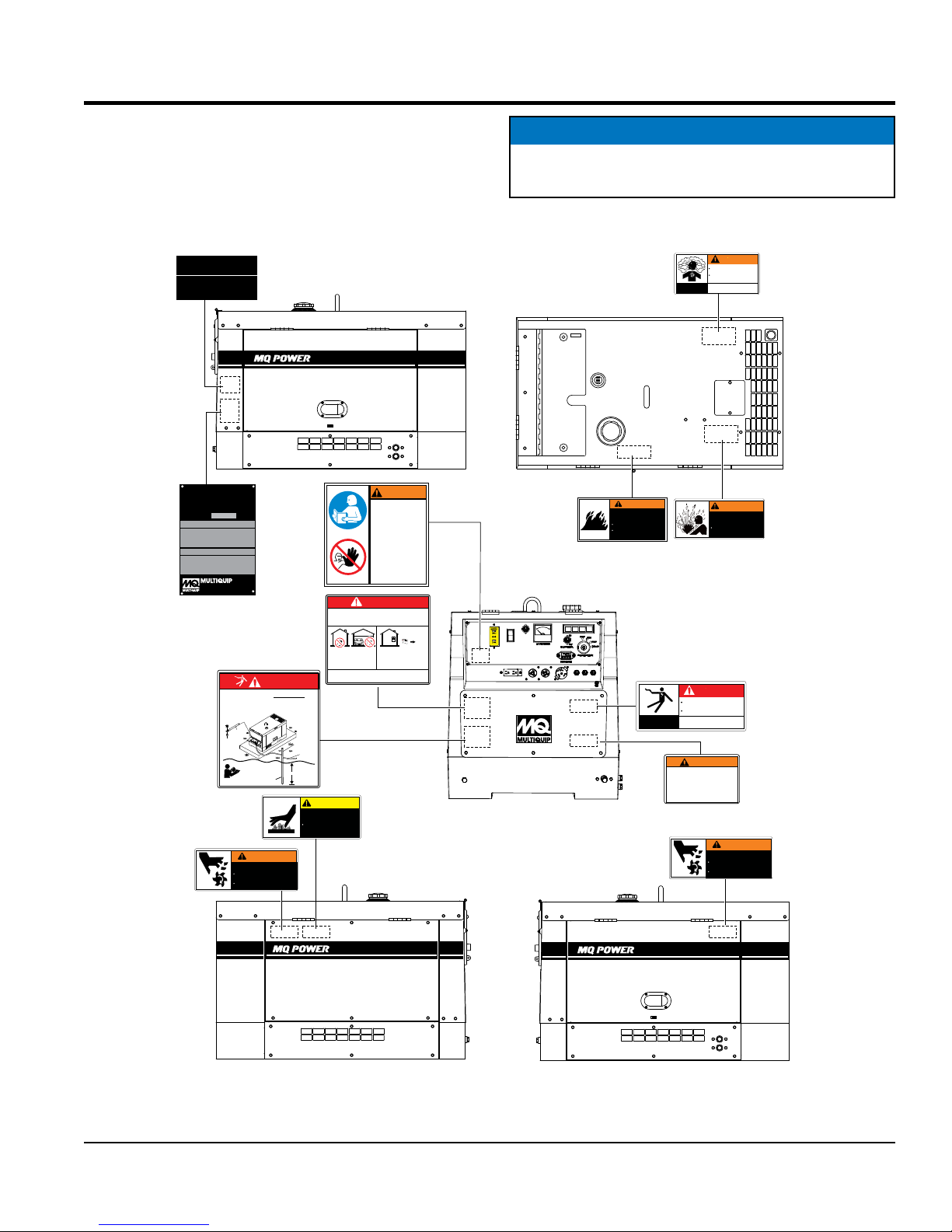
NAMEPLATE/SAFETY INFORMATION
NAMEPLATE AND SAFETY LABELS
Safety labels are attached to the generator as shown in
Figure 1. Keep these safety labels clean at all times. When
the safety labels become worn or damaged, contact your
nearest dealer or the Multiquip Parts Dept.
EMISSION CONTROL INFORMATION
SUPPLEMENTAL LABEL
KUBOTA Corporation
KUBOTA
XXXXX
XXXXXX
XXXX
XXXXX
XXXXXXX
XXXX
WHISPERWATT
DIESEL POWERED AC GENERATOR
MODEL: DA-7000SSA3
SERIAL No.
XXXXXXX
XXXXXXX
XXXXXXX
XXXXXXX
XXXXXXX
XXXXXXX
XXXXXXX
XXXXXXX
XXXXXXX
XXXXXXX
XXXXXXX
XXXXXXX
XXXXXXX
XXXXXXX
XXXXXXX
XXXXXXX
XXXXXXX
XXXXXXX
XXXXXXX
XXXXXXX
XXXXXXX
XXXXXXX
XXXXXXX
XXXXXXX
XXXXX
XXXXX
XXXXXX
XXXXXX
XXXX
XXXX
XXXXX
XXXXX
XXXXXXX
XXXXXXX
XXXX
XXXX
XXXXXXX
AC GENERATOR
XXXXX
XXXXXX
XXXX
XXXXX
XXXXXXX
XXXX
DIESEL ENGINE
XXXXX
XXXXXX
XXXX
XXXXX
XXXXXXX
XXXX
INC.
THE POSSIBILITY EXISTS OF ELECTROCUTION IF
GENERATOR/WELDER IS NOT PROPERLY GROUNDED.
ALWAYS CONNECT EARTH GROUND (GROUND
ROD) TO GENERATOR G.F.C.I. GROUND TERMINAL.
GROUND
GENERATOR
CABLE
GROUND LUG
#8 MINIMUM
G.F.C.I
GROUND
STUD
FOR FURTHER GROUNDING
INSTRUCTIONS, READ MANUAL
WARNING
MOVING PARTS can cause
severe injury.
DO NOT operate with doors
open.
Stop engine before servicing.
DANGER
GROUND ROD
FOR EARTH
GROUND
CONNECT TO
BUILDING
GROUND
(OPTION)
8 FT. MINIMUM
REFERENCE
NEC 250-52(C)
D93110000
B90400040
DANGER
Using a generator indoors CAN KILL YOU IN MINUTES.
Generator exhaust contains carbon monoxide. This is
a poison gas you cannot see or smell.
NEUTRAL BONDED TO FRAME
120V
120
V
GAC-2.2H
NEUTRE MIS A LA MASSE A
15A
LA CARCASSE DU MOTEUR
POWERED by
Honda Engines
211052
AC CIRCUIT BREAKER
INTERRUPTEUR DE
OFF
GR PRISE DE
COURANT PRINCIPAL
TERRE
NEVER use inside a home
or garage. Even if doors
and windows are open.
Avoid other generator hazards.
READ MANUAL BEFORE USE.
CAUTION
HOT PARTS can burn skin.
DO NOT get on the roof
until the machine is
cooled sufficiently.
B90400030
7000
WARNING
To avoid injury,
you MUST read
and understand
operator’s manual
before using this
machine.
This machine to
be operated by
qualified
personnel only.
Ask for training
as needed.
NEUTRAL BONDED TO FRAME
120V
120
V
GAC-2.2H
NEUTRE MIS A LA MASSE A
15A
LA CARCASSE DU MOTEUR
POWERED by
Honda Engines
211052
AC CIRCUIT BREAKER
INTERRUPTEUR DE
OFF
GR PRISE DE
COURANT PRINCIPAL
TERRE
ONLY use OUTSIDE and
far away from windows,
doors, and vents.
P/N A9111000
NEUTRAL BONDED TO FRAME
120V
120
V
GAC-2.2H
NEUTRE MIS A LA MASSE A
15A
LA CARCASSE DU MOTEUR
POWERED by
Honda Engines
211052
AC CIRCUIT BREAKER
INTERRUPTEUR DE
OFF
GR PRISE DE
COURANT PRINCIPAL
TERRE
A90400001
NOTICE
For safety label part numbers, reference parts manual..
WARNING
Only operate machine in well ventilated
areas.
DO NOT inhale exhaust gases.
S-4984
Only qualified personnel should
DANGEROUS
install, use or service this
GAS
equipment.
WARNING
DIESEL FUEL can cause
fire or explosion.
Stop engine before fueling.
Keep cigarettes, sparks
and flame away.
B90450000
F
P
A
O
U
W
L
E
T
R
MANUAL RESET
S-4985
ELECTRICAL
SHOCK
HAZARD
Operation of this equipment may create
sparks that can start fires around dry
vegetation.
A spark arrestor may be required.
The operator should contact local fire
agencies for laws or regulation relating
to fire prevention requirements.
WARNING
HOT COOLANT can cause
severe burns.
Do not remove cap if
radiator is hot.
DANGER
Do not touch output terminals or
internal wiring while unit is operating.
Turn off power before servicing.
Only qualified personnel should
install, use or service this
equipment.
WARNING
A91110010
WARNING
MOVING PARTS can cause
severe injury.
DO NOT operate with doors
open.
Stop engine before servicing.
B90410010
B90400040
Figure 1. Nameplate And Safety Decals
DA7000SSA3 GENERATOR• OPERATION MANUAL — REV. #0 (02/13/19) — PAGE 5
7000
7000
Page 6
SAFETY INFORMATION
Do not operate or service the equipment before reading the
entire manual. Safety precautions should be followed at all
times when operating this equipment. Failure to read and
understand the safety messages and operating instructions
could result in injury to yourself and others.
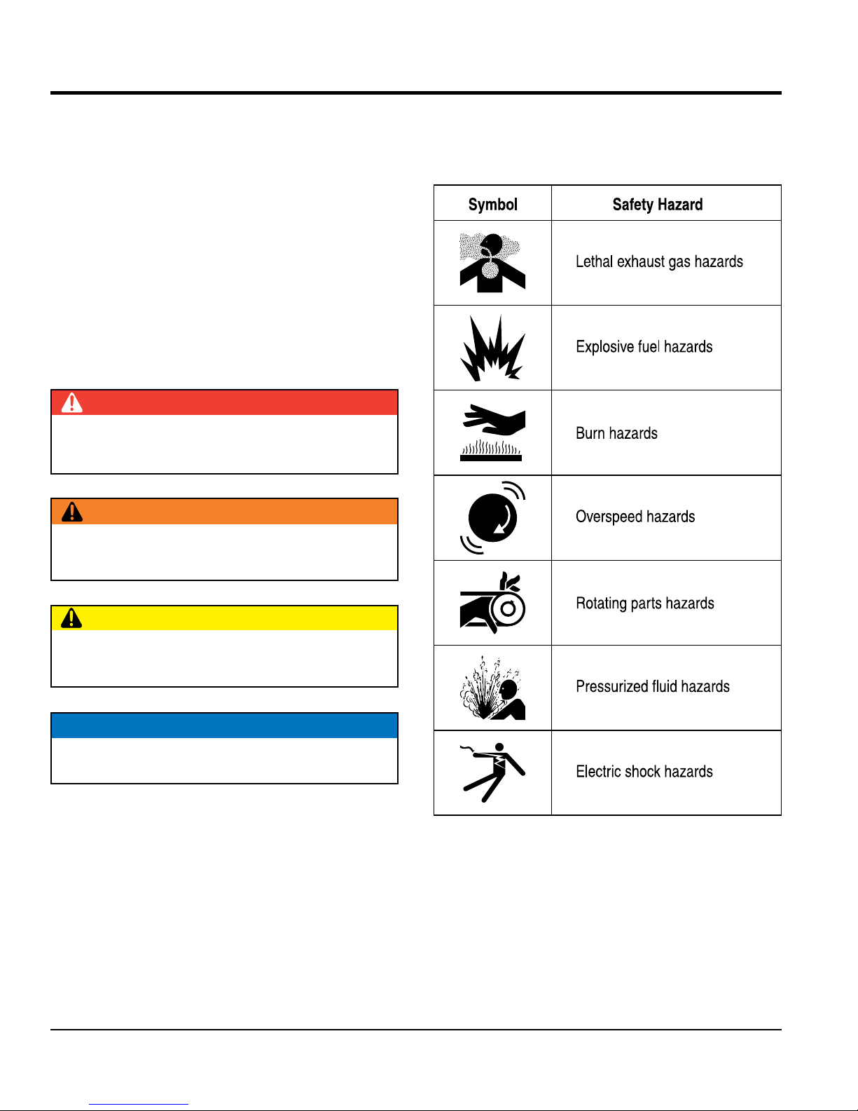
SAFETY MESSAGES
The four safety messages shown below will inform you
about potential hazards that could injure you or others. The
safety messages specifi cally address the level of exposure
to the operator and are preceded by one of four words:
DANGER, WARNING, CAUTION
SAFETY SYMBOLS
Potential hazards associated with the operation of this
equipment will be referenced with hazard symbols which
may appear throughout this manual in conjunction with
safety messages.
DANGER
Indicates a hazardous situation which, if not avoided,
WILL result in DEATH or SERIOUS INJURY.
WARNING
Indicates a hazardous situation which, if not avoided,
COULD result in DEATH or SERIOUS INJURY.
or NOTICE.
CAUTION
Indicates a hazardous situation which, if not avoided,
COULD result in MINOR or MODERATE INJURY.
NOTICE
Addresses practices not related to personal injury.
PAGE 6 — DA7000SSA3 GENERATOR• OPERATION MANUAL — REV. #0 (02/13/19)
Page 7

SAFETY INFORMATION
GENERAL SAFETY
NEVER use accessories or attachments that are not
recommended by MQ Power for this equipment. Damage
Also, know the
and
This information will be invaluable in
emergency or safety devices.
These devices are intended for operator safety.
Disconnection of these devices can cause severe injury,
bodily harm or even death. Disconnection of any of these
lubricate components or attempt service on a
Fix damage to machine and replace any broken parts
store equipment properly when it is not being
used. Equipment should be stored in a clean, dry location
out of the reach of children and unauthorized personnel.
CAUTION
NEVER operate this equipment without proper protective
clothing, shatterproof glasses, respiratory protection,
hearing protection, steel-toed boots and other protective
devices required by the job or city and state regulations.
NEVER operate this equipment when not
feeling well due to fatigue, illness or when
under medication.
NEVER operate this equipment under the infl uence of
drugs or alcohol.
ALWAYS check the equipment for loosened threads or
bolts before starting.
DO NOT use the equipment for any purpose other than
its intended purposes or applications.
to the equipment and/or injury to user may result.
ALWAYS know the location of the nearest
fi re extinguisher.
ALWAYS know the location of the nearest
fi rst aid kit.
ALWAYS know the location of the nearest
phone or keep a phone on the job site.
phone numbers of the nearest ambulance, doctor
fi re department.
the case of an emergency.
GENERATOR SAFETY
DANGER
NEVER operate the equipment in an explosive
atmosphere or near combustible materials. An
explosion or fi re could result causing severe
bodily harm or even death.
WARNING
NOTICE
This equipment should only be operated by trained and
qualifi ed personnel 18 years of age and older.
Whenever necessary, replace nameplate, operation and
safety decals when they become diffi cult read.
Manufacturer does not assume responsibility for any
accident due to equipment modifi cations. Unauthorized
equipment modifi cation will void all warranties.
NEVER disconnect any
devices will void all warranties.
CAUTION
NEVER
running machine.
NOTICE
ALWAYS ensure generator is on level ground before use.
ALWAYS keep the machine in proper running condition.
immediately.
ALWAYS
DA7000SSA3 GENERATOR• OPERATION MANUAL — REV. #0 (02/13/19) — PAGE 7
Page 8

SAFETY INFORMATION
ENGINE SAFETY
CAUTION
run engine without an air fi lter or with a dirty air
fi lter. Severe engine damage may occur. Service air fi lter
Wet stacking is a common problem with diesel engines
which are operated for extended periods with light or
no load applied. When a diesel engine operates without
suffi cient load (less than 40% of the rated output), it will
not operate at its optimum temperature. This will allow
unburned fuel to accumulate in the exhaust system,
which can foul the fuel injectors, engine valves and
exhaust system, including turbochargers, and reduce
it must be able to provide fuel and air in the proper ratio
and at a high enough engine temperature for the engine
Wet stacking does not usually cause any permanent
damage and can be alleviated if additional load is
applied to relieve the condition. It can reduce the system
performance and increase maintenance. Applying an
increasing load over a period of time until the excess
fuel is burned off and the system capacity is reached
usually can repair the condition. This can take several
State Health Safety Codes and Public Resources
Codes specify that in certain locations, spark arresters
must be used on internal combustion engines that use
hydrocarbon fuels. A spark arrester is a device designed
to prevent accidental discharge of sparks or fl ames
from the engine exhaust. Spark arresters are qualifi ed
and rated by the United States Forest Service for this
purpose. In order to comply with local laws regarding
spark arresters, consult the engine distributor or the
DANGER
The engine fuel exhaust gases contain poisonous carbon
monoxide. This gas is colorless and odorless, and can
cause death if inhaled.
The engine of this equipment
requires an adequate free
fl ow of cooling air. NEVER
operate this equipment in
any enclosed or narrow area
where free fl ow of the air is
restricted. If the air fl ow is
restricted it will cause injury to people and property and
serious damage to the equipment or engine.
WARNING
DO NOT place hands or fingers inside engine
compartment when engine is running.
NEVER operate the engine with heat shields or
guards removed.
Keep fi ngers, hands hair and clothing away
from all moving parts to prevent injury.
DO NOT operate generator with doors
open. Stop the engine before servicing.
DO NOT remove the radiator cap while the
engine is hot. High pressure boiling water
will gush out of the radiator and severely
scald any persons in the general area of
the generator.
DO NOT remove the coolant drain plug while the engine
is hot. Hot coolant will gush out of the coolant tank and
severely scald any persons in the general area of the
generator.
DO NOT remove the engine oil drain plug while the
engine is hot. Hot oil will gush out of the oil tank and
severely scald any persons in the general area of the
generator.
NEVER touch the hot exhaust manifold,
muffl er or cylinder. Allow these parts to cool
before servicing equipment.
NOTICE
NEVER
frequently to prevent engine malfunction.
NEVER tamper with the factory settings
of the engine or engine governor. Damage
to the engine or equipment can result
if operating in speed ranges above the
maximum allowable.
the operating performance.
In order for a diesel engine to operate at peak effi ciency,
to completely burn all of the fuel.
hours to burn off the accumulated unburned fuel.
Operation of the generator may create sparks that
can start fi res around dry vegetation, A spark arrestor
may be required. The operator should contact local fi re
agencies for laws or regulations relating to fi re prevention
requirements.
PAGE 8 — DA7000SSA3 GENERATOR• OPERATION MANUAL — REV. #0 (02/13/19)
local Health and Safety Administrator.
Page 9

SAFETY INFORMATION
FUEL SAFETY
TOWING SAFETY
Make sure the hitch and coupling of the towing vehicle
are rated equal to, or greater than the trailer “gross
NEVER
Check the tire air pressure on both towing vehicle and
Trailer tires should be infl ated to 50 psi cold.
safety
attach trailer’s safety chains to towing
make sure the vehicle and trailer directional,
backup, brake and trailer lights are connected and
• Secure portable power cables in cable tray with tie
unless
posted otherwise. Recommended off-road towing is not to
Avoid sudden stops and starts. This can cause skidding,
or jack-knifi ng. Smooth, gradual starts and stops will
Trailer should be adjusted to a level position at all times
Raise and lock trailer wheel stand in up position when
rolling
underneath the trailer’s bumper
Use the trailer’s swivel jack to adjust the trailer height to
DANGER
DO NOT start the engine near spilled fuel or combustible
fl uids. Diesel fuel is extremely fl ammable and its vapors
can cause an explosion if ignited.
ALWAYS refuel in a well-ventilated area, away from
sparks and open fl ames.
ALWAYS use extreme caution when working with
fl ammable liquids.
DO NOT fi ll the fuel tank while the engine is running
or hot.
DO NOT overfi ll tank, since spilled fuel could ignite if it
comes into contact with hot engine parts or sparks from
the ignition system.
Store fuel in appropriate containers, in well-ventilated
areas and away from sparks and fl ames.
NEVER use fuel as a cleaning agent.
DO NOT smoke around or near the
equipment. Fire or explosion could result
from fuel vapors or if fuel is spilled on a
hot engine.
CAUTION
Check with your local county or state safety
towing regulations, in addition to meeting
Department of Transportation (DOT)
Safety Towing Regulations, before towing
your generator.
Refer to MQ Power trailer manual for additional safety
information.
In order to reduce the possibility of an accident while
transporting the generator on public roads, ALWAYS
make sure the trailer that supports the generator and
the towing vehicle are mechanically sound and in good
operating condition.
ALWAYS shutdown engine before transporting
vehicle weight rating.”
ALWAYS inspect the hitch and coupling for wear.
tow a trailer with defective hitches, couplings, chains, etc.
trailer.
Also check the tire tread wear on both vehicles.
ALWAYS make sure the trailer is equipped with a
chain.
ALWAYS properly
vehicle.
ALWAYS
working properly.
DOT Requirements include the following:
• Connect and test electric brake operation.
wraps.
The maximum speed for highway towing is 55 MPH
exceed 15 MPH or less depending on type of terrain.
improve towing.
Avoid sharp turns to prevent rolling.
when towing.
towing.
Place chock blocks underneath wheel to prevent
while parked.
Place support blocks
to prevent tipping while parked.
a level position while parked.
DA7000SSA3 GENERATOR• OPERATION MANUAL — REV. #0 (02/13/19) — PAGE 9
Page 10

ELECTRICAL SAFETY
DANGER
Power Cord/Cable Safety
Make sure power cables are securely connected to the
generator’s output receptacles. Incorrect connections
may cause electrical shock and damage to the generator.
make certain that proper power or extension
cord has been selected for the job. See Cable Selection
make sure that electrical circuits are properly
grounded to a suitable earth ground (ground rod) per
the National Electrical Code (NEC) and local codes
Severe injury or death by
can result from operating an ungrounded
drop the battery. There is a possibility that the
keep the battery charged. If the battery is not
recharge the battery in a well-ventilated
environment to avoid the risk of a dangerous concentration
DO NOT touch output terminals during
operation. Contact with output terminals
during operation can cause electrocution,
electrical shock or burn.
The electrical voltage required to
operate the generator can cause severe
injury or even death through physical contact with live
circuits. Turn generator and all circuit breakers OFF
before performing maintenance on the generator or
making contact with output terminals.
SAFETY INFORMATION
NOTICE
ALWAYS
Chart in this manual.
Grounding Safety
DANGER
ALWAYS
NEVER insert any objects into the output
receptacles during operation. This is
extremely dangerous. The possibility exists
of electrical shock, electrocution or
death.
Backfeed to a utility system can cause
electrocution and/or property damage.
NEVER connect the generator to a
building’s electrical system without
a transfer switch or other approved
device. All installations should be
performed by a licensed electrician in accordance with
all applicable laws and electrical codes. Failure to do so
could result in electrical shock or burn, causing serious
injury or even death.
DANGER
NEVER let power cords or cables lay in water.
NEVER stand in water while AC power from the
generator is being transferred to a load.
before operating generator.
electrocution
generator.
NEVER use gas piping as an electrical ground.
BATTERY SAFETY
DANGER
DO NOT
battery will explode.
DO NOT expose the battery to open fl ames,
sparks, cigarettes, etc. The battery contains
combustible gases and liquids. If these
gases and liquids come into contact with a
fl ame or spark, an explosion could occur.
WARNING
ALWAYS wear safety glasses when
handling the battery to avoid eye irritation.
The battery contains acids that can cause
injury to the eyes and skin.
NEVER use damaged or worn cables or cords when
connecting equipment to generator. Inspect for cuts in
the insulation.
NEVER grab or touch a live power
cord or cable with wet hands. The
possibility exists of electrical shock,
electrocution or death.
PAGE 10 — DA7000SSA3 GENERATOR• OPERATION MANUAL — REV. #0 (02/13/19)
Use well-insulated gloves when picking up the battery.
ALWAYS
charged, combustible gas will build up.
ALWAYS
of combustible gasses.
Page 11
If the battery liquid (dilute sulfuric acid) comes into
contact with clothing or skin, rinse skin or clothing
ENVIRONMENTAL SAFETY/
Decommissioning is a controlled process used to safely
retire a piece of equipment that is no longer serviceable.
If the equipment poses an unacceptable and unrepairable
safety risk due to wear or damage or is no longer cost
effective to maintain (beyond life-cycle reliability) and is to
be decommissioned (demolition and dismantlement),be
sure to follow rules below.
EMISSIONS INFORMATION
The diesel engine used in this equipment has been
designed to reduce harmful levels of carbon monoxide
(CO), hydrocarbons (HC) and nitrogen oxides (NOx)
This engine has been certifi ed to meet US EPA Evaporative
Attempting to modify or make adjustments to the engine
emission system by unauthorized personnel without proper
training could damage the equipment or create an unsafe
Additionally, modifying the fuel system may adversely affect
evaporative emissions, resulting in fi nes or other penalties.
The emission control label is an integral part of the emission
If a replacement emission label is needed, please contact
immediately with plenty of water.
If the battery liquid (dilute sulfuric acid) comes into
contact with eyes, rinse eyes immediately with plenty
of water and contact the nearest doctor or hospital to
seek medical attention.
SAFETY INFORMATION
NOTICE
contained in diesel exhaust emissions.
CAUTION
ALWAYS disconnect the NEGATIVE battery terminal
before performing service on the generator.
ALWAYS keep battery cables in good working condition.
Repair or replace all worn cables.
NOTICE
DECOMMISSIONING
DO NOT pour waste or oil directly onto the ground, down
a drain or into any water source.
Contact your country's Department of
Public Works or recycling agency in your
area and arrange for proper disposal of
any electrical components, waste or oil
associated with this equipment.
emissions requirements in the installed confi guration.
condition.
Emission Control Label
system and is strictly controlled by regulations.
The label must remain with the engine for its entire life.
your authorized engine distributor.
When the life cycle of this equipment is over, remove
battery and bring to appropriate facility for lead
reclamation. Use safety precautions when handling
batteries that contain sulfuric acid.
When the life cycle of this equipment is over, it is
recommended that the frame and all other metal parts
be sent to a recycling center.
Metal recycling involves the collection of metal from
discarded products and its transformation into raw
materials to use in manufacturing a new product.
Recyclers and manufacturers alike promote the process
of recycling metal. Using a metal recycling center
promotes energy cost savings.
DA7000SSA3 GENERATOR• OPERATION MANUAL — REV. #0 (02/13/19) — PAGE 11
Page 12
AC Generator
60 Hz AC Power Source
SPECIFICATIONS (GENERATOR)
Table 1. Specifications (Generator)
Model DA7000SSA3
Type 2-Pole Brushless Revolving Field Type
Excitation Solid State, Statically Excited System
Speed 3,600 RPM
Cooling System Self-Ventilation
Max Power Output 7 kW
Continuous Power Output 6 kW
Rated Voltage 120/240V
Current Max/Continuous (120V) 58.3/50 amps
Current Max/Continuous (240V) 29.2/25 amps
Phase Single Phase (4 wire)
Frequency 60 Hz
Power Factor 1
Battery
Dimensions
(L x W x H)
Dry Weight
Wet Weight
12 -35Ah x 1
44.9 X 25.6 X 31.3 in.
(1,140 X 650 X 795 mm)
534 lbs. (242 kg)
598 lbs. (271 kg)
NOTICE
In keeping with Multiquip's policy of constantly
improving its products, the specifications quoted herein
are subject to change without prior notice.
PAGE 12 — DA7000SSA3 GENERATOR• OPERATION MANUAL — REV. #0 (02/13/19)
Page 13

SPECIFICATIONS (ENGINE)
Table 2. Specifications (Engine)
Kubota Engine Model Z482-E4B-DGDE-4
Tier 4
Gen. Enclosure Color White
Type Vertical, water-cooled, 4-cycle diesel engine
Engine
Effects of Altitude and Heat
Bore X Stroke
Displacement 29.23 cu.-in. (479 cm
2.64 in. X 2.68 in.
(67 mm x 68 mm.)
3
)
Number of Cylinders 2
Max Output 12.5~13.9 H.P./3600 R.P.M.
Fuel #2 Diesel Fuel
Fuel Capacity 6.6 gal. (25 liters)
Fuel Consumption 0.69 gals. (2.63 liters)/hr.
Coolant Capacity 2.95 quarts (2.8 liters)
Lube Oil Capacity 2.64 quarts (2.5 liters)
Oil Alert System Ye s
Starting Method Electric Start
Battery 12 Volt @ 35 Ah
The maximum output of the engines listed above are applicable to supplying electrical power for continuous service at
ambient conditions in accordance with SAE Test cord J607. The above ambient conditions are at standard sea level, with
a barometric reading of 29.92 inches and a temperature of 60° F (15.5° C).
Generally, the engine's output power will decrease 3-1/2% for each 1000 feet (305 meters) of altitude above sea level, and
1% for each 10° F (-12.2° C) above the standard temperature of 60° F (15.5° C).
DA7000SSA3 GENERATOR• OPERATION MANUAL — REV. #0 (02/13/19) — PAGE 13
Page 14

A
D
DIMENSIONS
B C
E
F
G
J
K L
Figure 2. Dimensions
Table 3. Dimensions
A B C D
approx. 34.3 in
(870 mm)
E F G H
Housing
Approx. Dry Weight 534 lbs (242 kg)
Approx. Wet Weight 598 lbs (271 kg)
44.9 in
(1140 mm)
I J K L
approx. 40.4 in
(1025 mm)
(740 mm)
(795 mm)
(590 mm)
29.1 in
31.3 in
23.2 in
H
7.9 in
(200 mm)
28.3 in
(720 mm)
25.6 in
(650 mm)
I
approx. 6.5 in
(165 mm)
12.8 in
(325 mm)
approx. 17.9 in
(455 mm)
PAGE 14 — DA7000SSA3 GENERATOR• OPERATION MANUAL — REV. #0 (02/13/19)
Page 15

NOTES
DA7000SSA3 GENERATOR• OPERATION MANUAL — REV. #0 (02/13/19) — PAGE 15
Page 16
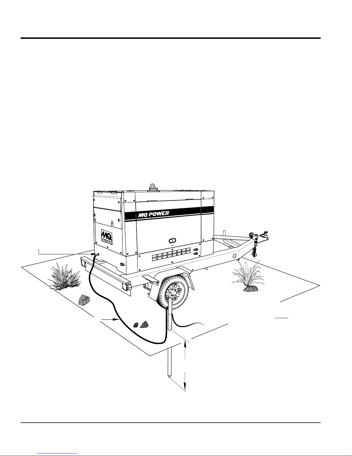
INSTALLATION
CONNECTING THE GROUND
Consult with local Electrical and Safety Codes for proper
connection based on condition of use.
EXAMPLE of how to ground the unit if the condition
of use requires such a device:
The ground terminal on the generator should always be
used to connect the generator to a suitable ground when
required.
Either copper or aluminum wire can be used as the ground
cable. Cable size is determined by the maximum amperage
of the generator. Reference Conductor Grounding Table,
Article 250 of the NEC handbook.
Connect one end of the ground cable terminal to the
generator ground point (Figure 3). Connect the other end
of the ground cable to a suitable earth ground (ground rod).
7000
GENERATOR
GROUND LUG
GROUND CABLE
REFERENCE
NEC ARTICLE 250
8 FT./2.4M (MINIMUM)
Figure 3. Generator Grounding
IF THE GENERATOR IS PROVIDING
ELECTRIC POWER TO A BUILDING
VIA A TRANSFER SWITCH IT MUST
BE CONNECTED TO A GROUND ROD.
PAGE 16 — DA7000SSA3 GENERATOR• OPERATION MANUAL — REV. #0 (02/13/19)
Page 17

INSTALLATION
OUTDOOR INSTALLATION
Install the generator in an area that is free of debris,
bystanders, and overhead obstructions. Make sure the
generator is on secure level ground so that it cannot slide
or shift around. Also install the generator in a manner so
that the exhaust will not be discharged in the direction of
nearby homes.
The installation site must be relatively free from moisture
and dust. All electrical equipment should be protected from
excessive moisture. Failure to do will result in deterioration
of the insulation and will result in short circuits and
grounding.
Foreign materials such as dust, sand, lint and abrasive
materials have a tendency to cause excessive wear to
engine and alternator parts.
CAUTION
Pay close attention to ventilation when operating the
generator inside tunnels and caves. The engine exhaust
contains noxious elements. Engine exhaust must be
routed to a ventilated area.
GENERATOR GROUNDING
NOTICE
The Occupational Safety and Health Administration
(OSHA) and the National Electrical Code (NEC)
recommend that if the generator is providing electrical
power to a structure (home, office shop, trailer or
similar) it must be connected to a grounding electrode
system, such a driven ground rod (Figure 3).
If applicable, to guard against electrical shock and possible
damage to the equipment, it is important to provide a good
EARTH ground, (Figure 3).
NOTICE
ALWAYS check with State, Province, District and
Municipalities for electrical grounding requirements
before using generator.
Article 250 (Grounding) of the NEC handbook provides
guidelines for proper grounding and specifies that the cable
ground shall be connected to the grounding system of the
building as close to the point of cable entry as practical.
INDOOR INSTALLATION
Exhaust gases from diesel engines are extremely
poisonous. Whenever an engine is installed indoors the
exhaust fumes must be vented to the outside. The engine
should be installed at least two feet from any outside wall.
Using an exhaust pipe which is too long or too small can
cause excessive back pressure which will cause the engine
to heat excessively and possibly burn the valves.
MOUNTING
The generator must be mounted on a solid foundation
(such as concrete) and set firmly on the foundation to
isolate vibration of the generator when it is running. The
generator must be mounted at least 6 inches above the floor
or grade level as referenced in the National Fire Protection
Association (NFPA 110, Chapter 7, section 7.4) handbook.
DO NOT remove the metal skids on the bottom of the
generator. They are to resist damage to the bottom of the
generator and to maintain alignment.
1. Use one of the following wire types to connect the
generator to earth ground.
a. Copper
b. Aluminum
NOTICE
Reference Conductor Grounding Table, Article 250
of the NEC handbook for proper conductor wire size.
Wire size is determined by the maximum amperage of
the generator.
2. When grounding of the generator (Figure 3) is required,
connect one end the ground cable to the ground lug
on the generator. Connect the other end of the ground
cable to the ground rod (earth ground).
3. NEC Article 250 specifies that the earth ground rod
should be buried a minimum of 8 ft. into the ground.
NOTICE
When connecting the generator to any buildings
electrical system ALWAYS consult with a licensed
electrician.
DA7000SSA3 GENERATOR• OPERATION MANUAL — REV. #0 (02/13/19) — PAGE 17
Page 18

GENERAL INFORMATION
Generator
The Multiquip DA7000SSA3 is a 6.0 kW (continuous
output), 7.0 kW (max output) A.C. generator designed as
a portable dual purpose power source for 60 Hz (single
phase), 120/240V for lighting facilities, power tools,
submersible pumps and other industrial and construction
machinery.
Control Panel
The control box is provided with the following:
120 VAC Receptacle (5-20R)
120 Twist-Lock Output Receptacle (L5-30R)
120/240 V Twist-Lock Output Receptacle (L14-30R)
120/240 V Twist-Lock Output Receptacle (CS6369)
AC Voltmeter
GFCI Sensing Module
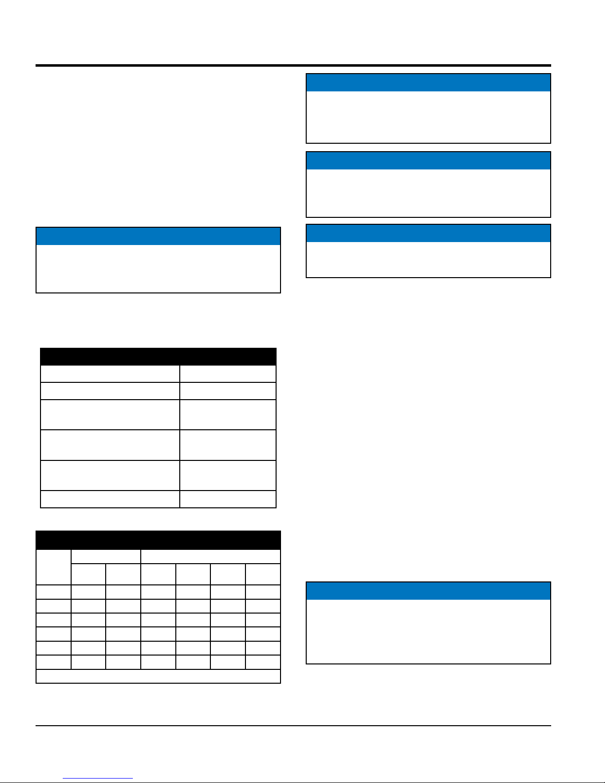
Main Circuit Breaker @25 Amps
30 Amp Circuit Breaker (for L14-30R)
30 Amp Circuit Breaker (for L5-30R)
20 Amp Circuit Breaker (for 5-20R)
Idle Control Switch
Full Power Switch
Starter Switch
Warning Lamp Unit
Hour Meter
Ground Terminal
Engine Protection System
Engine protection fail safe features are provided in the event
of low oil pressure, high coolant temperature and failure of
the battery to charge. If any of the above conditions occur
while operating the generator it will cause a complete unit
shut down.
Battery Charge Alarm
This unit is equipped with a protective shutdown device
that signals the emergency relay and automatically stops
the engine when loss of charge from the engine alternator
occurs. An indicator lamp will be displayed on the control
panel.
Water Temperature Alarm
This unit is equipped with a temperature switch that signals the
emergency relay and automatically stops the engine when the
temperature of the engine coolant becomes abnormally high.
The coolant temperature switch will not function properly if
the machine is operated with less than the proper amount
of coolant.
Oil Pressure Warning Alarm
This unit is equipped with an oil pressure switch that detects
low oil pressure. If the lubricating oil pressure of this unit
should become abnormally low, the oil pressure switch
signals the emergency relay to shutdown the engine. If
this condition should occur, please refer to the engine
troubleshooting table in this manual.
Idle Control Switch
The DA7000SSA3 generator is provided with an automatic
idle (engine) control capability for noise suppression and
fuel cost reduction. The automatic idle control feature
automatically engages under a no-load condition when the
switch is in the ON position.
With AC loads of more than 100W (such as lighting
equipment, motor-powered tools, submersible water
pumps, etc.), the engine runs at high speed. When a no load
condition is produced, the engine automatically slows down.
Turn the idle control switch to the “ON” (up) position when
AC loads drawing more than 150W are connected. Turn
the idle control switch to the “OFF” (down) position when
AC loads drawing less than 100W or when a magnetic
switch is used.
Excitation System
The DA7000SSA3 generators use a brushless exciter to
create rated output electricity. This system will use the
mechanical energy generated by the 3600 RPM engine
to spin the rotor (or armature) inside the generator (or
alternator end).
Excitation current is sourced from the battery to the
excitation winding in the stator. Current applied to this coil
creates a magnetic field. The rotating armature within the
stator is then induced with AC current.
Engine
The DA7000SSA3 generator is powered by a water-cooled,
4-cycle KUBOTA diesel engine. This engine is designed
to meet every performance requirement of the generator.
Reference Table 2, engine specifications.
In keeping with Multiquip's policy of constantly improving
its products, the specifications quoted herein are subject
to change without prior notice.
PAGE 18 — DA7000SSA3 GENERATOR• OPERATION MANUAL — REV. #0 (02/13/19)
Page 19

COMPONENTS (GENERATOR)
3
1
2
5
18
17
19
13
14
16
15
Figure 4. Generator Components (1 of 3)
4
6
9
11
12
7
8
10
1. Fuel Gauge — Indicates the amount of fuel in the
fuel tank.
2. Lifting Hook — Use this hook to lift the generator.
Maximum weight is 598 lbs. (271 kg).
3. Air Outlet Exhaust — Allows engine exhaust to exit
the generator into the open air. NEVER block this
opening.
4. Radiator Cap Access Cover— Remove this cover to
gain access to radiator cap.
10. Coolant Drain Plug — Remove this plug to drain
coolant from the radiator.
11. Oil Drain Plug — Remove this plug to drain oil from
the engine.
12. Fuel Filter — Prevents dirt and other debris from
entering the fuel system. Replace filter as recommended
in the maintenance section of this manual.
13. Air Inlet Vent — Allows outside air to enter the
generator. NEVER block this opening.
14. Automatic Idle Control Solenoid — Automatically
regulates engine speed depending on load.
15. Battery Terminals — Connect cables to the terminals
on the battery. Always pay close attention to the polarity
of the terminals when connecting to the battery, RED
(positive), and BLACK (negative).
16. Fuel Drain Plug — Remove this plug to drain fuel
from the fuel tank.
17. Battery — Provides +12 VDC power for the generator.
When replacing battery (12V 35 AH) use only
recommended type battery.
18. Fuel Tank — Holds 6.6 gallons (25 liters) of diesel fuel.
19. Frame Ground Terminal — Connect a ground strap
between this lug and a ground rod. Make sure that
the ground rod is terminal is inserted deep into the
ground to provide a good earth ground. Consult with
local Electrical and Safety Codes for proper connection
based on condition of use.
5. Fuel Cap — Remove this cap to add fuel. Add only
#2 Diesel Fuel. Always keep an adequate amount of
fuel in the tank. DO NOT top off. Wipe up any spilled
fuel immediately.
6. Engine Oil Filler Port — Remove this cap to add
engine oil. Use only the recommended oil type. See
Table 6.
7. Radiator — Provides coolant to engine block.
8. Expansion Bottle — Supplies coolant to the radiator
when radiator coolant level is low. Fill to indicated level
as shown on expansion bottle.
9. Oil Filter — Provides filtering for the engine oil. Change
oil filter as recommended in the maintenance section
of this manual.
DA7000SSA3 GENERATOR• OPERATION MANUAL — REV. #0 (02/13/19) — PAGE 19
Page 20

20 21
COMPONENTS (GENERATOR)
F
P
A
O
U
W
L
E
T
R
AUTO RESET
AC CIRCUIT BREAKER
A91110000
G.F.C.I. PROTECTED
WHISPERWATT
7kW AC GENERATOR
22
Figure 5. Generator Components (2 of 3)
ON
OFF
120V
I
25
O
240/120V
FULL POWER
SWITCH
0
AC VOLTMETER
ALL RECEPTACLES
G.F.C.I. PROTECTED
240
120
V
ON
OFF
IDLE CONTROL
QUARTZ
HOUR METER
STOP
STARTER SWITCH
CIRCUIT BREAKER
for 120V
for 120V
20A
30A
RUN
S-3031
for 120V/240V
30A
HEAT
START
29
23
24
25 26
27
28
20. GFCI Sensing Module — Interrupts power, by opening
the main breaker, when a ground fault exists.
21. Main Breaker — 2-pole, 25 Amp circuit breaker
protects the generator from short circuiting or
overloading. When starting the generator, always have
this circuit breaker placed in the OFF position. Also
protects the CS6369 receptacle.
22. NEMA 5-20R Duplex Receptacle — Provides 120V,
60 Hz output at 20 amps.
23. NEMA L5-30R Receptacle — Twist-lock receptacle
provides 120V, 60 Hz output at 30 amps, depending
on the position of the full power switch.
24. NEMA L14-30R Receptacle — Twist-lock receptacle
provides 240V, 60 Hz output at 15 amps, or 120V, 60 Hz
at 30 amps, depending on the position of the full power
switch.
25. CS6369 Receptacle — Twist-lock receptacle provides
240V, 60 Hz output at 25 amps, or 120V, 60 Hz at
50 amps, depending on the position of the full power
switch.
26. 20 Amp Breaker (for 5-20R) — Single-pole, 20 Amp
circuit breaker protects the 120V duplex receptacle.
When starting the generator, always have this circuit
breaker placed in the "OFF" positio.
27. 30 Amp Breaker (for L5-30R) — Single-pole, 30 Amp
circuit breaker protects the 120V twist-lock receptacle.
When starting the generator, always have this circuit
breaker placed in the "OFF" position.
28. 30 Amp Breaker (for L14-30R) — 2-pole, 30 Amp
circuit breaker protects the 120/240V twist-lock
receptacle. When starting the generator, always have
this circuit breaker placed in the "OFF" position.
29. Ground Terminal GFCI Module — Used to connect
external equipment grounds so that the GFCI sensing
module will have a ground path.
PAGE 20 — DA7000SSA3 GENERATOR• OPERATION MANUAL — REV. #0 (02/13/19)
Page 21

30
F
P
A
O
U
W
L
E
T
R
AUTO RESET
AC CIRCUIT BREAKER
G.F.C.I. PROTECTED
A91110000
WHISPERWATT
7kW AC GENERATOR
31
120V
ON
I
25
240/120V
O
FULL POWER
OFF
SWITCH
ALL RECEPTACLES
G.F.C.I. PROTECTED
0
V
AC VOLTMETER
33
240
120
IDLE CONTROL
QUARTZ
HOUR METER
ON
OFF
32
STOP
STARTER SWITCH
CIRCUIT BREAKER
for 120V
for 120V
20A
30A
RUN
S-3031
HEAT
START
for 120V/240V
30A
34
Figure 6. Generator Components (3 of 3)
30. AC Voltmeter — This voltmeter indicates (with a
mark) the rated 60 Hz (single-phase) output voltage.
In addition the voltmeter can also be used as a
diagnostic tool. If the voltmeter indicator (needle) is
below the rated voltage, engine problems may exist
(low/high RPM's). To prevent damage to the generator
or power tools turn the generator OFF and consult your
authorized Multiquip service dealer.
31. Idle Control Switch — The generator is provided with
an automatic idle control device for noise suppression
and reduced fuel consumption.
The automatic idle control automatically engages under
a no-load condition. With the automatic idle control
switched ON, the engine revolutions will automatically
drop to about 2200 rpm (low-speed operation) within
3 seconds after the load stops. When the operation is
resumed, the engine speed is automatically increased
to about 3600 rpm (high-speed operation) as soon as
the load is connected.
COMPONENTS (GENERATOR)
32. Engine Warning Lamps — There are four engine
warning lamps, they are defined as follows:
a. Low Oil Pressure Alarm Lamp — During normal
operation of the generator this lamp
will remain OFF. When the ignition
switch is placed in the RUN position
to start the engine, the lamp will be
ON. When the oil pressure rises
after start-up the lamp will go OFF.
If this lamp is ever lit (ON) during normal operation
of the generator, the emergency shutdown system
will stop the engine automatically.
b. Water Temperature Alarm Lamp — This lamp
goes ON when the cooling water
temperature rises abnormally. If
the lamp goes ON during normal
operation of the generator, the
emergency shutdown system will
stop the engine automatically.
c. Battery Charge Alarm Lamp — This lamp is
ON when the output voltage of
the alternator drops below a set
value. If this lamp is ON during
normal operation, the emergency
shutdown system will immediately
stop the engine.
d. Pre-Heat Lamp — The pre-heat lamp will be ON
during the pre-heating cycle (cold weather
conditions). When the pre-heat cycle is completed
the lamp will turn OFF and the engine can be
started.
In addition this lamp displays
engine trouble shooting faults via
flashes (blinking). See engine
trouble codes in the maintenance
section of this manual.
DA7000SSA3 GENERATOR• OPERATION MANUAL — REV. #0 (02/13/19) — PAGE 21
33. Starter Switch — With key inserted turn clockwise to
start engine.
34. Hour Meter — Indicates number of hours machine
has been in use or hours engine was run.
Page 22

35
COMPONENTS (GENERATOR)
120V
ON
F
P
O
W
E
R
AUT0 RESET
A91110000
WHISPERWATT
7kW AC GENERATOR
I
A
U
L
T
AC CIRCUIT BREAKER
G.F.C.I. PROTECTED
25
O
OFF
240/120V
FULL POWER
SWITCH
G.F.C.I. PROTECTED
Figure 7. Full Power Switch
35. Full Power Switch — The generator is provided with
a full power switch. See Figure 8 and Figure 9 for
simplified wiring diagrams of the dual voltage system.
When the full power switch is in the 120 volt position
(up), you can access the full rated power of the
generator at 120 volts from the duplex receptacle and
the 120 volt twist-lock receptacle, or a combination of
both receptacles as long as the total load does not
exceed the generating set capacity.
CB
U1
W
V1
U2
V2
V
SW 120V
56
789
4
123
Figure 8. 120V Full Power Switch
Simplified Diagram (Up Position)
B V
CB1
CB1
X
CB3
CON3
G
W
CON4
CON1
CON2
Y
W
G
V
Y
G
V
Y
Y
22
240
0
120
V
ON
STOP
RUN
for 120V
30A
HEAT
START
S-3031
for 120V/240V
30A
AC VOLTMETER
ALL RECEPTACLES
OFF
IDLE CONTROL
QUARTZ
HOUR METER
STARTER SWITCH
CIRCUIT BREAKER
for 120V
20A
When the full power switch is in the 240 volt position
(down), you can access half of the rated power of the
generator at 120 volts from the duplex receptacle and
up to half of the rated power of the generator at 120
volts from the 120 volt twist-lock receptacle, or full
rated power of the generator at 240 volts from the 240V
twist-lock receptacle.
CB
U1
W
V1
U2
V2
V
SW 120V/240V
56
789
4
123
Figure 9. 240/120V Full Power Switch
Simplified Diagram (Down Position)
B V
CB1
CB1
X
W
CON3
G
CON4
Y
22
CB3
NOTICE
CON1
CON2
Y
W
G
V
Y
G
V
Y
PAGE 22 — DA7000SSA3 GENERATOR• OPERATION MANUAL — REV. #0 (02/13/19)
When using a combination of receptacles, total load
should not exceed the rated capacity of the generator.
Page 23

COMPONENTS (ENGINE)
1
A
2
8
Figure 10. Kubota Z482 Diesel Engine
INITIAL SERVICING
The engine (Figure 10) must be checked for proper
lubrication and filled with fuel prior to operation. Refer to
the manufacturer's engine manual for instructions and
details of operation and servicing.
1. Muffler — Used to reduce noise and emissions.
NEVER touch muffler when the generator is in use.
Always allow time for engine to cool before servicing.
3
7
4
A
5
6
13
14
7. Oil Pressure Switch — Monitors engine oil pressure.
In the event of low oil pressure engine will shutdown.
8. V-Belt — ALWAYS make sure V-belt is properly
tensioned. A loose or defective V-belt can adversely
affect the performance of the generator.
9. Injector Pump — Provides fuel under pressure to the
injector nozzles.
9
10
11
12
2. Cooling Fan Blades — Make sure cooling fan blades
are not bent or broken. A damaged fan blade can cause
the engine to run hot and overheat.
3. Oil Filler Cap — Remove this cap to add oil. Fill with
recommended type oil as listed in Table 6.
4. Air Filter — Prevents dirt and other debris from
entering the air intake system. Loosen clips on side
of air filter canister to gain access to filter element.
Replace with manufacturer's recommended type air
cleaner only.
5. Alternator — Provides power to the +12VDC electrical
system. Replace with only manufactures recommended
type alternator.
6. Starter — Starts engine when ignition key is rotated
clockwise to the "ON" position.
DA7000SSA3 GENERATOR• OPERATION MANUAL — REV. #0 (02/13/19) — PAGE 23
10. Speed Control Lever — Controls engine speed. This
lever is factory set at 3600 rpm to maintain proper
voltage and frequency. DO NOT adjust this lever out
of factory range.
11. Fuel Feed Pump — Pumps fuel to the injection system.
12. Oil Dip Stick/Gauge — Remove to check amount
and condition of oil in crankcase. Refill or replace with
recommended type oil as listed in Table 6.
13. Oil Filter — Spin-on type, filters oil contaminants.
Replace filter as recommended in the maintenance
section of this manual.
14. Oil Drain Plug — Remove to drain crankcase oil.
Fill with recommended type oil as listed in Table 6.
Crankcase holds a maximum of 2.64 quarts (2.5 liters)
of motor oil.
Page 24
LOAD APPLICATIONS
SINGLE PHASE LOAD — 60 HZ
Always be sure to check the nameplate on the generators
and equipment to insure the wattage, amperage and
frequency requirements are satisfactorily supplied by the
generators for operating the equipment.
Generally, the wattage listed on the nameplate of the
equipment is its rated output. Equipment may require
130—150% more wattage than the rating on the nameplate,
as the wattage is influenced by the efficiency, power factor
and starting system of the equipment.
NOTICE
If wattage is not given on the equipment's name plate,
approximate wattage may be determined by multiplying
nameplate voltage by the nameplate amperage
WATTS = VOLTAGE x AMPERAGE
The power factor of this generators is 1.0 See Table 4 below
when connecting loads.
Table 4. Power Factor By Load
Type Of Load Power Factor
Single-phase induction motors 0.4 - 0.75
Electric heaters, incandescent
lamps
Fluorescent lamps, mercury
lamps
Electronic devices,
communication equipment
1.0
0.4 - 0.9
1.0
NOTICE
The idle control device is operated at a minimum load
capacity of 100W. If the load capacity is less than 100W,
place the idle control switch in the OFF position.
NOTICE
When using a combination of dual receptacles, total
load should not exceed the rated capacity of the
generator.
NOTICE
When connecting power tools or equipment pay close
attention to the required starting current capacity.
To determine the running wattage for your load, multiply the
running wattage as indicated by steps 1, 2, and 3 below:
1. INCANDESCENT LOADS
Lights, heaters and similar appliances.
total the running wattage and multiply by 1.
Example:
29 light bulbs @ 100W each = 2.9 kW
use a 3 kW generator.
2. SMALL MOTORS
Drills and other small power tools.
Total the running wattage and multiply by 2.
Example:
A 1 inch drill runs at 1 kW
use a 2 kW generator
Common power tools 0.8
Table 5. Cable Selection (60 Hz, Single Phase Operation)
Current
in
Amperes
2.5 300 600 1000 ft. 600 ft. 375 ft. 250 ft.
5 600 1200 500 ft. 300 ft. 200 ft. 125 ft.
7.5 900 1800 350 ft. 200 ft. 125 ft. 100 ft.
10 1200 2400 250 ft. 150 ft. 100 ft.
15 1800 3600 150 ft. 100 ft. 65 ft.
20 2400 4800 125 ft. 75 ft. 50 ft.
Load in Watts Maximum Allowable Cable Length
At 100
Volts
CAUTION: Equipment damage can result from low voltage
At 200
Volts
#10 Wire #12 Wire #14 Wire #16 Wire
PAGE 24 — DA7000SSA3 GENERATOR• OPERATION MANUAL — REV. #0 (02/13/19)
3. LARGE MOTORS
Submersible pumps, table saws etc.
Total the running wattage and multiply by 3.
Example:
A conveyor belt runs at 8 kW
use a 24 kW generator.
NOTICE
Motors and motor-driven equipment draw much greater
current for starting than during operation. Always use
an adequate size extension cable which can carry the
required load.
Page 25
INSPECTION/SETUP
EXTENSION CABLES
When electric power is to be provided to various tools or
loads at some distance from the generator, extension cords
are normally used. Cables should be sized to allow for
distance in length and amperage so that the voltage
drop between the generator and point of use (load) is
held to a minimum. Use the cable selection chart (Table 5)
as a guide for selecting proper cable size.
GENERAL INSPECTION PRIOR TO OPERATION
Power Tools (Grounding)
When using power tools or electrical equipment requireing
AC power from the generator, make sure power tool cord
has a ground pin or is double insulated as shown in Figure 11.
TWIST-LOCK
RECEPTACLES
GROUND
PIN
CIRCUIT BREAKERS
ALWAYS place the main, and aux circuit breakers in the
OFF position prior to starting the engine.
Figure 12. Main/Aux. Breakers OFF
GROUND
PIN REMOVED
Figure 11. Ground Pin
GROUND
PIN
3-PRONGED
AC PLUG
DOUBLE
INSULATED
DUPLEX
RECEPTACLE
NOTICE
Double-insulated power tools and small appliances
have specially insulated housings that eliminate the
need for a ground. These types of double-insulated
power cords are designed so that no part of the device
will be electrically live even if the internal insulation fails.
DA7000SSA3 GENERATOR• OPERATION MANUAL — REV. #0 (02/13/19) — PAGE 25
Page 26

BEFORE STARTING
1. Read safety instructions at the beginning of manual.
2. Clean the generator, removing dirt and dust, particularly
the engine cooling air inlet. Caution must be taken to
ensure generator is 100% dry before use.
3. Check the air filter for dirt and dust. If air filter is dirty,
replace air filter with a new one as required.
4. Check fastening nuts and bolts for tightness
ENGINE OIL CHECK
NOTICE
This KUBOTA engine is equipped with a low oil
shutdown capability. A built-in sensor will automatically
turn off the engine should the oil level fall below a safe
operating condition. Make sure the generator is placed
on level ground. Placing the generator on level ground
will ensure that the low oil sensor will function properly.
INSPECTION/SETUP
Figure 14. Engine Oil Dipstick
4. Verify that the engine oil level is maintained between
the H and L markings on the dipstick as referenced in
Figure 14A.
5. If the engine oil level is low (Figure 14C), remove the
oil filler cap (Figure 15) and fill to a safe operating level
(max) as indicated by the dipstick (Figure 14A).
NOTICE
When adding engine oil DO NOT overfill (Figure 14B).
1. To check the engine oil level, place the generator on
secure level ground with the engine stopped.
2. Remove the dipstick from its holder (Figure 13) and
wipe clean.
DIPSTICK
Figure 13. Engine Oil Dipstick Removal
6. Fill with recommended type oil as listed in Table 6.
Maximum oil capacity is 2.64 quarts (2.5 liters).
OIL
FILLER
CAP
MOTOR OIL
3. Re-Insert dipstick, then remove dipstick from its holder.
Check the oil level shown on the dipstick Figure 14.
PAGE 26 — DA7000SSA3 GENERATOR• OPERATION MANUAL — REV. #0 (02/13/19)
Figure 15. Engine Oil Filler Port
Page 27

Table 6. Oil Type
Temperature Oil Type
INSPECTION/SETUP
Above 77° F (25° C)
32°~ 77° F
(0° ~ 25° C)
Below 32° F (0° C)
SAE 30 or SAE10W-30
SAE 15W-40
SAE 20 or SAE10W-30
SAE 15W-40
SAE 10 or SAE10W-30
SAE 15W-40
FUEL CHECK
NOTICE
When refueling, be sure to use a strainer for filtration.
DO NOT top-off fuel. DO NOT fill the tank beyond
capacity. Wipe up any spilled fuel immediately!
Fill the fuel tank with #2 diesel fuel. DO NOT fill the tank
beyond capacity.
Pay attention to the fuel tank capacity when replenishing
fuel. Refer to the fuel tank capacity listed in Table 2.
The fuel tank cap must be closed tightly after filling. Handle
fuel in a safety container. If the container does not have a
spout, use a funnel.
1. Read the fuel gauge located on top of the generator
(Figure 16) to determin if the fuel level is low.
7000
Figure 17. Adding Fuel
DANGER
Motor fuels are highly flammable and can
be dangerous if mishandled. DO NOT
smoke while refueling. DO NOT attempt
to refuel the generator if the engine is hot!,
running or in the dark.
COOLANT (ANTIFREEZE)
Kubota recommends Antifreeze/Summer Coolant for use
in thier engines, which can be purchased in concentrate
(and mixed with 50% demineralized water) or pre-diluted.
See the Kubota Engine Owner's Manual for further details.
WARNING
Figure 16. Fuel Gauge
2. If fuel is low, remove the fuel cap (Figure 17) located
on top of the generator and replenish with clean #2
diesel fuel.
DA7000SSA3 GENERATOR• OPERATION MANUAL — REV. #0 (02/13/19) — PAGE 27
If adding coolant/antifreeze mix to the
radiator, DO NOT remove the radiator cap
until the unit has completely cooled. The
possibility of hot coolant exists which can
cause severe burns.
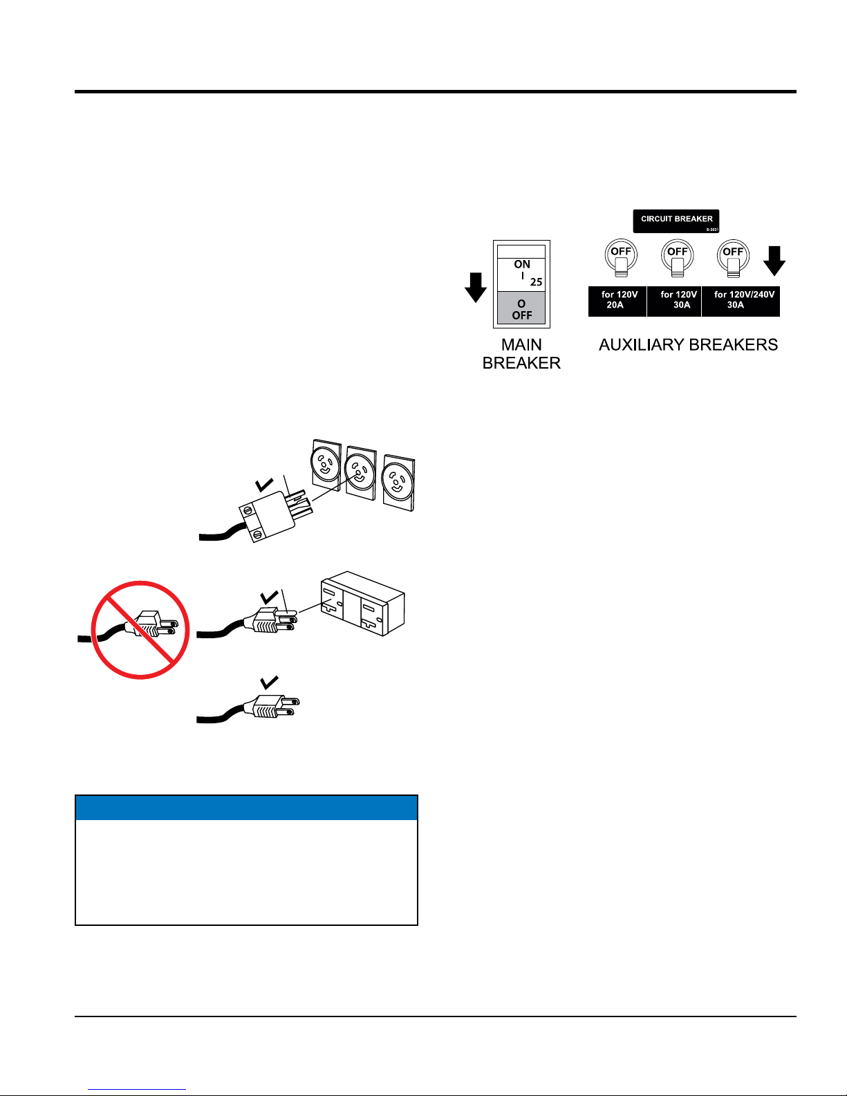
Day-to-day addition of coolant is done from the recovery
tank Figure 18. When adding coolant to the radiator, DO
NOT remove the radiator cap until the unit has completely
cooled. See Table 7 for engine, radiator, and recovery
tank coolant capacities. Make sure the coolant level in the
recovery tank is always between the "FULL" and LOW
markings.
Page 28
INSPECTION/SETUP
NOTICE
Normally, only the coolant level in the recovery tank
needs to be checked. However, the radiator cap should
be opened once a week to verify that coolant is visible
(full) in the radiator.
Table 7. Coolant Capacity
Engine and Radiator .74 gal (2.8 liters)
Reserve Tank (Full) .23 gal (.87 liters)
1. Verify that the coolant level in the coolant recovery tank
is between the FULL and LOW markings as shown in
Figure 18.
CLEANING THE RADIATOR
The engine may overheat if the radiator fins become
overloaded with dust or debris. Periodically clean the
radiator fins with compressed air. Cleaning inside the
machine is dangerous, so clean only with the engine turned
off and the negative battery terminal disconnected.
AIR CLEANER
Periodic cleaning/replacement is necessary. Inspect it in
accordance with the KUBOTA Engine Owner’s Manual.
FAN BELT TENSION
A slack fan belt may contribute to overheating, or to
insufficient charging of the battery. Inspect the fan belt
for damage and wear and adjust it in accordance with the
Kubota Engine Owner's Manual.
The fan belt tension is proper if the fan belt bends 10 to
15 mm (Figure 19) when depressed with the thumb as
shown below.
Figure 18. Coolant Recovery Tank
Operation Freezing Weather
When operating in freezing weather, be certain the proper
amount of antifreeze (Table 8) has been added.
Table 8. Anti-Freeze Operating
Temperatures
Vol %
Anti-Freeze
Freezing Point
°C °F
50 -37 -34
NOTICE
When the antifreeze is mixed with water, the antifreeze
mixing ratio must be less than 50%.
Figure 19. Fan Belt Tension
CAUTION
NEVER place hands near the belts or fan
while the generator set is running.
PAGE 28 — DA7000SSA3 GENERATOR• OPERATION MANUAL — REV. #0 (02/13/19)
Page 29

INSPECTION/SETUP
BATTERY
This unit is of negative ground DO NOT connect in reverse.
Always maintain battery fluid level between the specified
marks. Battery life will be shortened, if the fluid level are
not properly maintained. Add only distilled water when
replenishment is necessary.
DO NOT over fill. Check to see whether the battery
cables are loose. Poor contact may result in poor starting
or malfunctions. Always keep the terminals firmly
tightened. Coating the terminals with an approved battery
terminal treatment compound. Replace battery with only
recommended type battery.
The battery is sufficiently charged if the specific gravity
of the battery fluid is 1.28 (at 68° F). If the specific gravity
should fall to 1.245 or lower, it indicates that the battery is
dead and needs to be recharged or replaced.
Before charging the battery with an external electric source,
be sure to disconnect the battery cables.
BATTERY CABLE INSTALLATION
ALWAYS be sure the battery cables (Figure 20) are
properly connected to the battery terminals as shown below.
The red cable is connected to the positive terminal of the
battery, and the black cable is connected to the negative
terminal of the battery.
When connecting battery do the following:
1. NEVER connect the battery cables to the battery
terminals when the Ignition Switch is in the START
position. ALWAYS make sure that the Ignition Switch
is in the OFF position when connecting the battery.
2. Place a small amount of battery terminal treatment
compound around both battery terminals. This will
ensure a good connection and will help prevent
corrosion around the battery terminals.
NOTICE
If the battery cable is connected incorrectly, electrical
damage to the generator will occur. Pay close attention
to the polarity of the battery when connecting the battery.
CAUTION
Inadequate battery connections may cause poor
starting of the generator, and create other malfunctions.
ALTERNATOR
The polarity of the alternator is negative grounding type.
When an inverted circuit connection takes place, the
circuit will be in short circuit instantaneously resulting the
alternator failure.
CAUTION
ALWAYS disconnect the negative terminal FIRST and
reconnect negative terminal LAST.
NEGATIVE
POSITIVE
Figure 20. Battery Connections
DA7000SSA3 GENERATOR• OPERATION MANUAL — REV. #0 (02/13/19) — PAGE 29
DO NOT put water directly on the alternator. Entry of water
into the alternator can cause corrosion and damage the
alternator.
WIRING
Inspect the entire generator for bad or worn electrical wiring
or connections. If any wiring or connections are exposed
(insulation missing) replace wiring immediately.
PIPING AND HOSE CONNECTION
Inspect all piping, oil hose, and fuel hose connections for
wear and tightness. Tighten all hose clamps and check
hoses for leaks.
If any hose (fuel or oil) lines are defective replace them
immediately.
Page 30

OPERATION
BEFORE STARTING THE ENGINE
CAUTION
The engine’s exhaust contains harmful emissions.
ALWAYS have adequate ventilation when operating.
Direct exhaust away from nearby personnel.
NOTICE
The DA7000SSA3 generator is equipped with a GFCI
sensing module. The purpose of this module is to sense
a ground fault during operation of the generator and
open the main breaker once the ground fault has been
detected.
Multiquip recommends that the GFCI sensing module
be tested before each use of the generator. Refer to the
maintenance section of this manual for testing of the
GFCI sensing module.
1. Open the cabinet door and turn the fuel cock lever
(Figure 21) to the “ON” position.
3. NEVER start the engine with the main circuit breaker
in the ON p osition . Always place circuit breaker (Figure 23)
in the OFF position before starting.
Figure 23. Main Circuit Breaker (OFF)
4. NEVER start the engine with the auxiliary circuit
breakers in the ON position. Always place circuit
breakers (Figure 24) in the OFF position before starting
the engine.
Figure 21. Fuel Cock Lever (ON)
2. NEVER operate the generator with the doors open
(Figure 22). Operation with the doors open may cause
insufficient cooling of the unit, and engine damage may
result. Close the doors for normal operation.
Figure 24. Auxiliary Circuit Breakers (OFF)
STARTING THE ENGINE
1. Insert the key into the starter switch (Figure 25) and
turn it to the “RUN” position..
Figure 25. Starter Switch (RUN)
Figure 22. Generator Doors
PAGE 30 — DA7000SSA3 GENERATOR• OPERATION MANUAL — REV. #0 (02/13/19)
Page 31

OPERATION
2. Verify that the oil pressure, temperature, charge and
glow plug lamps on the " Engine Warning Lamp Unit
Display" are lit. If either lamp is not lit, check the system
and wiring (refer to the Engine Operation Manual)
Figure 26. Engine Warning Lamp Unit (ON)
3. Turn the ignition key to the HEAT position. When the
preheat light goes off, turn the key to the START
position to start the engine. As soon as the engine
starts, release the key. The key will automatically return
to the RUN position.
4. In cold weather conditions, it may be required to extend
the duration of the HEAT position for proper starting.
5. If the engine does not start within 10 seconds after the
key is turned to the START position, wait for about 30
seconds and repeat the procedure as described in
steps 1-3.
NOTICE
Placing the idle control switch (Figure 27) in the OFF
position allows the engine to operate at a maximum
speed of about 3600 RPM's.
When the idle control switch is placed in the up position
(ON), the generator will run at idle speed (2200 RPM's)
until a load is applied, at that time the engine speed
will increase to 3600 RPM's as long as a load is being
applied.
When the load is not in use, the engine speed will drop
back to the idle mode after about 3 seconds.
OUTPUT VOLTAGE VERIFICATION
1. Place main circuit breaker (Figure 28) in the ON
position.
6. When the engine starts, the oil pressure light and
charge light should go out. If these lights stay on,
immediately stop the engine and check the system and
wiring (refer to the Engine Operation Manual).
7. Let the engine idle for five minutes with the Idle Control
Switch (Figure 27) placed in the ON position.
Figure 27. Idle Control Switch (ON)
Figure 28. Main Circuit Breaker (ON)
2. Place auxiliary circuit breakers (Figure 29) in the ON
position.
Figure 29. Auxiliary Circuit Breakers (ON)
3. Read the voltmeter on front panel of generator
(Figure 30) and verify that 120 VAC is displayed. Using
an external voltmeter as shown in Figure 30, verify that
120 VAC is present at the 120V twist-lock and duplex
receptacles.
DA7000SSA3 GENERATOR• OPERATION MANUAL — REV. #0 (02/13/19) — PAGE 31
Page 32
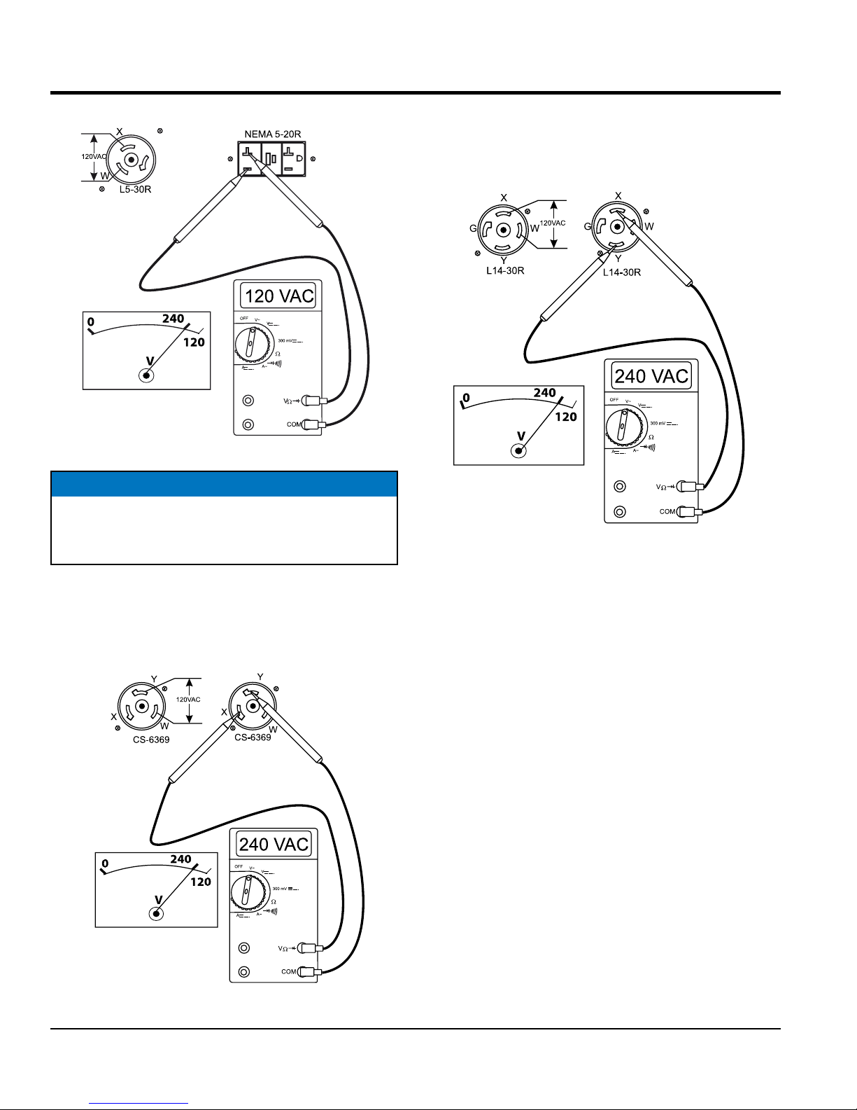
Figure 30. 120V GFCI/L5-30R Receptacles
OPERATION/SHUTDOWN
5. The L14-30R receptacle is a dual voltage receptacle
(120/240 volts). Using an external voltmeter as shown
in Figure 32, verify that 120/240 VAC is present at the
L14-30R twist-lock receptacle.
NOTICE
When using a combination of dual receptacles, total
load should not exceed the rated capacity of the
generator.
4. The CS-6369 receptacle is a dual voltage receptacle
(120/240 volts). Using an external voltmeter as shown
in Figure 31, verify that 120/240 VAC is present at the
CS-6369 twist-lock receptacle.
Figure 32. 120/240V L14-30R Receptacle
6. Connecting of loads (power tools, lighting ect.) to the
generator receptacles can now be done.
Figure 31. 120/240 CS-6369 Receptacle
PAGE 32 — DA7000SSA3 GENERATOR• OPERATION MANUAL — REV. #0 (02/13/19)
Page 33

OPERATION/SHUTDOWN
Stopping the Engine (Normal Shutdown)
1. Place main circuit breaker (Figure 33) in the OFF
position.
Figure 33. Main Circuit Breaker (OFF)
2. Place auxiliary circuit breakers (Figure 34) in the OFF
position.
6.
Figure 36. Starter Switch (Stop Position)
7. Place fuel cock lever (Figure 37) in the OFF position.
Figure 34. Auxiliary Circuit Breakers (OFF)
3. Place idle control switch switch (Figure 35) in the ON
position.
Figure 35. Idle Control switch (ON)
4. Let engine run at idle with no load for 3-5 minutes.
5. Place the starter switch key (Figure 36) in the STOP
position and remove the key.
Figure 37. Fuel Cock Lever (OFF)
8. Remove all load connections from the generator.
Emergency Shutdown
1. Place starter switch key (Figure 25) in STOP position.
Remove key. Place fuel cock lever (Figure 37)) in the
OFF position.
DA7000SSA3 GENERATOR• OPERATION MANUAL — REV. #0 (02/13/19) — PAGE 33
Page 34

PREPARATION FOR LONG TERM STORAGE
Generator Storage
For storage of the generating set for over 30 days, the
following is required:
Run the engine until all the fuel is completely consumed.
Drain the fuel tank completely, or add STA-BIL to the fuel
Completely drain the oil from the crankcase and refill
with fresh oil.
Disconnect the negative battery cable from the battery.
Clean all external parts of the generating set with a cloth.
If generator is mounted on a trailer, jack trailer up and
place on blocks so tires do not touch the ground or block
and completely remove the tires.
Cover the generating set and store in a clean, dry place
PAGE 34 — DA7000SSA3 GENERATOR• OPERATION MANUAL — REV. #0 (02/13/19)
Page 35

MAINTENANCE
Use Table 9 as a general maintenance guideline when
servicing your engine. For more detail engine maintenance
information, refer to the engine owner's manual supplied
with your engine.
Table 9. Engine Maintenance Schedule
EVERY
EVERY 8
YEARS
OR
800 HRS.
DESCRIPTION
(3)
Engine Oil
Oil Filter
Cartridge
Air Cleaner
Element
All Nuts & Bolts
Cooling Fins CHECK X
Fuel Tank CLEAN X
Fuel Filter CLEAN X X
Fuel Filter
Element
Fuel lines CHANGE Every 2 years, replace if necessary (2)
Battery CHANGE X
Radiator Hoses/
Clamps
Radiator
Coolant
Idle Speed CHECK-ADJUST X (2)
Valve Clearance CHECK-ADJUST X (2)
Fan Belt
WATER
SEPARATOR
(1) Service more frequently when used in DUSTY areas.
(2) These items should be serviced by your service dealer, unless you have the proper tools and are mechanically proficient. Refer to the KUBOTA
Shop Manual for service procedures.
(3) For commercial use, log hours of operation to determine proper maintenance intervals.
OPERATION DAILY
CHECK X
CHANGE X X
CHANGE X X X
CHECK X X
CHANGE X (1) X
RETIGHTEN IF
NECESSARY
CHANGE X X
CHANGE Every 2 years, replace if necessary (2)
CHANGE X
CHECK
TIGHTNESS
DRAIN
X
FIRST
MONTH OR
50 HRS.
MONTHS
OR 25 HRS.
EVERY 3
EVERY 6
MONTHS
OR 50 HRS.
YEAR OR
100 HRS.
EVERY
X
X
2 YEARS
OR
200 HRS.
NOTICE
Thoroughly remove dirt and oil from the engine and
control area. Clean or replace the air cleaner elements
as necessary. Check and retighten all fasteners as
necessary.
DA7000SSA3 GENERATOR• OPERATION MANUAL — REV. #0 (02/13/19) — PAGE 35
Page 36

MAINTENANCE
AIR CLEANER
This is a dry type filter. NEVER apply oil to it. If
generator is used in severe dusty areas service air
cleaner element more frequently.
NOTICE
If the engine is operating in very dusty or dry grass
conditions, a clogged air cleaner will result. This can
lead to a loss of power, excessive carbon buildup in
the combustion chamber and high fuel consumption.
Change air cleaner more frequently if these conditions
exist.
Every 250 hours: Remove air cleaner element (Figure 38)
and clean the heavy duty paper element with light spray of
compressed air. Replace the air cleaner as needed.
This Kubota diesel engine is equipped with a replaceable,
high-density paper air cleaner element.
Primary Air Cleaner Elements
CAUTION
6. To clean the primary element (paper air filter) as
referenced in (Figure 38), tap the filter element
several times on a hard surface to remove dirt, or blow
compressed air (not to exceed 30 psi (207 kPa, 2.1
kgf/cm2) through the filter element from the inside out.
Figure 38. Air Cleaner
7. Replace primary air filter elements if it is damaged or
excessively dirty.
Wear protective equipment such as
approved safety glasses or face shields
and dust masks or respirators when
cleaning air filters with compressed air.
1. Release the latches (Figure 38) that secures the cover
to the air cleaner body.
2. Remove the air cleaner cover and set aside.
3. Remove both the primary air cleaner element.
4. Check the air cleaner daily or before starting the engine
5. Check for and correct heavy buildup of dirt and debris
along with loose or damaged components.
NOTICE
Operating the engine with loose or damaged air cleaner
components could allow unfiltered air into the engine
causing premature wear and failure.
8. Clean the inside of the air cleaner body.
9. Reinstall the primary air filter element back into air
cleaner body.
10. Reinstall the air cleaner cover, and secure with latches.
NOTICE
DO NOT run the engine with the air cleaner removed
or without an element.
PAGE 36 — DA7000SSA3 GENERATOR• OPERATION MANUAL — REV. #0 (02/13/19)
Page 37
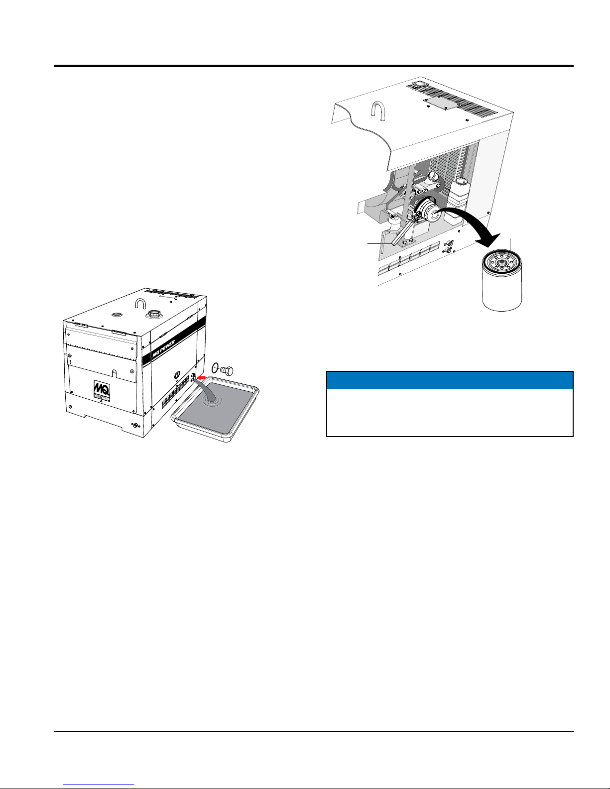
ENGINE OIL
Every 100 hours: Change engine oil after the first 50 hours
of operation and 100 hours thereafter. Always check the
crankcase oil level prior to each use, or when the fuel tank
is filled. Insufficient oil may cause severe engine damage.
Make sure generator is level when checking oil level. The
oil level must be between the two notches on the dipstick
as shown in Figure 14.
1. Remove engine oil drain plug located at the bottom
of the generator enclosure (Figure 39) and drain oil
from crankcase.For best results drain oil while engine
is warm. Reinstall oil drain plug, and add engine oil
as specified in Table 6. Crankcase oil capacity is 2.64
qts. (2.5 liters).
OIL FILTER
WRENCH
MAINTENANCE
RUBBER
SEAL
COAT SEAL
ENGINE
OIL FILTER
CARTRIDGE
WITH THIN
LAYER OF OIL
7000
OIL DRAIN BOLT
AND O-RING
Figure 39. Engine Oil Drain Plug
Oil Filter Cartridge
Every 200 hours: Replace the engine oil filter cartridge
after every 200 hours of operation.
1. Clean the area around the lubricating oil filter head.
2. Coat oil filter seal (Figure 40) with clean engine oil.
3. Install new oil filter first by hand until it makes contact
with the filter head surface. Tighten it another 3/4 turn
using the filter wrench.
Figure 40. Oil Filter Cartridge
4. Install drain bolt with sealing washer and tighten.
NOTICE
When installing the oil filter, coat rubber seal with a
small amount of lubricant (motor oil). DO NOT over-
tighten cartridge. Hand tighten only.
5. Replace engine oil with recommended type oil as listed
in Table 6. For engine oil capacity, see Table 2 (engine
specifications). Fill to upper limit as shown in Figure 14.
6. Run the engine for several minutes. Watch for oil
leakage. Shut the engine down and allow it to sit for
several minutes. Top off the oil to the upper limit on
the dipstick.
DA7000SSA3 GENERATOR• OPERATION MANUAL — REV. #0 (02/13/19) — PAGE 37
Page 38

MAINTENANCE
CLEANING THE FUEL FILTER
Every 100 hours: Clean fuel filter every 100 hours of
operation or once a month to remove dust or water.
1. Place fuel cock lever (Figure 41) in the OFF (close)
position.
2. Disconnect fuel lines from fuel filter.
Figure 41. Fuel Cock Lever (OFF)
3. Unscrew the filter bowl (Figure 42) from the fuel filter
head.
4. Wipe the inside of the fuel filter bowl with a clean cloth
to remove any foreign matter or debris that may have
accumulated. Rinse with diesel fuel.
5. Remove fuel filter paper element, and rinse with diesel
fuel.
6. Reinstall filter bowl and paper element back onto the
filter head. Hand-tighten retaining ring.
7. Inspect all fuel lines every 50 hours.
REPLACING FUEL FILTER ELEMENT
First 50 And Then Every 200 hours: Replace fuel filter
element.
1. Unscrew the filter bowl from the fuel filter
head (Figure 42).
2. Remove fuel filter paper element and replace with a
new one.
3. Replace o-ring and coat with a small amount of clean
15W-40 engine oil.
4. Insert the new fuel filter element into the filter bowl.
5. Reinstall filter bowl first by hand until it makes contact
with the fuel filter head surface. Hand-tighten only.
Figure 42. Fuel Filter Disassembly
6. Remove the air from the fuel system. Reference the
Kubota Operation and Maintenance Manual, "Bleeding
the Fuel System".
AUTOMATIC AIR BLEEDING DEVICE
When the engine stops due to running out of fuel, take
off the fuel filter or fuel piping and re-start the machine in
accordance with the following instructions.
1. Refuel the fuel tank and place the fuel cock lever in
the OPEN position.
2. Place the starter switch key in the START position.
When the engine starter engages, the automatic air
vent device will expel the air inside the fuel system.
3. After 10 to 20 seconds of turning the engine over, the
automatic air vent device would have expelled all the
air out of the fuel system. At this point, the engine will
be able to start.
PAGE 38 — DA7000SSA3 GENERATOR• OPERATION MANUAL — REV. #0 (02/13/19)
Page 39
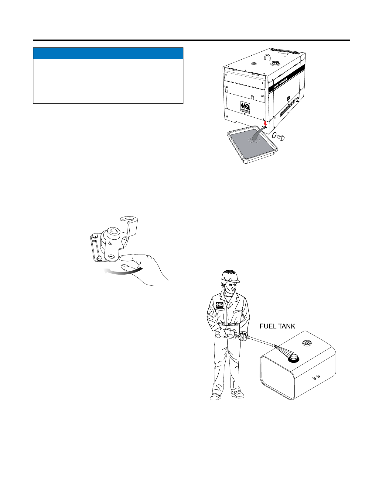
NOTICE
ST
If air enters the fuel injection system of a diesel engine,
starting becomes impossible. After running out of
fuel, or after disassembling the fuel system, bleed
the system.Reference the Kubota Operation and
Maintenance Manual for details.
STOPPING ENGINE (STARTER SWITCH FAILURE)
MAINTENANCE
7000
In the event the engine continues to run even after the
starter switch has been placed in the STOP position,
following the procedure on the next column to turn off the
engine.
1. Place fuel cock lever (Figure 41) in the CLOSED
position.
2. Place engine stop lever (Figure 43) in the STOP
position. Continue pushing stop lever until the engine
has completely stopped.
ENGINE
OP LEVER
STOP
POSITION
Figure 43. Engine Stop Lever
PUSH
REMOVING WATER FROM THE FUEL TANK
FUEL DRAIN BOLT
AND O-RING
Figure 44. Draining Fuel Tank
3. During cold weather, the more empty volume inside
the tank, the easier it is for water to condense. This
can be reduced by keeping the tank full with diesel fue
CLEANING INSIDE THE FUEL TANK
1. If necessary, drain the fuel inside the fuel tank
completely. Using a spray washer (Figure 45) wash out
any deposits or debris that have accumulated inside
the fuel tank.
1. After prolonged use, water and other impurities
accumulate in the bottom of the tank. Occasionally
inspect the fuel tank for water contamination.
2. If water contamination is present within the fuel tank,
remove the fuel tank drain bolt and o-ring (Figure 44),
then allow the fuel to drain into a suitable container.
DA7000SSA3 GENERATOR• OPERATION MANUAL — REV. #0 (02/13/19) — PAGE 39
Figure 45. Fuel Tank Cleaning
2. Reinstall fuel tank drain bolt with o-ring and tighten.
Page 40

FUEL TANK INSPECTION
In addition to cleaning the fuel tank, the following
components should be inspected for wear:
MAINTENANCE
Fuel Hoses — inspect nylon and rubber hoses for signs
of wear, deterioration and hardening.
Fuel Tank Lining — inspect the fuel tank lining for signs
of excessive amounts of oil or other foreign matter.
DRAINING ENGINE COOLANT
WARNING
DO NOT remove the pressure cap from the radiator
when the engine is hot! Wait until the coolant
temperature is below 120°F (50°C) before removing
pressure cap.
Heated coolant spray or steam can cause severe
scalding and personal injury.
1. Remove the radiator pressure cap (Figure 46) only if
the coolant tempeature is below 120°F (50°C).
100
PRESSURE
CAP
CORRECT
180
140
220
°F
WATER TEMP
260
140
100
WATER TEMP
180
220
°F
260
7000
COOLANT
DRAIN BOLT
AND O-RING
Figure 47. Coolant Drain Plug
V-BELT
Visually examine the V-belt (Figure 48) and determine if it
is full of tiny cracks, frayed, has pieces of rubber missing,
is peeling or otherwise damaged.
Also, examine the belt and determine if it is oil soaked or
"glazed" (hard shiny appearance on the sides of the belt).
Either of these two conditions can cause the belt to run hot,
which can weaken it and increase the danger of it breaking.
Figure 46. Radiator Pressure Cap Removal
2. Remove the coolant drain bolt and o-ring (Figure 47),
then allow the coolant to drain into a suitable container.
PAGE 40 — DA7000SSA3 GENERATOR• OPERATION MANUAL — REV. #0 (02/13/19)
If the V-belt exhibits any of the above wear conditions
replace the V-belt immediately.
OIL SOAKED
GLAZED
CRACKS
SIDEWALL
WEAR
Figure 48. V-Belt Inspection
CORD FAILURE
WORN BACK
COVER
BROKEN
MISSING RUBBER
Page 41

MAINTENANCE
TESTING THE GFCI SENSING MODULE
If tripping of the main circuit breaker persists after a load is
replaced with a known good one (no short circuit), perform
this test with no load.
1. Start the welder-generator as outlined in the start up
procedure in this manual.
2. Place the main circuit breaker, CB1 (Figure 49) in the
ON position.
Figure 49. Main Circuit Breaker ON (GFCI Test)
3. On the GFCI sensing module, verify that the green
power LED is ON (Figure 50).
4. Verify that the AC voltmeter is registering a voltage
reading as shown in Figure 51.
Figure 51. AC Voltmeter (Normal)
5. Next, press the TEST button on the GFCI sensing
module (Figure 52) and verify that the green POWER
LED turns OFF and the red FAULT LED turns ON.
Figure 50. GFCI Sensing Module (Green LED ON)
DA7000SSA3 GENERATOR• OPERATION MANUAL — REV. #0 (02/13/19) — PAGE 41
Figure 52. GFCI Module (Red/Fault LED ON)
6. Also verify that the main circuit breaker (Figure 53)
switch trips to the OFF position.
Figure 53. Circuit Breaker OFF (GFCI Test)
Page 42
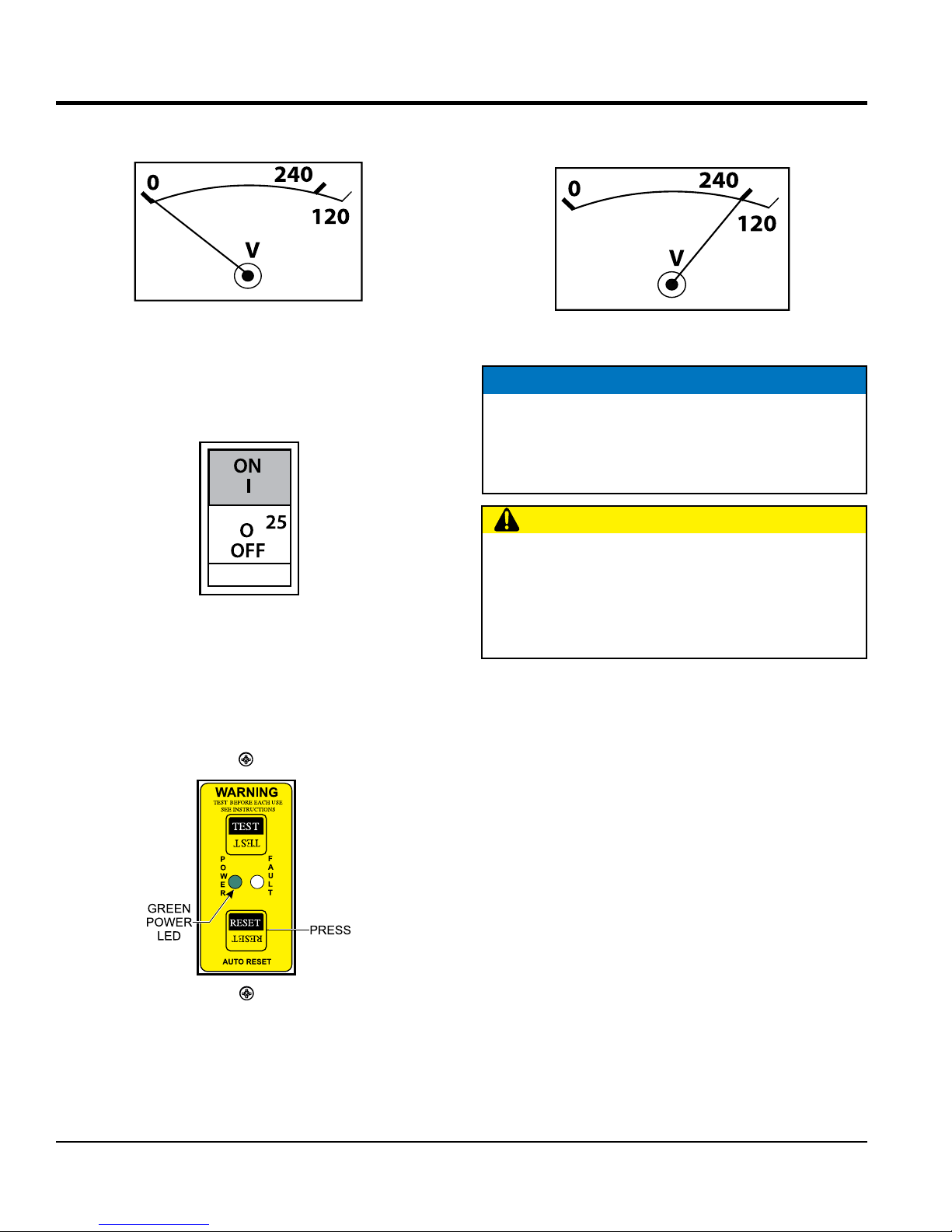
MAINTENANCE
7. Verify that the AC voltmeter (Figure 54) on the weldergenerator reads zero volts.
Figure 54. AC Voltmeter (Zero Volts)
8. Next, place the main circuit breaker, CB1 (Figure 55)
in the ON position.
Figure 55. Main Circuit Breaker (ON)
10. Verify that the AC voltmeter is registering a voltage
reading as indicated by Figure 57.
Figure 57. AC Voltmeter (120/240V)
NOTICE
It is recommended that the GFCI sensing module be
tested when the generator is initially taken out of the
box. Then, the generator should be tested daily at
startup.
CAUTION
The GFCI module is designed to interrupt power when
a ground fault exists to prevent injuries and shock
hazards. DO NOT operate the generator if this test
fails. Consult a qualified electrician for the repair or
replacement of the GFCI module.
9. To restore power, press the RESET button on the
GFCI sensing module (Figure 56) and verify that the
red fault LED turns OFF and the green power LED
should turn ON.
Figure 56. GFCI Sensing Module
(Green LED ON Reset)
PAGE 42 — DA7000SSA3 GENERATOR• OPERATION MANUAL — REV. #0 (02/13/19)
Page 43
GENERATOR WIRING DIAGRAM
DA7000SSA3 GENERATOR• OPERATION MANUAL — REV. #0 (02/13/19) — PAGE 43
Page 44

ENGINE WIRING DIAGRAM
PAGE 44 — DA7000SSA3 GENERATOR• OPERATION MANUAL — REV. #0 (02/13/19)
Page 45
TROUBLESHOOTING (ENGINE AND GENERATOR)
Table 10. Engine and Generator Troubleshooting
SYMPTOM POSSIBLE PROBLEM SOLUTION
Dead Battery? Replace Battery.
Engine fails to start and
starter does not rotate.
Engine fails to start and
starter rotates.
Engine starts "Idle Control
Switch" is in OFF position
and engine remains at low
speed.
Engine starts and "Idle
Control Switch" is in OFF
position. Engine speed rises
and battery discharges too
soon.
Defective Starter Switch? Replace Switch.
Defective Starter? Replace Starter.
Fuse F5 Burned Out? Replace Fuse.
Broken Pre-Heat Circuit? Check Pre-Heat Circuit.
No Fuel? Add Fuel.
Defective Wiring? Check Wiring.
Defective Idle Control Switch? Replace Switch.
Clogged Fuel Strainer? Clean or Replace.
Clogged Air Cleaner? Clean or Replace.
Defective Idle Control Device? Replace.
Disconnected Wiring? Check and Repair Wiring.
Defective Engine Regulator? Replace Regulator.
Defective Wiring? Repair or Replace Wiring.
Engine starts and "Idle
Control Switch" is in OFF
position. Engine speed
rises and engine seems
overloaded.
Engine starts and "Idle
Control Switch" is in OFF
position. Engine speed rises
and engine has abnormal
noise.
Engine starts and "Idle Control
Switch" is in OFF position.
Engine speed rises and
remains at high speed when
Idle Control switch is placed
in the ON position.
Defective Alternator? Repair or Replace Alternator.
Damaged Alternator Bearing? Replace Alternator Bearings.
Loose Engine Parts? Check All Engine Parts For Tightness.
Defective Alternator?
Defective Idle Control Device? Repair or Replace Idle Control Device.
Defective Idle Control Switch? Replace Idle Control Switch.
Defective Solenoid? Replace Solenoid.
Defective Relay? Replace Relay.
Check Alternator for Damaged Bearing or
Loose Clamping Bolts.
DA7000SSA3 GENERATOR• OPERATION MANUAL — REV. #0 (02/13/19) — PAGE 45
Page 46

TROUBLESHOOTING (ENGINE)
Table 11. Engine Troubleshooting
SYMPTOM POSSIBLE PROBLEM SOLUTION
No fuel? Replenish fuel.
Air in the fuel system? Bleed system.
Water in the fuel system? Remove water from fuel tank.
Fuel pipe clogged? Clean fuel pipe.
Fuel filter clogged? Clean or change fuel filter.
Engine does not start.
Starter does not run.
Excessively high viscosity of fuel or
engine oil at low temperature?
Fuel with low cetane number? Use the specified fuel.
Fuel leak due to loose injection pipe
retaining nut?
Incorrect injection timing? Adjust.
Fuel cam shaft worn? Replace.
Injection nozzle clogged? Clean injection nozzle.
Injection pump malfunctioning? Repair or replace.
Seizure of crankshaft, camshaft, piston,
cylinder liner or bearing?
Compression leak from cylinder?
Improper valve timing? Correct or replace timing gear.
Piston ring and liner worn? Replace.
Excessive valve clearance? Adjust.
Battery discharged? Charge battery.
Starter malfunctioning? Repair or replace.
Key switch malfunctioning? Repair or replace.
Use the specified fuel or engine oil.
Tighten nut.
Repair or replace.
Replace head gasket, tighten cylinder
head bolt, glow plug and nozzle holder.
PAGE 46 — DA7000SSA3 GENERATOR• OPERATION MANUAL — REV. #0 (02/13/19)
Wiring disconnected? Connect wiring.
Page 47

TROUBLESHOOTING (ENGINE)
Table 11. Engine Troubleshooting (Continued)
SYMPTOM POSSIBLE PROBLEM SOLUTION
Fuel filter clogged or dirty? Clean or change.
Air cleaner clogged? Clean or change.
Engine revolution is not
smooth.
Either white or
blue exhaust gas is
observed.
Either black or dark
gray exhaust gas is
observed.
Fuel leak due to loose injection pipe retaining
nut?
Injection pump malfunctioning? Repair or replace.
Incorrect nozzle opening pressure? Adjust.
Injection nozzle stuck or clogged? Repair or replace.
Fuel over flow pipe clogged? Clean.
Governor malfunctioning? Repair.
Excessive engine oil? Reduce to the specified level.
Piston ring and liner worn or stuck? Repair or replace.
Incorrect injection timing? Adjust.
Deficient compression? Adjust top clearance.
Overload? Lessen the load.
Low grade fuel used? Use the specified fuel.
Fuel filter clogged? Clean or change.
Air cleaner clogged? Clean or change.
Deficient nozzle injection? Repair or replace the nozzle.
Incorrect injection timing? Adjust.
Tighten nut.
Deficient output.
DA7000SSA3 GENERATOR• OPERATION MANUAL — REV. #0 (02/13/19) — PAGE 47
Engine's moving parts seem to be seizing? Repair or replace.
Uneven fuel injection? Repair or replace the injection pump.
Deficient nozzle injection? Repair or replace the nozzle.
Compression leak?
Replace head gasket, tighten cylinder head
bolt, glow plug and nozzle holder.
Page 48

OPERATION MANUAL
HERE’S HOW TO GET HELP
© COPYRIGHT 2019, MULTIQUIP INC.
Multiquip Inc
the MQ logo are registered trademarks of Multiquip Inc. and may not be used, reproduced, or altered without written permission. All other trademarks are the property
of their respective owners and used with permission.
This manual
The information and specifi cations included in this publication were in effect at the time of approval for printing. Illustrations, descriptions, references and technical data contained in
this manual are for guidance only and may not be considered as binding. Multiquip Inc. reserves the right to discontinue or change specifi cations, design or the information published
in this publication at any time without notice and without incurring any obligations.
DENYO CO., LTD, JAPAN
PLEASE HAVE THE MODEL AND SERIAL
NUMBER ON-HAND WHEN CALLING
UNITED STATES
Multiquip Corporate Office MQ Parts Department
18910 Wilmington Ave.
Carson, CA 90746
Contact: mq@multiquip.com
Service Department Warranty Department
800-421-1244
310-537-3700
Technical Assistance
800-478-1244 Fax: 310-943-2238
CANADA
Multiquip
4110 Industriel Boul.
Laval, Quebec, Canada H7L 6V3
Contact: infocanada@multiquip.com
Tel. (800) 421-1244
Fax (310) 537-3927
Tel: (450) 625-2244
Tel: (877) 963-4411
Fax: (450) 625-8664
800-427-1244
310-537-3700
800-421-1244
310-537-3700
UNITED KINGDOM
Multiquip (UK) Limited Head Office
Unit 2, Northpoint Industrial Estate,
Globe Lane,
Dukinfield, Cheshire SK16 4UJ
Contact: sales@multiquip.co.uk
Fax: 800-672-7877
Fax: 310-943-2249
Tel: 0161 339 2223
Fax: 0161 339 3226
,
MUST accompany the equipment at all times. This manual is considered a permanent part of the equipment and should remain with the unit if resold.
Manufactured for
Multiquip Inc.
Your Local Dealer is:
by
 Loading...