

MQ Multiquip MVC82VHW, MVC82VH Parts Manual

OPERATION AND PARTS MANUAL
THIS MANUAL MUST ACCOMPANY THE EQUIPMENT AT ALL TIMES.
Discount-Equipment.com
SERIES
MODEL MVC82VH/VHW
ONE-WAY PLATE COMPACTOR
(HONDA GX160U1SM12, GX160U1SMX4,
GX160UT2QMXC, GX160UT2SMXC and
GX160UT2SCM GASOLINE ENGINES)
Revision #3 (12/21/17)
www.discount-equipment.com

Discount-Equipment.com is your online resource for commercial and industrial
Discount-Equipment.com
quality parts and equipment sales.
Locations:
Florida (West Palm Beach): 561-964-4949
Outside Florida TOLL FREE: 877-690-3101
Need parts? Check out our website at www.discount-equipment.com
Can’t find what you need?
Click on this link: http://www.discount-equipment.com/category/5443-parts/ and fill out
the request form.
Please have the machine model and serial number available in order to help us get
you the correct parts. One of our experienced staff members will get back to you with
a quote for the right part that your machine needs.
We sell worldwide for the brands: Genie, Terex, JLG, MultiQuip, Mayco, Toro/Stone,
Diamond Products, Magnum, Airman, Mustang, Power Blanket, Nifty Lift, Atlas Copco,
Chicago Pneumatic,
Tsurumi, Husquvarna/Target, Whiteman-Concrete/Mortar, Stow-Concrete/Mortar, Baldor,
Wacker, Sakai, Snorkel, Upright, Mi-T-M, Sullair, Neal, Basic, Dynapac, MBW, Weber,
Bartell, Bennar Newman, Haulotte, Ditch Runner, Blaw-Knox, Himoinsa, Best, Buddy,
Crown, Edco, Wyco, Bomag, Laymor, Terremite, Barreto, EZ Trench, Takeuchi, Basic, Bil-
Jax, Curtis, Gehl, Heli, Honda, ICS/PowerGrit, Puckett,
Clipper, MMD, Koshin, Rice, Gorman Rupp, CH&E, Cat Pumps, Comet, General Pump,
Giant,AMida, Coleman, NAC, Gradall, Square Shooter, Kent, Stanley, Tamco, Toku, Hatz,
Kohler, Robin, Wisconsin, Northrock, Oztec, Toker TK, Rol-Air, Small Line, Wanco, Yanmar
Allmand Brothers, Essick, Miller Spreader, Skyjack, Lull, Skytrak,
Waldon, ASV, IHI, Partner, Imer,
PROPOSITION 65 WARNING
Discount-Equipment.com
PAGE 2 —MVC82VH/VHW PLATE COMPACTOR • OPERATION AND PARTS MANUAL — REV. #3 (12/21/17)

TABLE OF CONTENTS
Discount-Equipment.com
MVC82VH/VHW
Plate Compactor
Proposition 65 Warning ........................................... 2
Table Of Contents .................................................... 4
Parts Ordering Procedures ...................................... 5
Safety Information .............................................. 6-10
Specifications ........................................................ 11
Noise And Vibration Emissions .............................. 12
Dimensions ............................................................ 13
General Information ............................................... 14
Components .......................................................... 15
Basic Engine .......................................................... 16
Inspection ......................................................... 17-19
Operation .......................................................... 20-21
Maintenance ..................................................... 22-27
Troubleshooting (Engine) .................................. 28-29
Troubleshooting (Compactor) ................................ 30
Explanation Of Code In Remarks Column............. 32
Suggested Spare Parts ......................................... 33
HONDA GX160 Series Engines
Cylinder Head Assembly .................................. 44-45
Cylinder Barrel Assembly ................................. 46-47
Crankcase Cover Assembly ............................. 48-49
Crankshaft Assembly ........................................ 50-51
Piston Assembly ............................................... 52-53
Camshaft Assembly .......................................... 54-55
Recoil Starter Assembly ................................... 56-57
Fan Cover Assembly......................................... 58-59
Carburetor Assembly ........................................ 60-61
Air Cleaner Assembly (Standard) ..................... 62-63
Air Cleaner Assembly (Cylone Type 1) ................ 64-65
Air Cleaner Assembly (Cyclone Type 2) ........... 66-67
Muffler Assembly .............................................. 68-69
Fuel Tank Assembly ..........................................70-71
Flywheel Assembly ........................................... 72-73
Ignition Coil Assembly ..........................................74-75
Control Assembly .................................................76-77
Decals Assembly .................................................78-79
Compactor Component
Drawings
Nameplate And Decals ..................................... 34-35
Body Assembly ................................................. 36-39
Vibrator Assembly ............................................ 40-41
Water Tank Assembly (MVC82VHW Only) ....... 42-43
Terms And Conditions Of Sale — Parts ................ 80
NOTICE
Specifications and part numbers are subject to change
without notice.
PAGE 4 —MVC82VH/VHW PLATE COMPACTOR • OPERATION AND PARTS MANUAL — REV. #3 (12/21/17)
SAFETY INFORMATION
Do not operate or service the equipment before reading
the entire manual. Safety precautions should be followed
at all times when operating this equipment.
Failure to read and understand the safety
messages and operating instructions could
result in injury to yourself and others.
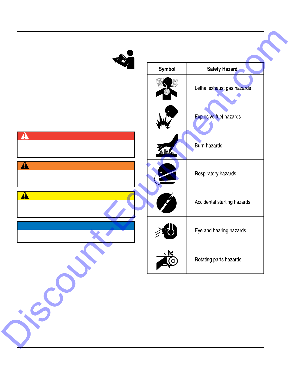
SAFETY MESSAGES
The four safety messages shown below will inform you
about potential hazards that could injure you or others. The
safety messages specifi cally address the level of exposure
to the operator and are preceded by one of four words:
DANGER, WARNING, CAUTION
SAFETY SYMBOLS
Potential hazards associated with the operation of this
equipment will be referenced with hazard symbols which
may appear throughout this manual in conjunction with
Discount-Equipment.com
safety messages.
DANGER
Indicates a hazardous situation which, if not avoided,
WILL result in DEATH or SERIOUS INJURY.
WARNING
Indicates a hazardous situation which, if not avoided,
COULD result in DEATH or SERIOUS INJURY.
CAUTION
Indicates a hazardous situation which, if not avoided,
COULD result in MINOR or MODERATE INJURY.
or NOTICE.
NOTICE
Addresses practices not related to personal injury.
PAGE 6 —MVC82VH/VHW PLATE COMPACTOR • OPERATION AND PARTS MANUAL — REV. #3 (12/21/17)
GENERAL SAFETY
NOTICE
This equipment should only be operated by trained and
Whenever necessary, replace nameplate, operation and
Manufacturer does not assume responsibility for any
accident due to equipment modifi cations. Unauthorized
use accessories or attachments that are not
recommended by Multiquip for this equipment. Damage
keep
Also, know the phone numbers
fi re department.
This information will be invaluable in the case of an
Discount-Equipment.com
SAFETY INFORMATION
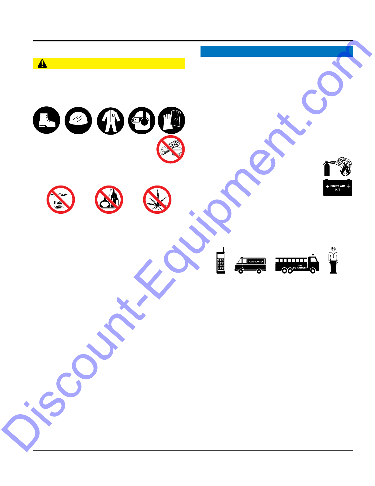
CAUTION
NEVER operate this equipment without proper protective
clothing, shatterproof glasses, respiratory protection,
hearing protection, steel-toed boots and other protective
devices required by the job or city and state regulations.
NEVER operate this equipment when not
feeling well due to fatigue, illness or when
under medication.
NEVER operate this equipment under the infl uence of
drugs or alcohol.
ALWAYS check the equipment for loosened threads or
bolts before starting.
DO NOT use the equipment for any purpose other than
its intended purposes or applications.
ALWAYS clear the work area of any debris, tools, etc.
that would constitute a hazard while the equipment is
in operation.
qualifi ed personnel 18 years of age and older.
safety decals when they become diffi cult read.
equipment modifi cation will void all warranties.
NEVER
to the equipment and/or injury to user may result.
ALWAYS know the location of the nearest
fi re extinguisher.
ALWAYS know the location of the nearest
fi rst aid kit.
ALWAYS know the location of the nearest phone or
a phone on the job site.
of the nearest ambulance, doctor and
emergency.
MVC82VH/VHW PLATE COMPACTOR • OPERATION AND PARTS MANUAL — REV. #3 (12/21/17) — PAGE 7
SAFETY INFORMATION
COMPACTOR SAFETY
ENGINE SAFETY
place hands or fingers inside engine
operate the engine with heat shields or
engine is hot. High pressure boiling water will gush out
of the radiator and severely scald any persons in the
remove the engine oil drain plug while the
engine is hot. Hot oil will gush out of the oil tank and
severely scald any persons in the general area of the
run engine without an air fi lter or with a dirty air
fi lter. Severe engine damage may occur. Service air fi lter
tip the engine to extreme angles during lifting as
it may cause oil to gravitate into the cylinder head, making
Discount-Equipment.com
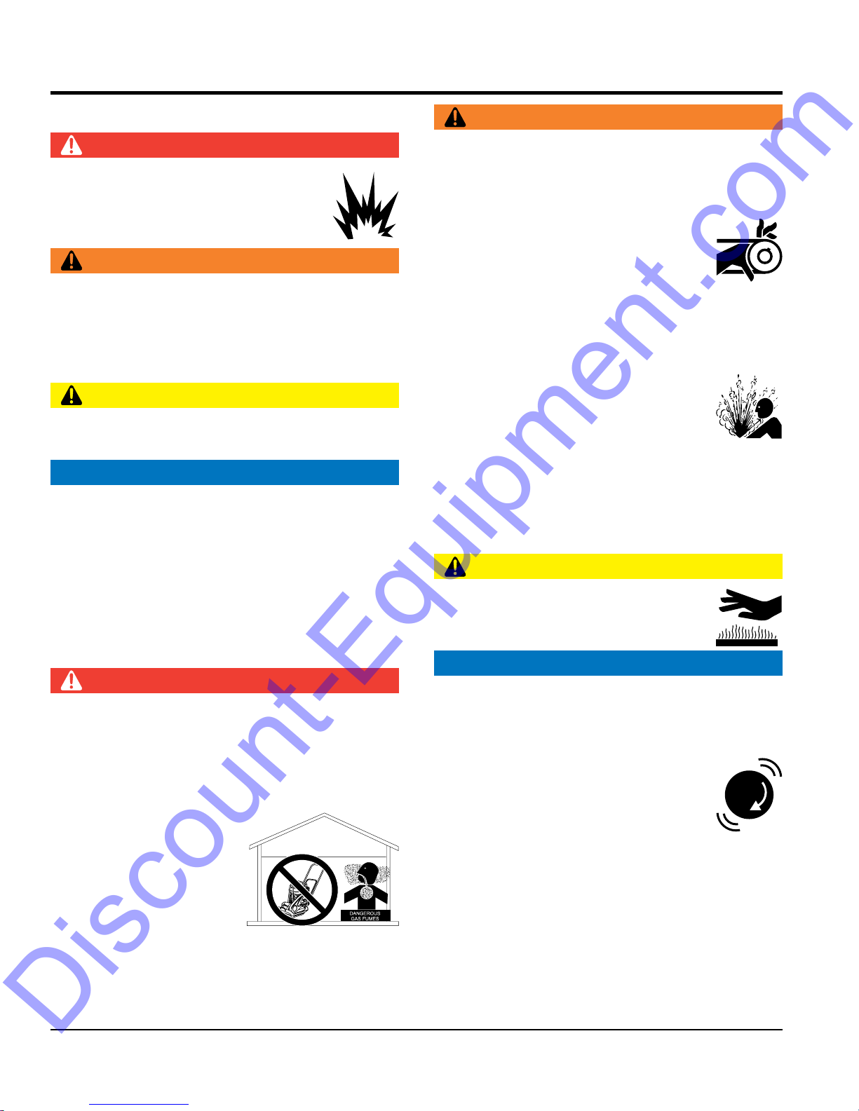
WARNING
DANGER
NEVER operate the equipment in an explosive
atmosphere or near combustible materials. An
explosion or fi re could result causing severe
bodily harm or even death.
WARNING
NEVER disconnect any emergency or safety devices.
These devices are intended for operator safety.
Disconnection of these devices can cause severe injury,
bodily harm or even death. Disconnection of any of these
devices will void all warranties.
CAUTION
NEVER lubricate components or attempt service on a
running machine.
NOTICE
ALWAYS keep the machine in proper running condition.
Fix damage to machine and replace any broken parts
immediately.
ALWAYS store equipment properly when it is not being
used. Equipment should be stored in a clean, dry location
out of the reach of children and unauthorized personnel.
DO NOT
compartment when engine is running.
NEVER
guards removed.
Keep fi ngers, hands hair and clothing away
from all moving parts to prevent injury.
DO NOT remove the radiator cap while the
general area of the compactor.
DO NOT remove the coolant drain plug
while the engine is hot. Hot coolant will
gush out of the coolant tank and severely
scald any persons in the general area of
the compactor.
DO NOT
compactor.
CAUTION
NEVER touch the hot exhaust manifold,
muffl er or cylinder. Allow these parts to cool
before servicing equipment.
DANGER
The engine fuel exhaust gases contain poisonous carbon
monoxide. This gas is colorless and odorless, and can
cause death if inhaled.
The engine of this equipment requires an adequate
free fl ow of cooling air. NEVER operate this equipment
in any enclosed or narrow
area where free fl ow of the
air is restricted. If the air
fl ow is restricted it will cause
injury to people and property
and serious damage to the
equipment or engine.
PAGE 8 —MVC82VH/VHW PLATE COMPACTOR • OPERATION AND PARTS MANUAL — REV. #3 (12/21/17)
NOTICE
NEVER
frequently to prevent engine malfunction.
NEVER tamper with the factory settings
of the engine or engine governor. Damage
to the engine or equipment can result
if operating in speed ranges above the
maximum allowable.
NEVER
the engine start diffi cult.
SAFETY INFORMATION
FUEL SAFETY
BATTERY SAFETY (ELECTRIC START ONLY)
drop the battery. There is a possibility that the
keep the battery charged. If the battery is not
charge battery if frozen. Battery can explode.
When frozen, warm the battery to at least 61°F (16°C).
recharge the battery in a well-ventilated
environment to avoid the risk of a dangerous concentration
If the battery liquid (dilute sulfuric acid) comes into
, rinse eyes immediately with plenty
of water and contact the nearest doctor or hospital to
NEGATIVE battery terminal
keep battery cables in good working condition.
Discount-Equipment.com
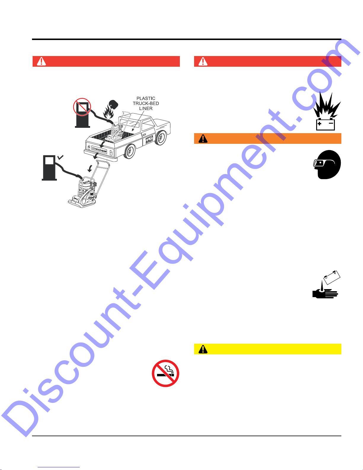
DO NOT add fuel to equipment if it is placed inside truck
DO NOT start the engine near spilled fuel or combustible
DANGER
bed with plastic liner. Possibility exists of explosion or
fi re due to static electricity.
FUEL
FUEL
fl uids. Diesel fuel is extremely fl ammable and its vapors
can cause an explosion if ignited.
DANGER
DO NOT
battery will explode.
DO NOT expose the battery to open fl ames,
sparks, cigarettes, etc. The battery contains
combustible gases and liquids. If these
gases and liquids come into contact with a
fl ame or spark, an explosion could occur.
WARNING
ALWAYS wear safety glasses when
handling the battery to avoid eye irritation.
The battery contains acids that can cause
injury to the eyes and skin.
Use well-insulated gloves when picking up
the battery.
ALWAYS
charged, combustible gas will build up.
DO NOT
ALWAYS refuel in a well-ventilated area, away from
sparks and open fl ames.
ALWAYS use extreme caution when working with
fl ammable liquids.
DO NOT fi ll the fuel tank while the engine is running
or hot.
DO NOT overfi ll tank, since spilled fuel could ignite if it
comes into contact with hot engine parts or sparks from
the ignition system.
Store fuel in appropriate containers, in well-ventilated
areas and away from sparks and fl ames.
NEVER use fuel as a cleaning agent.
DO NOT smoke around or near the
equipment. Fire or explosion could result
from fuel vapors or if fuel is spilled on a
hot engine.
ALWAYS
of combustible gases.
If the battery liquid (dilute sulfuric acid)
comes into contact with clothing or skin,
rinse skin or clothing immediately with
plenty of water.
contact with eyes
seek medical attention.
CAUTION
ALWAYS disconnect the
before performing service on the equipment.
ALWAYS
Repair or replace all worn cables.
MVC82VH/VHW PLATE COMPACTOR • OPERATION AND PARTS MANUAL — REV. #3 (12/21/17) — PAGE 9
TRANSPORTING SAFETY
CAUTION
ENVIRONMENTAL SAFETY
Discount-Equipment.com
NEVER allow any person or animal to stand underneath
the equipment while lifting.
NOTICE
Before lifting, make sure that the equipment parts (hook
and vibration insulator) are not damaged and screws are
not loose or missing.
Always make sure crane or lifi tng device has been
properly secured to the lifting bail (hook) of the
equipment.
ALWAYS shutdown engine before transporting.
NEVER lift the equipment while the engine is running.
Tighten fuel tank cap securely and close fuel cock to
prevent fuel from spilling.
SAFETY INFORMATION
Use adequate lifting cable (wire or rope) of suffi cient
strength.
Use one point suspension hook and lift straight
upwards.
DO NOT lift machine to unnecessary heights.
ALWAYS tie down equipment during transport by
securing the equipment with rope.
NOTICE
Dispose of hazardous waste properly.
Examples of potentially hazardous waste
are used motor oil, fuel and fuel fi lters.
DO NOT use food or plastic containers to dispose of
hazardous waste.
DO NOT pour waste, oil or fuel directly onto the ground,
down a drain or into any water source.
PAGE 10 —MVC82VH/VHW PLATE COMPACTOR • OPERATION AND PARTS MANUAL — REV. #3 (12/21/17)
SPECIFICATIONS
Discount-Equipment.com
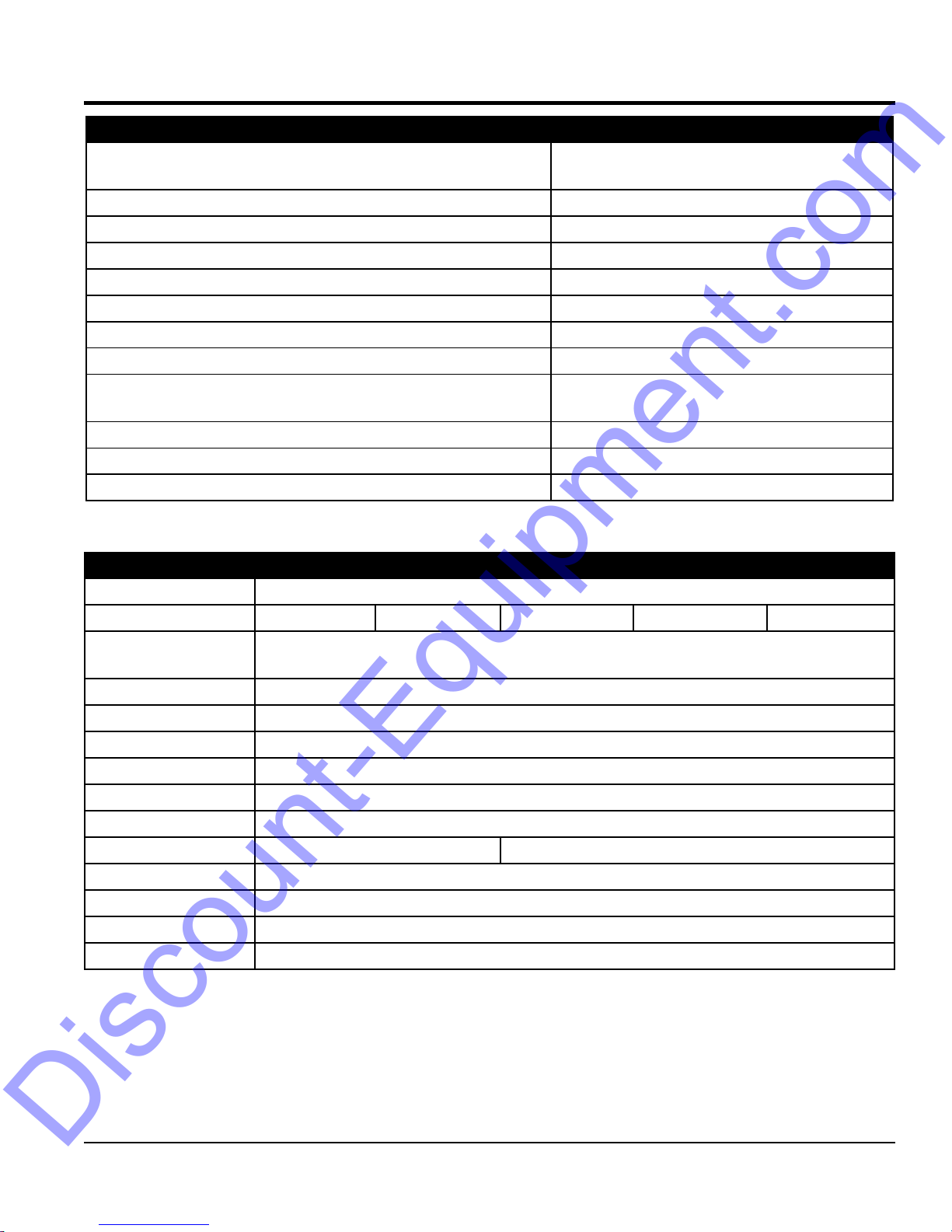
Table 1. Compactor Specifications
Models
Handle HAV (Center Handle)
Centrifugal Force 3080 lbf. (13.7 kN)
Number of Vibrations 5,600 vibrations/min (93 Hz)
Traveling Speed 72 ft./min (22 meters/min)
Plate Size (LxW)
Length (Including Handle)
Height (Including Handle)
Operating Weight (VH)
Operating Weight (VHW)
Water Tank Capacity (VHW Model Only) 11.5 qt. (10.9 liters)
Max. Area Of Compaction
Vibrator Oil Capacity
22.4 x 17.7 in. (570 x 450 mm)
7,262 sq. ft./hr. (675 sq. m/hr)
MVC82VH
MVC82VHW
38.2 in. (970 mm)
22.4 in. (570 mm)
175 lbs. (79 kg.)
181 lbs. (82 kg.)
0.15 qt. (0.14 liters)
Table 2. Engine Specifications
Make Honda
Model GX160U1SM12 GX160U1SMX4 GX160UT2QMXC GX160UT2SMXC GX160UT2SCM
Type
Bore X Stroke 2.7 in. x 1.8 in. (68 mm x 45 mm)
Displacement 163 cc (9.9 cu. in)
Max Output 4.8 H.P./3600 R.P.M.
Fuel Tank Capacity
Fuel
Lube Oil Capacity
Air Cleaner Dual Filter Element Cyclone Filter Element
Speed Control Method
Starting Method Recoil Start
Dimension (L x W x H)
Dry Net Weight
Air-cooled 4 stroke, Single Cylinder, OHV
Horizontal Shaft Gasoline Engine
Approx. 0.95 U.S. gallons (3.6 liters)
Unleaded Automobile Gasoline
0.63 qts (0.60 liters)
Centrifugal Fly-weight Type
12.0 x 14.2 x 13.2 in. (304 x 362 x 335 mm)
23.1 lbs (10.48 Kg.)
MVC82VH/VHW PLATE COMPACTOR • OPERATION AND PARTS MANUAL — REV. #3 (12/21/17) — PAGE 11

NOISE AND VIBRATION EMISSIONS
Discount-Equipment.com
Table 3. Noise and Vibration Emissions
Measured Sound Power Level in dB(A) 101
Guaranteed Sound Power Level in dB(A) 105
Guaranteed Sound Pressure Level at Operator Station in dB(A) 90
Hand-Arm Vibration in m/s
NOTES:
1. Products are tested for sound pressure level in accordance with European Directives 2000/14/EC and 2005/88/EC, relating to Noise Emission
in the Environment by equipment for use outdoors.
2. Products are tested for hand/arm vibration (HAV) level in accordance with European Directives 2002/44/EC and EN500-4 and ISO 5349-1:2001,
ISO 5349-2:2001.
2
3.5
PAGE 12 —MVC82VH/VHW PLATE COMPACTOR • OPERATION AND PARTS MANUAL — REV. #3 (12/21/17)
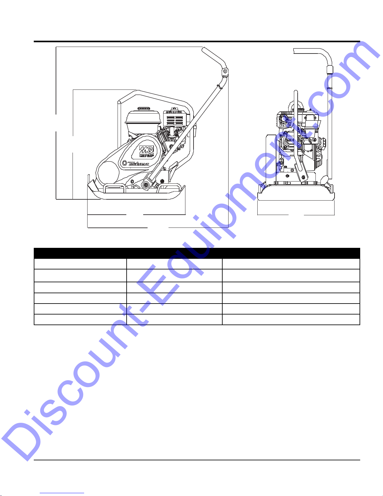
C
B
A
Discount-Equipment.com
DIMENSIONS
D
Table 4. Dimensions
Reference Letter Description Dimension
A Length (including handle) 38.2 inches (970 mm)
B Height (without handle) 22.4 inches (570 mm)
C Height (including handle) 38 inches (965 mm)
D Plate Length 22.4 inches (570 mm)
E Plate Width 17.7 inches (450 mm)
E
MVC82VH/VHW PLATE COMPACTOR • OPERATION AND PARTS MANUAL — REV. #3 (12/21/17) — PAGE 13

GENERAL INFORMATION
Discount-Equipment.com
DEFINITION OF PLATE COMPACTOR
The Mikasa MVC82VH/VHW is a walk-behind, one-way
plate compactor designed for the compaction of sand,
mixed soils and asphalt. This plate compactor is a powerful
compacting tool capable of applying a tremendous force in
consecutive high frequency vibrations to a soil surface. Its
applications include compacting for road, embankments
and reservoirs as well as backfilling for gas pipelines, water
pipelines and cable installation work.
VIBRATORY PLATES
The vibratory plates of the MVC82VH/VHW produce low
amplitude high frequency vibrations, designed to compact
granular soils and asphalt.
The resulting vibrations cause forward motion. The engine
and handle are vibration-isolated from the vibrating plate.
FREQUENCY/SPEED
The compactor's vibrating plate has a frequency range of
5600 vpm (vibrations per minute). The travel speed of the
compactor is approximately 72 feet/minute (22 meters/
minute).
ENGINE
These plate compactors are equipped with a Honda GX160
series air cooled, 4-cycle gasoline engine. Reference
Table 2 for complete specifications. The engine drives an
eccentric weight at a high speed to develop a compaction
force.
CONTROLS
Before starting the plate compactor, identify and understand
the function of all the controls and components.
PAGE 14 —MVC82VH/VHW PLATE COMPACTOR • OPERATION AND PARTS MANUAL — REV. #3 (12/21/17)
9
(MVC8
Discount-Equipment.com
COMPONENTS
1
10
4
3
2
WATER TANK
2VHW ONLY)
8
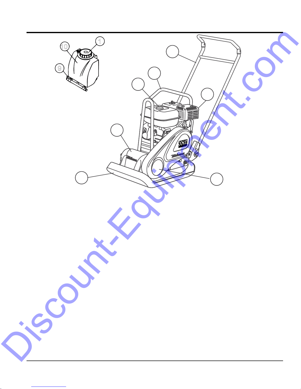
Figure 1. Plate Compactor Components
Figure 1 shows the location of the basic controls and
components of the MVC82VH/VHW Plate Compactor. The
function of each control is described below:
1. Water Tank Cap (VHW Only) — Remove this cap to
add water to the water tank.
2. Fuel Tank Cap — Remove this cap to add unleaded
gasoline to the fuel tank.
3. Lifting Bale — When lifting of the compactor is
required either by forklift, crane, etc., tie rope or chain
around this lifting point.
4. Handle Bar — When operating the compactor use this
handle bar to maneuver the compactor.
5. Gasoline Engine — This plate compactor uses a
HONDA 4.8 HP GX160 series, air-cooled 4 stroke
gasoline engine. Refer to the owner's manual for engine
information.
5
67
6. Belt Cover — Remove this cover to gain access to the
V-belts. NEVER run the compactor without the V-belt
cover. If the V-belt cover is not installed, the possibility
exists that your hand may get caught between the V-belt
and clutch, causing serious injury and bodily harm.
7. Vibrating Plate — A flat, open plate made of durable
cast iron construction used in the compacting of soil.
8. Vibration Case — Encloses the eccentric, gears and
counter weights.
9. Water Shut-Off Valve (VHW only) — Turn this valve
downward to let water flow from the water tank to the
water tube.
10. Water Tank (VHW only) — Holds 13.8 quarts of water
(removable, no tools required).
MVC82VH/VHW PLATE COMPACTOR • OPERATION AND PARTS MANUAL — REV. #3 (12/21/17) — PAGE 15
BASIC ENGINE
Discount-Equipment.com
11
STANDARD AIR CLEANER
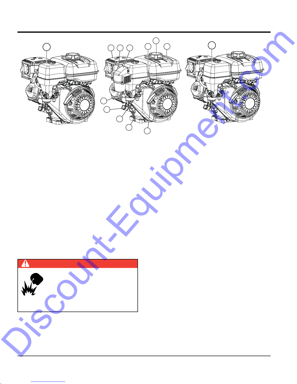
The engine (Figure 2) must be checked for proper
lubrication and filled with fuel prior to operation. Refer to the
manufacturer's engine manual for instructions and details
of operation and servicing.
1. Throttle Lever – Used to adjust engine RPM speed.
For normal operation this lever should always be placed
in the RUN position.
2. Fuel Cap – Remove this cap to add unleaded gasoline
to the fuel tank. Fill with unleaded gasoline.
3. Fuel Tank – Refer to Table 2 for fuel tank capacity.
Make sure cap is tightened securely. DO NOT over
fill. For additional information refer to Honda engine
owner's manual.
DANGER
Add fuel to the tank only when the engine
is stopped and has had an opportunity to
cool down. In the event of a fuel spill, DO
NOT attempt to start the engine until the
fuel residue has been completely wiped up
and the area surrounding the engine is dry.
9
8
7
TYPE 1 CYCLONE AIR CLEANER
Figure 2. Engine Components
10
6
11
5
2
1
4
4. Recoil Starter (Pull Rope) – Manual-starting method.
5. Oil Drain Plug – Remove this plug to remove oil from
6. Fuel Valve Lever – OPEN to let fuel flow, CLOSE to
7. Dipstick/Oil Filler Cap – Remove this cap to determine
8. Choke Lever – Used in the starting of a cold engine,
9. Muffler – Used to reduce noise and emissions. NEVER
10. Spark Plug – Provides spark to the ignition system.
11. Air Cleaner – Prevents dirt and other debris from
3
Pull the starter grip until resistance is felt, then pull
briskly and smoothly.
the engine's crankcase.
stop the flow of fuel.
if the engine oil is low. Add oil through this filler port as
recommended in (Table 5).
or in cold weather conditions. The choke enriches the
fuel mixture.
touch when hot!
Set spark plug gap according to engine manufacturer's
instructions. Clean spark plug once a week.
entering the fuel system. Remove wing-nut on top of air
filter cover to gain access to filter element. Reference
the maintenance section in this manual for servicing.
11
TYPE 2 CYCLONE AIR CLEANER
PAGE 16 —MVC82VH/VHW PLATE COMPACTOR • OPERATION AND PARTS MANUAL — REV. #3 (12/21/17)
INSPECTION
WATER
TANK
WATER
SOURCE
Discount-Equipment.com
BEFORE STARTING
1. Read all safety instructions at the beginning of manual.
2. Clean the compactor, removing dirt and dust,
particularly the engine cooling air inlet, carburetor and
air cleaner.
3. Check the air filter for dirt and dust. If air filter is dirty,
replace air filter with a new one as required.
4. Check carburetor for external dirt and dust. Clean with
dry compressed air.
5. Check fastening nuts and bolts for tightness.
ENGINE OIL CHECK
1. To check the engine oil level, place the compactor on
secure level ground with the engine stopped.
2. Remove the dipstick from the engine oil filler hole
(Figure 3) and wipe clean.
WARNING
Adding fuel to the tank should be
accomplished only when the engine is
stopped and has had an opportunity to
cool down. In the event of a fuel spill, DO
NOT attempt to start the engine until the
fuel residue has been completely wiped up, and the
area surrounding the engine is dry.
FUEL CHECK
1. Visually inspect (Figure 5) to see if fuel level is low. If
fuel is low, replenish with unleaded fuel.
FUEL
CAP
DIPSTICK
Figure 3. Engine Oil Dipstick Removal
3. Insert and remove the dipstick without screwing it into
the filler neck. Check the oil level shown on the dipstick.
4. If the oil level is low (Figure 4), fill to the edge of the
oil filler hole with the recommended oil type as listed
in Table 5. Refer to Table 2 for maximum engine oil
capacity.
UPPER LIMIT
LOWER LIMIT
Figure 4. Engine Oil Dipstick (Oil Level)
Table 5. Oil Type
Season Temperature Oil Type
Summer 25°C or Higher SAE 10W-30
Spring/Fall 25°C~10°C SAE 10W-30/20
Winter 0°C or Lower SAE 10W-10
Figure 5. Fuel Check
2. When refueling, be sure to use a strainer for filtration.
DO NOT top-off fuel. Wipe up any spilled fuel
immediately.
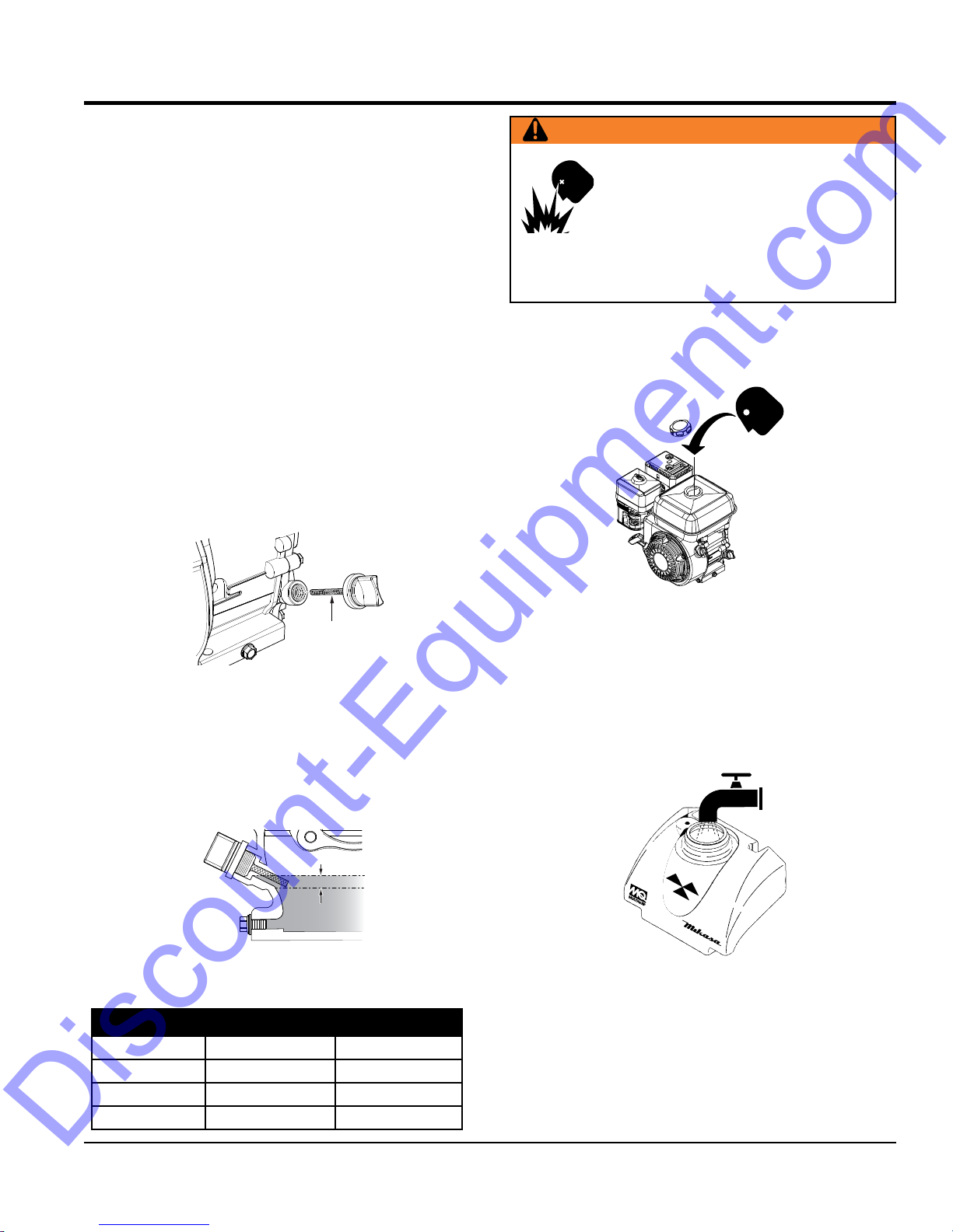
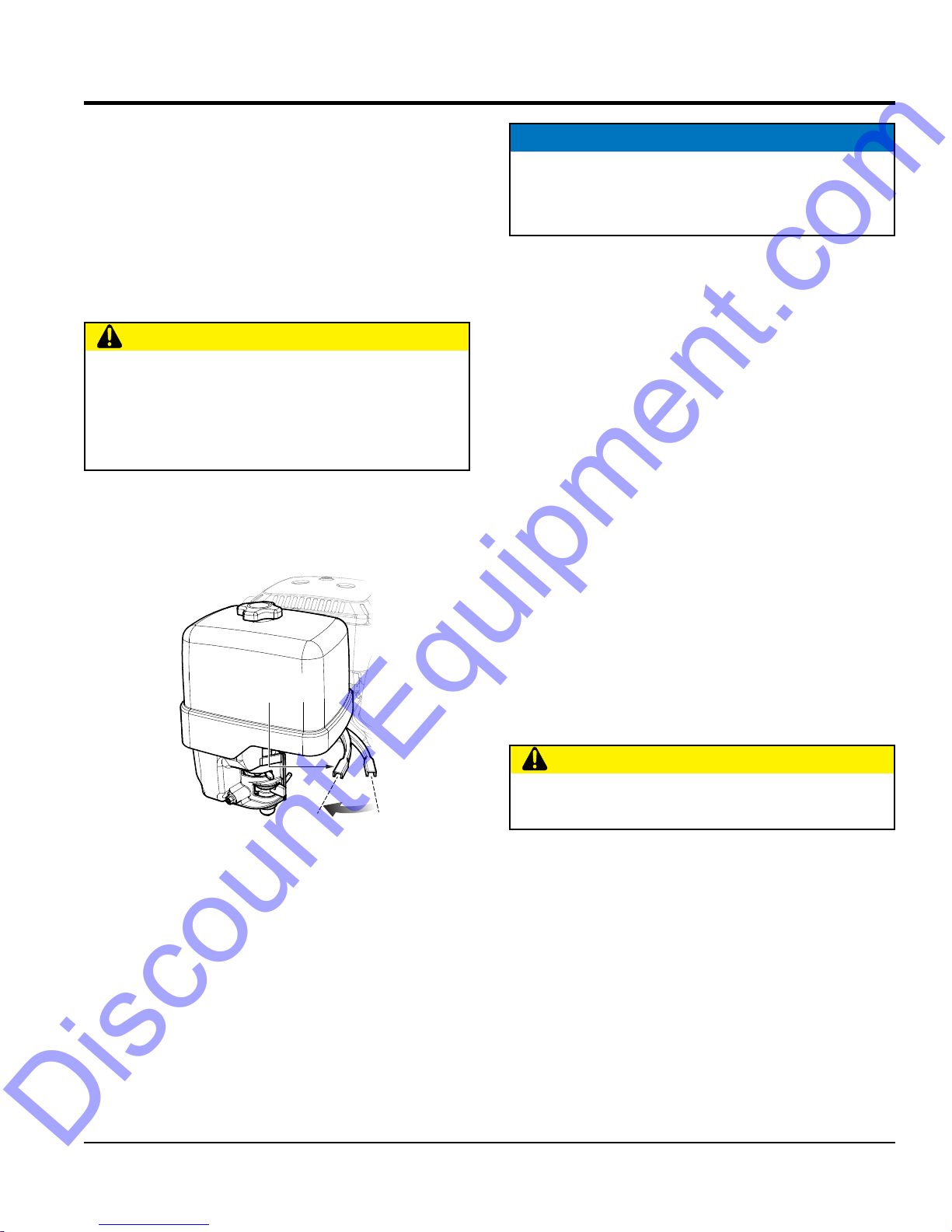
Water Tank (Option)
If your unit is equipped with a water tank (Figure 6) and
your application requires water, fill water tank.
Figure 6. Water Tank Filling
MVC82VH/VHW PLATE COMPACTOR • OPERATION AND PARTS MANUAL — REV. #3 (12/21/17) — PAGE 17
INSPECTION
CRACKS
WEAR
CLUTCH
PULLEY
Discount-Equipment.com
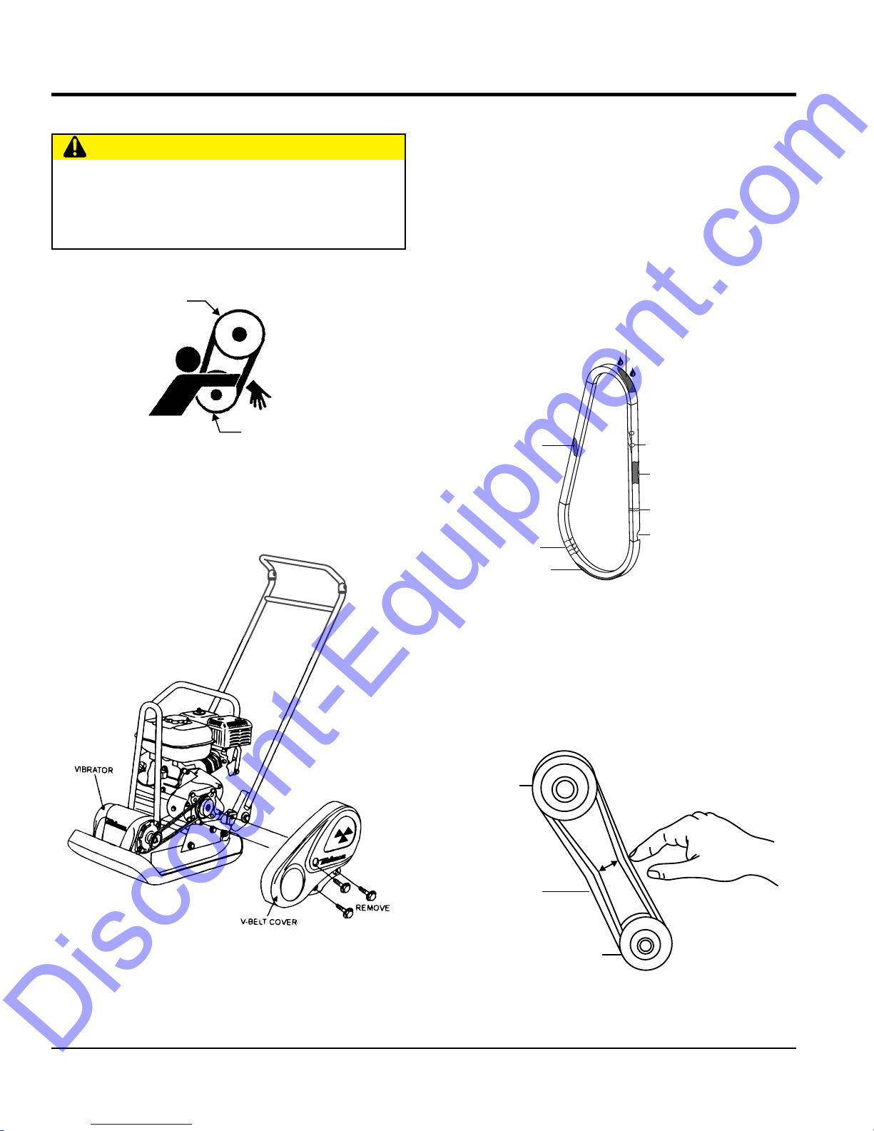
V-BELT CHECK
CAUTION
NEVER attempt to check the V-belt with the engine
running. Severe injury can occur if your hand (Figure 7)
gets caught between the V-belt and the clutch. Always
use safety gloves.
CLUTCH
PULLEY
VIBRATOR
PULLEY
Figure 7. V-Belt Hazard
1. To check the V-belt tension, remove the three bolts that
secure the belt cover to the frame as shown in Figure 8.
V-BELT INSPECTION
Visually examine the V-belt (Figure 9) and determine if it
is full of tiny cracks, frayed, has pieces of rubber missing,
is peeling or otherwise damaged.
Also, examine the belt and determine if it is oil soaked or
"glazed " (hard shiny appearance on the sides of the belt).
Either of these two conditions can cause the belt to run hot,
which can weaken it and increase the danger of it breaking.
If the V-belt exhibits any of the referenced wear conditions
replace the V-belt immediately
OIL SOAKED
GLAZED
CORD FAILURE
WORN BACK
COVER
BROKEN
MISSING RUBBER
Figure 8. V-Belt Cover Removal
SIDEWALL
Figure 9. Drive Belt Inspection
V-BELT TENSION
1. The V-belt tension is proper if the V-belt bends
10 to 15 mm (Figure 10) when depressed with finger
at midway between the clutch and vibrator pulleys.
CORRECT V-BELT
TENSION 10-15 MM
WHEN DEPRESSED
AS SHOWN.
V-BELT
VIBRATOR
PULLEY
PAGE 18 —MVC82VH/VHW PLATE COMPACTOR • OPERATION AND PARTS MANUAL — REV. #3 (12/21/17)
Figure 10. V-Belt Tension
2. A loose V-belt will decrease the power transmission
Discount-Equipment.com
output causing reduced compaction and premature
wear of the belt.
3. If the V-belt becomes worn or loose, replace it.
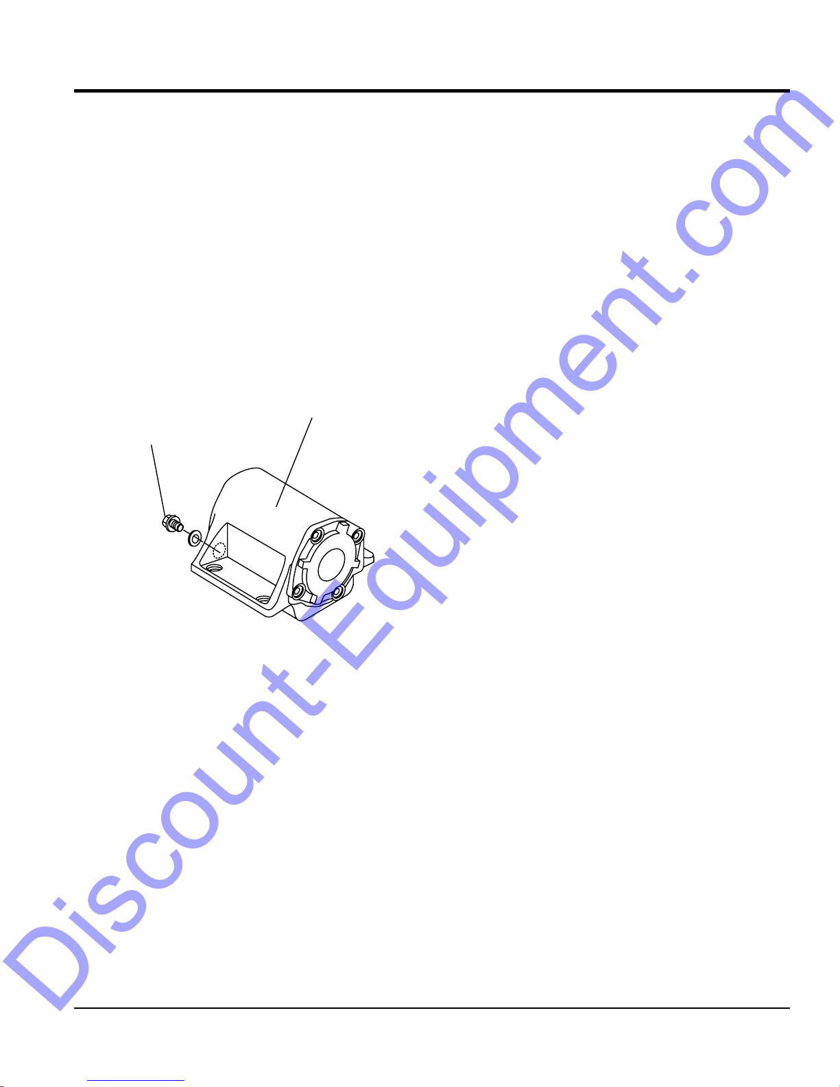
VIBRATOR OIL CHECK
1. Place the plate compactor horizontally on a flat surface.
Make sure the compactor is level when checking the
oil in the vibrator assembly.
2. Check vibrator oil level by removing the oil plug
(vibrator oil gauge) as shown in Figure 11. The oil level
should be up to the oil plug. The vibrator holds 140 cc
(approximately 0.3 pint). IMPORTANT, if oil is required,
replace using only SAE10W-30 motor oil.
VIBRATOR
OIL PLUG
INSPECTION
Figure 11. Vibrator Oil Plug
MVC82VH/VHW PLATE COMPACTOR • OPERATION AND PARTS MANUAL — REV. #3 (12/21/17) — PAGE 19
OPERATION
STARTER GRIP
Discount-Equipment.com
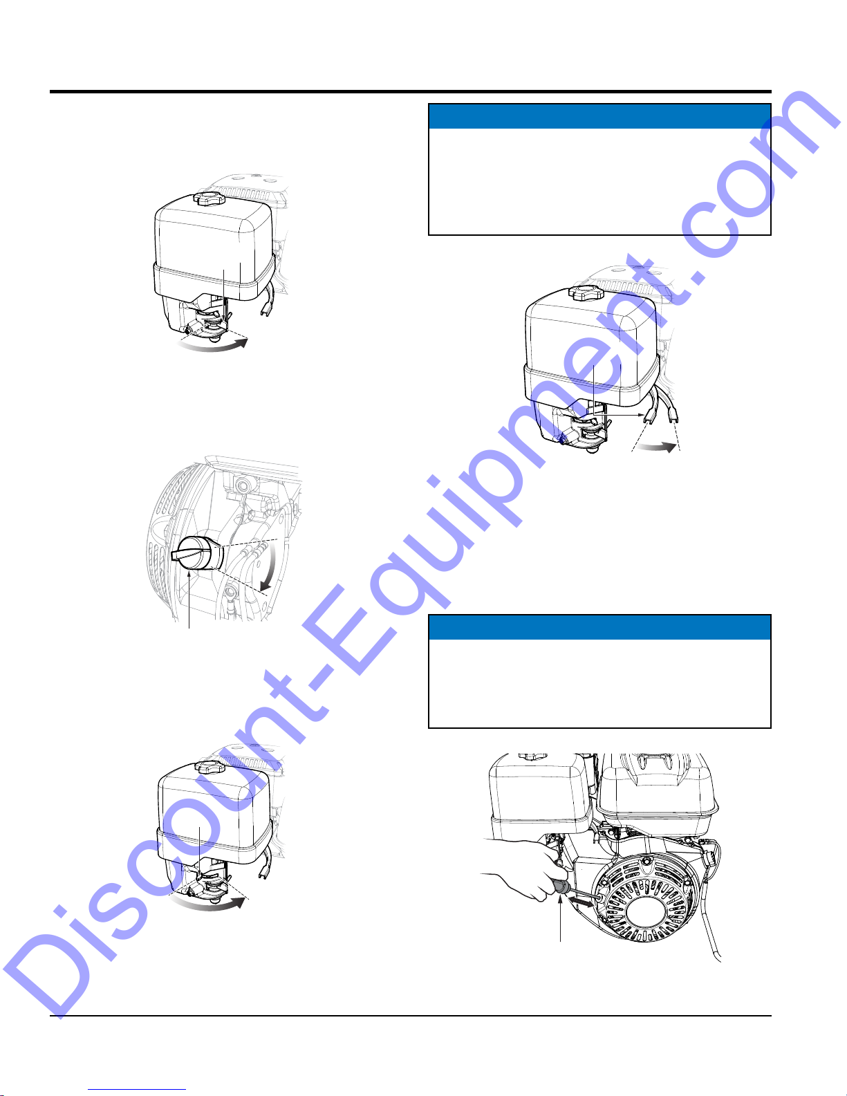
INITIAL START-UP
1. Place the fuel valve lever (Figure 12) in the ON position.
FUEL VALVE
LEVER
OFF
Figure 12. Fuel Valve Lever (ON)
2. Place the engine ON/OFF switch (Figure 13) in the
ON position.
ON
NOTICE
The CLOSED position of the choke lever enriches the
fuel mixture for starting a COLD engine. The OPEN
position provides the correct fuel mixture for normal
operation after starting, and for restarting a warm
engine.
4. Place the throttle lever (Figure 15) in the IDLE position.
THROTTLE
LEVER
RUN
Figure 15. Throttle Lever (Idle Position)
IDLE
OFF
ON
ENGINE SWITCH
Figure 13. Engine ON/OFF Switch
3. Place the choke lever (Figure 11) in the OPEN position.
CHOKE LEVER
CLOSE
OPEN
5. Grasp the starter grip (Figure 16) and slowly pull it
out. The resistance becomes the hardest at a certain
position, corresponding the compression point. Rewind
the rope a little from that point and pull out sharply.
NOTICE
DO NOT pull the starter rope all the way to the end.
DO NOT release the starter rope after pulling. Allow it
to rewind as soon as possible.
Figure 14. Choke Lever
PAGE 20 —MVC82VH/VHW PLATE COMPACTOR • OPERATION AND PARTS MANUAL — REV. #3 (12/21/17)
Figure 16. Starter Grip
OPERATION
Discount-Equipment.com
6. If the choke lever was moved to the CLOSED position,
slowly return the choke lever to the OPEN position.
7. If the engine has not started, repeat steps 1 through 5.
8. Before the compactor is put into operation, run the
engine for 3-5 minutes.
9. Check for abnormal engine noises or fuel leaks.
OPERATION
CAUTION
Make sure to follow all safety rules referenced in
the safety information section of this manual before
operating compactor. Keep work area clear of debris
and other objects that could cause damage to the
compactor or bodily injury.
1. Once the engine has started, move the engine throttle
lever quickly to the RUN position.
NOTICE
ALWAYS move the throttle lever quickly without
hesitation, because increasing the engine speed slowly
causes the clutch to slip.
3. Firmly grasp the compactor's handle bar with both
hands. The compactor will begin moving forward.
4. Slowly walk behind the compactor and be on the
lookout for any large objects or foreign matter that
might cause damage to the compactor or bodily injury.
5. Compactor traveling speed may drop on soils which
contain clay. However, there may be cases where
traveling speed drops because the compaction plate
does not leave the ground surface easily due to the
composition of the soil. To rectify this problem, do the
following:
a. Check the bottom plate to see if clay or equivalent
material has been lodged in the plate mechanism.
If so, wash with water and remove.
THROTTLE
LEVER
RUN
Figure 17. Throttle Lever (Run Position)
2. With the throttle lever in the RUN position, the engine
speed should be around 2,300 RPM therefore
engaging the centrifugal clutch.
IDLE
b. Remember the compactor does not work as
efficiently on clay or soils that have a high moisture
content level. If the soil has a high moisture level,
dry soil to appropriate moisture content level or
carry out compaction twice.
STOPPING THE ENGINE
CAUTION
NEVER stop the engine suddenly while working at
high speeds.
Normal Shutdown
1. Place the throttle lever (Figure 15) in the IDLE position,
and listen for the engine speed to decrease.
2. Place the engine ON/OFF switch (Figure 10) in the
OFF position.
3. Place the fuel valve lever (Figure 9) in the OFF position.
Emergency Shutdown
MVC82VH/VHW PLATE COMPACTOR • OPERATION AND PARTS MANUAL — REV. #3 (12/21/17) — PAGE 21
Move the throttle lever quickly to the IDLE position, and
place the engine ON/OFF switch in the OFF position.

MAINTENANCE
Discount-Equipment.com
NOTICE
Inspection and other services should always be carried
out on hard and level ground with the engine shutdown.
NOTICE
The inspection intervals listed in the maintenance tables
are for operation under normal conditions. Adjust your
inspection intervals based on the number hours plate
compactor is in use, and particular working conditions.
Table 6. Engine Maintenance Schedule
DESCRIPTION
(3)
Engine Oil
Air Cleaner
OPERATION BEFORE
Check X
Change X
Check X
Change X (1)
FIRST
MONTH OR
10 HRS.
NOTICE
Fuel piping and connections should be replaced every
2 years.
EVERY 3
MONTHS
OR 25 HRS.
EVERY 6
MONTHS
OR 50 HRS.
EVERY
YEAR OR
100 HRS.
EVERY 2
YEARS OR
200 HRS.
All Nuts and
Bolts
Spark Plugs
Cooling Fins Check X
Spark Arrester Clean X
Fuel Tank Clean X
Fuel Filter Check X
Idle Speed
Valve
Clearance
Fuel Lines Check Every 2 years (replace if necessary) (2)
(1) Service more frequently when used in DUSTY areas.
(2) These items should be serviced by your service dealer, unless you have the proper tools and are mechanically
proficient. Refer to the HONDA Shop Manual for service procedures.
(3) For commercial use, log hours of operation to determine proper maintenance intervals.
Retighten if
necessary
Check/Clean X
Replace X
Check/
Adjust
Check/
Adjust
X
X (2)
X (2)
PAGE 22 —MVC82VH/VHW PLATE COMPACTOR • OPERATION AND PARTS MANUAL — REV. #3 (12/21/17)
MAINTENANCE
Discount-Equipment.com
MACHINE INSPECTION
Perform machine inspection as listed in Table 7.
Table 7. Machine Inspection
Interval Check Solution
Machine Clean if necessary.
Fuel Tank For Leaks Repair fuel leaks.
Fuel System for Leaks Repair fuel leaks.
Engine Oil Add oil if necessary.
Vibrator Oil Add oil if necessary.
Air Cleaner Element Clean/Replace
Daily Before Starting
Every 20 Hours Engine Oil/Oil Filter
Every 100 Hours
Every 200 hours
Every 300 hours
Every 2 years Fuel Lines Replace
Guard Frame Inspect/deformations
Shock Absorber Replace if damaged.
Hydraulic pump Check/Repair Leaks
Hydraulic Pipe System
Direction Control Lever
Duct Hose
Engine Oil Change
Engine Oil Filter Wash
Vibrator Oil
Hydraulic Oil
V-Belt
Clutch
Engine Bolts
Vibrator Oil Change
Fuel Filter Change
Hydraulic Oil Change
Engine Oil Filter Change
Check/Repair leaks,
Inspect for wear
Check bolts/nuts,
Inspect for wear
Check for crack/
damage
Replace only after
first 20 hrs.
Check oil level.
Check for leaks/dirt.
Check oil level.
Check for leaks.
Inspect, replace if
damaged or worn.
Inspect, replace if not
working properly.
Replace bolts
if deformed or
elongated.
TIGHTENING TORQUE
Reference Table 8 below (Tightening Torque ), for retightening of nuts and bolts.
Table 8. Tightening Torque (kg/cm) Diameter
Material
Threads in use with this machine are all right handed.
Material and quality of material is marked on each bolt and screw.
6 mm 8 mm 10mm 12mm 14mm 16mm 18mm 20mm
4T 70 150 300 500 750 1,100 1,400 2,000
6-8T 100 250 500 800 1,300 2,000 2,700 3,800
11T 150 400 800 1,200 2,000 2,900 4,200 5,600
*
In case counterpart is of aluminum
*
100 (6mm) 300 ~ 350 (8mm) 650 ~ 700 (10mm)
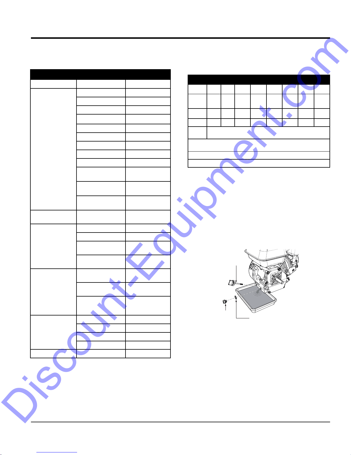
ENGINE OIL
1. Replace the engine oil in first 20 hours of operation
and every 100 hours afterwards.
2. Drain the engine oil when the oil is warm after
operation. Remove the oil filler cap then unscrew the
engine oil drain plug located at the base of the engine.
Drain the old oil into a pan (Figure 18).
OIL FILLER
DIPSTICK
DRAIN
BOLT
Figure 18. Engine Oil (Draining)
3. Replace engine oil with recommended type oil as listed
in Table 5. For engine oil capacity, see Table 2 (engine
specifications). DO NOT overfill.
SEALING
WASHER
MVC82VH/VHW PLATE COMPACTOR • OPERATION AND PARTS MANUAL — REV. #3 (12/21/17) — PAGE 23
4. Reinstall drain bolt with sealing washer and tighten
securely.
MAINTENANCE
ELEMENT
BLOW COMPRESSED
Discount-Equipment.com
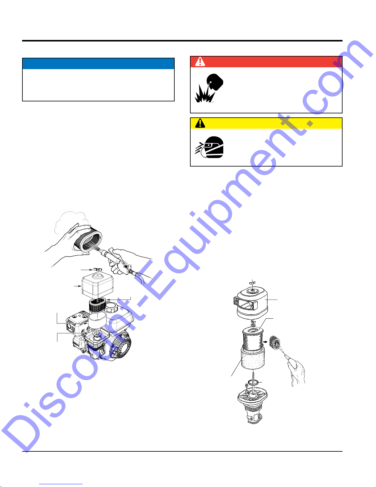
STANDARD FILTER ELEMENT
NOTICE
Operating the engine with loose or damaged air cleaner
components could allow unfiltered air into the engine
causing premature wear and failure.
The Honda GX160U1SM12 and GX160U1SMX4 engines
are equipped with a replaceable, high-density paper
air cleaner element. See (Figure 19) for air cleaner
components.
1. Remove the air cleaner cover and foam filter element.
2. Tap the paper filter element several times on a hard
surface to remove dirt, or blow compressed air not
exceeding 30 psi (207 kPa, 2.1 kgf/cm2) through the
filter element from the inside out. NEVER brush off
dirt. Brushing will force dirt into the fibers. Replace the
paper filter element if it is excessively dirty.
BLOW COMPRESSED
AIR FROM THE
INSIDE OUT
WING NUT
AIR CLEANER
COVER
FOAM FILTER
ELEMENT
PAPER FILTER
ELEMENT
CYCLONE FILTER ELEMENT TYPE 1
DANGER
DO NOT use gasoline or low flash point
solvents for cleaning the air cleaner. The
possibility exists of fire or explosion which
can cause damage to the equipment and
severe bodily harm or even DEATH!
CAUTION
Wear protective equipment such as
approved safety glasses or face shields
and dust masks or respirators when
cleaning air filters with compressed air.
The Honda GX160UT2QMXC and GX160UT2SMXC
engines are equipped with a replaceable, high-density
paper air cleaner element. See (Figure 20) for air cleaner
components.
1. Remove the air cleaner cover and foam filter element.
2. Tap the paper filter element several times on a hard
surface to remove dirt, or blow compressed air not
exceeding 30 psi (207 kPa, 2.1 kgf/cm2) through the
filter element from the inside out. NEVER brush off
dirt. Brushing will force dirt into the fibers. Replace the
paper filter element if it is excessively dirty.
WING NUT
AIR CLEANER
COVER
PAPER
FILTER
ELEMENT
GASKET
Figure 19. Engine Air Filter (Standard)
PAGE 24 —MVC82VH/VHW PLATE COMPACTOR • OPERATION AND PARTS MANUAL — REV. #3 (12/21/17)
AIR FROM THE
INSIDE OUT
FOAM
FILTER
Figure 20. Engine Air Filter
GASKET
P
AIR CLEANER
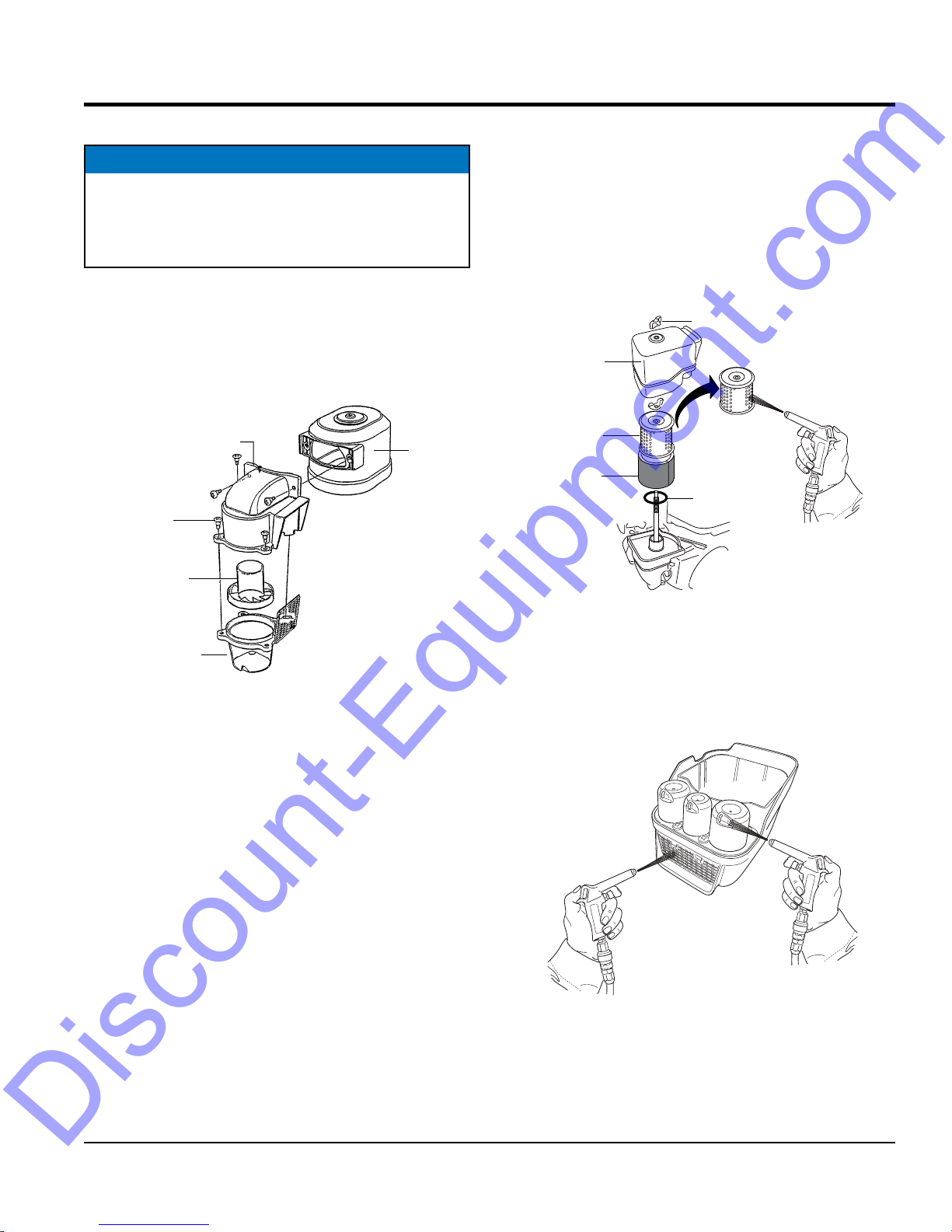
MAINTENANCE
Discount-Equipment.com
DUST POT
NOTICE
When reinstalling cyclone housing, be sure that the air
intake tab fits properly into the groove in the pre-cleaner
cap. Also make sure air guide is properly aligned before
inserting into pre-cleaner cap.
Always clean the dust pot. A clogged dust pot reduces
cyclone effect with cleaner element wearing easily.
1. Remove the four pan head screws that secure the dust
pot to pre air cleaner case cover (Figure 21).
PRE AIR CLEANER
CASE COVER
AN HD. MOUNTING
SCREWS (4)
PRE AIR
CLEANER
GUIDE
COVER
CYCLONE FILTER ELEMENT TYPE 2
The Honda GX160UT2SCM engines are equipped with a
replaceable, high-density paper air cleaner element. See
(Figure 22) for air cleaner components.
1. Follow steps 1 through 3 as outlined in the "Dual Filter
Element" section.
WING NUT
AIR CLEANER
COVER
PAPER FILTER
ELEMENT
FOAM FILTER
ELEMENT
GASKET
BLOW COMPRESSED
AIR FROM THE
INSIDE OUT
PRE AIR
CLEANER
CASE
(DUST POT)
Figure 21. Removing Dust Pot
Figure 22. Engine Air Filter (Cyclone Type 2)
2. Blow compressed air through the air cleaner cover as
shown in Figure 23. Clean inside of air filter cover with
warm, soapy water or nonflammable solvent. Rinse
and dry thoroughly.
BLOW COMPRESSED AIR
Figure 23. Engine Air Filter Cover
MVC82VH/VHW PLATE COMPACTOR • OPERATION AND PARTS MANUAL — REV. #3 (12/21/17) — PAGE 25
 Loading...