

MQ Multiquip MP1H, MP115E, MP120E Parts Manual

OPERATION AND PARTS MANUAL
MP1 SERIES
MODELS
MP1H (4.8 HP GASOLINE)
MP115E (1.5 HP ELECTRIC)
MP120E (2.0 HP ELECTRIC)
MASONRY SAWS
Revision #2 (10/12/17)
To find the latest revision of this
publication, visit our website at:
www.multiquip.com
THIS MANUAL MUST ACCOMPANY THE EQUIPMENT AT ALL TIMES.
P/N 38261
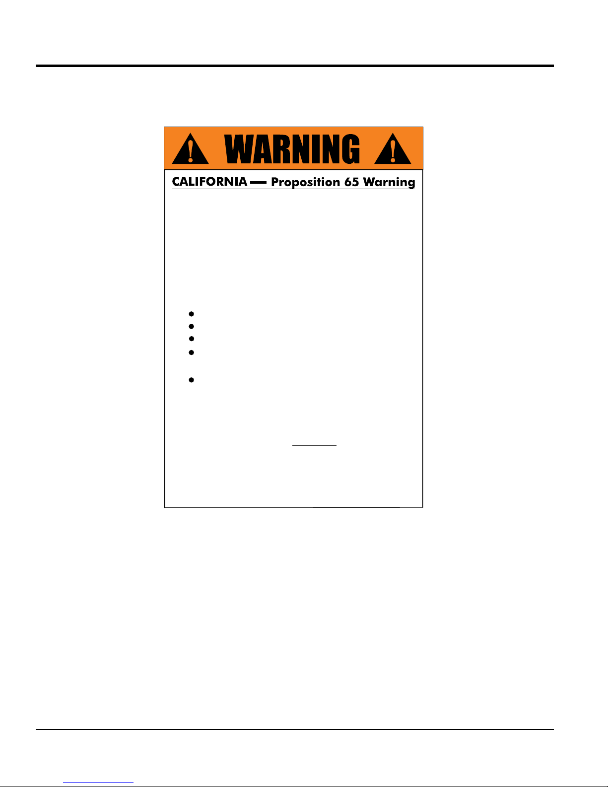
PROPOSITION 65 WARNING
Engine exhaust and some of
its constituents, and some dust created
by power sanding, sawing, grinding,
drilling and other construction activities
contains chemicals known to the State
of California to cause cancer, birth
defects and other reproductive harm.
Some examples of these chemicals are:
Lead from lead-based paints.
Crystalline silica from bricks.
Cement and other masonry products.
Arsenic and chromium from chemically
treated lumber.
Di-lsononyl Phthalate (DINP)
Your risk from these exposures varies,
depending on how often you do this type
of work. To reduce your exposure to
these chemicals: ALWAYS work in a
well ventilated area, and work with
approved safety equipment, such as
dust masks that are specially designed
to filter out microscopic particles.
PAGE 2 — MP1 SERIES MASONRY SAW • OPERATION AND PARTS MANUAL — REV. #2 (10/12/17)

SILICOSIS/RESPIRATORY WARNINGS
WARNING
SILICOSIS WARNING RESPIRATORY HAZARDS
Grinding/cutting/drilling of masonry, concrete, metal and
other materials with silica in their composition may give
off dust or mists containing crystalline silica. Silica is a
basic component of sand, quartz, brick clay, granite and
numerous other minerals and rocks. Repeated and/or
substantial inhalation of airborne crystalline silica can
cause serious or fatal respiratory diseases, including
silicosis.In addition, California and some other
authorities have listed respirable crystalline silica as a
substance known to cause cancer. When cutting such
materials, always follow the respiratory precautions
mentioned above.
WARNING
Grinding/cutting/drilling of masonry, concrete, metal and
other materials can generate dust, mists and fumes
containing chemicals known to cause serious or fatal
injury or illness, such as respiratory disease, cancer,
birth defects or other reproductive harm. If you are
unfamiliar with the risks associated with the particular
process and/or material being cut or the composition of
the tool being used, review the material safety data
sheet and/or consult your employer, the material
manufacturer/supplier, governmental agencies such as
OSHA and NIOSH and other sources on hazardous
materials. California and some other authorities, for
instance, have published lists of substances known to
cause cancer, reproductive toxicity,or other harmful
effects.
MP1 SERIES MASONRY SAW • OPERATION AND PARTS MANUAL — REV. #2 (10/12/17) — PAGE 3
Control dust, mist and fumes at the source where
possible. In this regard use good work practices and
follow the recommendations of the manufacturers or
suppliers, OSHA/NIOSH, and occupational and trade
associations.Water should be used for dust
suppression when wet cutting is feasible. When the
hazards from inhalation of dust, mists and fumes cannot
be eliminated, the operator and any bystanders should
always wear a respirator approved by NIOSH/MSHA for
the materials being used.

TABLE OF CONTENTS
MP1 Masonry Saw
Proposition 65 Warning ........................................... 2
Silicosis/Respiratory Warnings ................................ 3
Table Of Contents .................................................... 4
Parts Ordering Procedures ...................................... 5
Safety Information ................................................ 6-9
Specifications ........................................................ 10
Dimensions ............................................................ 11
General Information ............................................... 12
Saw Components ............................................. 14-15
Electric Motor Components ................................... 16
Engine Components .............................................. 17
Set-Up .............................................................. 18-23
Operation .......................................................... 24-27
Maintenance ..................................................... 28-31
Wiring Diagram (Electric Motor) ............................ 32
Troubleshooting (Blade) ......................................... 33
Troubleshooting (Electric Motor) ............................ 34
Troubleshooting (Engine) ....................................... 35
Explanation Of Codes In Remarks Column ........... 36
Suggested Spare Parts ......................................... 37
HONDA GX160K1QXC9 Drawings
Air Cleaner Assembly ....................................... 54-55
Camshaft Assembly .......................................... 56-57
Carburetor Assembly ........................................ 58-59
Control Assembly ............................................. 60-61
Crankcase Cover Assembly ............................. 62-63
Crankshaft Assembly ........................................ 64-65
Cylinder Barrel Assembly ................................. 66-67
Cylinder Head Assembly .................................. 68-69
Fan Cover Assembly......................................... 70-71
Flywheel Assembly ........................................... 72-73
Fuel Tank Assembly .......................................... 74-75
Ignition Coil Assembly ...................................... 76-77
Muffler Assembly .............................................. 78-79
Piston And Rings Assembly ............................. 80-81
Recoil Starter Assembly ................................... 82-83
Gasket Kit Assembly ........................................ 84-85
Labels Assembly .............................................. 86-87
Terms And Conditions ........................................... 88
Component Drawings
Name Plate And Decals ................................... 38-39
Tray Assembly .................................................. 40-41
Cart Assembly .................................................. 42-43
Motor Plate And Shaft Assembly ...................... 44-45
Engine Honda 4.8 HP Assembly ...................... 46-47
Electric Motor Assembly ................................... 48-49
Water Pump Assembly (Gasoline Only) ...........50-51
Support Stand Assembly (Option) .................... 52-53
NOTICE
Specifications are subject to change without notice.
PAGE 4 — MP1 SERIES MASONRY SAW • OPERATION AND PARTS MANUAL — REV. #2 (10/12/17)
PARTS ORDERING PROCEDURES
www.multiquip.com
Ordering parts has never been easier!
If you have an MQ Account, to obtain a Username
parts@multiquip.
To obtain an MQ Account, contact your
Effective:
, 2006
Choose from three easy options:
January 1
st
Best Deal!
Order via Internet (Dealers Only):
Order parts on-line using Multiquip’s SmartEquip website!
View Parts Diagrams
Order Parts
Print Specifi cation Information
Goto www.multiquip.com and click on
Order Parts
to log in and save!
Order via Fax (Dealers Only):
All customers are welcome to order parts via Fax.
Domestic (US) Customers dial:
1-800-6-PARTS-7 (800-672-7877)
Order via Phone:
Non-Dealer Customers:
Contact your local Multiquip Dealer for
parts or call 800-427-1244 for help in
locating a dealer near you.
and Password, E-mail us at:
com.
District Sales Manager for more information.
Use the internet and qualify for a 5% Discount
on Standard orders for all orders which include
complete part numbers.*
Fax your order in and qualify for a 2% Discount
on Standard orders for all orders which include
complete part numbers.*
Domestic (US) Dealers Call:
1-800-427-1244
International Customers should contact
their local Multiquip Representatives for
Parts Ordering information.
Note: Discounts Are Subject To Change
Note: Discounts Are Subject To Change
MP1 SERIES MASONRY SAW • OPERATION AND PARTS MANUAL — REV. #2 (10/12/17) — PAGE 5
When ordering parts, please supply:
Dealer Account Number
Dealer Name and Address
Shipping Address (if different than billing address)
Return Fax Number
Applicable Model Number
Quantity, Part Number and Description of Each Part
NOTICE
All orders are treated as Standard Orders and will
ship the same day if received prior to 3PM PST.
WE ACCEPT ALL MAJOR CREDIT CARDS!
Specify Preferred Method of Shipment:
UPS/Fed Ex DHL
Priority One Tr u ck
Ground
Next Day
Second/Third Day
SAFETY INFORMATION
Do not operate or service the equipment before reading
the entire manual. Safety precautions should be followed
at all times when operating this equipment.
Failure to read and understand the safety
messages and operating instructions could
result in injury to yourself and others.
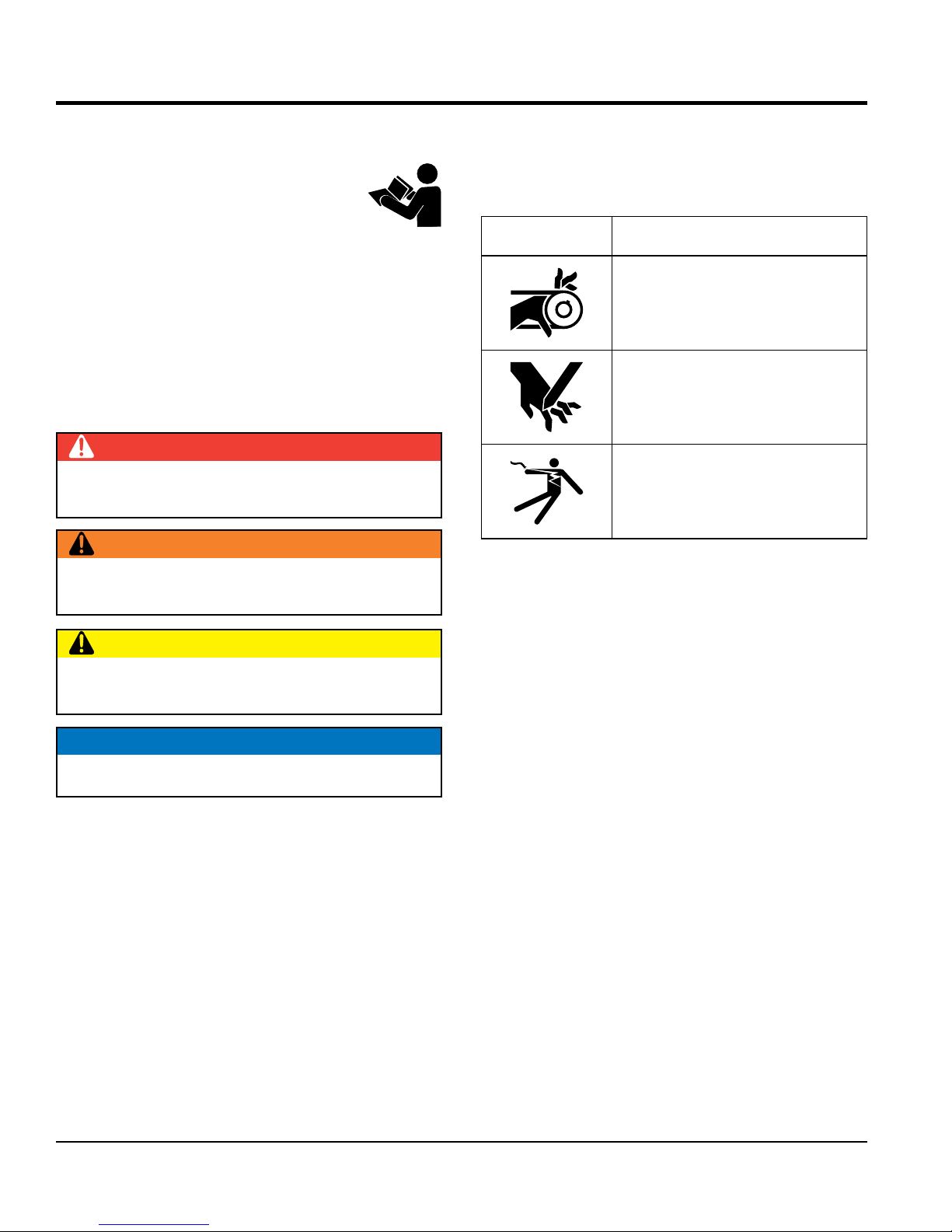
SAFETY MESSAGES
The four safety messages shown below will inform you
about potential hazards that could injure you or others. The
safety messages specifi cally address the level of exposure
to the operator and are preceded by one of four words:
DANGER, WARNING, CAUTION
SAFETY SYMBOLS
Potential hazards associated with the operation of this
equipment will be referenced with hazard symbols which
may appear throughout this manual in conjunction with
safety messages.
DANGER
Indicates a hazardous situation which, if not avoided,
WILL result in DEATH or SERIOUS INJURY.
WARNING
Indicates a hazardous situation which, if not avoided,
COULD result in DEATH or SERIOUS INJURY.
CAUTION
Indicates a hazardous situation which, if not avoided,
COULD result in MINOR or MODERATE INJURY.
or NOTICE.
Symbol Safety Hazard
Rotating parts hazards
Cutting and crushing hazards
Electric shock hazards
NOTICE
Addresses practices not related to personal injury.
PAGE 6 — MP1 SERIES MASONRY SAW • OPERATION AND PARTS MANUAL — REV. #2 (10/12/17)
SAFETY INFORMATION
GENERAL SAFETY
No one other than the operator is to be in the working
check the equipment for loosened threads or
use the equipment for any purpose other than
This equipment should only be operated by trained and
Whenever necessary, replace nameplate, operation and
Manufacturer does not assume responsibility for any
accident due to equipment modifi cations. Unauthorized
use accessories or attachments that are not
recommended by Multiquip for this equipment. Damage
keep
Also, know the phone numbers
fi re department.
This information will be invaluable in the case of an
WARNING
Adherence to the OSHA 2017 Ruling governing
Occupational Exposure to Respirable Crystalline Silica,
requires that all sawing operations MUST BE conducted
with an integrated water delivery system that feeds water
to the blade.
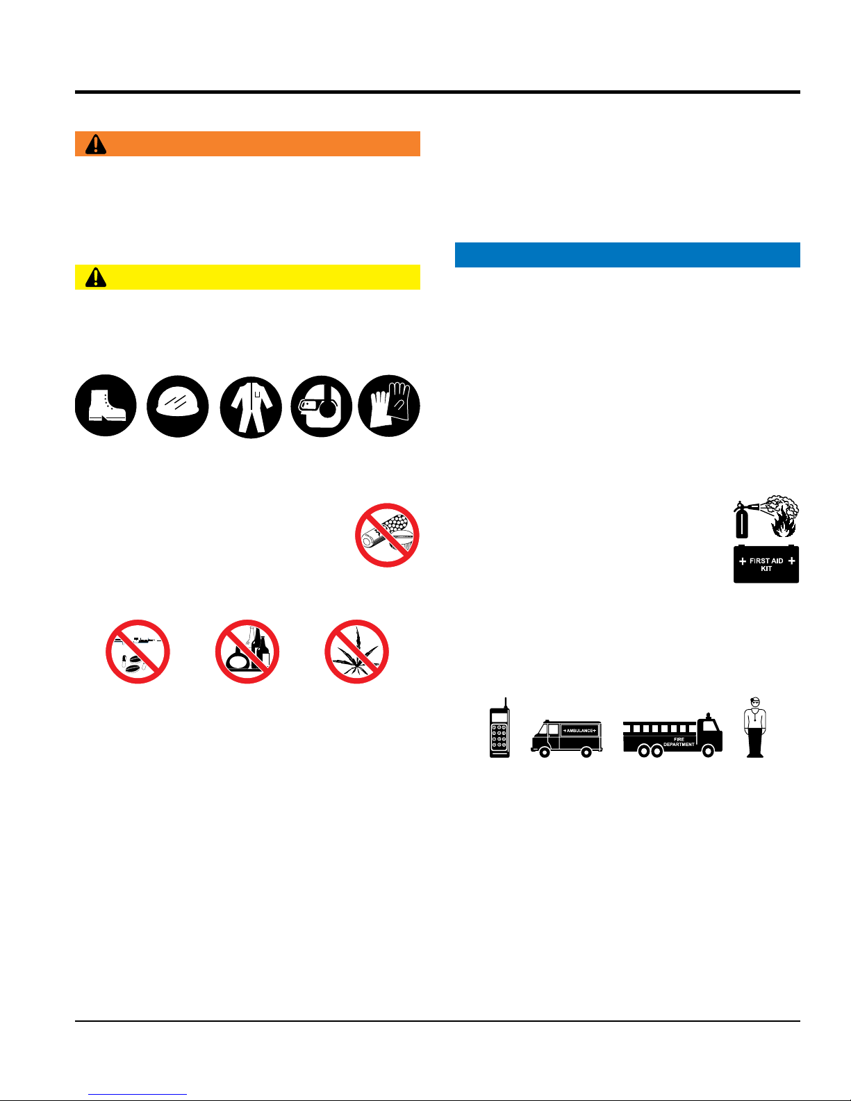
CAUTION
NEVER operate this equipment without proper protective
clothing, shatterproof glasses, respiratory protection,
hearing protection, steel-toed boots and other protective
devices required by the job or city and state regulations.
Avoid wearing jewelry or loose fi tting clothes that may
snag on the controls or moving parts as this can cause
serious injury.
NEVER operate this equipment when not
feeling well due to fatigue, illness or when
under medication.
NEVER operate this equipment under the
infl uence of drugs or alcohol.
area when the equipment is in operation.
ALWAYS
bolts before starting.
DO NOT
its intended purposes or applications.
NOTICE
qualifi ed personnel 18 years of age and older.
safety decals when they become diffi cult read.
equipment modifi cation will void all warranties.
NEVER
to the equipment and/or injury to user may result.
ALWAYS know the location of the nearest
fi re extinguisher.
ALWAYS know the location of the nearest
fi rst aid kit.
ALWAYS know the location of the nearest phone or
a phone on the job site.
of the nearest ambulance, doctor and
emergency.
ALWAYS clear the work area of any debris, tools, etc.
that would constitute a hazard while the equipment is
in operation.
MP1 SERIES MASONRY SAW • OPERATION AND PARTS MANUAL — REV. #2 (10/12/17) — PAGE 7
SAFETY INFORMATION
SAW SAFETY
BLADE SAFETY
Verify the motor start switch is set to the OFF position
Use proper blades and follow blade manufacturer’s
recommendations. Match the blade RPM (blade shaft
RPM) to the recommended blade surface feet per minute
Ensure the blade-mounting bolt is tightened
examine blade flanges for damage and
Ensure the blade is marked with an operating speed
Only cut the material that is specifi ed for the diamond
blade. Read the specifi cation of the diamond blade to
ensure the proper tool has been matched to the material
Ensure that water is used during sawing operations and
that a suffi cient fl ow of water is applied to both sides of
drop the diamond blade on ground or surface.
Ensure that the blade is mounted for proper operating
Adhere to the blade manufacturer’s recommendations
CAUTION
DANGER
NEVER operate the equipment in an explosive atmosphere
or near combustible materials. An explosion or fi re could
result causing severe bodily harm or even death.
WARNING
Accidental starting can cause severe injury
or death. ALWAYS place the ON/OFF
switch in the OFF position.
Keep hands away from moving parts at all
times.
NEVER disconnect any emergency
or safety devices. These devices are
intended for operator safety. Disconnection of these
devices can cause severe injury, bodily harm or even
death. Disconnection of any of these devices will void
all warranties.
CAUTION
ALWAYS ensure saw is securely placed on appropriate
blocks or jackstands when maintenance requires
elevation of the saw.
If the machine malfunctions, stop the saw immediately
and secure it. Fix the problem as soon as possible.
NOTICE
NEVER operate the saw without blade
guards and covers in place. Exposure of
the diamond blade must not exceed 180
degrees.
before installing a blade.
ALWAYS inspect blade before each
use. The blade should exhibit no cracks,
dings, or fl aws in the steel centered core
and/or rim. Center (arbor) hole must be
undamaged and true.
NOTICE
(SFPM).
adequately
ALWAYS
excessive wear.
greater than the spindle speed of the saw.
ALWAYS keep the machine in proper running condition.
Fix damage to machine and replace any broken parts
immediately.
Make sure there is no buildup of grease, oil or debris
on the machine.
ALWAYS store equipment properly when it is not being
used. Equipment should be stored in a clean, dry location
out of the reach of children and unauthorized personnel.
WARNING
Rotating blade can cut and crush. ALWAYS
keep hands and feet clear while operating
the saw.
PAGE 8 — MP1 SERIES MASONRY SAW • OPERATION AND PARTS MANUAL — REV. #2 (10/12/17)
being cut.
the blade.
DO NOT
direction.
on handling, storage and safe usage of blades.
SAFETY INFORMATION
ELECTRIC MOTOR SAFETY
Power Cord/Cable Safety
LIFTING SAFETY
allow any person or animal to stand underneath
Some saws are very heavy and awkward to move around.
tie down equipment during transport by
Ensure that the diamond blade does not come into contact
transport the saw to or from the job site with the
use food or plastic containers to dispose of
pour waste, oil or fuel directly onto the ground,
NOTICE
Operate electric motor only at the specifi ed voltage
indicated on the nameplate.
DO NOT spray water onto electric motor.
ALWAYS disconnect AC power plug from power source
before moving saw, changing blade, or performing
maintenance.
ALWAYS make sure the ON/OFF switch
on the electric motor is in the OFF position
when not in use and before inserting the
saw’s power plug into an AC receptacle.
DANGER
NEVER let power cords or cables lay in water.
NEVER use damaged or worn cables or cords when
connecting equipment to generator. Inspect for cuts in
the insulation.
CAUTION
NEVER
the equipment while lifting.
Use proper heavy lifting procedures.
DO NOT lift machine to unnecessary heights.
NEVER lift the equipment while the motor is running.
TRANSPORTING SAFETY
NOTICE
ALWAYS shutdown motor before transporting.
ALWAYS
securing the equipment with rope.
with the ground or surface during transportation.
NEVER
blade mounted.
NEVER grab or touch a live power
cord or cable with wet hands. The
possibility exists of electrical shock,
electrocution or death.
Make sure power cables are securely
connected. Incorrect connections may
cause electrical shock and damage to the
saw.
CAUTION
Ensure that cables and cords will not be tripped over or
trapped underneath the saw.
Never use the cable to pull out the plug from the power
source.
NOTICE
ALWAYS make certain that proper power or extension
cord has been selected for the job.
Protect the cable from heat, oil, and sharp edges.
ENVIRONMENTAL SAFETY
NOTICE
Dispose of hazardous waste properly.
Examples of potentially hazardous waste
are used motor oil, fuel and fuel fi lters.
DO NOT
hazardous waste.
DO NOT
down a drain or into any water source.
MP1 SERIES MASONRY SAW • OPERATION AND PARTS MANUAL — REV. #2 (10/12/17) — PAGE 9

Table 1. Saw Specifications
SPECIFICATIONS
Dimensions
Approximate Weight
Electric
Motor Speed
Blade Shaft Speed
Water Pump
Engine (Gasoline)
Type
Blade Shaft Speed
Water Pump
General
Blade Capacity
Cutting Depth
Table 2. MP1 Electric Motor/Engine Specifications
Saw Model MP1H MP115E MP120E
43.75" x 33" x 27" (111.125 cm x 83.82 cm x 68.58 cm)
165 lbs. (75 Kg.)
3450 RPM (See Table 2)
2,729 RPM
115V/60Hz Oil-filled, 300 GPM
4.8 HP 4 cycle, Single Cylinder, Air Cooled, Honda
(See Table 2)
2,958 RPM
Mechanical centrifugal, 138 GPM
14 in. blade maximum
5 in. with 14 in. blade
Engine/Motor Honda GX160K1QXC9
Type 4-Stroke OHV Single Cylinder
Bore xStroke 2.7 x 1.8in. (68 x 45mm)
Displacement 9.9 cu. in. (163 cc)
Max Engine Output 4.8 HP @ 3600 rpm
Fuel Tank Cap. 0.95 US Gal. (3.6 liters)
Fuel Unleaded Gasoline
Lube Oil Cap. 0.63 US Qt. (0.60 liters)
Speed Control
Method
Starting Method Recoil Start
Dimension
Dry Net Weight 33.1 lbs. (15.0 kg)
Centrifugal Fly-Weight type
12.0 x 14.3 x 13.2 in
(304 x 362 x 335mm)
1.5 HP
Heavy Duty Electric
115/230V
Single Phase
60Hz
Dual Voltage
Amps F.L
17.2/8.6
2.0 HP
Heavy Duty Electric
115/230V
Single Phase
60Hz
Dual Voltage
Amps F.L
16.8/8.4
PAGE 10 — MP1 SERIES MASONRY SAW • OPERATION AND PARTS MANUAL — REV. #2 (10/12/17)
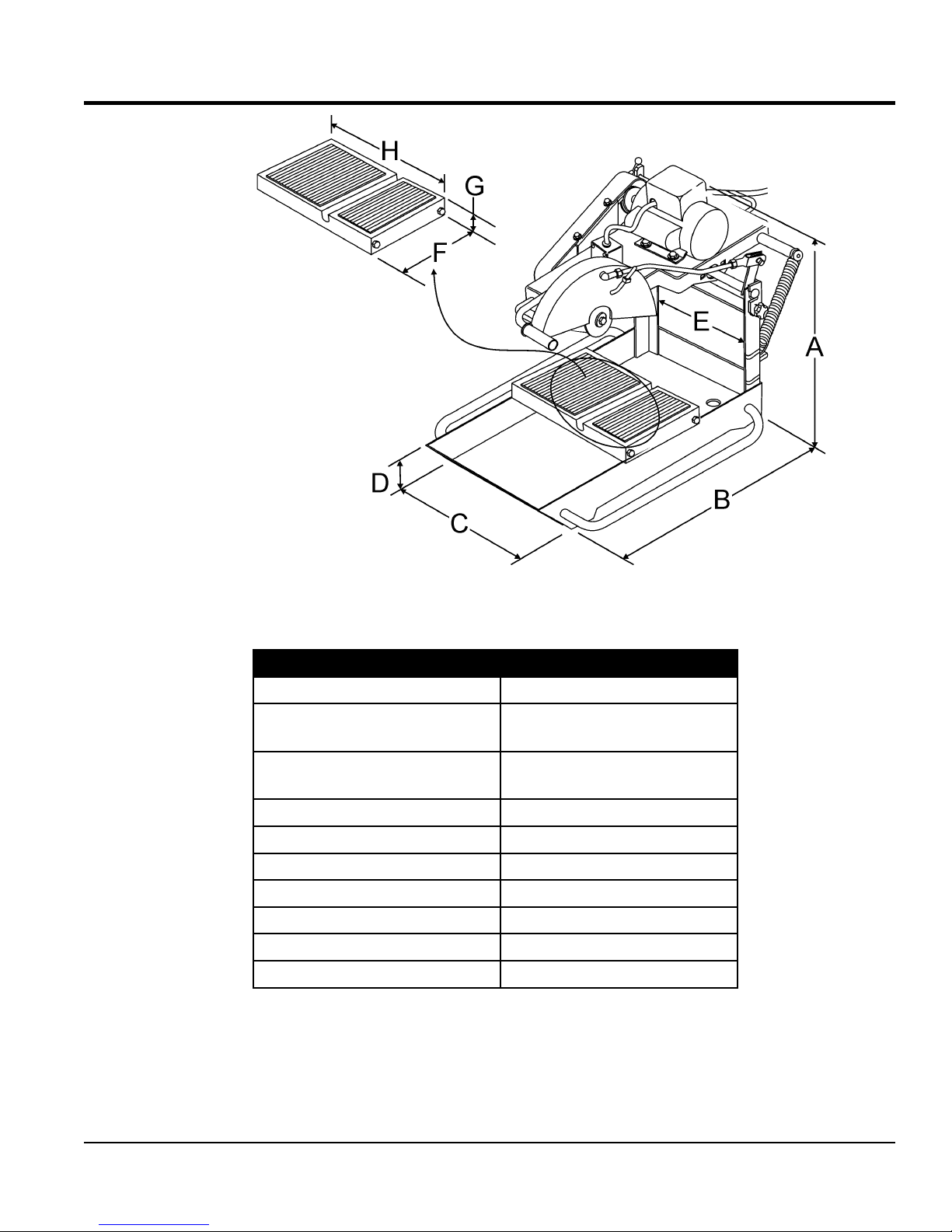
DIMENSIONS
Figure 1. Dimensions
Table 3. Dimension
Reference Letter Dimensions
A
(electric motor)
A
(gasoline engine)
29.0 in. (74 cm)
29.0 in. (74 cm)
B 42.0 in. (106 cm)
C 27.0 in. (58.6 cm)
D 5.5 in. (13.97 cm)
E 14.5 in. (36.8 cm)
F 11.5 in. (29.2 cm)
G 2.5 in. (6.35 meters)
H 19.0 in. (48.2 meters)
MP1 SERIES MASONRY SAW • OPERATION AND PARTS MANUAL — REV. #2 (10/12/17) — PAGE 11

GENERAL INFORMATION
MP1 MASONRY SAW
The MP1 masonry saw is designed for vigorous wet-cutting
masonry applications. The heavy-duty aluminum conveyor
cart and ball bearing roller wheels ensure material stability
and smooth travel. In addition a reinforced jig-welded
steel frame provides rigidity for cutting accuracy and long
service life.
This saw is available with either an electric motor or
a gasoline engine. The heavy duty electric motors are
available in either 1.5 HP or 2.0 HP with overload protection.
Each motor can operate at either 115 VAC or 230 VAC.
The electric motor input voltage is selectable by means of
a toggle switch. Always make sure that the input voltage
being supplied to the motor matches the position of the
voltage selector toggle switch located on top of the motor.
If desired, the MP1 saw can be configured with a 4.8 HP
Honda GX160 gasoline engine.
All MP1 models include a high flow water pump, cutting
jig, water hoses and associated plumbing to enable the
operator to begin wet cutting.
WET CUTTING APPLICATIONS
For operator safety, ALL sawing must be conducted with
the water delivery system that is provided with the masonry
saw. Ensure that a free flow of clean water is properly routed
from the pump through the plumbing system so that the
blade receives an ample amount of water. This action is
required to safeguard against the operational hazards of
silica exposure.
WARNING
BLADE APPLICATIONS
This saw has been designed to incorporate the use
of diamond blades as the cutting tool. The optimum
performance of this saw is best evidenced by using 14-inch
(356 mm) diamond blades that match the material being
cut. Ask your dealer, or call MULTIQUIP about your specific
cutting application.
FEATURES
1.5 or 2.0 HP, 115/230 VAC , 60 Hz heavy duty electric
motors with overload protection.
4.8 HP Honda GX160 gasoline engine.
14-inch blade capacity provides 5-inch depth of cut.
Rugged aluminum conveyor cart for optimum stability.
Open back design permits capability of cutting large
materials.
Ergonomically designed cutting head provides operator
relief in high tempo operations.
Mounted carrying handles for easy transportation.
Rubber-matted cutting table helps hold the material
being cut in place while resisting vibrations for smoother
cuts with less chipping.
Cutting table marked in inches and centimeters (ruler)
for precision cuts.
Stay-level blade guard for operator safety.
Rigid steel frame minimizes vibrations and assures
accurate cutting.
Adherence to the OSHA 2017 Ruling governing
Occupational Exposure to Respirable Crystalline
Silica, requires that all sawing operations MUST BE
conducted with an integrated water delivery system
that feeds water to the blade.
PAGE 12 — MP1 SERIES MASONRY SAW • OPERATION AND PARTS MANUAL — REV. #2 (10/12/17)
Mechanical Water Pump Kit (Gasoline Model Only)
Electric Submersible Water Pump Kit (Electric Models
Only).

NOTES
MP1 SERIES MASONRY SAW • OPERATION AND PARTS MANUAL — REV. #2 (10/12/17) — PAGE 13
SAW COMPONENTS
PAGE 14 — MP1 SERIES MASONRY SAW • OPERATION AND PARTS MANUAL — REV. #2 (10/12/17)
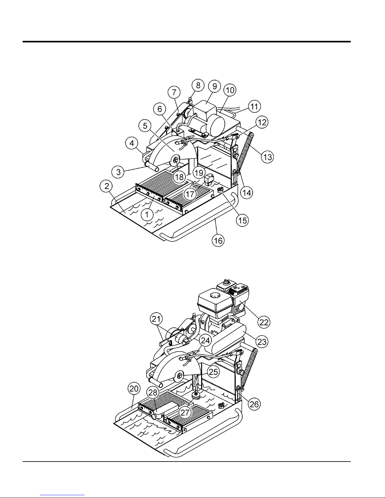
Figure 2. Saw Components

SAW COMPONENTS
Figure 2 shows the location of the basic components of
the MP1 Saw. Listed below is a brief explanation of each
component.
1. Ruler Backstop — When cutting, place material against
backstop. Use measurement rail (ruler) to determine
where material is to be cut.
2. Water Tray — When wet cutting is required, fill with clean
fresh water. Make sure submersible is totally immersed
in water.
3. Cutting Head Handle — Grab hold of this handle to
move the cutting blade head either up or down. To move
the cutting head, release the mounting plate release/
lock lever.
4. Carrying Handle (Head) — Grip this handle (front) to
lift the mounting plate.
5. Blade Guard — Protects the user from the cutting blade.
NEVER operate the saw with the blade guard removed.
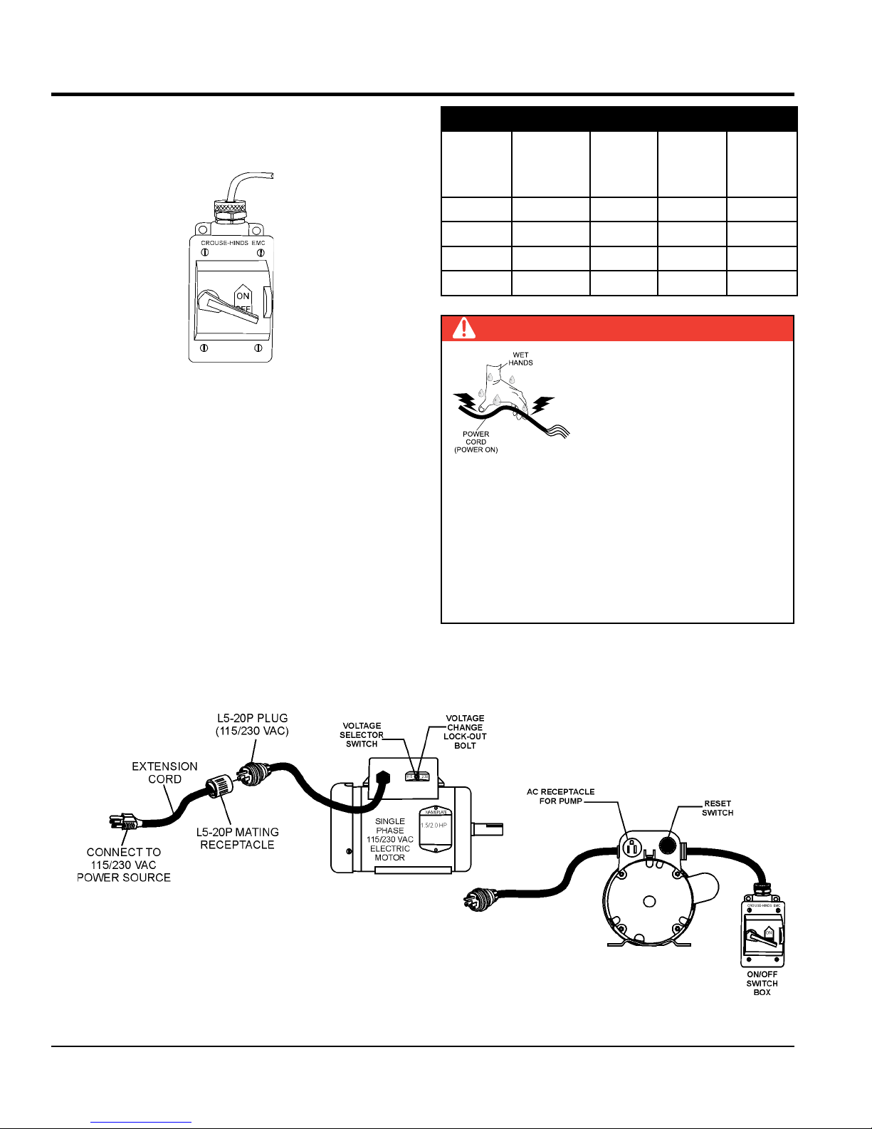
6. Power ON/OFF Box — This box is used on electric
models saws only. To turn on the saw place in the ON
position. Place in the OFF position to shut-down the saw.
14. Mounting Plate Lock/Release Knobs — Turn knob (2)
clockwise to release the mounting plate. Turn counterclockwise to tighten.
15. Stopper — Place stopper in tray when filling with water.
16. Carrying Handle (Tray) — Grip this handle (right-side)
to trasport the saw.
17. Electric Water Pump — For best results place the pump
between the splash shield and the rear of the water tray.
This is for electric models only. Plug water pump power
cord into AC receptacle on electric motor conduit box.
NEVER run pump dry. Pump must be immersed in water.
18. Spindle Bolt/Outside Blade Flange — When mounting
of the cutting blade is required, remove the spindle bolt
and outside blade flange. Align cutting blade with inside
flange arbor and reassemble spindle and outside blade
flange.
19. Splash Guard — Keeps water and debris from leaving
the water tray.
20. Carrying Handle (Tray) — Grip this handle (left-side)
to trasport the saw.
7. V-belt Cover — Remove this cover to access the drive
V-belt. NEVER operate the saw with the V-belt cover
removed.
8. Mounting Plate Release/Lock Lever — Push this lever
backwards to release the mounting plate. This will allow
the cutting head to move either up or down. Push the lever
forward to lock the mounting plate in place.
9. Electric Motor/Conduit Box — This unit uses 2 different
types of electric motors and voltages (see Table 2).
Always make sure the voltage selector switch has been
set to the correct position for the voltage being supplied
to the motor. Plug the water pump (electric models only)
power cord into the AC receptacle located on the conduit
box.
10. Mounting Plate — Supports the electric motor/gasoline
engine. Plate has slotted holes for horizontal (right-side)
and vertical (left-side) adjustment of cutting head.
11. Carrying Handle (Head) — Grip this handle (rear) to lift
the mounting plate.
12. Tie Rod — The tie rod length has been set at the factory
for best blade guard position for the majority of the cutting
that will be done.
13. Spring Tensioner — Allows for an easy up and down
movement of the mounting plate.
21. Mechanical Water Pump — This pump is used on
gasoline models only. Saw is shipped from the factor
for wet cutting applications (pump handle down). Place
pump handle upwards to disengage pump. NEVER run
pump dry.
22. Engine — The gasoline model saws uses a 4.8 HP
Honda GX160, 4-stroke, OHV, single cylinder, air cooled
gasoline engine.
23. V-belt Cover (Gasoline Only) — Remove this cover to
access the engine shaft-side V-belt. NEVER operate the
saw with the V-belt cover removed.
24. Water Lines — Replace the clear vinyl tubing water lines
when they become brittle, worn or clogged. Water kits are
available through your dealer.
25. Priming Bulb — Squeeze this bulb to prime the
mechanical water pump (gasoline models only).
26. Blade Wrench — Use this tool to mount and remove
cutting blade.
27. Strainer — For best results place the strainer between
the splash shield and the rear of the water tray. This is
for gasoline models only. NEVER run pump dry. Strainer
must be immersed in water.
28. Miter Box — For angled cuts, place the lip of the miter
box on the measurement rail with the threaded thumb
knob facing you and tighten.
MP1 SERIES MASONRY SAW • OPERATION AND PARTS MANUAL — REV. #2 (10/12/17) — PAGE 15
ELECTRIC MOTOR COMPONENTS
Figure 3. Electric Motor Components
PAGE 16 — MP1 SERIES MASONRY SAW • OPERATION AND PARTS MANUAL — REV. #2 (10/12/17)
ENGINE COMPONENTS
10
9
8
7
6
5
4
Figure 4. Engine Components
1
2
3
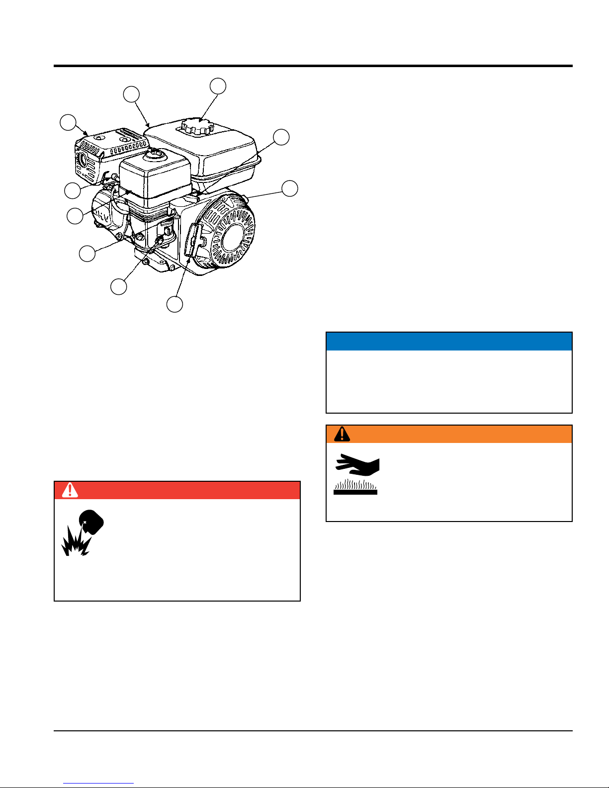
INITIAL SERVICING
The engine (Figure 4) must be checked for proper
lubrication and filled with fuel prior to operation. Refer to the
engine manufacturer’s manual for instructions and details
of operation and servicing.
1. Fuel Filler Cap — Remove this cap to add unleaded
gasoline to the fuel tank. Make sure cap is tightened
securely. DO NOT over fill.
DANGER
Adding fuel to the tank should be done
only when the engine is stopped and has
had an opportunity to cool down. In the
event of a fuel spill, DO NOT attempt to
start the engine until the fuel residue has
been completely wiped up, and the area surrounding
the engine is dry.
2. Throttle Lever — Used to adjust engine RPM speed
(lever advanced forward SLOW, lever back toward
operator FAST).
3. Engine ON/OFF Switch — ON position permits engine
starting, OFF position stops engine operations.
4. Recoil Starter (pull rope) — Manual-starting method.
Pull the starter grip until resistance is felt, then pull
briskly and smoothly.
5. Fuel Valve Lever — OPEN to let fuel flow, CLOSE to
stop the flow of fuel.
6. Choke Lever — Used in the starting of a cold engine,
or in cold weather conditions. The choke enriches the
fuel mixture.
7. Air Cleaner — Prevents dirt and other debris from
entering the fuel system. Remove wing-nut on top of
air filter cannister to gain access to filter element.
NOTICE
Operating the engine without an air filter, with a
damaged air filter, or a filter in need of replacement
will allow dirt to enter the engine, causing rapid engine
wear.
WARNING
Engine components can generate extreme
heat. To prevent burns, DO NOT touch
these areas while the engine is running or
immediately after operating. NEVER operate
the engine with the muffler removed.
8. Spark Plug — Provides spark to the ignition system.
Set spark plug gap to 0.6 - 0.7 mm (0.028 - 0.031 inch)
Clean spark plug once a week.
9. Muffler — Used to reduce noise and emissions.
10. Fuel Tank — Holds unleaded gasoline. For additional
information refer to engine owner's manual.
MP1 SERIES MASONRY SAW • OPERATION AND PARTS MANUAL — REV. #2 (10/12/17) — PAGE 17
SET-UP
WARNING
Whenever cleaning, adjusting or lubricating any part
of the saw, MAKE SURE to place the power ON/OFF
switch in the OFF position and disconnect the plug from
the power source.
ASSEMBLY (ELECTRIC POWERED SAWS ONLY)
1. Open the shipping container carefully, lift the saw by
its carrying handles and place it on a suitable table or
platform. Make sure the table or platform can support
the weight of the saw. The saw platform should be rigid
and stationary so that it will not move, sag, or sway due
to the vibrations and movements of the saw.
2. If using the MP1 series support stand kit (P/N
TRAK14SS), attach stand to the under-side of the
water tray. Follow the instructions supplied with the
support stand kit when attaching it to the water tray.
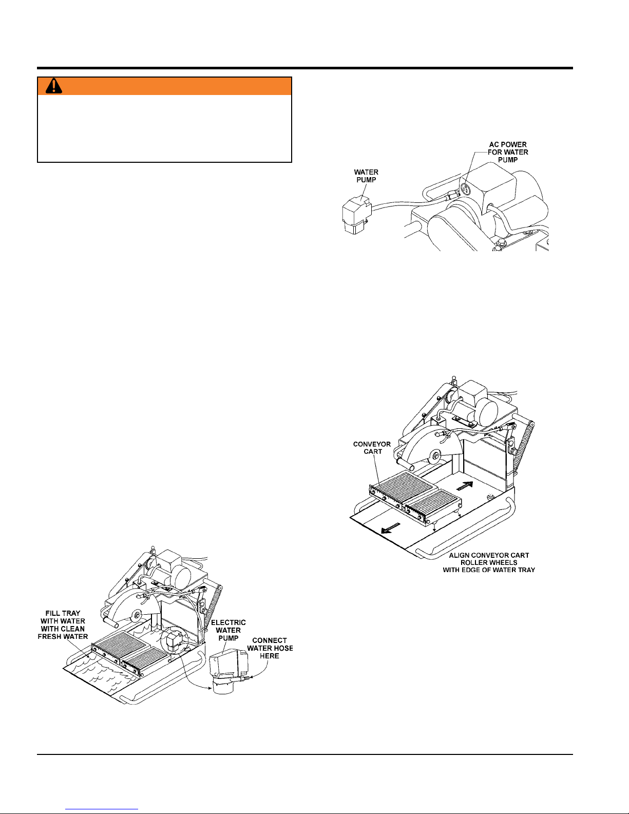
3. Attach the clear plastic water hose (Figure 5) coming
from the blade guard to the water pump.
6. Insert the water pump power plug into the outlet
receptacle on the electric motor conduit box as shown
in Figure 6.
Figure 6. Water Pump Power Connection
CONVEYOR CART PLACEMENT
1. Place the conveyor cart across the water tray as shown
in Figure 7. Align the wheels of the cart with the outer
edge of the water tray. Push the cart back and forth, it
should move freely in both directions.
4. Fill the water tray with clean fresh water. The water
pump intake must always be fully covered by water.
Also, keep the pump intake free of sludge, debris and
other materials that may accumulate in the tray.
5. Make certain that the water hose will not come in
contact with the blade or interfere with any moving
parts. The best location for the water pump/strainer
is between the splash shield and the rear of the water
tray. This will prevent some of the abrasive particles
from flowing through the pump.
Figure 7. Conveyor Cart Placement
Figure 5. Water Tray/Water Pump
PAGE 18 — MP1 SERIES MASONRY SAW • OPERATION AND PARTS MANUAL — REV. #2 (10/12/17)
SET-UP
BLADES
WARNING
Failure to thoroughly inspect the blade for
operational safety could result in damage to
the blades or the saw and may cause serious
injury to the user or others in the operating
area. Inspect the blade flanges and shaft for
damage before installing the blade.
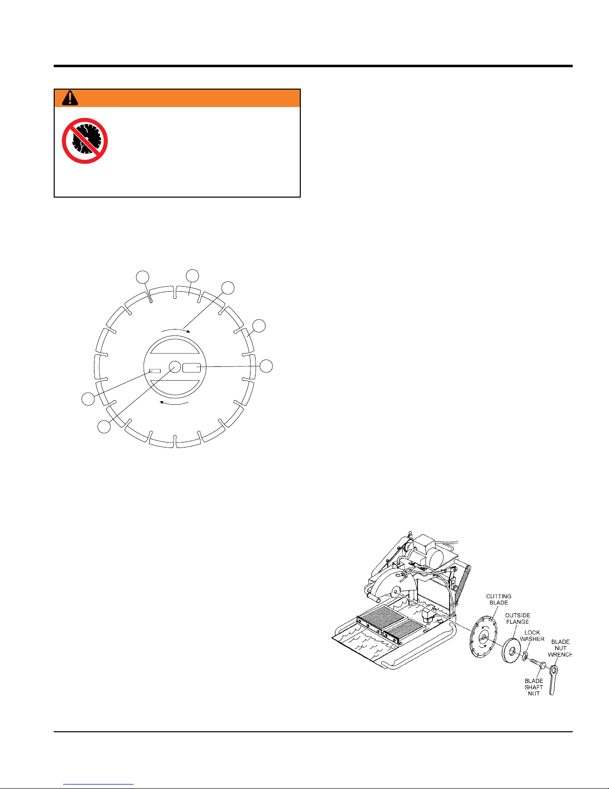
Blade Components
Diamond blades are recommended for your saw. Ask your
Multiquip dealer about your specific cutting application.
Figure 8 highlights the components of a diamond blade.
1
MAX.RPM
2
SPECIFICATIONS
3
4
5
4. Diamond Segment or Rim — Ensure that there are
no cracks, dings, or missing portions of the diamond
segment/rim. DO NOT use a blade that is missing
a segment or a portion of the rim. Damaged and/or
missing segments/rims may cause damage to your saw
and injury to the user or others in the operating area.
5. Specifications — Ensure that the blade specifications,
size, and diameter properly match up to the sawing
operation. Wet blades must have water to act as a coolant.
Utilizing a diamond blade not matched properly to the task
may result in poor performance and/or blade damage.
6. Arbor Hole — It is essential that the arbor hole
diameter properly matches the shaft arbor, and that it
is free from distortions. Correct blade flanges (collars)
must be used. The inside face of the flanges must be
clean and free of debris. An out of round arbor condition
will cause damage to the blade and the saw.
7. MAX RPM — This RPM reference is the maximum safe
operating speed for the blade selected. NEVER exceed
the max RPM on the diamond blade. Exceeding the MAX
RPM is dangerous, and may cause poor performance
and may damage the blade. All blades used must be
designed for the maximum spindle RPM.
7
6
Figure 8. Diamond Blade
1. Stress Relief Holes (Gullets) — Check the steel core
for cracks that may have propagated from the slots
and/or gullets. Cracks indicate extreme fatigue failure
and if sawing continues, catastrophic failure will occur.
2. Edge of the Steel Core — Check the diameter edge for
discoloration (blue oxidation) indicating an overheating
condition caused by insufficient cooling water/air.
Overheating of blades may lead to loss of core tension
and/or increase the possibility for blade failure. Check
to make sure the steel core’s width is uniform about
the rim of the blade, and not succumbing to an “under
cutting” condition brought about by highly abrasive
material or improper under cutting core protection.
3. Directional Arrow — Check to ensure that the blade is
oriented properly on the spindle for sawing. Reference the
directional arrow on the blade and place it so the direction
of rotation “downcuts” with the turn of the shaft.
Blade Installation
1. Use the blade nut wrench (Figure 9) supplied with
the saw to install the cutting blade
2. Ensure the capacity of the blade guard matches the
diameter of your cutting blade.
3. Using the blade nut wrench, remove the blade shaft
nut and outside blade flange. Install the cutting
blade onto the inside blade flange arbor. Re-install
the outside blade flange and blade shaft nut. Tighten
securely. DO NOT overtighten.
Figure 9. Blade Installation
MP1 SERIES MASONRY SAW • OPERATION AND PARTS MANUAL — REV. #2 (10/12/17) — PAGE 19
SET-UP
CONNECTING THE POWER
1. Place the power ON/OFF switch (Figure 11) in the OFF
position (down).
Figure 10. Power ON/OFF Switch
2. Connect an extension cord of adequate current carrying
capacity to the power plug on the electric motor.
3. MAKE CERTAIN that the correct size extension cord
is used. Undersized wires will burn out motors. Use
Table 4 to determine the correct extension cord size.
Table 4. Extension Cord Sizes
100 ft
(30.5 m)
Long
MOTOR
VOLTAGE
VAC
50 ft
(15. 2 m)
Long
75 ft
(22.9 m)
Long
1.5 HP 115 NO. 10 NO. 10 NO. 8
1.5 HP 230 NO. 14 NO. 14 NO. 14
2.0 HP 115 NO. 10 NO. 8 NO. 6
2.0 HP 230 NO. 12 NO. 12 NO. 12
DANGER
NEVER grab or touch a live
power cord with wet hands, the
possibility exists of electrical shock,
electrocution, and even death!
NEVER use a damaged or worn
extension cable when connecting
to a power source. Defective cables may cause damage
to the saw’s electric motor or electrical shock.
ALWAYS use a grounded (3-wire) extension cord
and MAKE CERTAIN that the motor is connected to
a properly grounded electric circuit. If possible use a
ground fault circuit interrupter to protect the operator
from possible electric shock.
Figure 11. Extension Cord Connection
PAGE 20 — MP1 SERIES MASONRY SAW • OPERATION AND PARTS MANUAL — REV. #2 (10/12/17)
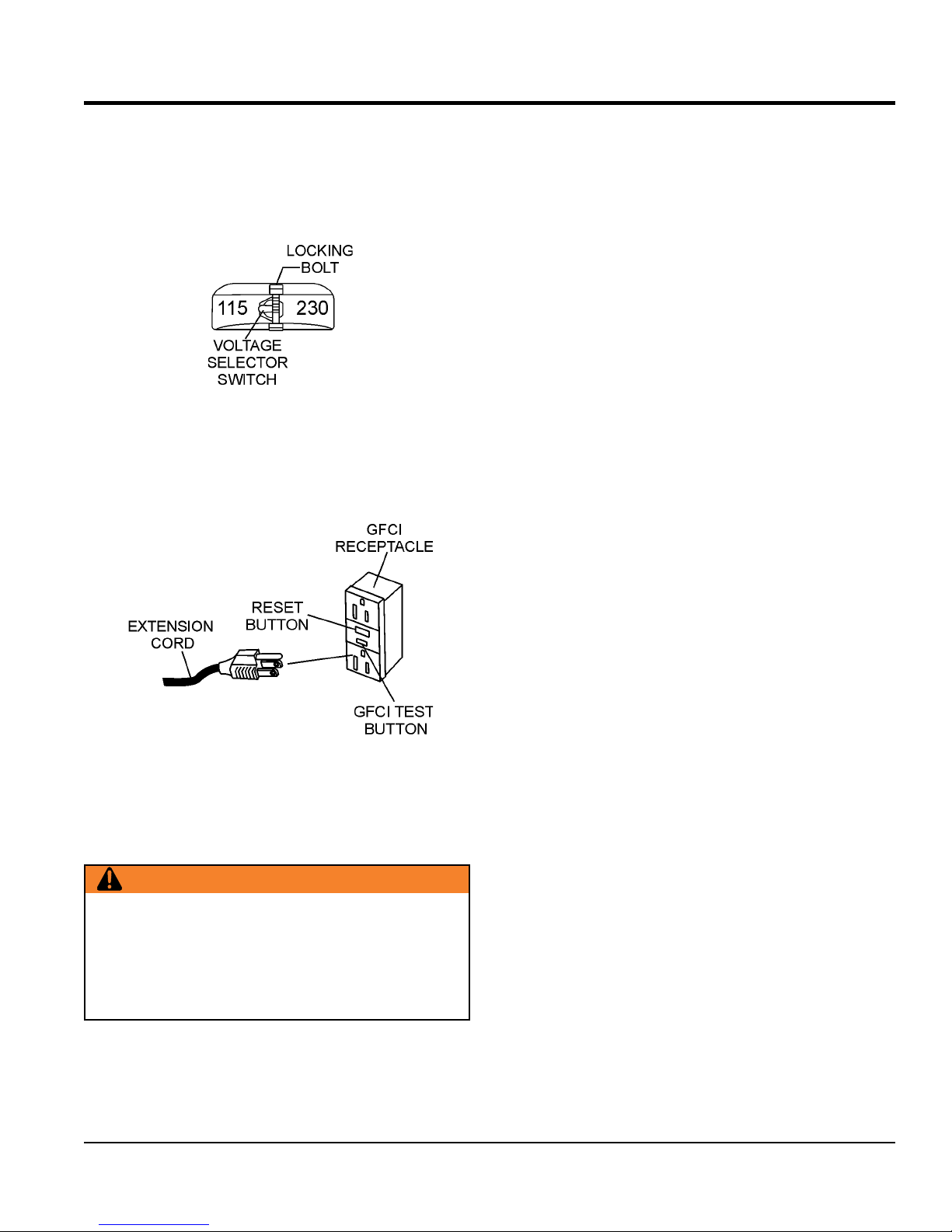
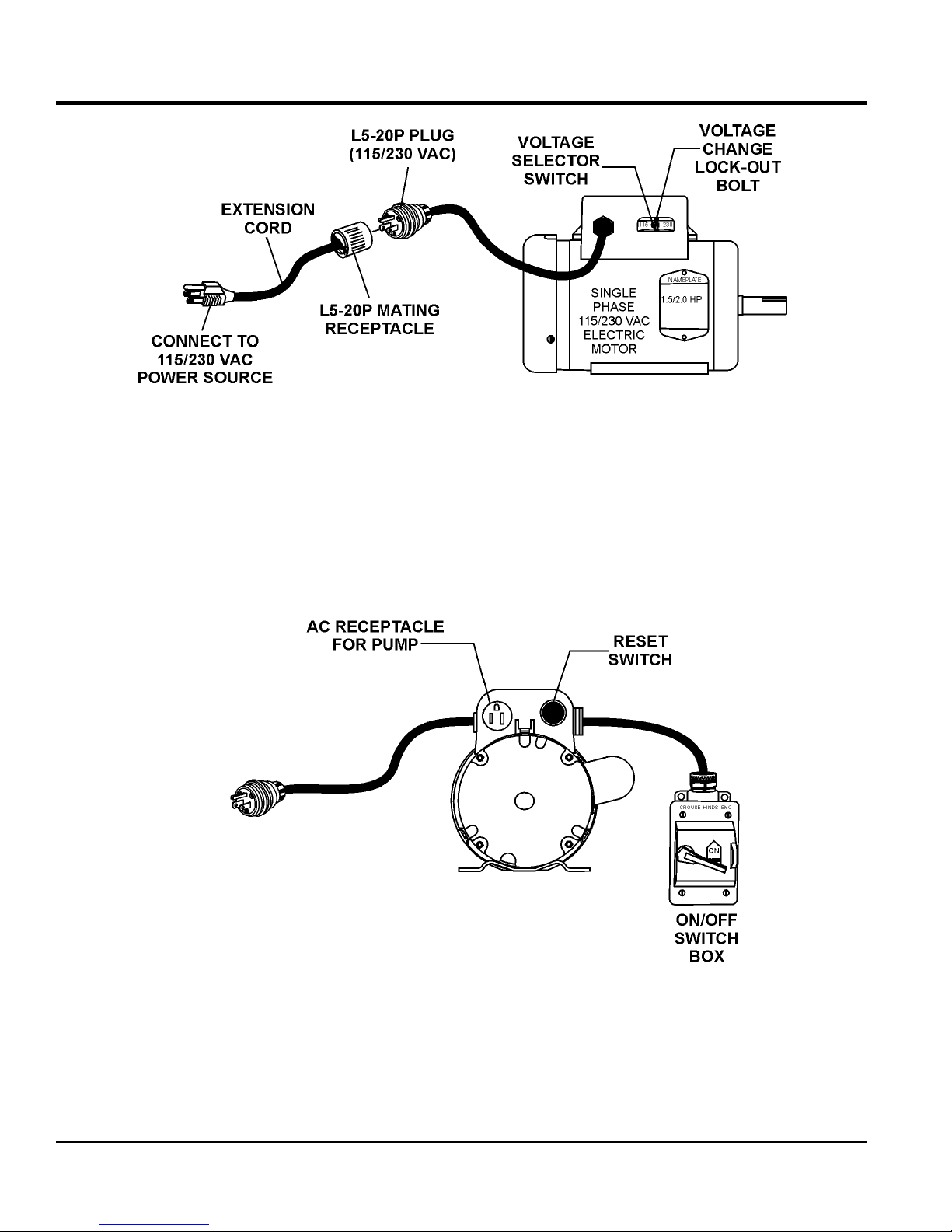
4. This unit is shipped from the factory with the voltage
selector switch (Figure 12) in the 115 VAC position. To
change the position of the switch from 115 VAC to 230
VAC, remove the locking bolt and place the switch in the
230 VAC position. Re-install the locking bolt to prevent
accidently flipping the switch.
Figure 12. Voltage Selector Switch
5. Plug the free end of the extension cord into an AC
power receptacle. Whenever possible use a GFCI
receptacle (Figure 13) to reduce the risk of electrical
shock.
SET-UP
Figure 13. GFCI Receptacle
6. The MP1 masonry saw is now ready for wet cutting.
The pre-setup procedures for electric models saws
only is now complete.
WARNING
Adherence to the OSHA 2017 Ruling governing
Occupational Exposure to Respirable Crystalline
Silica, requires that all sawing operations MUST BE
conducted with an integrated water delivery system
that feeds water to the blade.
MP1 SERIES MASONRY SAW • OPERATION AND PARTS MANUAL — REV. #2 (10/12/17) — PAGE 21
SET-UP
WARNING
Whenever cleaning, adjusting or lubricating any part
of the saw, MAKE CERTAIN to stop the engine and
disconnect the spark plug wire from the spark plug
ASSEMBLY (GASOLINE POWERED SAWS ONLY)
1. Remove the MP1 saw from its container and place it
on a suitable table or platform. Make sure the table
or platform can support the weight of the saw. The
saw platform should be rigid and stationary so that it
will not move, sag, or sway due to the vibrations and
movements of the saw.
2. If using the MP1 series support stand kit (P/N
TRAK14SS), attach stand to the under-side of the
water tray. Follow the instructions supplied with the
support stand kit when attaching it to the water tray.
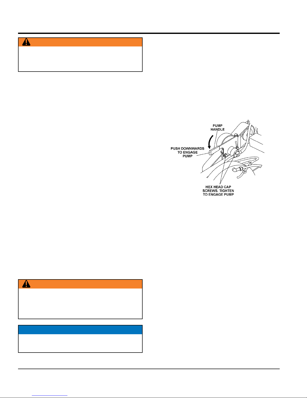
3. The gasoline powered saw uses a mechanical water
pump. This pump operates by drawing power from the
drive V-belts, and has been adjusted and locked for
wet cutting operation when shipped from the factory.
WET CUTTING (GASOLINE ONLY)
To connect the mechanical water pump to the drive V-belts
perform the following:
1. Loosen the 2 hex head cap screws (Figure 16) that
secure the pump mount bracket.
2. Push the pump handle downward to engage the
pump.
3. Tighten the 2 hex head cap screws that secure the
pump mount bracket.
4. Fill the water tray with clean fresh water. The water
pump intake (strainer) must always be fully covered
by water to operate effectively. Also, keep the pump
intake free of sludge, debris and other materials that
may accumulate in the tray.
5. Make certain that the water hose will not come in
contact with the blade or interfere with any moving
parts. The best location for the water pump/strainer
is between the splash shield and the rear of the water
tray. This will prevent some of the abrasive particles
from flowing through the pump.
WARNING
ALWAYS position the strainer in the water tray in
a manner that will allow the free movement of the
conveyor cart, and clearance from the cutting blade
and cutting action.
NOTICE
The mechanical water pump is shipped from the factory for
wet cutting applications.
Figure 14. Pump Engage
PAGE 22 — MP1 SERIES MASONRY SAW • OPERATION AND PARTS MANUAL — REV. #2 (10/12/17)
SET-UP
BEFORE STARTING
1. Read safety instructions at the beginning of manual.
2. Clean the saw, removing dirt and dust, particularly
the engine cooling air inlet, carburetor and air cleaner.
3. Check the air filter for dirt and dust. If air filter is dirty,
replace air filter with a new one as required.
4. Check carburetor for external dirt and dust. Clean with
dry compressed air.
5. Check fastening nuts and bolts for tightness.
ENGINE OIL CHECK
1. To check the engine oil level, place the saw on a secure
level surface with the engine stopped.
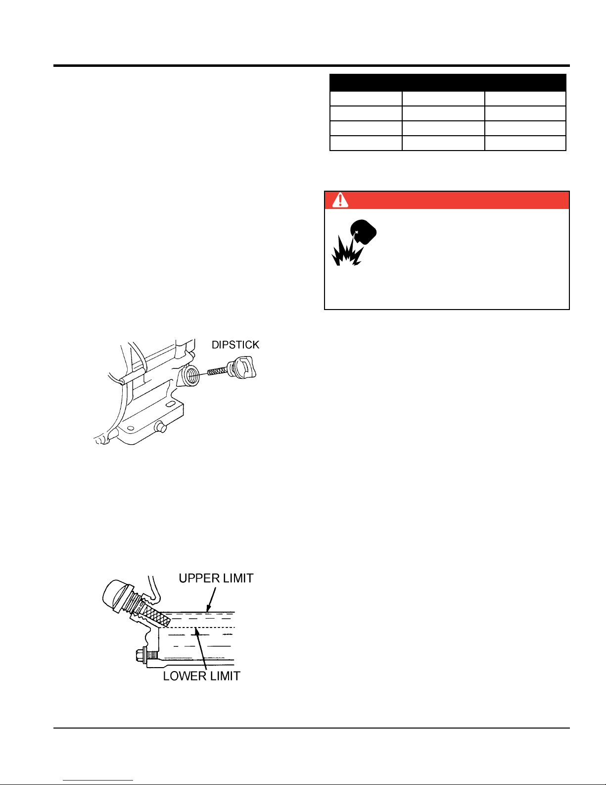
2. Remove the filler dipstick from the engine oil filler hole
(Figure 17) and wipe clean.
Table 5. Oil Type
Season Temperature Oil Type
Summer 25°C or Higher SAE 10W-30
Spring/Fall 25°C~10°C SAE 10W-30/20
Winter 0°C or Lower SAE 10W-10
FUEL CHECK
DANGER
EXPLOSIVE FUEL!
Motor fuels are highly flammable and can
be dangerous if mishandled. DO NOT
smoke while refueling. DO NOT attempt
to refuel the compactor if the engine is
hot or running.
1. Remove the gasoline cap located on top of fuel tank.
2. Visually inspect to see if the fuel level is low. If fuel is
low, replenish with unleaded fuel.
Figure 15. Engine Oil Dipstick (Removal)
3. Insert and remove the dipstick without screwing it into
the filler neck. Check the oil level shown on the dipstick.
4. If the oil level is low (Figure 18), fill to the edge of the
oil filler hole with the recommended oil type (Table 5).
Maximum oil capacity is 0.63 quarts (0.60 liters)
3. When refueling, be sure to use a strainer for filtration.
DO NOT top-off fuel. Wipe up any spilled fuel
immediately!
Figure 16. Engine Oil Dipstick (Oil)
MP1 SERIES MASONRY SAW • OPERATION AND PARTS MANUAL — REV. #2 (10/12/17) — PAGE 23
OPERATION
START-UP PROCEDURE (ELECTRIC MOTOR)
NOTICE
Read and fully understand this manual before
starting or attempting to operate the saw.
Before starting the saw’s electric motor
make sure that the Safety, General Information, and
Set-Up sections have been completed and understood.
DO NOT proceed until the above mentioned sections
have been completed.
WARNING
ALWAYS wear approved eye and hearing
protection before operating the saw.
WARNING
NEVER place hands or feet inside the belt
guard or blade guard while the motor is
running. ALWAYS shut the motor down
before performing any kind of maintenance
WARNING
NEVER lift the blade guard while the blade
is rotating. The possibility exists of severe
bodily harm if fingers or hands come in
contact with the rotating saw blade. Wait
for the blade to stop rotating before lifting
the blade guard.
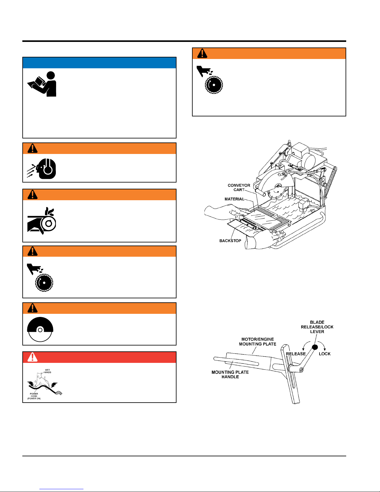
1. Place the material to be cut (Figure 17) on the conveyor
cart against the backstop
.
WARNING
NEVER place hands and fingers near
the cutting blade. The possibility exists of
severe bodily harm if hands and fingers
come in contact with rotating saw blade.
WARNING
ALWAYS ensure that the cutting blade has
been mounted correctly.
DANGER
Figure 17. Material Placement
2. Place the mounting plate release/lock lever (Figure
18) in the release position (pull back to release). When
releasing the lock, hold on to the mounting plate handle
to prevent the plate from rising rapidly, possibly causing
the saw to become unstable. Let the plate raise slowly.
NEVER touch a live power cord with wet
hands. The possibility exists of electrical
shock, electrocution which could cause
severe bodily harm, even death.
Figure 18. Mounting Plate Release/Lock Lever
PAGE 24 — MP1 SERIES MASONRY SAW • OPERATION AND PARTS MANUAL — REV. #2 (10/12/17)
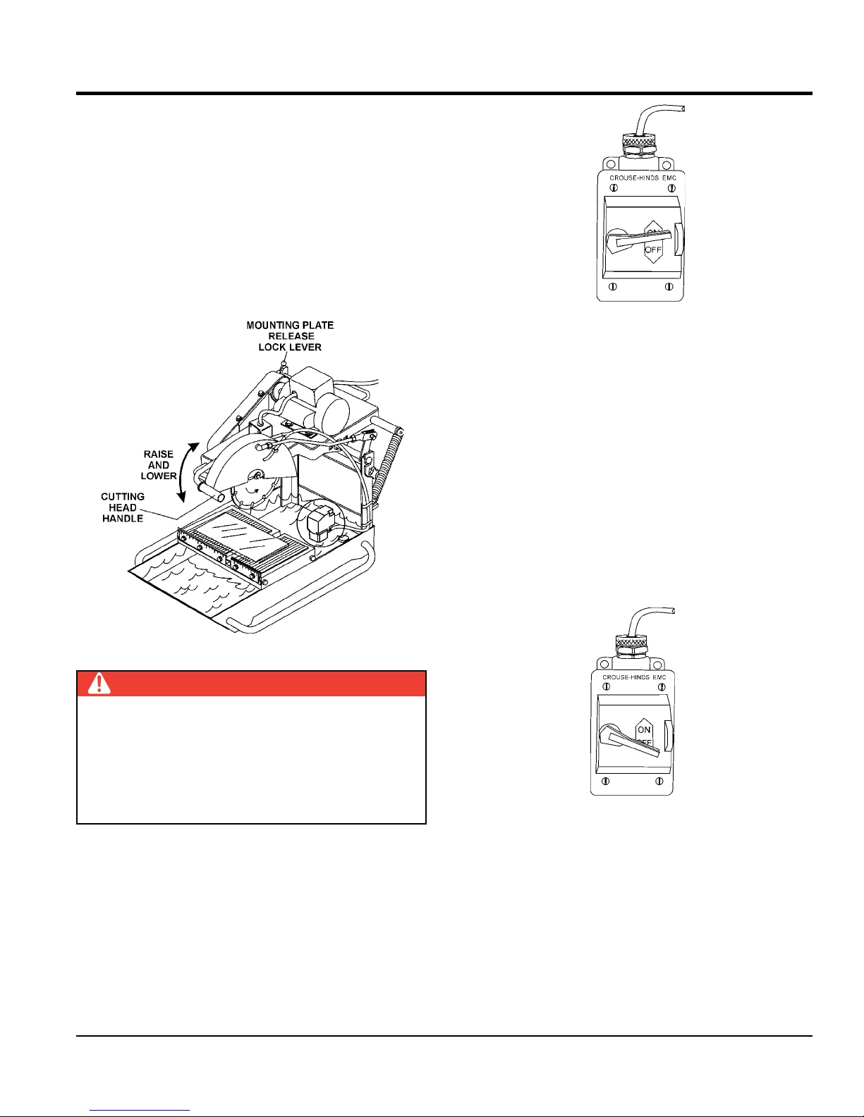
3. Adjust the cutting depth by pulling up or down on
the Cutting Head Handle (Figure 19). This saw is
designed, and is best utilized as a "Chop-Saw ". Once
the mounting plate release/lock lever is released, the
optimum cutting action is attained by using the Raise/
Lower Handle to rotate down onto the material to be
cut. Simultaneously the conveyor cart is moved slowly
forward to advance the material and cutting action.
A heavy-duty spring supports ergonomic return-to-
height action of the cutting head assembly.
OPERATION
Figure 20. Power ON/OFF Switch (ON)
5. Push the conveyor cart with the material, slowly and
evenly until the cut is complete. Move the cart back
and remove the cut pieces.
6. Avoid overloading the motor when cutting. However,
the electric motors are protected with a manual-reset
thermal overload switch that will turn the saw off if
the motor is overheated. In the event that the switch
is tripped, turn the "ON/OFF" switch to the "OFF"
position and allow the motor to cool before attempting
to restart.
Figure 19. Cutting Head Handle
DANGER
ALWAYS be alert to the fact that there is a rotating
blade on the saw and be extremely aware of your body
position — especially your hands in relationship to the
rotating blade. The possibility exists of severe bodily
harm or even death if your body comes in contact with
the rotating saw blade.
4. Turn the power ON/OFF switch (Figure 20) to the ON
position with the blade away from the material to be
cut, the cutting blade should begin to rotate. Before
cutting remember to follow all safety rules referenced
in this manual.
SHUT DOWN PROCEDURE
1. Place the power ON/OFF switch (Figure 21) in the OFF
position (down).
Figure 21. Power ON/OFF Switch (OFF)
2. Wait for the cutting blade to stop rotating.
3. Disconnect the saw's AC power cord from the power
source. NEVER leave the saw connected to a power
source when unattended. This will prevent accidental
starting.
4. Using a soft cloth, clean any excess debris or residue
that may have accumulated on the saw.
MP1 SERIES MASONRY SAW • OPERATION AND PARTS MANUAL — REV. #2 (10/12/17) — PAGE 25
5. Store saw in a clean dry location where it will be out
of the reach -of children.
OPERATION
START-UP PROCEDURE (ENGINE)
NOTICE
Read and fully understand this manual before
starting or attempting to operate the saw.
Before starting the saw’s electric motor
make sure that the Safety, General Information, and
Set-Up sections have been completed and understood.
DO NOT proceed until the above mentioned sections
have been completed.
WARNING
NEVER operate the saw in a confined
area or enclosed area structure that
does not provide ample free flow of
air
WARNING
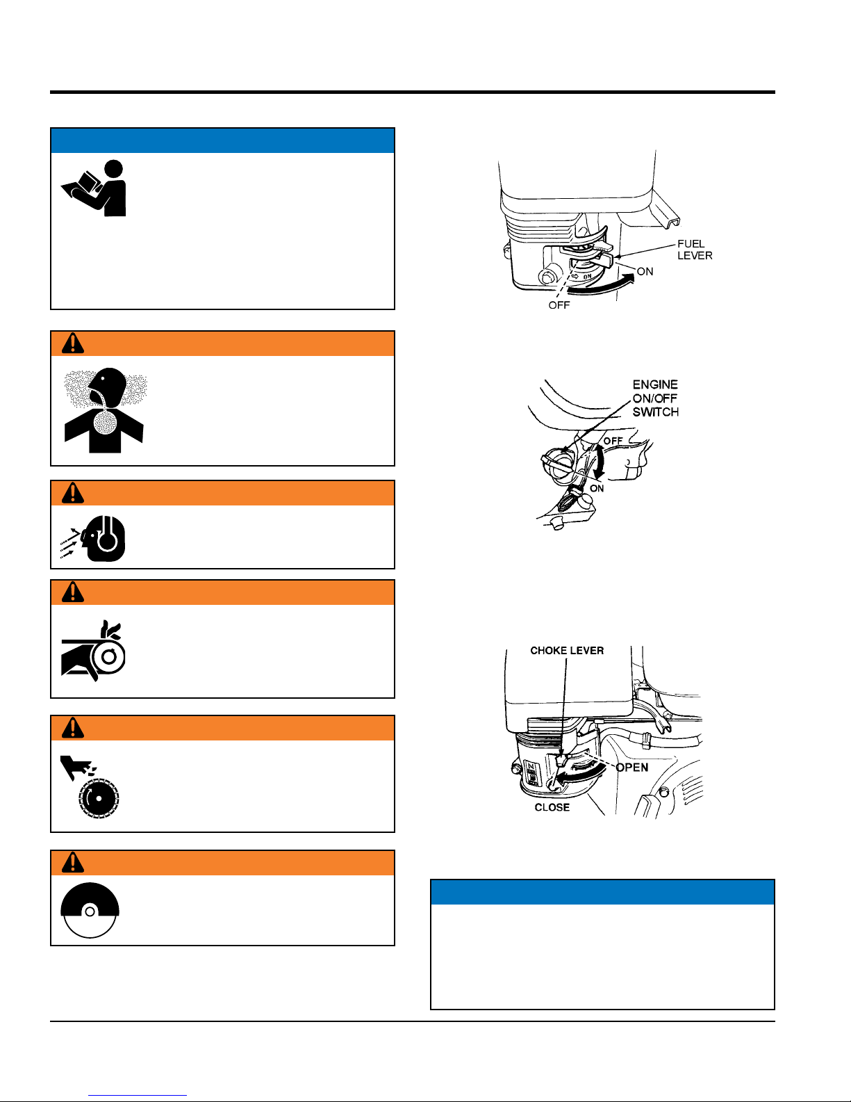
6. Place the engine fuel valve lever (Figure 22) to the
“ON” position.
Figure 22. Engine Fuel Valve Lever (ON Position)
7. Place the Engine ON/OFF switch (Figure 23) in the
"ON" position.
ALWAYS wear approved eye and hearing
protection before operating the saw.
WARNING
NEVER place hands or feet inside the belt
guard or blade guard while the motor is
running. ALWAYS shut the motor down
before performing any kind of maintenance
WARNING
NEVER place hands and fingers near
the cutting blade. The possibility exists of
severe bodily harm if hands and fingers
come in contact with rotating saw blade.
WARNING
ALWAYS ensure that the cutting blade has
been mounted correctly.
Figure 23. Engine ON/OFF Switch
Figure 24. osition)
8. Place the choke lever (Figure 25) in the “CLOSED”
position if starting a cold engine.
Figure 25. Choke Lever
NOTICE
The CLOSED position of the choke lever enriches the
fuel mixture for starting a COLD engine. The OPEN
position provides the correct fuel mixture for normal
operation after starting, and for restarting a warm
engine.
PAGE 26 — MP1 SERIES MASONRY SAW • OPERATION AND PARTS MANUAL — REV. #2 (10/12/17)
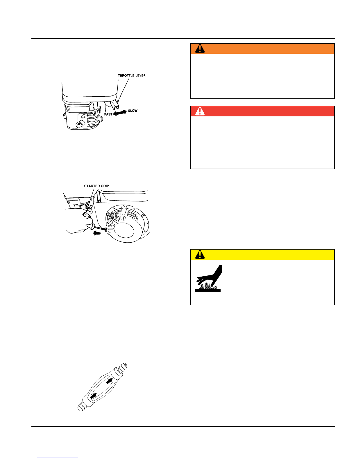
9.
Rotate the throttle lever (Figure 26) halfway between
fast and slow for starting. All cutting is done at full
throttle. The engine governor speed is factory set to
ensure optimum blade operating speeds
Figure 26. Throttle Lever
10. Grasp the starter grip (Figure 28) and slowly pull it out.
The resistance becomes the hardest at a certain position,
corresponding to the compression point. Pull the starter
grip briskly and smoothly for starting.
OPERATION
WARNING
ALWAYS cut with the saw at FULL THROTTLE.
Attempting to cut with the saw at less than full throttle
could cause the blade to bind or stop abruptly in the
slab resulting in serious injury to the operator or others
in the area.
DANGER
ALWAYS be alert to the fact that there is a rotating
blade on the saw and be extremely aware of your body
position — especially your hands in relationship to the
rotating blade. The possibility exists of severe bodily
harm or even death if your body comes in contact with
the rotating saw blade.
14. Push the conveyor cart with the material, slowly and
evenly until the cut is complete. Move the cart back
and remove the cut pieces.
Figure 27. Starter Grip
11. If the engine has started, slowly return the choke lever
(Figure 25) to the "OPEN" position. If the engine has
not started repeat steps 1 through 5.
12. Before the saw is placed into operation, run the engine
for several minutes. Check for fuel leaks, and noises
that would associate with a loose guards and/or covers.
13. Gradually move the engine throttle lever toward the
fast position. (All cutting should be done at full throttle)
Squeeze the water pump priming bulb (Figure 28)until
water begins to flow through the water lines. If the pump
is working correctly, the cutting blade should be covered
with a steady water mist. This will keep the blade cool.
15. Avoid overloading the engine when cutting. In the
event that the engine becomes overloaded, turn the
engine ON/OFF switch to the OFF position and allow
the engine to cool before attempting to restart.
STOPPING
CAUTION
AEngine components can generate extreme
heat. To prevent burns, DO NOT touch
these areas while the engine is running or
immediately after operations. NEVER operate
the engine with heat shields or heat guards
removed.
1. Set the engine throttle lever to slow speed and let
the engine idle for 3-5 minutes.
2. Turn the engine ON/OFF switch to the "OFF" position.
3. Place the fuel valve lever in the closed position.
4. Let the engine cool.
5. Using a soft cloth, clean any excess debris or residue
that may have accumulated on the saw.
Figure 28. Priming Bulb
MP1 SERIES MASONRY SAW • OPERATION AND PARTS MANUAL — REV. #2 (10/12/17) — PAGE 27
6. Store saw in a clean dry location where it will be out
of the reach of children.
 Loading...