

MQ Multiquip Mikasa MVH60, Mikasa MVH150, Mikasa MVH120 Service Manual

A
A
A
A
SERVICE
M
M
A
A
N
N
U
U
L
L
®
M
M
P
P
Updated 3/30/15
L
A
L
A
MAINTENANCE ○ DISASSEMBLY DIAGRAMS ○ TROUBLESHOOTING
V
V
T
T
H
H
E
E
6
0 ••
6
0
C
C
O
O
1
1
M
M
2
0 ••
2
0
P
P
C
C
1
1
T
T
5
0
5
0
O
O
R
R
Manual No. MVH60120150SM
S
S

CCAALLIIFFOORRNNIIAA
Proposition 65 Warning:
Engine exhaust and some of its constituents, and some dust created by power
sanding, sawing, grinding, drilling and other construction activities contains
chemicals known to the State of California to cause cancer, birth defects and
other reproductive harm.
Some examples of these chemicals are:
Lead and lead-based paint.
Crystalline silica from bricks.
Cement and other masonry products.
Arsenic and chromium from chemically treated lumber.
Your risk from these exposures varies, depending on how often you do this type
of work. To reduce your exposure to these chemicals: ALWAYS work in a well
ventilated area, and work with approved safety equipment, such as dust mask
that are specially designed to filter out microscopic particles.
Multiquip Inc. ◦ MVH 60 120 150 Plate Compactors ◦ Manual No. MVH60120150SM

CONTENTS
1. Tools・・・・・・・・・・・・・・・・・・・・・・・・・・・・・・・・・・・・・・・ 1
2. InspectionProce dure ・・・・・・・・・・・・・・・・・・・・・・・・・・ 2
3. Engine,OilandV-belt・・・・・・・・・・・・・・・・・・・・・・・・・・ 2
4. GeneralRule sforConductingService・・・・・・・・・・・・・ 3
5. DisassemblyandReassembly・・・・・・・・・・・・・・・・・・・・ 4
1. OperationSystem・・・・・・ ・・・・・・・・・・・・・・・・・・・・ 4
2. BasicMacine・・・・・・・・・・・・・・・・・・・・・・・・ ・・・・・・ 8
3. VibrationSystem・・・・・・・・・・・・・・・・・・・・・・・・・・・ 9
4. HandPumpSystem・・・・・・・・・・・・・・・・・・・・・・・・・ 19
6. PeriodicalIn spectionandMaintenanceWork・・・・・・・・21
7. TroubleShooting・・・・・・・・・・・・・・・・・・・・・・・・・・・・・・・26
8. WiringDiagra m・・・・・・・・・・・・・・・・・・・・・・・・・・・・・・・・・29
All information for MVH 60, 1
20, & 150 is provided by Manufacture
1. Wrench 10mm 1 2mm 13 mm 14mm 17mm 19mm 22mm 24mm 27mm
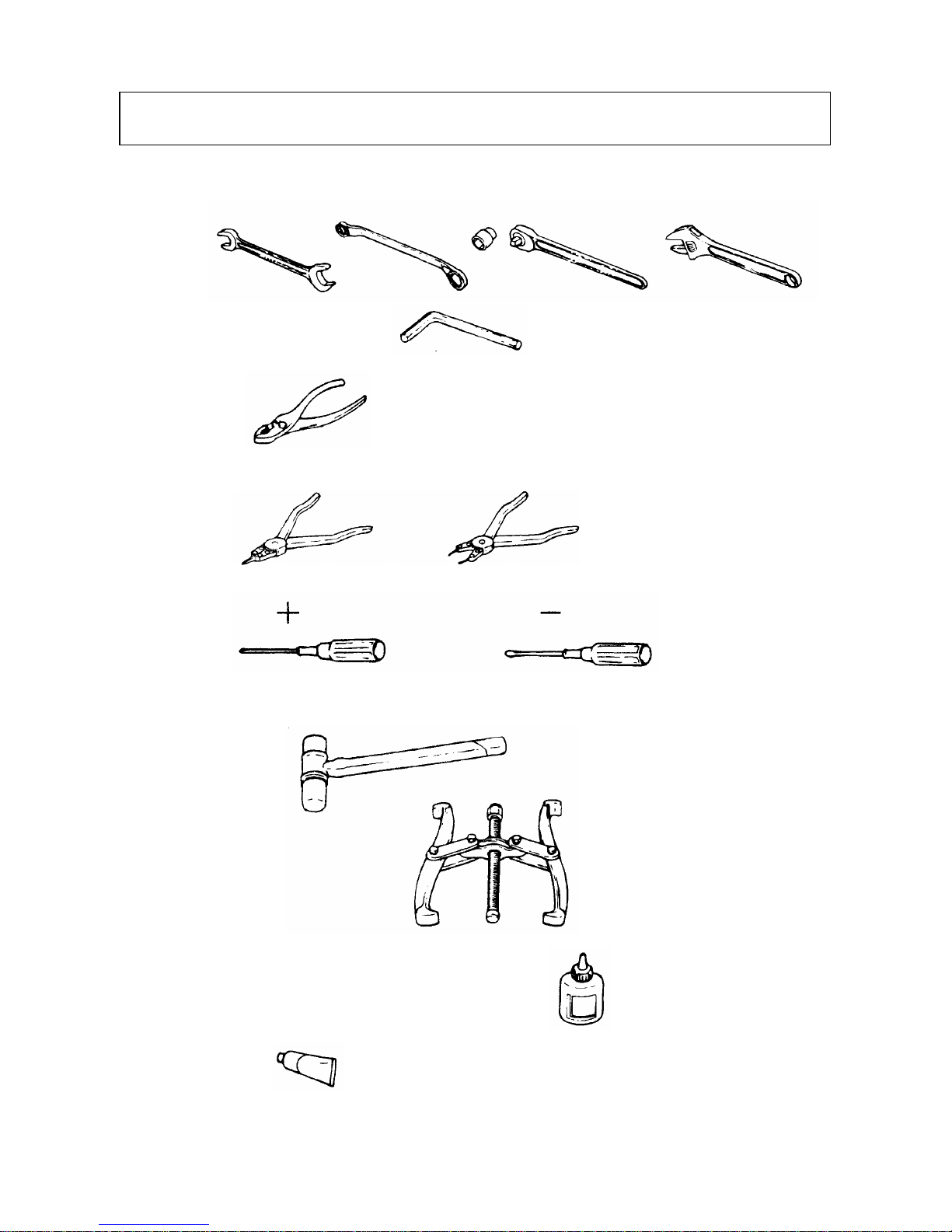
1.Tools
Offset wrench/Socket wrench/Adjustable wrench
2. Hexagonal wrench 3/16inch
5mm 8mm 10mm 14mm
3. Plier
4. External snap ring plier/Internal snap ring plier(bent type also use)
5. Screwdriver, flat and cross
6. Metal and plastic hammers
7. Pulley puller
8. Sealing compound (Locktite 242, 271 and 638)
9. Liquid gasket
10. Press tool
1

2. INSPECTION PROC E DURE
1. External appearance check
(1) Installation of parts (loosened screw, defective parts, etc.)
(2) Damage on machine
(3) Oil check (level an d contamination)
a. Engine oil (SA E1 0W-30 when shipped) (See Table 1 for the c ap acity)
b. Vibrator
c. Hydrau lic oil (T raveling)
(4) V
-belt for proper tension, damage, crack, hardening, etc.
(5) Isolation rubber for damage, crack, fatigue, hardening, etc.
2. Operating test
(1) Engine
Engine speed check (Max. set rpm and idling)
(2) Traveling
a.
Check selection of forward/reverse travel.
b.
Check speed of forward/reverse travel.
(3) C
heck for abnormal noise during operation.
Table 1
3.Engine, Oil and V-belt
Type MVH-R60 MVH-120 MVH-150
Mounted engine
HondaGX120 HondaGX160 RobinEH17 HondaGX200 RobinDY23(DS)
Set rpm (min-1)
3600 3600 3600 3600 3200
Fuel tank capacity (Liter)
2.5 3.6 3.6 3.6 3.2
Fuel consumption (L/h)
0.95 1.1 1.1 1.2 1.0
Engine oil capacity (L)
0.6 0.6 0.65 0.6 0.9
Vibrator oil capacity (L)
0.25 0.35 0.65 0.35 0.35
Lubrication oil in use Engine Oil SAE10W-30
Vibrator oil replacement
interval (hours)
200
Size and quantity of belt
RPF3320X1 RPF3320X1 PRF3320X1 RPF3350X1 RPF3340X1
Forward
0〜25 0〜23 0〜23 0〜25 0〜25
Compaction
speed (m/min)
Reverse
0〜25 0〜21 0〜21 0〜25 0〜25
Hydraulic oil Shell Stella #46 or equivalent
2

4. RULES FOR CONDUCTING SERVICE WORK
1. In order to avoid deficient reassembly, know normal status of installation before removing or
disassembling any part. Level check or replacement of vibrator oil should be carried out on level
groun
d.
2. Eac h tim e d isa ssem bly is m ade inv olv ing oil se a l, gasket, p acking, o-ring, lock w asher or the like, be
sure to replace them with new ones.
3. Mating surfaces of vibrator case and compaction plate should be sealed with liquid gasket (Clean
and de-grease the mating surfaces thoroug hly).
4. For tightening bolt and nut, use the specified standard torque and bonding agent (Loctite or the
like). For such bolt and nut that are not specified, see Table of Tightening Torque. (Before
coating with Loctite, clean the screws thoroughly.)
Note) All the screws in use with this machine are right handed.
Table of Tightening Torque (kgf-cm) Table 2
Screw diameter
Material
6mm 8mm 10mm 12mm 14mm 16mm 18mm 20mm
4T(SS41)
70 150 300 500 750 1,100 1,400 2,000
6-8T(S45C)
100 250 500 800 1,300 2,000 2,700 3,800
11T(SCM3)
150 400 800 1,200 2,000 2,900 4,200 5,600
In case counter
part is made from
aluminum
100 300〜350 650〜700
※For indication in SI Unit (International Unit System), use the conversion of 1kgf-cm=9.80665N-cm
5. Disassembly work should be conducted where it is free from dust.
6. Where bonding agent such as Loctite has been in use and screw is hard to loosen, heat it with torch
lamp or the like. Such heated bolt must be replaced with new one, which is of high-tension type as
spe
c
ified.
7. Use pro per too l in proper manner.
Hydraulichosetighteningtorque:Screwsize1/4380kgf‑cm
3
4
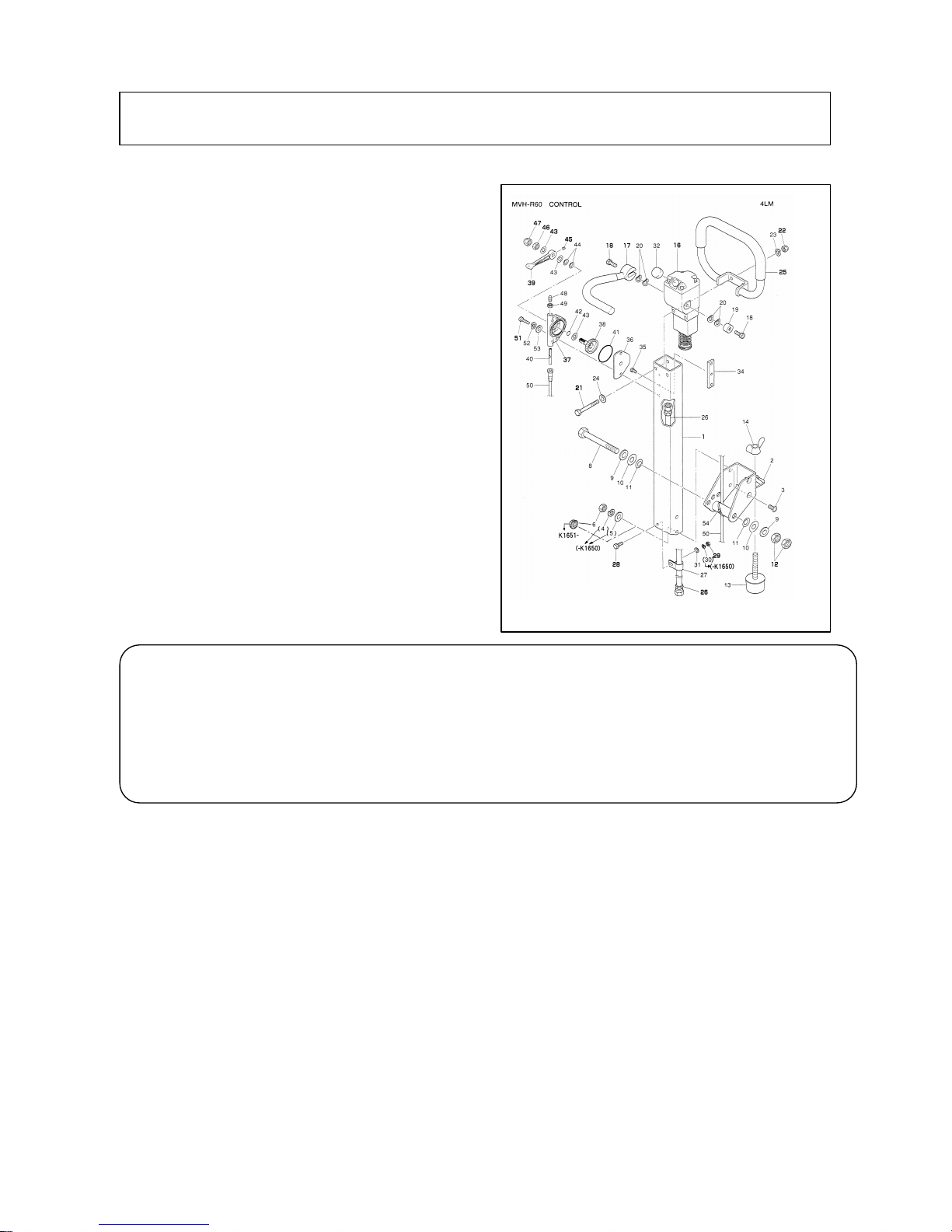
=Disassembled operation system=
5-1 OPEARTION SYSTEM (MVH-R60)
Disassembly
1. Removing two bolts (51) causes throttle body (37)
and throttle lever (39) to come off as an assembly.
Removing the double nut (46, 47) causes the
throttle lever to come off the throttle body. For
removing throttle lever off the machine, remove
the throttle wire (50) which has been screwed
down to the engine.
2. Removing bolt (18) causes the travel lever (17) to
come off hand pump (16).
3. Remove hydraulic hose (26) from the elbow of
vibrator shown in the drawing of disassembled
vibrator.
4. Removing four bolts (28) shown in the drawing allows to remove the handle (1) from base.
Reassembly:
Reassemble the system with its disassembly procedure reversed while observing below:
1. For installing the handle assembly (1) to the base, first have the four bolts (28) tightened only
lightly which are fixing the handle bracket (R) and (L) (26, 27) in the developed drawing, and after
adjusting resistance in handle operation by means of double nut (12), retighten them securely.
2. Have the throttle lever resistance adjusted with double nut (46, 47) before fixing the throttle lever
(39) with socket head set screw (45). The nut tightening torque is 120kgf-cm.
3. Set rpm for high speed side of engine (See Table 1) should be adjusted by means of engine set screw
on the engine side.
5. DISASSEMBLING/REASSEMBLING THE MVH-R60~150:
!Note
: Whenever hydraulic hose has been disconnected, apply blank plug to it for prevention of
any dust from entering.
Remove hydraulic hose clamp (27), its retainer bolt (28) and nut (29). Removing two
bolts (21) and nuts (22) allows to remove grip (25) and hand pump (16) from handle (1).
For VIBRO-CO MPACTOR MODEL MVR-R60
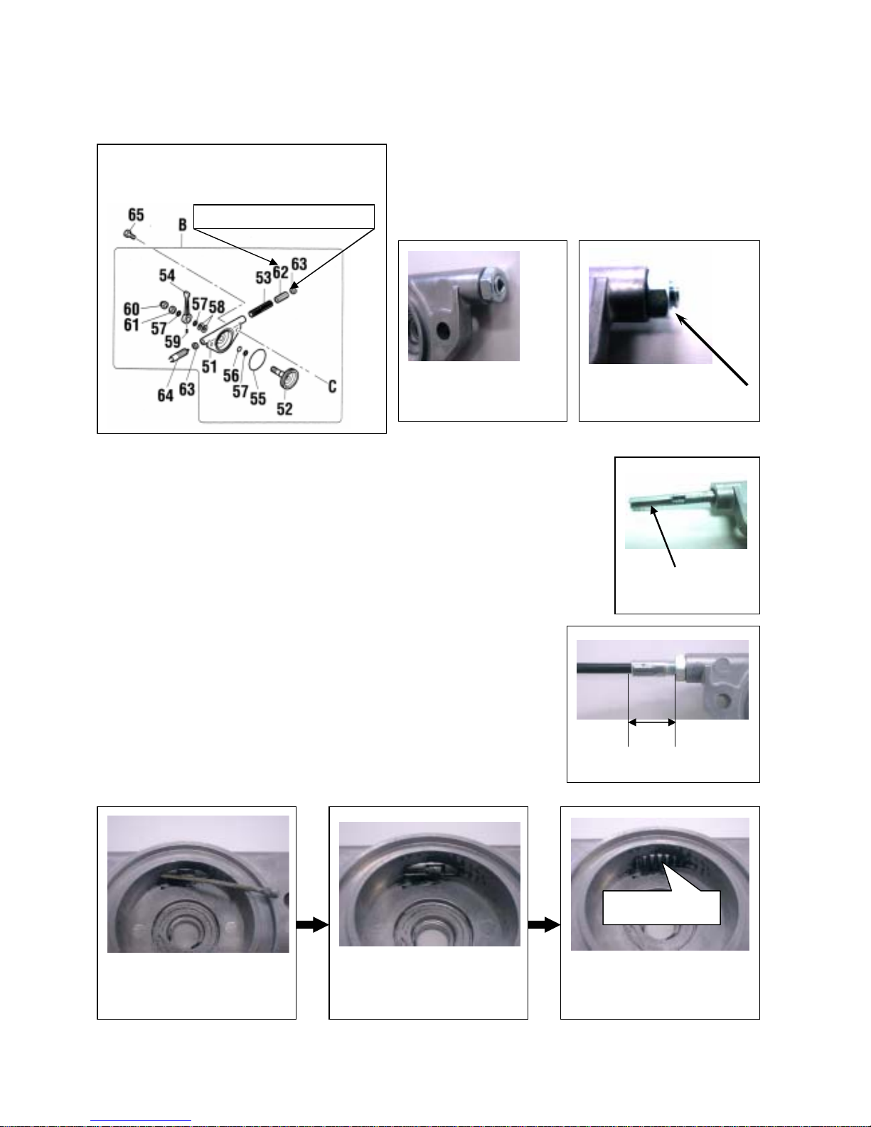
Reassembling the governor lever assembly:
The governor lever assembly should be totally disassembled except for hollow setscrew (62) and nut M8
(63) (See Fig.A).
<Note 1>
(Fig.-A)
Disassembling the Governor Lever Assembly:
Disassembled hollow setscrew (62) and thin nut M8 (63)
should be reassembled to be flush with eac h other as shown
in Photo B and C.
Parts not to disassemble.
Caution! channel
Photo D
20mm
Photo E
Photo B:
Properly done.
Photo C:
Correction required.
Reassembling Procedure:
1. Insert the slider (53) into throttle body (51) with its groove coming in the
back. (Photo D)
2. Install the outer governor wire (64). (Photo E)
(In case the end of inner governor wire should be bent, install inner and
outer wires together by taking measures of steps 3 and 4 below to get the
result as shown in Photo H.
)
3. Insert inner part of governor wire (64) through throttle body (51)
(Photo F and
G)
4. While pulling the end on inner wire which has come out of outer
part of governor wire, rotate it so that the gear teeth of slider is
visible. (Photo
H).
Apply grease.
Teeth should come to surface.
Photo H
Place head in groove.
Photo G
Insert inner part
Photo F
5
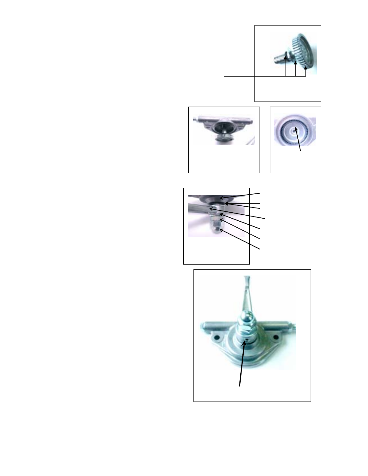
5.Assemble plain washer (57) and o-ring (56) to throttle gear (Photo I).
Photo I:
Throttle gear, etc.
Tooth face of throttle gear,
plain washer and o-ring should
be coated with grease.
6. Assemble throttle gear (52) to throttle body (51) as
follows:
Tr iangle mark
Photo K
Photo J:
Pull the inner part.
① Push-in the governor wire (inner) and shift the
slider (53) all the way to the back (Photo J).
② Install with triangle mark of the throttle gear
coming on top (Photo K)
7. Assemble throttle lever (54) to throttle body (51) (P
* Plain washers s
hoto L and M).
Throttle body(51)
Belleville spring (58) x 2
Plain washer M10(57)
Throttle lever(54)
Plain washer M10(57)
Nut M10(61)
Cap nut M10(60)
hould be installed fa cing each
* T ss of throttle lever should be adjusted
* Tu -in the hollow setscrew (59) to lock the throttle
fter assembling, throttle lever stops when it reaches
other.
ightne
with nut M10 and cap nut M10. To increase
resistance in the movement of throttle lever,
add a plain washer M10 on the back end.
Tighteningtorque:120kgf‑cm
Photo L:
Assembling the lever
Photo M:
crew Hollow sets
rn
lever to throttle gear .
A
top position as shown in Photo M. This is the position
for the maximum engine rpm.
6
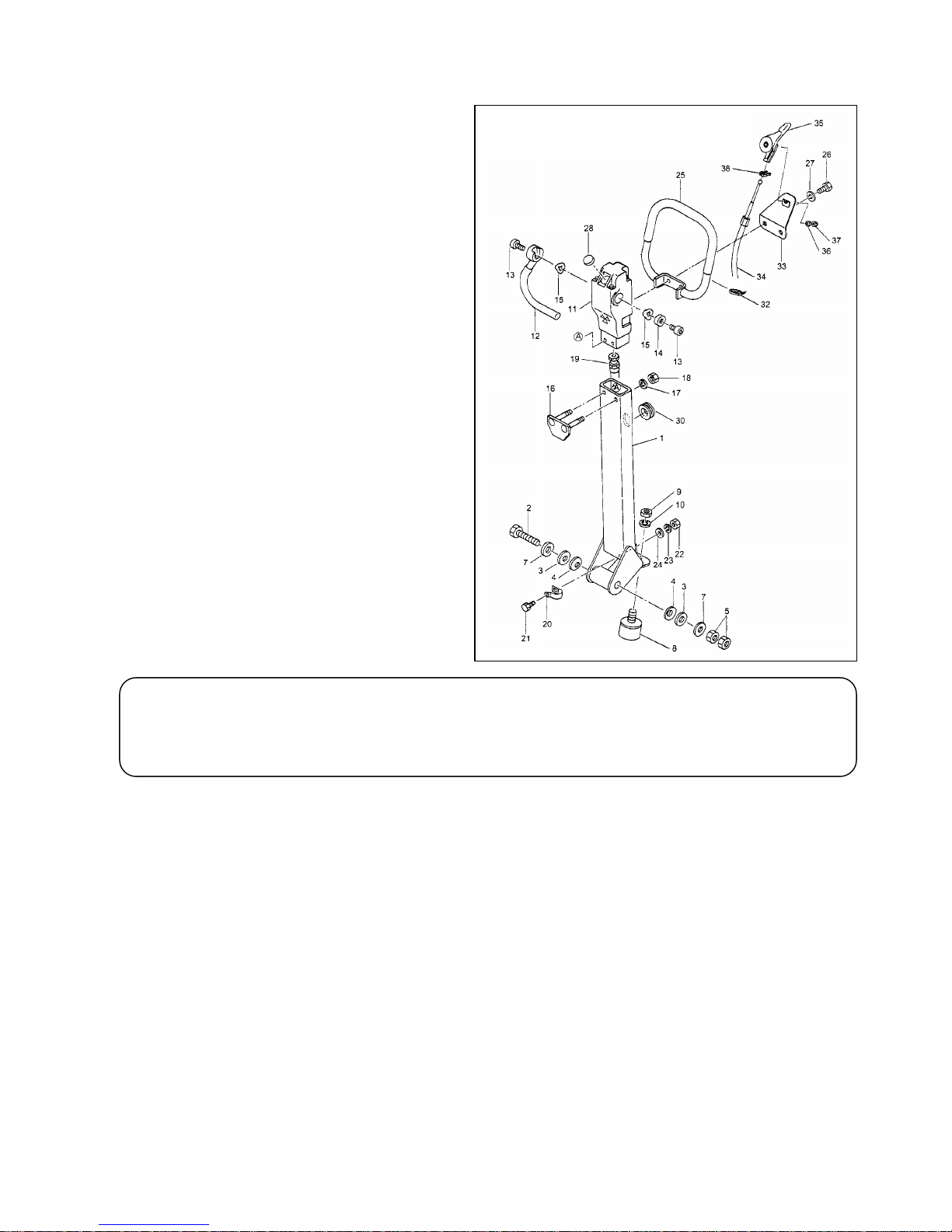
5-1 OPERATION SYSTEM (MVH-120)
Disassembling:
1. R emoving two bolts (26) allows to remove the
assembly of grip (25), lever bracket (33) and
throttle lever
(35).
Disassembled o peration system
Re
moving double nut (36, 37) causes throttle
lever (35) to come off the lever bracket (33).
To remove throttle lever from machine,
remove governor wire which has been screwe d
down to engine
.
2. Removing the bolt (13) allows to remove
travel lever (12) from hand pump (11).
3. Remove hydraulic hose (19) from the
connector (34) of vibrator shown in the
drawing of disassembled vibrato r
4. With the two handle root mounting double nuts (5) removed, taking off the bolt (2) allows to remove
the handle (1) from the base
.
! Note: After remo v ing hydraulic hos e , apply blind plug t o pr event any dust fr om entering.
Removing hose clamp (20), its mounting bolt (21), hand pump locking nut (18) and two
stud bolts (pump) (16) allows to remove the hand pump (11) from handle (1).
Reassembly:
Reassembly should be conducted with the d isassembling proced ure rev ersed while observing below:
1.
For installing the handle assembly (1) to the base, first lightly tighten the nut and bolt which have
been t
i
ghtening the guard hook side of the machine and adjust the resistance of handle movement by
means of double nut (5) before retightening
.
2. Resistance of handle movement should be adjusted with double nut (36, 37).
3. Set rpm of the engine on the high speed end should be adjusted on the engine side by means of engine
setscrew.
※
Disassembly and reassembly procedures for MVH-150 is identical to those of MVH-120.
7
 Loading...