

MQ Multiquip Mikasa MVC-80VH, Mikasa MVC-80VHW Parts Manual

OPERATION & PARTS MANUAL
SERIES
MODEL MVC-80VH/VHW
ONE-WAY PLATE COMPACTOR
(HONDA GASOLINE ENGINE)
Revision #0 (05/01/06)
To find the latest revision of this
publication, visit our website at:
www.multiquip.com
THIS MANUAL MUST ACCOMPANY THE EQUIPMENT AT ALL TIMES.
MVC-80VH/VHW PLATE COMPACTOR — PROPOSITION 65 WARNING
l
PAGE 2 — MVC-80VH/VHW PLATE COMPACTOR — OPERATION & PARTS MANUAL — REV. #0 (05/01/06)

NOTE PAGE
MVC-80VH/VHW PLATE COMPACTOR — OPERATION & PARTS MANUAL — REV. #0 (05/01/06) — PAGE 3

MVC-80VH/VHW PLATE COMPACTOR — TABLE OF CONTENTS
Multiquip —MVC-80VH/VHW
Plate Compactor
Proposition 65 Warning ............................................. 2
Table Of Contents ..................................................... 4
Parts Ordering Procedures ....................................... 5
Safety Message Alert Symbols .............................. 6-7
Rules For Safe Operation ...................................... 8-9
Operation and Safety Decals .................................. 10
Specifications (Compactor/Engine) ........................ 11
General Information ................................................ 12
Components (Plate Compactor) ............................. 13
Components (Engine) ............................................. 14
Inspection ........................................................... 15-16
Initial Start-Up .................................................... 17-18
Operation ................................................................ 18
Maintenance ...................................................... 19-21
Preparation For Long Term Storage ....................... 22
Troubleshooting (Engine) ................................... 23-24
Troubleshooting (Plate Compactor) ........................ 24
Explanation Of Codes In Remarks Column ............ 26
Suggested Spare Parts ........................................... 27
Honda GX160U1SM12 Engine
Cylinder Head Assembly ....................................38-39
Cylinder Barrel (Recoil) Assembly ..................... 40-41
Crankcase Cover Assembly ...............................42-43
Crankshaft Assembly .........................................44-45
Piston/Rings Assembly....................................... 46-47
Camshaft Assembly ........................................... 48-49
Recoil Starter .....................................................50-51
Fan Cover Assembly ..........................................52-53
Carburetor Assembly .........................................54-55
Air Cleaner Assembly......................................... 56-57
Muffler Assembly ...............................................58-59
Fuel Tank Assembly ...........................................60-61
Cooling Fan & Flywheel Assembly ..................... 62-63
Ignition Coil Assembly ........................................ 64-65
Control Assembly ...............................................66-67
Terms and Conditions Of Sale — Parts .................. 68
Component Drawings
Nameplate and Decals....................................... 28-29
Body Assembly .................................................. 30-31
Vibrator Assembly .............................................. 32-33
Sprinkler Assembly (Option) .............................. 34-35
Transport Wheel Assembly (Option) .................. 36-37
l
NOTE
Specification and part number
are subject to change without
notice.
PAGE 4 — MVC-80VH/VHW PLATE COMPACTOR — OPERATION & PARTS MANUAL — REV. #0 (05/01/06)

Effective: June 1st, 2005
Ordering parts has never been easier!
PARTS ORDERING PROCEDURES
Choose from three easy options:
Best Deal!
Order via Internet (Dealers Only):
Order parts on-line using Multiquip’s SmartEquip website!
■
View Parts Diagrams
■
Order Parts
■
Print Specification Information
Go to www.multiquip.com and click on
Order Par ts
to log in and save!
Order via Fax (Dealers Only):
All customers are welcome to order parts via Fax.
Domestic (US) Customers dial:
1-800-6-PARTS-7 (800-672-7877)
Order via Phone:
Non-Dealer Customers:
Contact your local Multiquip Dealer for
parts or call 800-427-1244 for help in
locating a dealer near you.
If you have an MQ Account, to obtain a
Username and Password, E-mail us at:
parts@multiquip.com.
To obtain an MQ Account, contact your
District Sales Manager for more information.
Use the
internet
and qualify for a 5% Discount
on
Standard orders
complete part numbers.*
Fax
your order in and qualify for a 3% Discount
on
Standard orders
complete part numbers.*
Domestic (US) Dealers Call:
1-800-427-1244
for all orders which include
for all orders which include
International Customers
their local Multiquip Representatives for
Parts Ordering information.
Note: Discounts Are Subject To Change
Note: Discounts Are Subject To Change
should contact
When ordering parts, please supply:
❒❒
❒
Dealer Account Number
❒❒
❒❒
❒
Dealer Name and Address
❒❒
❒❒
❒
Shipping Address (if different than billing address)
❒❒
❒❒
❒
Return Fax Number
❒❒
❒❒
❒
Applicable Model Number
❒❒
❒❒
❒
Quantity, Part Number and Description of Each Part
❒❒
NOTE
www.multiquip.com
Unless otherwise indicated by customer, all orders are treated as
within 24 hours. We will make every effort to ship
if received prior to 2PM PST.
WE ACCEPT ALL MAJOR CREDIT CARDS!
MVC-80VH/VHW PLATE COMPACTOR — OPERATION & PARTS MANUAL — REV. #0 (05/01/06) — PAGE 5
❒❒
❒
Specify Preferred Method of Shipment:
❒❒
✓
Fed Ex/UPS
■
■
■ Next Day
■
Stock Orders
✓ DHL
Priority One
Ground
Second/Third Day
✓
Truck
Standard Orders
Air Shipments
must be noted on fax or web order form.
the same day the order is received,
and will ship

MVC-80VH/VHW PLATE COMPACTOR — SAFETY MESSAGE ALERT SYMBOLS
FOR YOUR SAFETY AND THE SAFETY OF OTHERS!
Safety precautions should be followed
at all times when operating this
equipment. Failure to read and
understand the Safety Messages and
Operating Instructions could result in
injury to yourself and others.
This manual has been developed to
provide complete instructions for the
safe and efficient operation of the
NOTE
Before using this plate compactor, ensure that the
operating individual has read and understood all
instructions in this manual.
SAFETY MESSAGE ALERT SYMBOLS
The three (3) Safety Messages shown below will inform you
about potential hazards that could injure you or others. The
Safety Messages specifically address the level of exposure to
the operator, and are preceded by one of three words: DANGER,
MQ Mikasa
Compactor
manufacturer's instructions for data
relative to its safe operation.
MVC-80VH/VHW Plate
. Refer to the engine
HAZARD SYMBOLS
Potential hazards associated with the operation of an
MVC-80VH/VHW Plate Compactor
Hazard Symbols which appear throughout this manual, and
will be referenced in conjunction with Safety Message Alert
Symbols.
Engine exhaust gases contain
poisonous carbon monoxide. This gas
is colorless and odorless, and can
cause death if inhaled. NEVER operate
this equipment in a confined area or
enclosed structure that does not provide
ample free flow air.
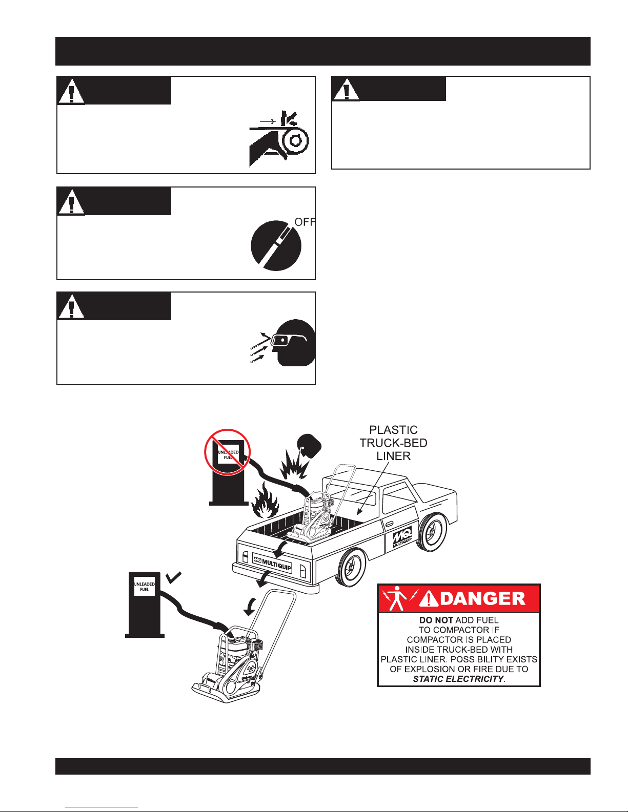
Gasoline is extremely flammable, and
its vapors can cause an explosion if
ignited. DO NOT start the engine near
spilled fuel or combustible fluids.
Lethal Exhaust Gases
WARNINGWARNING
WARNING
WARNINGWARNING
WARNINGWARNING
WARNING
WARNINGWARNING
Lethal Exhaust Gas Hazards
Explosive Fuel Hazards
will be referenced with
DANGERDANGER
DANGER
DANGERDANGER
You WILL be
if you DO NOT follow these directions.
WARNINGWARNING
WARNING
WARNINGWARNING
You CAN be KILLED or
you DO NOT follow these directions.
CAUTICAUTI
CAUTION
CAUTICAUTI
You CAN be
these directions.
KILLED
INJURED
if you DO NOT follow
or
SERIOUSLY INJURED
l
SERIOUSLY INJURED
if
DO NOT fill the fuel tank while the engine is running or
hot. DO NOT overfill tank, since spilled fuel could ignite if
it comes into contact with hot engine parts or sparks from
the ignition system. Store fuel in approved containers, in
well-ventilated areas and away from sparks and flames.
WARNINGWARNING
WARNING
WARNINGWARNING
Engine components can generate extreme
heat. To prevent burns, DO NOT touch
these areas while the engine is running or
immediately after operation. Never operate
the engine with heat shields or heat guards
removed.
WARNINGWARNING
WARNING
WARNINGWARNING
ALWAYS wear approved
protection when required.
Burn Hazards
Respiratory Hazards
respiratory
PAGE 6 — MVC-80VH/VHW PLATE COMPACTOR — OPERATION & PARTS MANUAL — REV. #0 (05/01/06)
MVC-80VH/VHW PLATE COMPACTOR — SAFETY MESSAGE ALERT SYMBOLS
CAUTIONCAUTION
CAUTION
CAUTIONCAUTION
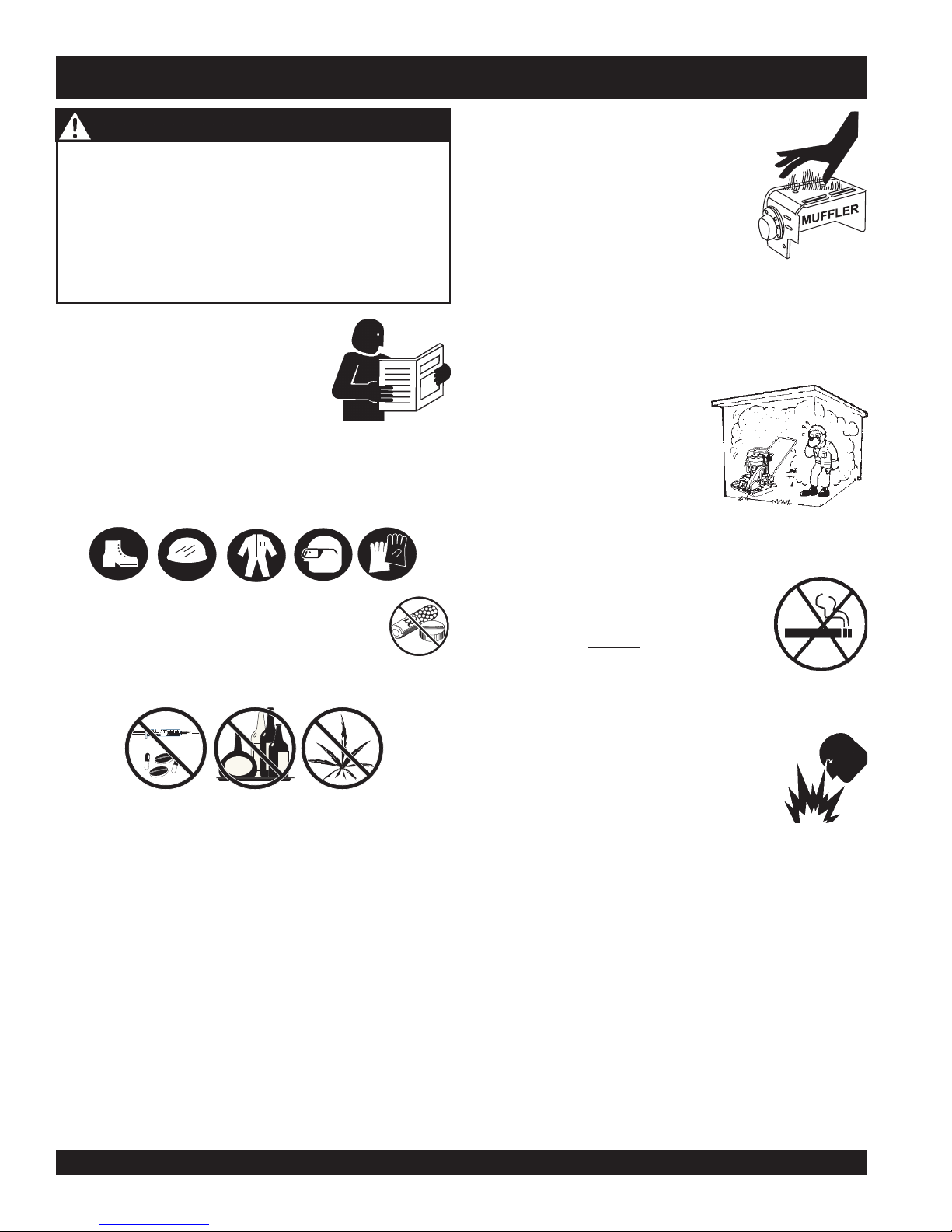
NEVER operate equipment with covers,
or guards removed. Keep fingers, hands,
hair and clothing away from all moving
parts to prevent injury.
CAUTIONCAUTION
CAUTION
CAUTIONCAUTION
ALWAYS place the engine ON/OFF switch
in the OFF position, when the plate
compactor is not in use.
CAUTIONCAUTION
CAUTION
CAUTIONCAUTION
ALWAYS wear approved eye and hearing
protection.
Rotating Parts Hazards
Accidental Starting Hazards
Eye and Hearing Hazards
CAUTIONCAUTION
CAUTION
CAUTIONCAUTION
Other important messages are provided throughout this
manual to help prevent damage to your equipment, other
property, or the surrounding environment.
Equipment Damage
Hazards
MVC-80VH/VHW PLATE COMPACTOR — OPERATION & PARTS MANUAL — REV. #0 (05/01/06) — PAGE 7
MVC-80VH/VHW PLATE COMPACTOR — RULES FOR SAFE OPERATION
■
WARNING - Read This Manual
Failure to follow instructions in this manual may lead to
Serious Injury
operated by trained and qualified personnel only! This
equipment is for industrial use only.
The following safety guidelines should always be used
when operating the Mikasa MVC-80VH/VHW Plate
Compactor.
Safety:
■
DO NOT operate or service this
equipment before reading this entire
manual.
■
This equipment should not be
operated by persons under 18 years of age.
■
NEVER operate this equipment without proper protective
clothing, shatterproof glasses, steel-toed boots and other
protective devices required by the job.
or even
Death
. This equipment is to be
NEVER touch the hot exhaust manifold,
muffler or cylinder. Allow these parts to
cool before servicing engine or
generator.
■
High Temperatures – Allow the engine
to cool before adding fuel or performing
service and maintenance functions.
Contact with
■
The engine of this plate compactor requires an adequate
free flow of cooling air. NEVER operate the plate
compactor in any enclosed or narrow area where free
flow of the air is restricted. If the air flow is restricted it
will cause serious damage to
the plate compactor or engine
and may cause injury to people
and property. Remember the
compactor's engine gives off
DEADLY gases.
■
ALWAYS refuel in a well-ventilated area, away from
sparks and open flames.
hot!
components can cause serious burns.
■
■
NEVER operate this equipment when not
feeling well due to fatigue, illness or taking
medicine.
■
NEVER operate the plate compactor under the influence
or drugs or alcohol.
■
■
NEVER disconnect any
These devices are intended for operator safety.
Disconnection of these devices can cause severe injury,
bodily harm or even death! Disconnection of any of these
devices will void all warranties.
■
NEVER use accessories or attachments, which are not
recommended by Multiquip for this equipment. Damage
to the equipment and/or injury to user may result.
■
Manufacturer does not assume responsibility for any
accident due to equipment modifications. Unauthorized
equipment modification will void all warranties.
■
Whenever necessary, replace nameplate, operation and
safety decals when they become difficult read.
■
ALWAYS check all the bolts on the plate compactor for
tightness.
"emergency or safety devices"
.
l
■
■
■
■
■
ALWAYS use extreme caution when
working with flammable liquids. When
refueling, stop the engine and allow it to
cool. DO NOT smoke around or near the
machine. Fire or explosion could result
from fuel vapors, or if fuel is spilled on a
hot engine.
NEVER operate the plate compactor in
an explosive atmosphere or near
combustible materials. An explosion or
fire could result causing severe
bodily
harm or even death.
Topping-off to filler port is dangerous, as it tends to spill
fuel.
ALWAYS store the plate compactor in a clean, dry
location out of the reach of children.
NEVER run engine without air cleaner. Severe engine
damage may occur.
NEVER leave the plate compactor unattended, turn off
engine.
CAUTION must always be observed while servicing this
plate compactor. Rotating parts can cause injury if
contacted.
PAGE 8 — MVC-80VH/VHW PLATE COMPACTOR — OPERATION & PARTS MANUAL — REV. #0 (05/01/06)

MVC-80VH/VHW PLATE COMPACTOR — RULES FOR SAFE OPERATION
Loading and Unloading (Crane):
■
Before lifting, make sure that machine parts (hook and
vibration insulator) are not damaged and screws are not
loosened or lost.
■
ALWAYS make sure crane or lifting device has been
properly secured to the hook of guard frame on compactor.
■
NEVER lift the machine while the engine is running.
■
Use adequate lifting cable (wire or rope) of sufficient
strength.
■
Use one point suspension hook and lift straight upwards.
■
NEVER allow any person or animal to stand underneath
the machine while lifting.
■
Try not to lift machine to unnecessary heights.
Transporting
■
ALWAYS shutdown engine before transporting.
■
Tighten fuel tank cap securely and close fuel cock to
prevent fuel from spilling.
■
Drain fuel when transporting compactor over long
distances or bad roads.
■
ALWAYS tie down the compactor during transportation
by securing the compactor's guard frame with rope.
Maintenance Safety:
■
■
■
■
■
■
■
Emergencies:
■
■
■
NEVER lubricate components or attempt service on a
running machine.
ALWAYS allow the machine a proper amount of time to
cool before servicing.
Keep the machinery in proper running condition.
Fix damage to the machine immediately and always
replace broken parts.
Dispose of hazardous waste properly. Examples of
potentially hazardous waste are used motor oil, fuel and
fuel filters.
DO NOT use food or plastic containers to dispose of
hazardous waste.
DO NOT pour waste, oil or fuel directly onto the ground,
down a drain or into any water source.
ALWAYS know the location of the
nearest
ALWAYS know the location of the
nearest
In emergencies
of the nearest phone or
Also know the phone numbers of the nearest
ambulance, doctor
information will be invaluable in the case of an
emergency.
fire extinguisher
first aid kit
always
.
.
know the location
keep a phone on the job site
and
fire department
.
. This
MVC-80VH/VHW PLATE COMPACTOR — OPERATION & PARTS MANUAL — REV. #0 (05/01/06) — PAGE 9

MVC-80VH/VHW PLATE COMPACTOR — OPERATION AND SAFETY DECALS
Machine Safety Decals
The MVC-80VH/VHW Plate Compactor is equipped with a number of safety decals. These decals are provided for operator safety
and maintenance information. The illustration below shows these decals as they appear on the machine. Should any of these decals
become unreadable, replacements can be obtained from your dealer.
CAUTION !
"
READ OWNER’S SERVICE MANUAL BEFORE OPERATING OR
SERVICING THIS MACHINE.
"
ALWAYS KEEP UNAUTHORIZED, INEXPERIENCED,
UNTRAINED PEOPLE AWAY FROM THIS MACHINE.
"
MAKE SURE ALL SAFETY DEVICES ARE OPERATIONAL
BEFORE THIS MACHINE IS STARTED. BE SURE ENGINE
IS TURNED OFF AND SPARK PLUGS ARE DISCONNECTED
BEFORE SERVICING THE MACHINE OR COMING IN
CONTACT WITH ANY MOVING PART. IF EQUIPMENT IS
POWERED BY AN ELECTRIC MOTOR, DISCONNECT
ELECTRICAL PLUG.
NEVER LEAVE MACHINE UNATTENDED WHEN OPERATING.
"
ALWAYS STOP ENGINE AND ALLOW ENGINE TO COOL
BEFORE ADDING FUEL OR OIL.
NPA-329
*
P/N: 920203290
Serial No.
Model No.
CONTACT
MQ PARTS DEPT.
l
P/N: 920101410
P/N: 920201580
NPA-989
P/N: 920203989
P/N: 920105070
*
PAGE 10 — MVC-80VH/VHW PLATE COMPACTOR — OPERATION & PARTS MANUAL — REV. #0 (05/01/06)
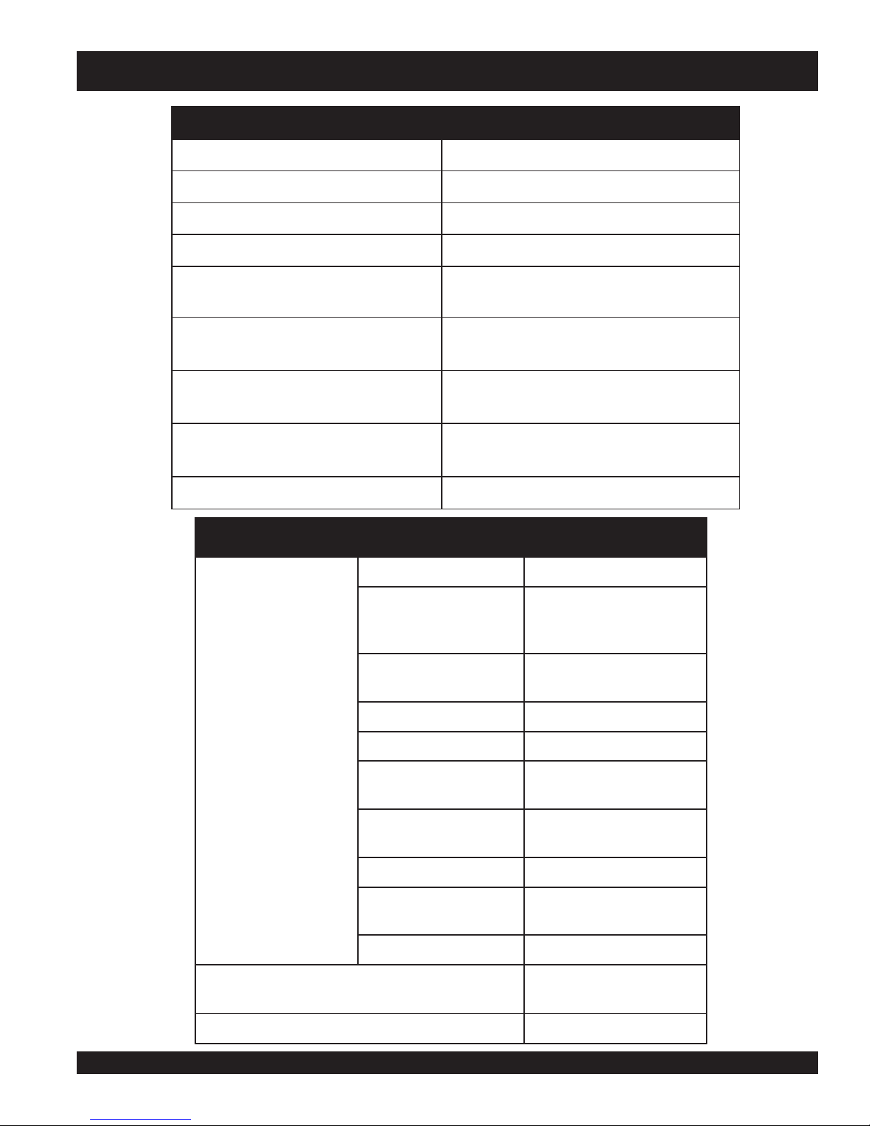
MVC-80VH/VHW PLATE COMPACTOR — SPECIFICATIONS
)rotcapmoC(snoitacificepS.1ELBAT
sledoMWHV08-CVM/HV08-CVM
ecroFlagufirtneC)gk723,1(.sbl829,2
ebmuN)zH39(nim/snoitarbiv006,5
snoitarbiVfor
deepSgnilevarT)nim/sretem22(nim/.tf27
)WxL(eziSetalP
HxWxL(snoisnemiDllarevO
)
)HV(thgieWgnitarepO
)WHV(thgieWgnitarepO
yticapaCknaTretaW
)ylnOledoMWHV(
noitcapmoCfOaerA.xaM)rh/m.
ledoM21MS1U061XGADNOH
epyT
.ni7.71x4.22
mm054x075
.ni4.93x7.71x6.63
)mm0001x054x039(
08(.sbl161
).gk5.
).gk5.88(.sbl381
)sretil0.31(.tq8.31
qs066(.rh/.tf.qs728,6
)enignE(snoitacificepS.2elbaT
elgniS,ekorts4delooc-riA
latnoziroH,VHO,rednilyC
enignEenilosaGtfahS
SXeroB
ekort
tnemecalpsiD)ni-uc9.9(cc361
tuptuOxaM.M.P.R0063/.P.H5.5
enignE
yticapaCknaTleuF
leuF
yticapaCliOebuL)stq36.0(sretil06.
tnoCdeepS
noisnemiD
)HxWxL(
thgieWteNyrD
MVC-80VH/VHW PLATE COMPACTOR — OPERATION & PARTS MANUAL — REV. #0 (05/01/06) — PAGE 11
dohteMlor
dohteMgnitratStratSlioceR
403(
.ni8.1x.ni7.2
)mm54xmm86(
sno
llag.S.U59.0.xorppA
)sretil6.3(
elibomotuAdedaelnU
enilosaG
thgiew-ylFlagufirtneC
epyT
.ni2.31x2.41x021
)mm533x263x
).gK84.01(sbl1.32
A
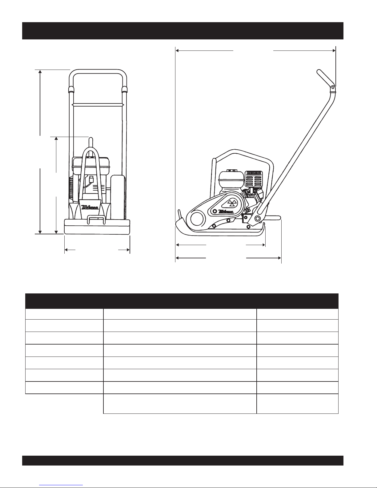
MVC-80VH/VHW PLATE COMPACTOR — DIMENSIONS
E
F
A
B
C
D
E
F
B
D
C
SNOISNEMID.3ELBAT
RETTELECNEREFER NOITPIRCSED )mm(.niNOISNEMID
l
htdiW )mm054(sehcni71
htgneLetalP )mm075(sehcni22
)thgirpUeldnaH(thgieH )mm0001(sehcni63
)thgirpUeldnaH(htgneL )mm026(sehcni42
)derewoLeldnaH(htgneL )mm039(sehcni73
)ylnOrotcapmoC(thgieH )mm095(sehcni32
snoisnemiDgnippihS
sehcni62x91x53
)mm076x084x068(
PAGE 12 — MVC-80VH/VHW PLATE COMPACTOR — OPERATION & PARTS MANUAL — REV. #0 (05/01/06)

MVC-80VH/VHW PLATE COMPACTOR — GENERAL INFORMATION
Definition of Plate Compactor
The Mikasa MVC-80VH/VHW is a walk behind, plate compactor
designed for the compaction of sand, mixed soils and asphalt.
This plate compactor is a powerful compacting tool capable of
applying a tremendous force in consecutive high frequency
vibrations to a soil surface. Its applications include compacting
for road, embankments and reservoirs as well as backfilling for
gas pipelines, water pipelines and cable installation work.
Vibratory Plates
The vibratory plates of the MVC-80VH/VHW produce low
amplitude high frequency vibrations, designed to compact
granular soils and asphalt.
The resulting vibrations cause forward motion. The engine and
handle are vibration isolated from the vibrating plate.
Frequency/Speed
The compactor's vibrating plate has a frequency range between
5600 vpm (vibrations per minute). The travel speed of the
compactor is approximately 72 ft./minute (22 meters/minute).
Engine
The Mikasa MVC-80VH/VHW Plate Compactor is equipped with
a Honda GX160U1SM12 gasoline engine.
Controls
Before starting the MVC-80VH/VHW Plate Compactor identify
and understand the function of the controls and components.
MVC-80VH/VHW PLATE COMPACTOR — OPERATION & PARTS MANUAL — REV. #0 (05/01/06) — PAGE 13
MVC-80VH/VHW PLATE COMPACTOR — COMPONENTS (COMPACTOR)
1
10
4
9
3
2
WATER TANK
(MVC-80VHW ONLY)
8
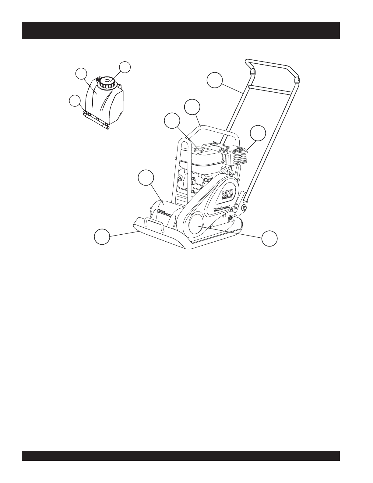
Figure 1. Plate Compactor Controls
Figure 1 shows the location of the basic controls and components
of the MVC-80VH/VHW Plate Compactor. The function of each
control is described below:
1. Water Tank Cap (VHW Only) – Remove this cap to add
water to the water tank.
2. Fuel Tank Cap – Remove this cap to add fuel.
3. Lifting Bale – When lifting of the compactor is required
either by forklift, crane etc., tie rope or chain around this
lifting point.
4. Handle Bar – When operating the compactor use this
handle bar to maneuver the compactor.
5. Gasoline Engine – This plate compactor uses a HONDA
GX160U1SM12 engine. Refer to the HONDA owner's
manual for engine information and related topics.
l
6. Belt Cover – Remove this cover to gain access to the
V-belts. NEVER run the compactor without the V-belt cover.
If the V-belt cover is not installed, the possibility exists that
your hand may get caught between the V-belt and clutch,
causing serious injury and bodily harm.
7. Vibrating Plate – A flat, open plate made of durable cast
iron construction used in the compacting of soil.
8. Vibration Case – Encloses the eccentric, gears and
counter weights.
9. Water Shut-Off Valve (VHW only) – Turn this valve
downward to let water flow from the water tank to the water
tube.
10. Water Tank (VHW only) – Holds 13.8 quarts of water
(removable, no tools required).
5
67
PAGE 14 — MVC-80VH/VHW PLATE COMPACTOR — OPERATION & PARTS MANUAL — REV. #0 (05/01/06)
MVC-80VH/VHW PLATE COMPACTOR — COMPONENTS ( ENGINE)
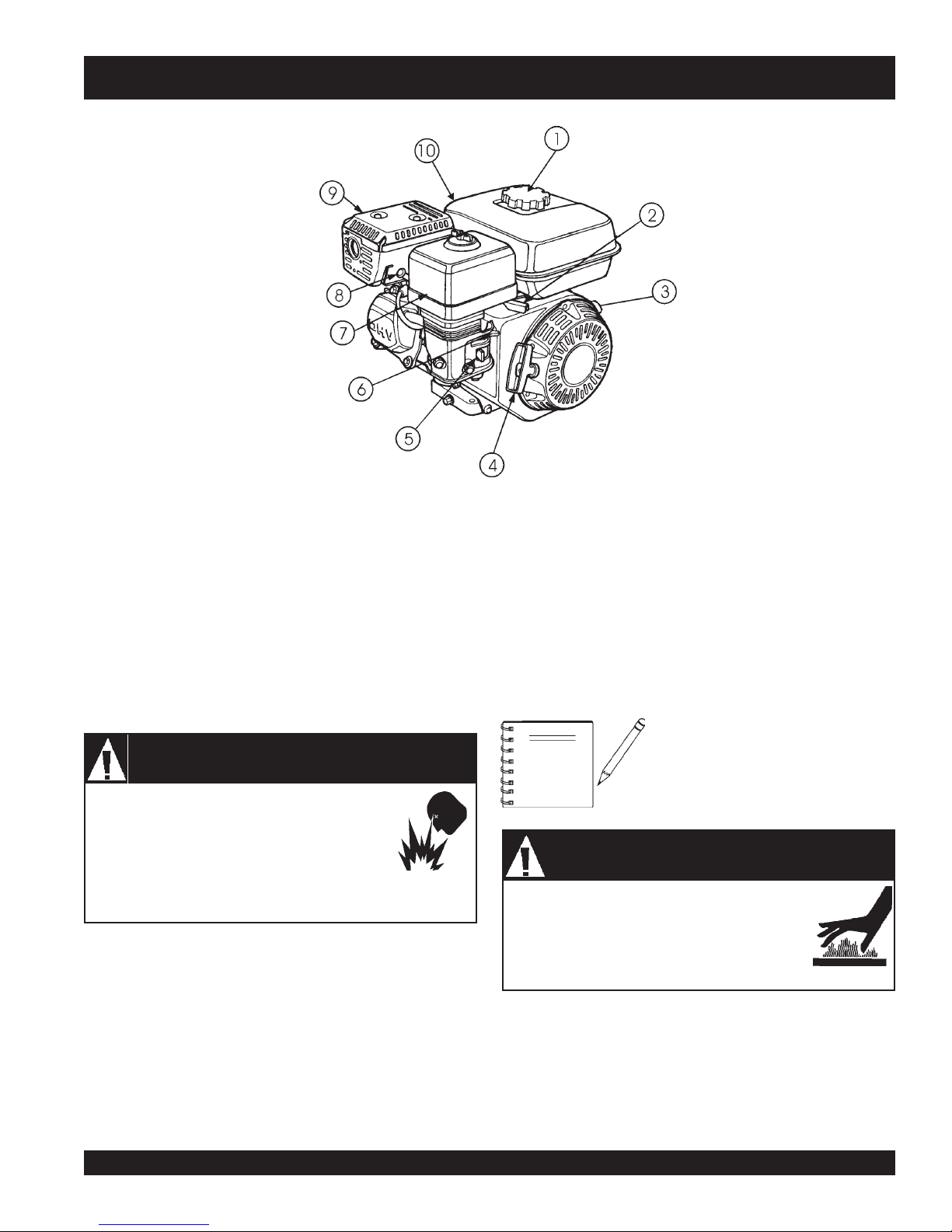
Figure 2. Engine Controls & Components
ENGINE COMPONENTS
The engine (Figure 2) must be checked for proper lubrication and
filled with fuel prior to operation. Refer to the manufacturers Engine
manual for instructions & details of operation and servicing.
1. Fuel Filler Cap – Remove this cap to add unleaded
gasoline to the fuel tank. Make sure cap is tightened
securely. DO NOT over fill.
DANGERDANGER
DANGER
DANGERDANGER
Adding fuel to the tank should be done only when
the engine is stopped and has had an opportunity
to cool down. In the event of a fuel spill, DO NOT
attempt to start the engine until the fuel residue has
been completely wiped up, and the area surrounding the engine
is dry.
2. Throttle Lever – Used to adjust engine RPM speed (lever
advanced forward -
FAST
).
3. Engine ON/OFF Switch – ON position permits engine
starting, OFF position stops engine operations.
4. Recoil Starter (pull rope) – Manual-starting method. Pull
the starter grip until resistance is felt, then pull briskly and
smoothly.
Explosive Fuel Hazard
SLOW
, lever back toward operator -
5. Fuel Valve Lever – OPEN to let fuel flow, CLOSE to stop
the flow of fuel.
6. Choke Lever – Used in the starting of a cold engine, or in
cold weather conditions. The choke enriches the fuel
mixture.
7. Air Cleaner – Prevents dirt and other debris from entering
the fuel system. Remove wing-nut on top of air filter
cannister to gain access to filter element.
NOTE
Engine components can generate extreme heat.
To prevent burns, DO NOT touch these areas while
the engine is running or immediately after
operating. NEVER operate the engine with the
muffler removed.
8. Spark Plug – Provides spark to the ignition system. Set
spark plug gap to 0.6 - 0.7 mm (0.028 - 0.031 inch) Clean
spark plug once a week.
9. Muffler – Used to reduce noise and emissions.
10. Fuel Tank – Holds unleaded gasoline. For additional
information refer to engine owner's manual.
WARNINGWARNING
WARNING
WARNINGWARNING
Operating the engine without an air
filter, with a damaged air filter, or a filter
in need of replacement will allow dirt
to enter the engine, causing rapid
engine wear.
Burn Hazard
MVC-80VH/VHW PLATE COMPACTOR — OPERATION & PARTS MANUAL — REV. #0 (05/01/06) — PAGE 15
MVC-80VH/VHW PLATE COMPACTOR — INSPECTION
Before Starting
1. Read safety instructions at the
beginning of manual.
2. Clean the compactor, removing
dirt and dust, particularly the
engine cooling air inlet, carburetor
and air cleaner.
3. Check the air filter for dirt and dust. If air filter is dirty, replace
air filter with a new one as required.
4. Check carburetor for external dirt and dust. Clean with dry
compressed air.
5. Check fastening nuts and bolts for tightness. Loosened
screws or bolts due to vibration, could lead to unexpected
accident.
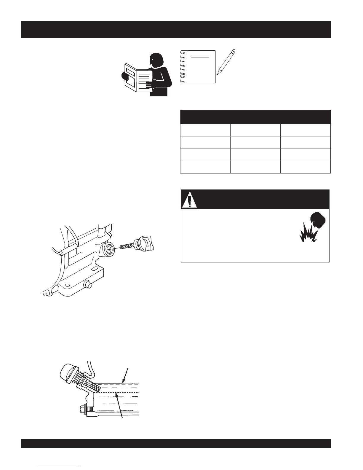
Engine Oil Check
1. To check the engine oil level, place the pump on secure
level ground with the engine stopped.
2. Remove the filler dipstick from the engine oil filler hole
(Figure 3) and wipe clean.
NOTE
Adding fuel to the tank should be done only when
the engine is stopped and has had an opportunity
to cool down. In the event of a fuel spill, DO NOT
attempt to start the engine until the fuel residue has
been completely wiped up, and the area surrounding the engine
is dry.
The Oil Alert System will automatically
stop the engine before the engine falls
below safe limits. Always be sure to
check the engine oil level prior to
starting the engine.
epyTliO.4elbaT
nosaeS erutarepmeT epyTliO
remmuS rehgiHroC°52 03-W01EAS
llaF/gnirpS C°01~C°52 02/03-W01EAS
retniW rewoLroC°0 01-W01EAS
DANGERDANGER
DANGER
DANGERDANGER
Explosive Fuel Hazard
Fuel Check
Figure 3. Engine Oil Dipstick (Removal)
3. Insert and remove the dipstick without screwing it into the filler
neck. Check the oil level shown on the dipstick.
4. If the oil level is low (Figure 4), fill to the edge of the oil filler
hole with the recommended oil type (Table 4). Maximum oil
capacity is 0.63 quarts (0.60 liters)
Figure 4. Engine Oil Dipstick (Oil Level)
PAGE 16 — MVC-80VH/VHW PLATE COMPACTOR — OPERATION & PARTS MANUAL — REV. #0 (05/01/06)
l
1. Remove the gasoline cap located on top of fuel tank.
2. Visually inspect to see if the fuel level is low. If fuel is low,
replenish with unleaded fuel.
3. When refueling, be sure to use a strainer for filtration. DO
NOT top-off fuel. Wipe up any spilled fuel
immediately!
MVC-80VH/VHW— INSPECTION
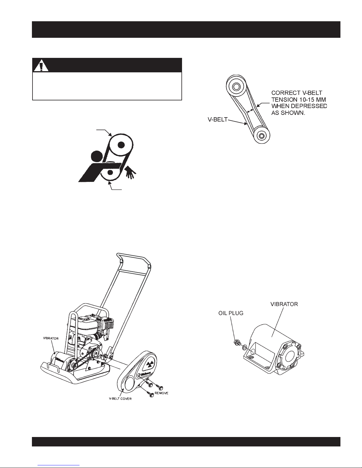
V-Belt Check
CAUTICAUTI
CAUTION
CAUTICAUTI
NEVER attempt to check the V-belt with the engine running.
Severe injury can occur of your hand (Figure 5) gets caught
between the V-belt and the clutch. Always use safety gloves.
CLUTCH
PULLEY
Figure 5. V-Belt Hazard
V-Belt Check
VIBRATOR
PULLEY
2. The V-belt tension is proper if the V-belt bends 10 to 15 mm
3. A loose V-belt will decrease the power transmission output,
4. If the V-belt becomes worn or loose, replace it.
(Figure 7) when depressed with finger at midway between
the clutch and vibration pulley shafts.
Figure 7. V-Belt Tension
causing reduced compaction and premature wear of the
belt.
1. To check the V-belt tension, remove the three bolts that
secure the belt cover to the frame as shown in Figure 6.
Vibrator Oil Check
1. Place the MVC-80VH/VHW plate compactor horizontally on
a flat surface. Make sure the compactor is level when checking the oil in the vibrator assembly.
2. Check vibrator oil level by removing the plug (vibrator oil gauge)
as shown in Figure 8. The oil level should be up to the oil plug.
The vibrator holds 140 cc (approximately 1 pint). IMPORTANT,
if oil is required, replace using only SAE10W-30 motor oil.
Figure 8. Vibrator Oil Plug
Figure 6. V-Belt Cover Removal
MVC-80VH/VHW PLATE COMPACTOR — OPERATION & PARTS MANUAL — REV. #0 (05/01/06) — PAGE 17
MVC-80VH/VHW— INITIAL START-UP
CAUTICAUTI
CAUTION
CAUTICAUTI
DO NOT attempt to run the compactor until
the Safety and Initial Start-up sections have
been read and understood.
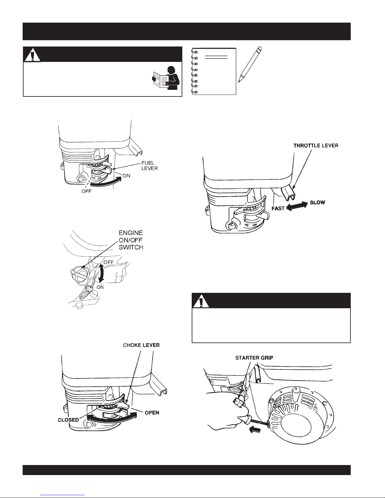
1. Place the
2. Place the
position.
fuel valve lever
Figure 9. Fuel Valve Lever
Engine ON/OFF switch
Read Manual
D
(Figure 9) in the "ON" position.
(Figure 10) in the "ON"
NOTE
4. Place the
and
throttle lever
slow
.
The CLOSED position of the
choke lever enriches the fuel
mixture for starting a COLD
engine. The OPEN position
provides the correct fuel
mixture for normal operation
after starting, and for restarting
a warm engine.
(Figure 12) halfway between
fast
Figure 10. Engine ON/Off Switch
3. Place the
Choke Lever
5. Grasp the starter grip (Figure 13) and slowly pull it out. The
DO NOT pull the starter rope all the way to the end
(Figure 11) in the "OPEN" position.
l
DO NOT release the starter rope after pulling. Allow it to
rewind as soon as possible.
Nnnn
Figure 12. Throttle Lever
resistance becomes the hardest at a certain position, corresponding the compression point. Rewind the rope a little from
that point and pull out sharply.
CAUTICAUTI
CAUTION
CAUTICAUTI
Starter Rope
D
Figure 11. Choke Lever
PAGE 18 — MVC-80VH/VHW PLATE COMPACTOR — OPERATION & PARTS MANUAL — REV. #0 (05/01/06)
Figure 13. Starter Grip
MVC-80VH/VHW— INITIAL START-UP/OPERATION
6. If the engine has started, slowly return the choke lever
(Figure 11) to the
started, repeat steps 1 through 5.
7. Before the compactor is put into operation, run the engine for
3-5 minutes.
8. Check for abnormal engine noises or fuel leaks.
Operation
CAUTICAUTI
CAUTION
CAUTICAUTI
Make sure to follow all safety rules referenced in the safety
section of this manual before operating compactor. Keep work
area clear of debris and other objects that could cause
damage to the compactor or bodily injury.
1. Once the engine has started, move the engine throttle lever
quickly to the
2. With the throttle lever in the fast position, the engine speed
should be around 2,300 RPM, therefore engaging the centrifugal clutch.
CLOSED
fast
position.
position. If the engine has not
Stopping the Engine
NEVER stop the engine suddenly while working at high
speeds.
Normal Shutdown
1. Place the
listen for the engine speed to decrease.
2. Place the
position.
3. Place the
Emergency Shutdown
1. Move the
place the
CAUTICAUTI
CAUTION
CAUTICAUTI
throttle lever
Engine ON/OFF switch
fuel valve lever
throttle lever
Engine ON/OFF switch
(Figure 12) in
(Figure 9) in the "
quickly to the
Stopping Engine
slow
position, and
(Figure 10) in the "
OFF
" position.
slow
position, and
in the "
OFF
" position.
D
OFF
"
ALWAYS
NOTE
5. Firmly grasp the compactor's handle bar with both hands, the
compactor will begin moving forward.
6. Slowly walk behind the compactor and be on the lookout for
any large objects or foreign matter that might cause damage
to the compactor or bodily injury.
7. Compactor traveling speed may drop on soils which contain
clay, however there may be cases where traveling speed
drops because the compaction plate does not leave the
ground surface easily due to the composition of the soil. To
rectify this problem do the following:
■
Check the bottom plate to see if clay or equivalent material
has been lodged in the plate mechanism. If so, wash with
water and remove.
■
Remember the compactor does not work as efficiently on
clay or soils that have a high moisture content level.
quickly without hesitation,
because increasing the engine
speed slowly causes the clutch
to slip.
move the throttle lever
■
If the soil has a high moisture level, dry soil to appropriate
moisture content level or carry out compaction twice.
MVC-80VH/VHW PLATE COMPACTOR — OPERATION & PARTS MANUAL — REV. #0 (05/01/06) — PAGE 19
MVC-80VH/VHW— MAINTENANCE
CAUTICAUTI
CAUTION
CAUTICAUTI
Inspection and other services should
Inspection
always
be carried out
on hard and level ground with the engine shutdown.
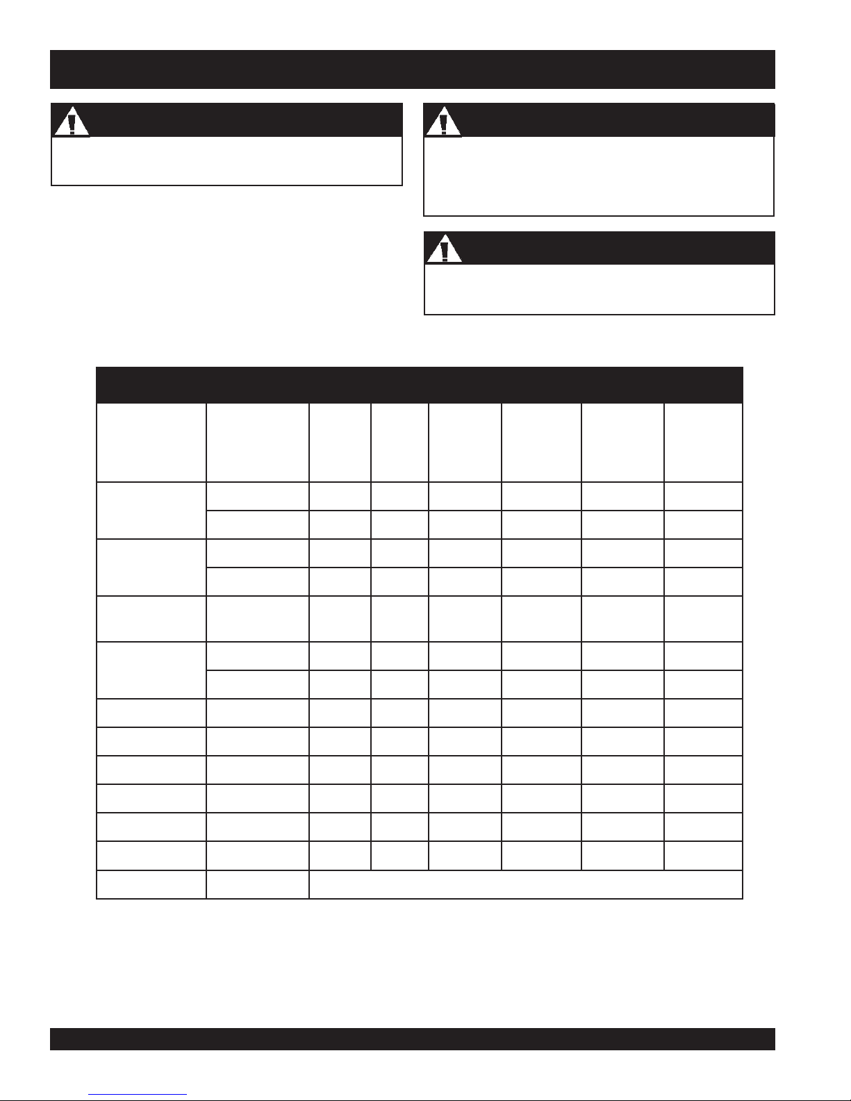
Inspection and Maintenance Service Tables.
1. To make sure your plate compactor is always in good
working condition before using, carry out the maintenance
inspection in accordance with Tables 5 through 7.
TSRIF
)3(NOITPIRCSEDNOITAREPOEROFEB
KCEHCX
liOenignE
EGNAHCX
HTNOM
RO
CAUTICAUTI
CAUTION
CAUTICAUTI
Inspection Intervals
These inspection intervals are for operation under normal
conditions. Adjust your inspection intervals based on the
number hours plate compactor is in use, and particular
working conditions.
CAUTICAUTI
CAUTION
CAUTICAUTI
Fuel Piping
Fuel piping and connections should be replaced every 2
years.
eludehcSecnanetniaMenignE.5elbaT
YREVE
SHTNOM3
RO
.SRH01
.SRH52
YREVE
SHTNOM6
RO
.SRH05
YREVE
RAEY
RO
.SRH0
01
YREVE
SRAEY2
RO
.SRH002
KCEHCX
renaelCriA
EGNAHC)1(X
stloB&stuNllA
gulPkrapS
sniFgnilooCKCEHCX
retserrAkrapSNAELC X
knaTleuFNAELC X
retliFleuFKCEHC X
deepSeldITSUJ
ecnaraelCevlaVTSUJDA-KCEHC )2(X
senilleuFKCEHC )2()yrassecenfiecalper(sraey2yrevE
l
neuqerferomecivreS)1( YTSUD .saera
fInethgit-eR
yrasseceN
NAELC-KCEHCX
ECALPER X
DA-KCEHC )2(X
vresebdluohssmetiesehT)2(
X
nidesunehwylt
yllacinahcemeradnaslootreporpehtevahuoysselnu,relaedecivresruoyybdeci
.serudecorpecivresroflaunaMpohSADNOHehtotrefeR.tneiciforp
PAGE 20 — MVC-80VH/VHW PLATE COMPACTOR — OPERATION & PARTS MANUAL — REV. #0 (05/01/06)
amreporpenimretedotnoitarepofosruohgol,esulaicremmocroF)3(
.slavretniecnanetni
MVC-80VH/VHW — MAINTENANCE
NOITCEPSNIENIHCAM.6ELBAT
metI noitarepOfosruoH
)kcehcgnitratS( )yadyreve(sruoh8yrevE
swercstsolroesooL )yadyreve(sruoh8yrevE
trapynafoegamaD )yadyreve(sruoh8yrevE
gnillortnocfonoitcnuF
trapmetsys
kcehcliorotarbiV sruoh001yrevE
liorotarbiV
tnemecalper
kcehc)hctulc(tleb-V ruoh002yrevE
yrevE
sruoh003
Daily Service
■
Check for leakage of fuel or oil.
■
Check engine oil.
■
Check for loose screws including tightness. See Table 6
below (tightening torque ), for retightening.
.7ELBAT
mm6 mm8 mm01 mm21 mm41 mm61 mm81 mm02
lairetaM
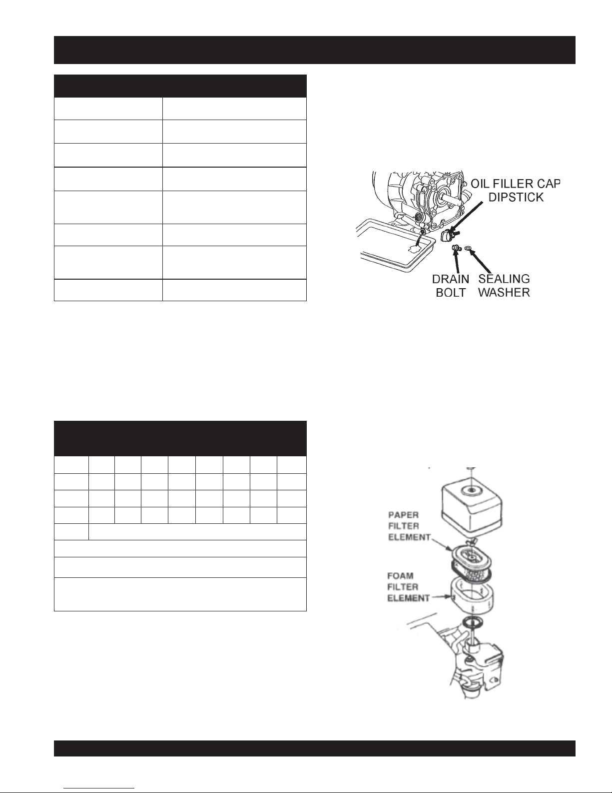
3. Replace engine oil with recommended type oil as listed
in Table 4. For engine oil capacity, see Table 2 (engine
specifications). DO NOT overfill.
4. Reinstall drain bolt with sealing washer and tighten securely.
)yadyreve(sruoh8yrevE
Figure 14. Engine Oil (Draining)
Air Filter
1. The air filter element should be cleaned because a clogged
air cleaner can cause poor engine starting, lack of power
and shorten engine life substantially.
2. To clean or replace air filter loosen the wing nut on the air
filter housing (Figure 15), remove the cover and take out air
filter cartridge. If only cleaning of the air filter is desired blow
retemaiD)mc/gk.ni(EUQROTGNINETHGIT
through the air filter cartridge from the inside, moving a jet of
dry compressed air up and down until all dust is removed.
T4 07 051 003 005 057 001,1 004,1 000,2
T8-6 001 052 005 008 003,1 000,2 007,2 008,3
T11 051 004 008 002,1 000,2 009,2 002,4 006,5
* )mm01(007~056)mm8(053~003)mm6(001
)munimulafositrap-retnuocesacnI(*
)dednahthgirllaeraenihcamsihthtiwesunisdaerhT(
,tlobhcaenodekramsilairetamfoytilauqdnalairetaM
.wercsdna
ENGINE OIL
1. Replace the engine oil in first 20 hours of operation and
every 100 hours afterwards.
warm
2. Drain the engine oil when the oil is
after operation.
Remove the oil filler cap then unscrew the engine oil drain
plug located at the base of the engine. Drain the old oil into
a pan (Figure 14).
Figure 15. Air Cleaner
MVC-80VH/VHW PLATE COMPACTOR — OPERATION & PARTS MANUAL — REV. #0 (05/01/06) — PAGE 21
 Loading...