

MQ Multiquip Mikasa MRH800DS, Mikasa Parts Manual

OPERATION AND PARTS MANUAL
SERIES
MODEL MRH800DS
VIBRATION ROLLER
(
YANMAR L100EE-DEVMK2 ENGINE
Revision #4 (11/07/18)
To find the latest revision of this
publication, visit our website at:
www.multiquip.com
)
PROPOSITION 65 WARNING
Diesel engine exhaust and some of
PAGE 2 — MRH800DS ROLLER — OPERATION AND PARTS MANUAL — REV. #4 (11/07/18)

TABLE OF CONTENTS
MRH800DS VIBRATION
ROLLER
Proposition 65 Warning ............................................. 2
Here's How To Get Help ............................................ 3
Table Of Contents ..................................................... 4
Parts Orderirocedures .............................................. 5
Safety Message Alert Symbols .............................. 6-7
Rules for Safe Operation ........................................ 8-9
Operation and Safety Decals ............................. 10-11
Roller Specifications ................................................ 12
Engine Specifications .............................................. 13
Dimensions ............................................................. 14
Features .................................................................. 15
Vibration roller Components ..............................16-17
Handle Bar/Lever Components .......................... 18-19
Engine Components ............................................... 20
Inspection ........................................................... 22-23
Initial Startup ...................................................... 24-25
Operation ........................................................... 26-27
Maintenance ...................................................... 28-33
Roller Troubleshooting ....................................... 34-35
Engine Troubleshooting ...................................... 36-37
Yanmar L100EE-DEVMK2 Engine
Cylinder Block Assembly .................................... 72-73
Cylinder Head and Cover Assembly .................. 74-75
Muffler Assembly ............................................... 76-77
Air Cleaner Assembly......................................... 78-79
Crankshaft, Piston and Camshaft Assembly ..... 80-81
Lub. Oil Pump and Governor Assembly ............. 82-83
Cooling and Starting Device Assembly .............. 84-85
Fuel Injection PumpAssembly ............................ 86-87
Fuel Tank and Fuel Line Assembly .................... 88-89
Starting Motor and Dynamo Assembly .............. 90-91
Tool Label and Gasket Set Assembly ................ 92-93
Terms and Conditions of Sale ................................. 94
NOTICE
Specification and part number are subject to
change without notice.
COMPONENT DRACOMPONENT DRA
COMPONENT DRA
COMPONENT DRACOMPONENT DRA
Explanation Of Code In Remarks Column .............. 38
Suggested Spare Parts ........................................... 39
Decal Placement ................................................ 40-41
Axle Assembly .................................................... 42-43
Base Assembly .................................................. 44-45
Front Guard Assembly ....................................... 46-47
Side Cover Assembly ......................................... 48-49
Water Tank Assembly ......................................... 50-51
Hydraulic System Assembly ............................... 52-55
Hydraulic Oil Tank Assembly .............................. 56-57
Engine Assembly ............................................... 58-59
Electric Device Assembly ................................... 60-61
Clutch (Vibration) Assembly .............................. 62-63
Vibrator Assembly .............................................. 64-65
Upper Control Arm Assembly ............................ 66-69
Lower Control Arm Assembly ............................ 70-71
WINGSWINGS
WINGS
WINGSWINGS
MRH800DS ROLLER — OPERATION AND PARTS MANUAL — REV. #4 (11/07/18) — PAGE 3

PARTS ORDERING PROCEDURES
Ordering parts has never been easier!
Choose from three easy options:
January 1
Effective:
st
, 2006
Best Deal!
Order via Internet (Dealers Only):
Order parts on-line using Multiquip’s SmartEquip website!
■ View Parts Diagrams
■ Order Parts
■ Print Specification Information
Goto www.multiquip.com and click on
Order Parts
Order via Fax (Dealers Only):
All customers are welcome to order parts via Fax.
Domestic (US) Customers dial:
1-800-6-PARTS-7 (800-672-7877)
Non-Dealer Customers:
Contact your local Multiquip Dealer for
parts or call 800-427-1244 for help in
locating a dealer near you.
to log in and save!
Order via Phone:
If you have an MQ Account, to obtain a Username
and Password, E-mail us at: parts@multiquip.
com.
To obtain an MQ Account, contact your
District Sales Manager for more information.
Use the internet and qualify for a 5% Discount
on Standard orders for all orders which include
complete part numbers.*
Note: Discounts Are Subject To Change
Fax your order in and qualify for a 2% Discount
on Standard orders for all orders which include
complete part numbers.*
Note: Discounts Are Subject To Change
Domestic (US) Dealers Call:
1-800-427-1244
International Customers should contact
their local Multiquip Representatives for
Parts Ordering information.
When ordering parts, please supply:
❒ Dealer Account Number
❒ Dealer Name and Address
❒ Shipping Address (if different than billing address)
❒ Return Fax Number
❒ Applicable Model Number
❒ Quantity, Part Number and Description of Each Part
NOTICE
All orders are treated as Standard Orders and will
ship the same day if received prior to 3PM PST.
❒ Specify Preferred Method of Shipment:
✓ UPS/Fed Ex ✓ DHL
■ Priority One ✓ Tr u ck
■ Ground
■ Next Day
■ Second/Third Day
www.multiquip.com
WE ACCEPT ALL MAJOR CREDIT CARDS!
PAGE 4 — MRH800DS ROLLER — OPERATION AND PARTS MANUAL — REV. #4 (11/07/18)

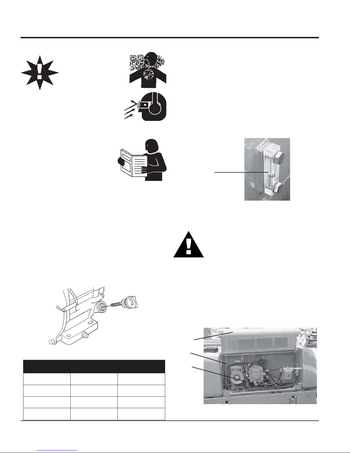
SAFETY INFORMATION
Do not operate or service the equipment before reading
the entire manual. Safety precautions should be followed
at all times when operating this equipment.
Failure to read and understand the safety
messages and operating instructions could
result in injury to yourself and others.
SAFETY MESSAGES
The four safety messages shown below will inform you
about potential hazards that could injure you or others. The
safety messages specifi cally address the level of exposure
to the operator and are preceded by one of four words:
DANGER, WARNING, CAUTION
SAFETY SYMBOLS
The following table shows the potential hazards associated
with the operation of this equipment.
Symbol Safety Hazard
or NOTICE.
DANGER
Indicates a hazardous situation which, if not avoided,
WILL result in DEATH or SERIOUS INJURY.
WARNING
Indicates a hazardous situation which, if not avoided,
COULD result in DEATH or SERIOUS INJURY.
CAUTION
Indicates a hazardous situation which, if not avoided,
COULD result in MINOR or MODERATE INJURY.
Lethal exhaust gas hazards
Explosive fuel hazards
Burn hazards
Respiratory hazards
Rotating parts hazards
NOTICE
Pressurized fluid hazards
Addresses practices not related to personal injury.
Electric shock hazards
Runover hazards
MRH800DS VIBRATORY ROLLER • OPERATION AND PARTS MANUAL — REV. #4 (11/07/18) — PAGE 5

GENERAL SAFETY
NOTICE
This equipment should only be operated by trained and
Whenever necessary, replace nameplate, operation and
Manufacturer does not assume responsibility for any
accident due to equipment modifi cations. Unauthorized
use accessories or attachments that are not
recommended by Multiquip for this equipment. Damage
keep
Also, know the phone numbers
fi re department.
This information will be invaluable in the case of an
SAFETY INFORMATION
CAUTION
NEVER operate this equipment without proper protective
clothing, shatterproof glasses, respiratory protection,
hearing protection, steel-toed boots and other protective
devices required by the job or city and state regulations.
NEVER operate this equipment when not
feeling well due to fatigue, illness or when
under medication.
NEVER operate this equipment under the infl uence of
drugs or alcohol.
ALWAYS check the equipment for loosened threads or
bolts before starting.
DO NOT use the equipment for any purpose other than
its intended purposes or applications.
ALWAYS clear the work area of any debris, tools, etc.
that would constitute a hazard while the equipment is
in operation.
qualifi ed personnel 18 years of age and older.
safety decals when they become diffi cult read.
equipment modifi cation will void all warranties.
NEVER
to the equipment and/or injury to user may result.
ALWAYS know the location of the nearest
fi re extinguisher.
ALWAYS know the location of the nearest
fi rst aid kit.
ALWAYS know the location of the nearest phone or
a phone on the job site.
of the nearest ambulance, doctor and
emergency.
PAGE 6 — MRH800DS VIBRATORY ROLLER • OPERATION AND PARTS MANUAL — REV. #4 (11/07/18)

SAFETY INFORMATION
ROLLER SAFETY
DO NOT use worn-out hoses or couplings. Inspect daily.
store equipment properly when it is not being
used. Equipment should be stored in a clean, dry location
out of the reach of children and unauthorized personnel.
The engine fuel exhaust gases contain poisonous carbon
monoxide. This gas is colorless and odorless, and can
The engine of this equipment requires an adequate
operate this equipment
place hands or fingers inside engine
operate the engine with heat shields or
while the engine is hot. Hot oil will gush out of the oil
tank and severely scald any persons in the general area
Always turn the engine off before performing maintenance.
DANGER
NEVER operate the equipment in an explosive
atmosphere or near combustible materials. An
explosion or fi re could result causing severe
bodily harm or even death.
WARNING
NEVER disconnect any emergency or safety devices.
These devices are intended for operator safety.
Disconnection of these devices can cause severe injury,
bodily harm or even death. Disconnection of any of these
devices will void all warranties.
CAUTION
NEVER lubricate components or attempt service on a
running machine.
Never leave the roller unattended with the engine
running. Turn off engine.
Use chock blocks when parking roller on a grade.
Use extreme care when operating near obstructions, on
slippery surfaces, grades, and slide slopes.
ALWAYS
ENGINE SAFETY
DANGER
cause death if inhaled.
free fl ow of cooling air. NEVER
in any enclosed or narrow
area where free fl ow of the
air is restricted. If the air
fl ow is restricted it will cause
injury to people and property
and serious damage to the
equipment or engine.
WARNING
DO NOT
compartment when engine is running.
DANGEROUS
GAS FUMES
When reversing, particularly on the edges and banks
of ditches, as well as in front of obstaces, the operator
must stay in a standing position at a safe distance from
the machine.
When operating near any house/building or pipelines,
always check the effect of machine vibration. Stop work
if necessary.
DO NOT operate the roller with the covers open.
ALWAYS keep the machine away from other personnel
and obstacles. Always keep immediate are free of
bystanders.
NOTICE
ALWAYS keep the machine in proper running condition.
Fix damage to machine and replace any broken parts
immediately.
NEVER
guards removed.
Keep fi ngers, hands hair and clothing away
from all moving parts to prevent injury.
DO NOT remove the engine oil drain plug
of the roller.
CAUTION
NEVER touch the hot exhaust manifold,
muffl er or cylinder. Allow these parts to cool
before servicing equipment.
MRH800DS VIBRATORY ROLLER • OPERATION AND PARTS MANUAL — REV. #4 (11/07/18) — PAGE 7
SAFETY INFORMATION
NOTICE
DO NOT overfi ll tank, since spilled fuel could ignite if it
comes into contact with hot engine parts or sparks from
Store fuel in appropriate containers, in well-ventilated
drop the battery. There is a possibility that the
keep the battery charged. If the battery is not
charge battery if frozen. Battery can explode.
When frozen, warm the battery to at least 61°F (16°C).
recharge the battery in a well-ventilated
environment to avoid the risk of a dangerous concentration
NEVER run engine without an air fi lter or with a dirty air
NEVER tamper with the factory settings
NEVER tip the engine to extreme angles during lifting as
FUEL SAFETY
DO NOT add fuel to equipment if it is placed inside truck
fi lter. Severe engine damage may occur. Service air fi lter
frequently to prevent engine malfunction.
of the engine or engine governor. Damage
to the engine or equipment can result
if operating in speed ranges above the
maximum allowable.
it may cause oil to gravitate into the cylinder head, making
the engine start diffi cult.
DANGER
bed with plastic liner. Possibility exists of explosion or
fi re due to static electricity.
FUEL
the ignition system.
areas and away from sparks and fl ames.
NEVER use fuel as a cleaning agent.
DO NOT smoke around or near the
equipment. Fire or explosion could result
from fuel vapors or if fuel is spilled on a
hot engine.
BATTERY SAFETY (ELECTRIC START ONLY)
DANGER
DO NOT
battery will explode.
DO NOT expose the battery to open fl ames,
sparks, cigarettes, etc. The battery contains
combustible gases and liquids. If these
gases and liquids come into contact with a
fl ame or spark, an explosion could occur.
WARNING
FUEL
DO NOT start the engine near spilled fuel or combustible
fl uids. Diesel fuel is extremely fl ammable and its vapors
can cause an explosion if ignited.
ALWAYS refuel in a well-ventilated area, away from
sparks and open fl ames.
ALWAYS use extreme caution when working with
fl ammable liquids.
DO NOT fi ll the fuel tank while the engine is running
or hot.
ALWAYS wear safety glasses when
handling the battery to avoid eye irritation.
The battery contains acids that can cause
injury to the eyes and skin.
Use well-insulated gloves when picking up
the battery.
ALWAYS
charged, combustible gas will build up.
DO NOT
ALWAYS
of combustible gases.
If the battery liquid (dilute sulfuric acid)
comes into contact with clothing or skin,
rinse skin or clothing immediately with
plenty of water.
PAGE 8 — MRH800DS VIBRATORY ROLLER • OPERATION AND PARTS MANUAL — REV. #4 (11/07/18)

If the battery liquid (dilute sulfuric acid) comes into
contact with eyes, rinse eyes immediately with plenty
TRANSPORTING SAFETY
ENVIRONMENTAL SAFETY
use food or plastic containers to dispose of
pour waste, oil or fuel directly onto the ground,
of water and contact the nearest doctor or hospital to
seek medical attention.
CAUTION
ALWAYS disconnect the NEGATIVE battery terminal
before performing service on the equipment.
ALWAYS keep battery cables in good working condition.
Repair or replace all worn cables.
CAUTION
NEVER allow any person or animal to stand underneath
the equipment while lifting.
NOTICE
Before lifting, make sure that the equipment parts are not
damaged and screws are not loose or missing.
SAFETY INFORMATION
NOTICE
Dispose of hazardous waste properly.
Examples of potentially hazardous waste
are used motor oil, fuel and fuel fi lters.
DO NOT
hazardous waste.
DO NOT
down a drain or into any water source.
Use lifting equipment capable of lifting the weight of
the roller.
Always make sure crane or lifi tng device has been
properly secured to the lifting bail (hook) of the
equipment.
ALWAYS shutdown engine before transporting.
NEVER lift the equipment while the engine is running.
Tighten fuel tank cap securely and close fuel cock to
prevent fuel from spilling.
Use adequate lifting cable (wire or rope) of suffi cient
strength.
Use one point suspension hook and lift straight upwards
with suffi cient bearing capacity to prevent machine from
tilting or slipping.
DO NOT lift machine to unnecessary heights.
ALWAYS make sure that roller is secured correctly when
transporting on a trailer. Make sure all supports attaching
the roller to the trailer are tight.
MRH800DS VIBRATORY ROLLER • OPERATION AND PARTS MANUAL — REV. #4 (11/07/18) — PAGE 9

OPERATION AND SAFETY DECALS
Figure 1 displays the operation and safety decals as they appear on the vibration roller. Should any of these decals become
damaged or unreadable, contact the Multiquip Parts Department for a replacement set.
Figure 1. Operation and Safety Decals
PAGE 10 — MRH800DS ROLLER — OPERATION AND PARTS MANUAL — REV. #4 (11/07/18)

OPERATION AND SAFETY DECALS
Figure 1. Operation and Safety Decals (Continued)
MRH800DS ROLLER — OPERATION AND PARTS MANUAL — REV. #4 (11/07/18) — PAGE 11

5"#-&.3)%47*#3"5*0/30--&341&$*'*$"5*0/4
'LPHQVLRQV
'LPHQVLRQV
%SVN%JBNFUFS JONN
%SVN8JEUI JONN
$VSC$MFBSBODF JONN
4JEF0WFSIBOH JONN
0QFSBUJOH8FJHIUXJUIXBUFS MCTLH
7JCSBUJPO'SFRVFODZ WQN
$FOUSJGVHBM'PSDF LOLHG
%SJWF4ZTUFN )ZESBVMJD.PUPS
7JCSBUJPO4ZTUFN 'SBNF
YYJOYYNN
SPECIFICATIONS
7JCSBUJPO.FUIPE #FMU%SJWF
7JCSBUPS4IBGU 5XJO
(SBEFBCMJMJUZ ¡
8PSLJOH4QFFE NQILQI
'VFM5BOL$BQBDJUZ HBMMPOTMJUFST
-VCSJDBUJOH0JM HBMMPOTMJUFST
8BUFS5BOL$BQBDJUZ HBMMPOTMJUFST
&OHJOF.PEFM :"/."3.PEFM-&&%&7.,
4UBSUJOH4ZTUFN &MFDUSJD3FDPJM4UBSU
PAGE 12 — MRH800DS ROLLER — OPERATION AND PARTS MANUAL — REV. #4 (11/07/18)

.2elbaTENIGNE)RAMNAY(SNOITACIFICEPS
ledoMenignE 1KMVED-EE001LRAMNAY
epyTenignEleseiDdelooc-riA
ekortSXeroBrednilyC )mm07x88(ni57.2x64.3
SPECIFICATIONS
lpsiD)cc604(zolf7.31
tnemeca
tupuOmumixaMPH01
yticapaCknaTleuF)sretil5.5(strauq8.5
yticapaCliO )sretil56.1(strauq47.
thgieWteNyrD)gk35(.sbl6.611
)HxWxL(snoisnemiD )mm494x074x714(ni4.91x5.81x4.61
1
MRH800DS ROLLER — OPERATION AND PARTS MANUAL — REV. #4 (11/07/18) — PAGE 13

DIMENSIONS
SNOISNEMID.3ELBAT
A.ni501.mm0762
B.ni75.mm5441
HTGNEL
HTDIW
THGIEH
C.ni01.mm552
D.ni8.22.mm085
E.ni8.31.mm053
F.ni2.72.mm296
G.ni6
H.ni3.87.mm0991
I.ni5.64.mm0811
J.ni4.73.mm059
K.ni7.14.mm0601
L.ni6.9.mm542
.31.mm643
Figure 2. MRH-800DS Vibration Roller Dimensions
PAGE 14 — MRH800DS ROLLER — OPERATION AND PARTS MANUAL — REV. #4 (11/07/18)

The Mikasa Model MRH-800DS is a powerful compacting
tool capable of applying a tremendous force in consecutive
impacts to a soil surface. Its applications include soil compacting
for backfilling for gas pipelines, water pipelines and cable
installation work.
The impact force of the MRH-800DS levels and uniformly
compacts voids between soil particles to increase dry density.
Features include:
Hydraulic transmission to allow speed change without
gear shifting.
Deadman device which when pressed or hit will
cause the travel lever to return to neutral position
bringing the machine to a stop.
A horn to warn of machine’s approach.
Non-corrosive water tank for the sprinkler system with a
capacity of more than 10 gallons.
Lifting hook to transport machine.
Front bumper and working light.
GENERAL INFORMATION
Narrow profile with less than one inch wall clearance.
Narrower width allows access to tighter areas. No
exposed hydraulic hoses.
Oil bath lubricated bearings and external vibration
for less servicing and more dependability.
Front and rear drum scrapers.
Drum sprinkler system controls located near the
operator.
Easy access to hydraulic components and hydraulic
filter.
MRH800DS ROLLER — OPERATION AND PARTS MANUAL — REV. #4 (11/07/18) — PAGE 15
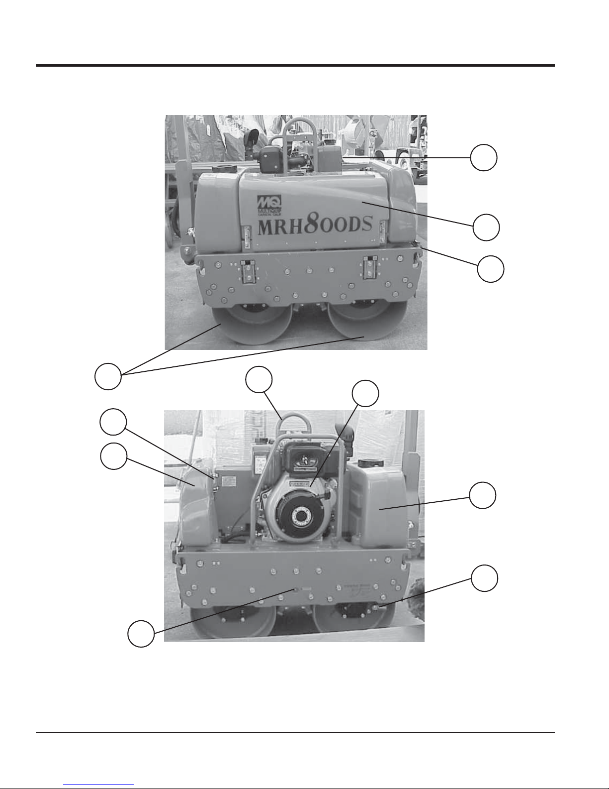
COMPONENTS
1
2
4
3
8
9
5
6
10
11
7
PAGE 16 — MRH800DS ROLLER — OPERATION AND PARTS MANUAL — REV. #4 (11/07/18)
Figure 3. MRH-800DS Vibration Roller Components

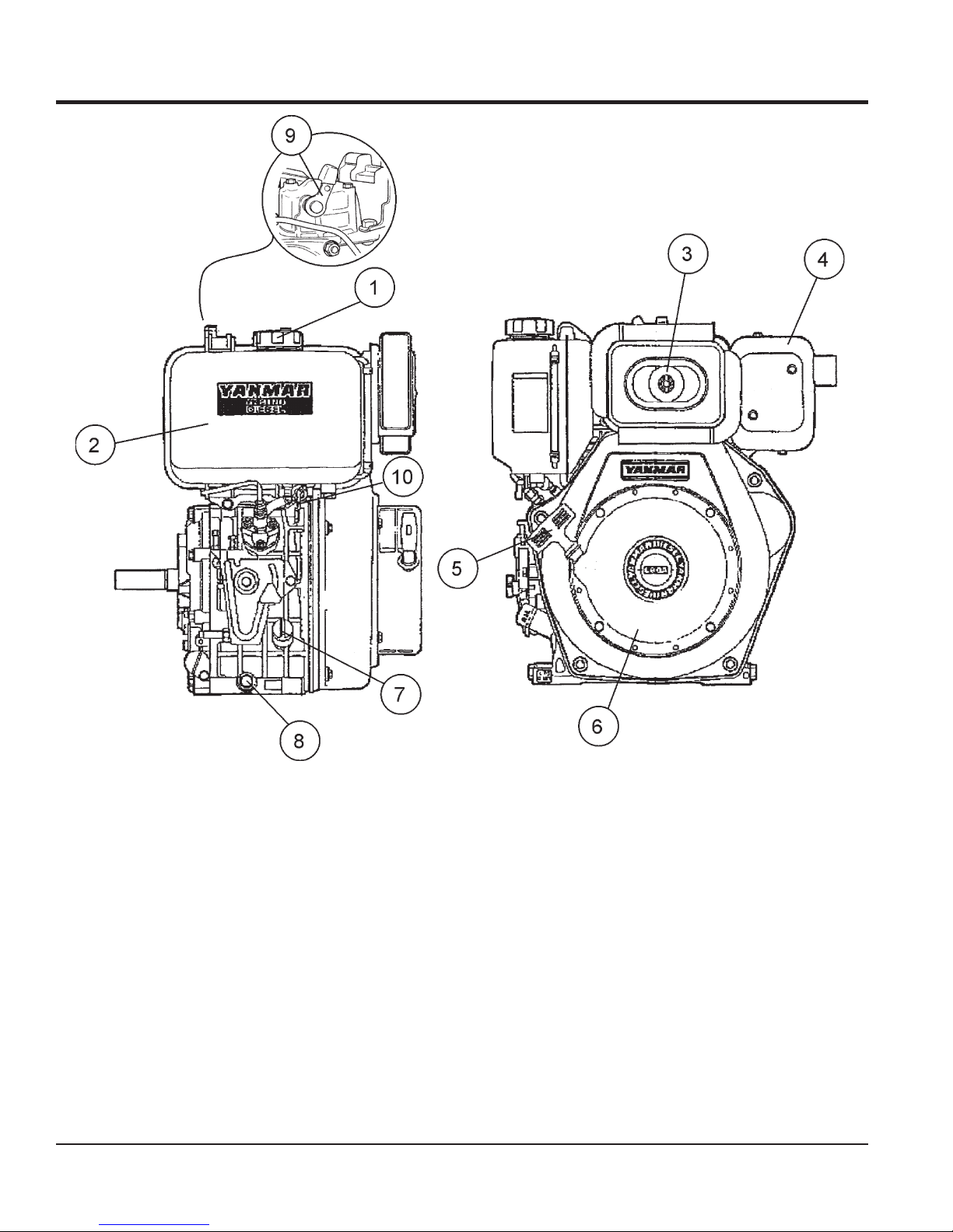
Figure 3 illustrates the location of the major components
for the MRH-800DS Vibration Roller. The function of each
component is described below:
1. Fuel Tank/Cap – Fill with diesel fuel. Fuel tank holds
approximately 2 gallons (7.5 liters). DO NOT top off fuel.
Wipe up any spilled fuel immediately.
2. Center Cover – When opened and supported by strut,
provides access to oil pump and filter, battery, V-belt, and
clutch box.
3. Vibration Rollers – 25-inch wide steel drums that provide
compaction force in the compaction and patching of asphalt
type surfaces.
4. Front Headlights – Activate using switch on control
handle. Use to illuminate ground durring nighttime or low
light operating conditions.
5. Hydraulic Oil Gauge – Indicates the hydraulic oil level.
6. Oil Tank – Fill with proper grade of hydraulic oil.
7. Vibrator Oil Level Plug – Remove to check vibrator oil
level.
COMPONENTS
8. Lifting Hook – Used to lift the machine with crane or other
lifting device.
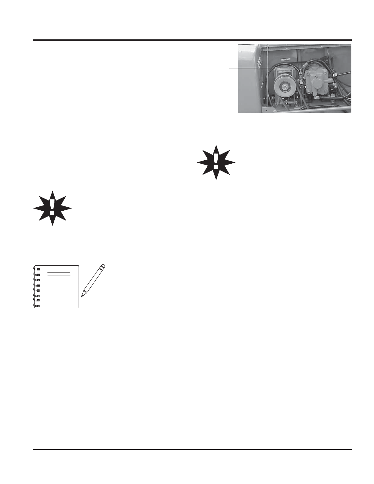
9. Engine – This machine uses the Yanmar L100A engine.
Refer to the engine Owner’s Manual for more information.
10. Water Tank– Holds 10.57 gallons (40 liters) for the sprinkler
system.
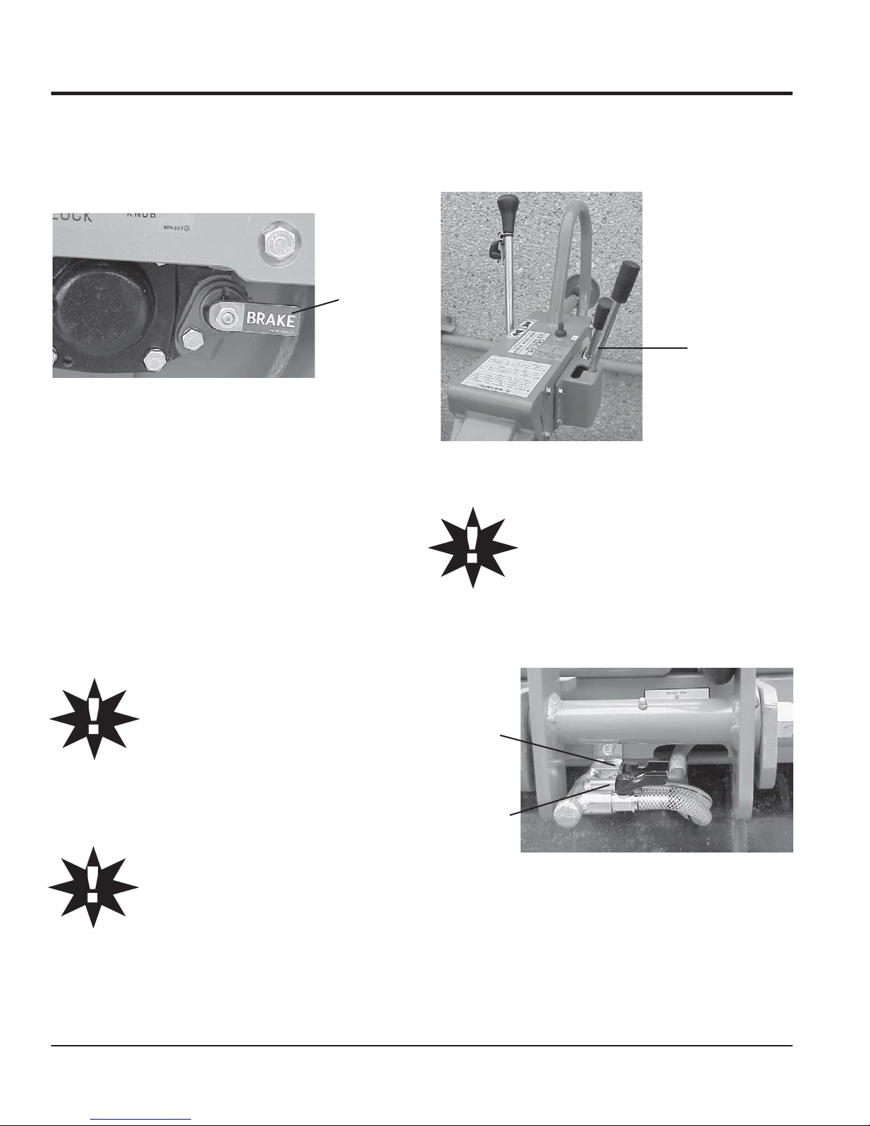
11. Parking Brake – Makes sure machine will not accidentally
move when parked or not in use.
MRH800DS ROLLER — OPERATION AND PARTS MANUAL — REV. #4 (11/07/18) — PAGE 17
3
4
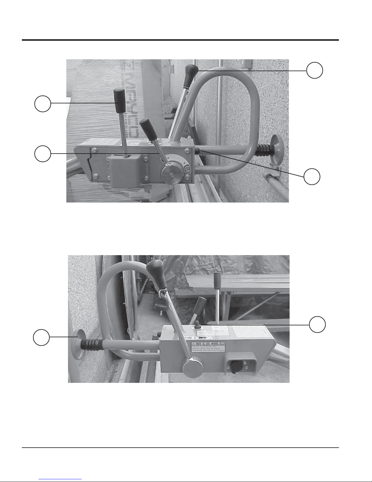
HANDLE BAR/LEVER COMPONENTS
1
2
5
PAGE 18 — MRH800DS ROLLER — OPERATION AND PARTS MANUAL — REV. #4 (11/07/18)
6
Figure 4. MRH-800DS Lever Components

HANDLE BAR/LEVER COMPONENTS
HANDLE BAR/LEVER COMPONENTS
Figure 4 illustrates the location of the major lever
components on the handle bar of the machine. Each
component is described below:
1. Travel Lever – Controls the direction of travel of the
machine (forward and reverse).
2. Horn Button – When pressed, gives a warning sound of
the machine approaching.
3. Vibration Lever – Turns vibration on and off.
4. Throttle Lever – Controls the start up of the machine.
5. Dead-Man Device – When pressed or hit while traveling
in reverse, causes the travel lever to return to neutral
position to stop the machine.
6. Light ON/OFF Switch - Turns headlight on and off.
7. Starter Switch - Engine starts when key is turned to the
RUN position
MRH800DS ROLLER — OPERATION AND PARTS MANUAL — REV. #4 (11/07/18) — PAGE 19
BASIC ENGINE
Figure 5. MVH-402DSB Engine Components
ENGINE COMPONENTS
Figure 5 illustrates the location of the major engine
components of the machine. Each component is described
below:
1. Fuel Filler Cap – Remove this cap to add unleaded
gasoline to the fuel tank. Make sure cap is tighten securely.
DO NOT over fill.
2. Fuel Tank – Diesel engine holds 5.8 quarts of diesel fuel.
3. Air Cleaner – Prevents dirt and other debris from entering
the fuel system. Remove wing-nut on top of air filter
cannister to gain access to filter element.
4. Muffler – Used to reduce noise and emissions.
5. Recoil Starter (pull rope) – Type of engine starting method.
Alternate type would be electric start (ignition key).
PAGE 20 — MRH800DS ROLLER — OPERATION AND PARTS MANUAL — REV. #4 (11/07/18)
6. Recoil Starter – Housing for pull rope and starter.
7. Oil Filler Cap/Dipstick – Remove this cap to add oil to the
oil tank. Use dipstick to check oil level.
8. Oil Drain Plug – Unscrew plug to drain oil from engine
crankcase. Dispose of oil in a safe manner.
9. Decompression Lever – Press down before starting
engine. To prevent damage to the engine, DO NOT use for
any other purpose.
10. Fuel Cock – Controls the flow of diesel fuel to the engine.
Must be in the ON position when starting and running the
engine.

NOTES
MRH800DS ROLLER — OPERATION AND PARTS MANUAL — REV. #4 (11/07/18) — PAGE 21
INSPECTION
DANGER
NEVER operate the
compactorin a confined
area or enclosed area
structure that does not
provide ample
.
of air
ALWAYS wear approved eye and hearing
protection before operating the compactor.
Before Starting
1. Read safety instructions at the
beginning of manual.
2. Remove dirt and dust, particularly
in theengine cooling air inlet,
carburetor and air cleaner.
3. Check the air filter for dirt and dust.
If air filter is dirty, replace air filter
with a new one as required.
4. Check carburetor for external dirt and dust. Clean with dry
compressed air.
free flow
3. Insert and remove the dipstick without screwing it into the
filler neck. Check the oil level shown on the dipstick.
4. If the oil level is low, fill to the edge of the oil filler hole with the
recommended oil type (Table 3). Maximum oil capacity is
1.16 quarts (1.1 liters).
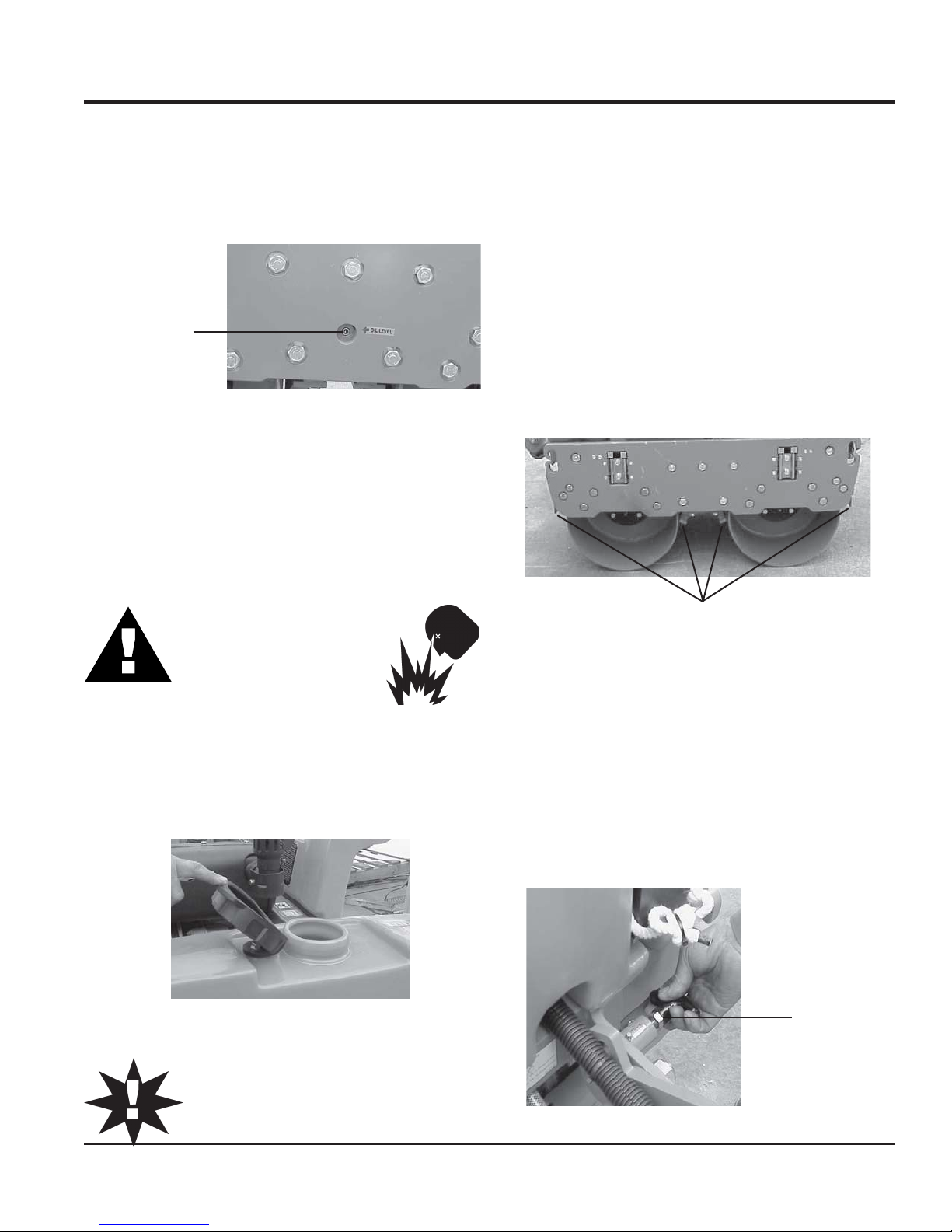
Checking The Hydraulic System
1. Check the oil tank level gauge (Figure 7). Oil level
should be at the middle indication of the gauge or
higher. Fill as required
2. Check the surroundings of the oil tank, hydraulic
pump and motor for oil leakage.
Level should
be middle of
gauge or
higher
Figure 7. Hydraulic System Oil Level Gauge
5. Check fastening nuts and bolts for tightness.
6. Understand the geographical features and regulations of
DANGER
the job site.
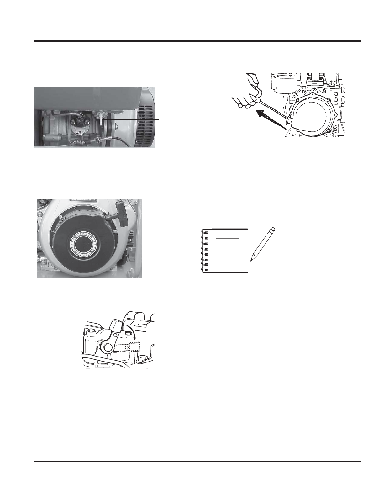
Engine Oil Check
1. To check the engine oil level, place the compactor on secure
level ground with the engine stopped.
2. Remove the filler dipstick from the engine oil filler hole
(Figure 6) and wipe clean.
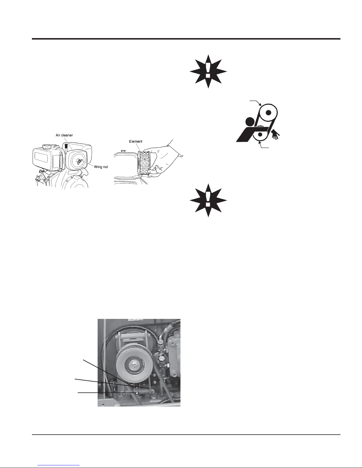
Checking The V-Belt
1. Remove the 2 bolts, one on each side of the center
cover, with a #13 socket wrench. Open the center
cover of the machine and support it with the strut by
inserting its end to the hole in the base (Figure 8).
2. Check V-belt for proper tension. Insufficient tension
causes weak vibration.
Center
Cover
Figure 6. Engine Oil Level
EPYTLIO.4ELBAT
nosaeS erutarepmeT epyTliO
Strut
V-Belt
ALWAYS keep hands and fingers away from
pinch points. DO NOT allow anyone to reach in
on dangerous sections of the machine to avoid
any accidents.
remmuS rehgiHroC°52 03-W01EAS
llaF/gnirpS C°01~C°52 02/03-W01EAS
retniW rewoLroC°0 01-W01EAS
PAGE 22 — MRH800DS ROLLER — OPERATION AND PARTS MANUAL — REV. #4 (11/07/18)
Figure 8. Checking V-Belt Tension
INSPECTION
Checking The Vibrator Oil Level
1. Check vibrator casing for any oil leakage.
2. If any leakage is noticed, remove the level plug on the side
of the plate (Figure 9).
3. Check the oil level.
Vibrator Oil
Level Plug
Figure 9. Checking Vibrator Oil Level
Fuel Check
1. Remove the fuel cap located on top of the engine fuel tank.
2. Visually inspect to see if the fuel level is low. If fuel is low,
replenish with unleaded gasoline using a strainer for
filtration. DO NOT top-off fuel. Wipe up any spilled fuel
immediately!
Checking Levers and Horn
1. Check travel, vibration, and throttle levers to make sure
they are functioning properly (Figure 4).
2. With travel lever placed in reverse, push the deadman
device and verify that the travel lever returns to neutral
position. The travel lever stays in neutral position once the
deadman device is released.
3. Press the horn and verify that it functions properly.
Checking Scrapers
1. Check scrapers and make sure that they are not clogged
with mud, bent or damaged (Figure 11).
2. Adjust clearance between drums and scrapers as
necessary.
DANGERDANGER
DANGER
DANGERDANGER
Motor fuels are highly
flammable and can be
dangerous if mishandled.
DO NOT smoke while
refueling. DO NOT attempt to refuel the pump
if the engine is
Checking Water Tank
1. Check the water tank to see if filled. Add water if necessary.
The water tank has a capacity of approximately 10 gallons
(40 liters) (Figure 10).
hot! or running
Figure 10. Checking Water Tank
.
CAUTION :
Scrapers
Figure 11. Checking Scrapers
Checking Bolts, Nuts and Screws
1. Check bolts, nuts, and screws on various parts of the
machine, including the engine, for proper tightness.
Positioning the Handle Bar
1. Release the handle bar release pin (Figure 12) and position
the handle bar to the lowered position before starting
operation.
2. When machine is not in use, release the handle bar release
pin and position the handle bar to the upright position.
Handle Bar
Release Pin
Be careful not to confuse the water tank with the
oil tank.
MRH800DS ROLLER — OPERATION AND PARTS MANUAL — REV. #4 (11/07/18) — PAGE 23
Figure 12. Positioning the Handle Bar

STARTUP
CAUTION :
DO NOT attempt to operate the roller until the Safety, General
Information and Inspection sections of this manual have been
read and thoroughly understood
This section is intended to assist the operator with the
start-up
be read carefully before attempting to use the compactor in the
field.
STARTING THE ENGINE
The engine can be started by motor (electric) or manually
(recoil). Refer to Figures 3 and 4 for the location of
controls and components.
of the roller. It is extremely important that this section
.
initial
CAUTION :
Make sure to follow all safety rules referenced in
the safety section of this manual before operating
roller. Keep work area clear of debris and other
objects that could cause damage to the roller or
bodily injury.
5. Insert the starter key into the key switch and turn it to
the RUN position (Figure 14). The buzzer should
sound at this time.
6 Turn the starter key further to the right to the START
position to start the engine. Buzzer stops sounding
when the engine speed increases. With safety switch
equipped, motor runs only when the travel lever is in
the neutral position.
Figure 14. Starter Key (Run Position)
CAUTION :
When the engine is running, NEVER turn the
starter key to the START position
Electric Start
1. On the control handle:
A. Move the
B. Move the
C. Move the
4. Open the fuel cock by turning it clockwise to the down
position (Figure 13).
throttle lever
travel lever
vibration lever
to the RUN position.
to the NEUTRAL position.
to the OFF position.
Fuel Cock
(Open
Position)
7. If the engine fails to start, DO NOT continue to rotate
the starter key for more than 5 seconds. Return the
key to the RUN position and wait 20 to 30 seconds
before starting again.
8. After starting the engine, continue to warm up the
engine for about 3 to 10 seconds especially in cold
weather.
9. If the buzzer does not stop sounding after the engine
has started, shutdown engine immediately and check
engine oil level. The buzzer functions as engine oil
level warning also.
Figure 15. Starter Key (Start Position)
Figure 13. Open Fuel Cock
PAGE 24 — MRH800DS ROLLER — OPERATION AND PARTS MANUAL — REV. #4 (11/07/18)
Recoil Start
1. Move the throttle lever to the RUN position.
2. Open the fuel cock by turning it clockwise to the down
position (Figure 16).
Fuel Cock
(Open
Position)
5. Pull the starting handle hard and fast to start engine
(Figure 19).
STARTUP
Figure 19. Engine Start Handle
Figure 16. Open Fuel Cock
3. Pull the starting handle slowly until you feel some
resistance (Figure 17). Return handle to original
position.
Pull
Handle To
Start
Figure 17. Engine Start Handle
4. Push down the decompression lever (Figure 18).
6. If the engine does not start, repeat steps
3 through 5.
NOTE
When starting with a motor
starter, a decompressor is
not normally required.
However, when ambient
temperature or battery
charger level is low, use of
a decompressor will help
make the start-up easier.
Figure 18. Decompression Lever
MRH800DS ROLLER — OPERATION AND PARTS MANUAL — REV. #4 (11/07/18) — PAGE 25
OPERATION
TRAVELING
1. Before starting to travel, make sure to release parking brake
located on the left side of the rear roller. If the parking brake
lever is tight, moving the roller back and forth will make it
easier (Figure 20).
Parking
Brake
(Released
Position)
Figure 20. Parking Brake
2. With the throttle lever in the RUN position, increase
the engine rotation.
3. Push the travel lever forward slightly. This will cause
the roller to travel forward at slow speed.
4. To increase the travel speed, push the travel lever
further.
5. Travel speed can be varied between 0 and 3 km/h
(both forward and reverse).
6. Push the travel lever backward to go in the reverse
direction.
CAUTION :
DO NOT reduce speed during work. When
shifting travel lever from forward to reverse,
be sure to stop the lever at the neutral
position first before moving the lever to the
opposite direction. DO NOT shift the lever
from forward to reverse (or reverse to
forward) in one motion.
CAUTION :
After test travel, shut down engine and
check for any problems including oil
leakage. If any trouble is found, correct the
problem before attempting to operate the
roller again.
VIBRATING
1. Shift the vibration lever AWAY from its OFF position. The
vibration lever will automatically spring forward and the
roller will start vibrating (Figure 21).
CAUTION :
WATERING
1. For watering work, turn the water cocks clockwise, at the
rear of the machine, to start sprinkling. (Figure 22).
Watercock
for Front
Drum
Watercock
for Rear
Drum
Off Position of
Vibration Lever
Figure 21. Vibration Lever
Using vibration with clutch slipping causes
the clutch to burn. Also, vibration should
NOT be used over completely compacted
area, paved road surface, or with stationary
roller.
Figure 22. Water Cocks
PAGE 26 — MRH800DS ROLLER — OPERATION AND PARTS MANUAL — REV. #4 (11/07/18)
SAFETY FEATURES
OPERATION
1. A horn is provided to warn of approach.
2. The dead man device prevents accidental traveling
in reverse. It automatically makes the travel lever
return to neutral position by stopping the machine
when an object comes in contact with the dead man
device.
STOPPING
1. With travel lever in the NEUTRAL position, and the
vibration lever in the OFF position, return the throttle
lever to the START position. Allow the machine to
cool down for 3 to 5 minutes.
2. Push the throttle lever forward to stop the engine. In
a motor start, return the key switch to the STOP
position as soon as the engine stops.
Bypass
Valve
Bolt
CAUTION :
CAUTION :
Neglecting to return the key switch to the
STOP position will cause the battery to
discharge making start up impossible the
next time.
3. After the engine stops, close the fuel cock.
4. Lock the parking brake by pulling the brake lever
and rotating it 90 degrees clockwise.
Parking brake system should
NOTE
always be kept clean to avoid
mud deposits.
LIFTING
1. Use a crane or lift to load and unload the machine. A
skilled crane operator is required to perform the job.
2. When lifting the machine, check for any damaged or
loose bolts, lifting hooks, and shock mounts.
3. Check any damaged or loose bolts in the guard frame to
avoid machine sliding off.
4. Make sure that the machine is shut off before machine is
lifted.
5. Use reliable cable for lifting.
6. ALWAYS lift the machine vertically and keep the
machine away from workers and animals.
Figure 23. Location of Bypass Valve Bolt
NEVER tow roller with any type of vehicle.
Doing so will damage the hydraulic system.
NEVER perform unloading procedure on a
slope. This may cause roller to roll down if
parking brake or blocking is deficient.
UNLOADING
1. If you need to move the roller by pushing it manually
once engine is stopped, loosen bolt of bypass valve
on oil pump by one rotation counterclockwise. This
will cause the hydraulic break to disengage and allow
the roller to be moved more easily (Figure 23).
2. After moving, tighten the bolt again. Tightening torque
is 55 to 70 kgf-cm.
MRH800DS ROLLER — OPERATION AND PARTS MANUAL — REV. #4 (11/07/18) — PAGE 27
7. DO NOT lift the machine higher than the required
height.
TRANSPORTING
1. Always make sure that the machine is shut off while
being transported.
2. Check that the fuel cap is properly closed and
tightened.
3. When traveling long distances or on rugged terrain,
drain the fuel of the machine before transporting.
4. Tie down the machine securely on the
transportation so that it will not move or topple over.

MAINTENANCE
CAUTION:
Inspection and other services should ALWAYS
be carried out on hard and level ground with the
engine shutdown.
Inspection and Maintenance Service Tables.
1. To make sure your plate compactor is always in good
working condition before using, carry out the maintenance
inspection in accordance with Tables 5 through 7.
SD008-HRM.5ELBATNOITCEPSNIENIHCAM
METI
gnissiMroesooL
swercS
straPdegamaD
gnillortnoCfonoitcnuF
traPmetsyS
FOSRUOH
NOITAREPO
sruoh8yrevE
)yadyreve(
sruoh8yrevE
)yadyreve(
sruoh8yrevE
)yadyreve(
SKRAMER
CAUTION:
Fuel piping and connections should be replaced
every 2 years.
METINOITAREPOFOSRUOH
kaeLleuFroliO)yadyreve(sruoh8yrevE
sdaerhT
tnemhsinelpeR
gnE
gninaelCretliFriAsruoh001yrevE
nigneetarapeseeS
SD008-HRM.6ELBATKCEHCENIGNE
gninetsaFfossenthgiT
nakcehCliOenignE
d
)level
tnemecalpeRliOeni
sruoh001
)yadyreve(sruoh8yrevE
)yadyreve(sruoh8yrevE
mumixamdeificepsothsinelpeR(
ot05yrevenehtsruoh52tsrifretfA
.kcehcenignenosliatedroflauname
kaeLmetsySciluardyHsruoh001yrevE72egapeeS
tarbiVsruoh001yrevE72egapeeS
kcehCliOro
liOrotarbiV
tnemecalpeR
kcehCliOciluardyHsruoh001yrevE62eg
liOciluardyH
tnemecalpeR
kcehC)hctulc(tleb-Vsruoh002
kcehCyrettaBsruoh001yrevE82egapeeS
yrevE72egapeeS
CAUTION:
These inspection intervals are for operation
under normal conditions. Adjust your inspection
intervals based on the number of hours the roller
is in use, and your particular working conditions.
sruoh003yrevE62egapeeS
002retfatsriF
yreveneht,sruoh
sruoh000,1
Daily Service
Check for leakage of fuel or oil.
Check for loose screws including tightness. See Table 7
below (tightening torque ), for retightening:
apeeS
mm6 mm8 mm01 mm21 mm41 mm61 mm81 mm02
lairetaM
72egapeeS
T4 07 051 003 005 057 001,1 004,1 000,2
T8-6 001 052 005 008 003,1 000,2 007,2 008,3
T11 051 004 008 002,1 000,2 009,2 002,4 006,5
~003
* 001
Remove soil and clean the bottom of compaction plate.
Check hydraulic pump, piping and hose for any leakage.
~056
053
007
)munimulafositrap-retnuocesacnI(*
kramsilairetamfoytilauqdnalairetaM
)mc/gk.ni(EUQROTGNINETHGIT.7ELBATRETEMAID
)dednahthgirllaeraenihcamsihthtiwesunisdaerhT(
.wercsdna,tlobhcaenode
A loosened hydraulic hose can be a cause for leakage.
Check hydraulic hose connections with wrench applied for
tightness.
PAGE 28 — MRH800DS ROLLER — OPERATION AND PARTS MANUAL — REV. #4 (11/07/18)
Check engine oil.
MAINTENANCE
Engine Oil Replacement:
1. Replace engine oil in the first 25 hours of operation and
every 50 to 100 hours afterwards.
2. Oil may be drained more easily when it is warm after
operation (For more details, see separate engine Owner's
Manual).
Air Filter
1. The air filter element should be cleaned because a clogged
air cleaner can cause poor engine starting, lack of power
and shorten engine life substantially.
CAUTION:
CAUTION :
Figure 24. Engine Air Filter and Element
2. To clean or replace air filter loosen the wing nut on the air
filter housing (Figure 24) remove the cover and take out air
filter cartridge. If only cleaning of the air filter is desired blow
through the air filter cartridge from the inside, moving a jet of
dry compressed air up and down until all dust is removed.
VIBRATION CLUTCH ADJUSTMENT
1. Move vibration lever to the OFF position.
2. Loosen the front and rear nuts at the end of vibration clutch
cable (Figure 25).
3. Turn in the nut on the front side again and at the position
that release fork starts to move, turn in the nut by one or two
threads. Lock it a this position together with the rear nut.
HYDRAULIC SYSTEM INSPECTION AND SERVICE
1. Check motor and pump for any damage.
2. Check hoses and pipes for proper tightness and make sure
there are no leaks.
3. Check nylon tubes for hydraulic oil intake and drain.
Retighten brass nut if loose and if a leak is detected. If leak
continues after retightening, replace nylon tube, nut and
sleeve.
NEVER attempt to check the V-belt with the engine running. Severe injury can occur if your hand
gets caught between the V-belt and the clutch
(Figure 26). Always use safety gloves.
CLUTCH
PULLEY
VIBRATOR
PULLEY
Figure 26. V-Belt Hazard
Excessive turning of front nut may cause the
sliding engagement of clutch to take place or
no vibration takes place even when vibration
lever is engaged.
On the other hand, insufficient turn may cause
sliding engagement of clutch even when the
vibration lever is placed in the OFF position or
for vibration to remain engaged.
Rear Nut
Fork
Front Nut
Figure 25. Vibration Clutch Adjustment
MRH800DS ROLLER — OPERATION AND PARTS MANUAL — REV. #4 (11/07/18) — PAGE 29
4. Check oil tank for proper oil level using the hydraulic system
oil level gauge (See Figure 7). Make sure hydraulic oil has
not whitened or emulsified. Whitish color means aeration in
pump. Retighten pipe and correct level of oil. Emulsification
means water in the hydraulic oil. Replace the oil.
ROLLER INSPECTION AND ADJUSTMENT
1. Refer to Table 8 for oil and grease requirements.
2. Check oil tank level daily.
3. Check the machine for oil leak and proper function of lever,
cables, and links daily.
 Loading...