

MQ Mqs36h55, Mqs36h90h Parts Manual

OPERATION AND PARTS MANUAL
MODEL MQS36H55
MODEL MQS36H90H
WALK-BEHIND TROWEL
(HONDA GX160UT1QX2/GX270UTQA2
GASOLINE ENGINES)
Revision #0 (03/08/12)
To find the latest revision of this
publication, visit our website at:
www.multiquip.com
THIS MANUAL MUST ACCOMPANY THE EQUIPMENT AT ALL TIMES.
PN: 22902

FUEL AND CHEMICAL EXPOSURE WARNINGS
Gasoline engine exhaust and some of
its constituents, and some dust created
by power sanding, sawing, grinding,
drillingandotherconstructionactivities
contains chemicals known to the State
of California to cause cancer, birth
defects and other reproductive harm.
Some examples of these chemicals are:
Leadfromlead-basedpaints.
Crystallinesilicafrombricks.
Cementandothermasonryproducts.
Arsenicandchromiumfrom chemically
treatedlumber.
Your risk from these exposures varies,
dependingonhowoftenyoudothistype
of work. To reduce your exposure to
these chemicals: work in aALWAYS
well ventilated area, and work with
approved safety equipment, such as
dust masks that are specially designed
to filter out microscopic particles.
PAGE 2 — MQS36H SERIES WALK-BEHIND TROWEL • OPERATION AND PARTS MANUAL — REV. #0 (03/08/12)
SILICOSIS/RESPIRATORY WARNINGS
WARNING
SILICOSIS WARNING RESPIRATORY HAZARDS
Grinding/cutting/drilling of masonry, concrete, metal and
other materials with silica in their composition may give
off dust or mists containing crystalline silica. Silica is a
basic component of sand, quartz, brick clay, granite and
numerous other minerals and rocks. Repeated and/or
substantial inhalation of airborne crystalline silica can
cause serious or fatal respiratory diseases, including
silicosis. In addition, California and some other
authorities have listed respirable crystalline silica as a
substance known to cause cancer. When cutting such
materials, always follow the respiratory precautions
mentioned above.
WARNING
Grinding/cutting/drilling of masonry, concrete, metal and
other materials can generate dust, mists and fumes
containing chemicals known to cause serious or fatal
injury or illness, such as respiratory disease, cancer,
birth defects or other reproductive harm. If you are
unfamiliar with the risks associated with the particular
process and/or material being cut or the composition of
the tool being used, review the material safety data
sheet and/or consult your employer, the material
manufacturer/supplier, governmental agencies such as
OSHA and NIOSH and other sources on hazardous
materials. California and some other authorities, for
instance, have published lists of substances known to
cause cancer, reproductive toxicity, or other harmful
effects.
Control dust, mist and fumes at the source where
possible. In this regard use good work practices and
follow the recommendations of the manufacturers or
suppliers, OSHA/NIOSH, and occupational and trade
associations. Water should be used for dust
suppression when wet cutting is feasible. When the
hazards from inhalation of dust, mists and fumes cannot
be eliminated, the operator and any bystanders should
always wear a respirator approved by NIOSH/MSHA for
the materials being used.
MQS36H SERIES WALK-BEHIND TROWEL • OPERATION AND PARTS MANUAL — REV. #0 (03/08/12) — PAGE 3

TABLE OF CONTENTS
MQS36H55/MQS36H90H
WAKL-BEHIND TROWEL
Fuel and Chemical Exposure Warnings .................. 2
Silicosis/Respiratory Warnings ................................ 3
Table Of Contents .................................................... 4
Training Checklist .................................................... 5
Daily Pre-Operation Checklist ................................. 6
Safety Information ..............................................7-11
Trowel Specifications/Dimensions ......................... 12
Engine Specifications ............................................ 13
General Information ............................................... 14
Trowel Components ............................................... 15
Engine Components .............................................. 16
Assembly and Installation ................................. 17-18
Inspection ......................................................... 19-21
Operation ..........................................................21-26
Options ............................................................. 27-28
Maintenance ..................................................... 29-37
Troubleshooting ................................................38-41
Wiring Diagram ...................................................... 42
Explanation Of Code In Remarks Column............. 44
Suggested Spare Parts ......................................... 45
Component Drawings
Nameplate and Decals Assembly ..................... 46-47
Standard Handle Assembly .............................. 48-49
Quick-Pitch Handle Assembly (Option) ............ 50-51
Guard Assembly ............................................... 52-53
Gearbox Assembly. ........................................... 54-55
Engine Assembly .............................................. 56-57
Spider Assembly ............................................... 58-59
Blade Assembly ................................................ 60-61
Engine Assembly .............................................. 62-63
NOTICE
Specifications and part numbers are subject to change
without notice.
PAGE 4 — MQS36H SERIES WALK-BEHIND TROWEL • OPERATION AND PARTS MANUAL — REV. #0 (03/08/12)

TRAINING CHECKLIST
Training Checklist
No. Description OK? Date
1
2
3 Fuel system, refueling procedure.
4
5
6 Emergency stop procedures.
7 Startup of machine, engine choke.
8 Maintaining a hover.
9 Maneuvering.
10 Pitching.
11 Concrete fi nishing techniques.
12 Shutdown of machine.
Read operation manual
completely.
Machine layout, location of
components, checking of engine
oil level.
Operation of controls (machine
not running).
Safety controls, safety stop switch
operation.
13 Lifting of machine (lifting bale).
14 Machine transport and storage.
MQS36H SERIES WALK-BEHIND TROWEL • OPERATION AND PARTS MANUAL — REV. #0 (03/08/12) — PAGE 5

DAILY PRE-OPERATION CHECKLIST
Daily Pre-Operation Checklist
1 Engine oil level
2 Condition of blades
3 Blade pitch operation
4 Safety stop switch operation
PAGE 6 — MQS36H SERIES WALK-BEHIND TROWEL • OPERATION AND PARTS MANUAL — REV. #0 (03/08/12)
SAFETY INFORMATION
Do not operate or service the equipment before reading
Potential hazard associated with the operation of this
which
P/N 23700
allow any person
to stand underneath the trowel while lifting.
NEVER
P/N
360
99
ALWAYS wear protective clothing when
operating this equipment
This machine to be operated by qualified
personnel. Ask for training as needed.
Lifting Crush Hazard
lift trowel with pans attached.DO NOT
WARNING
WARNING
Read Manual
NEVER operate this equipment with guards
removed. Keep hands clear.
WARNING
Training
Guard Hazard
WARNING
make sure handle is securely attached.
On Quick Pitch™ models make sure T-Handle
latch is locked (engaged).
ALWAYS
DECAL
SAFETY HAZARD
the entire manual. Safety precautions should be followed
at all times when operating this equipment.
Failure to read and understand the safety
messages and operating instructions could
result in injury to yourself and others.
SAFETY MESSAGES
The four safety messages shown below will inform you
about potential hazards that could injure you or others. The
safety messages specifi cally address the level of exposure
to the operator and are preceded by one of four words:
DANGER, WARNING, CAUTION or NOTICE.
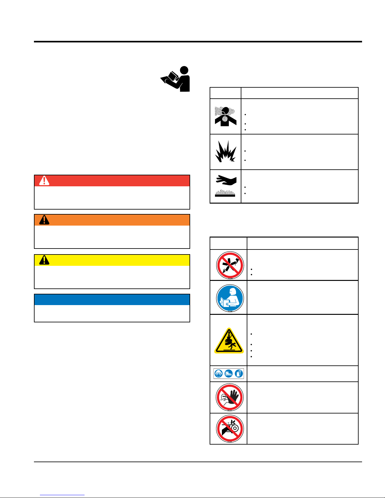
SAFETY SYMBOLS
DANGER
Indicates a hazardous situation which, if not avoided,
WILL result in DEATH or SERIOUS INJURY.
WARNING
Indicates a hazardous situation which, if not avoided,
COULD result in DEATH or SERIOUS INJURY.
equipment will be referenced with hazard symbols
may appear throughout this manual in conjunction with
safety messages.
SYMBOL
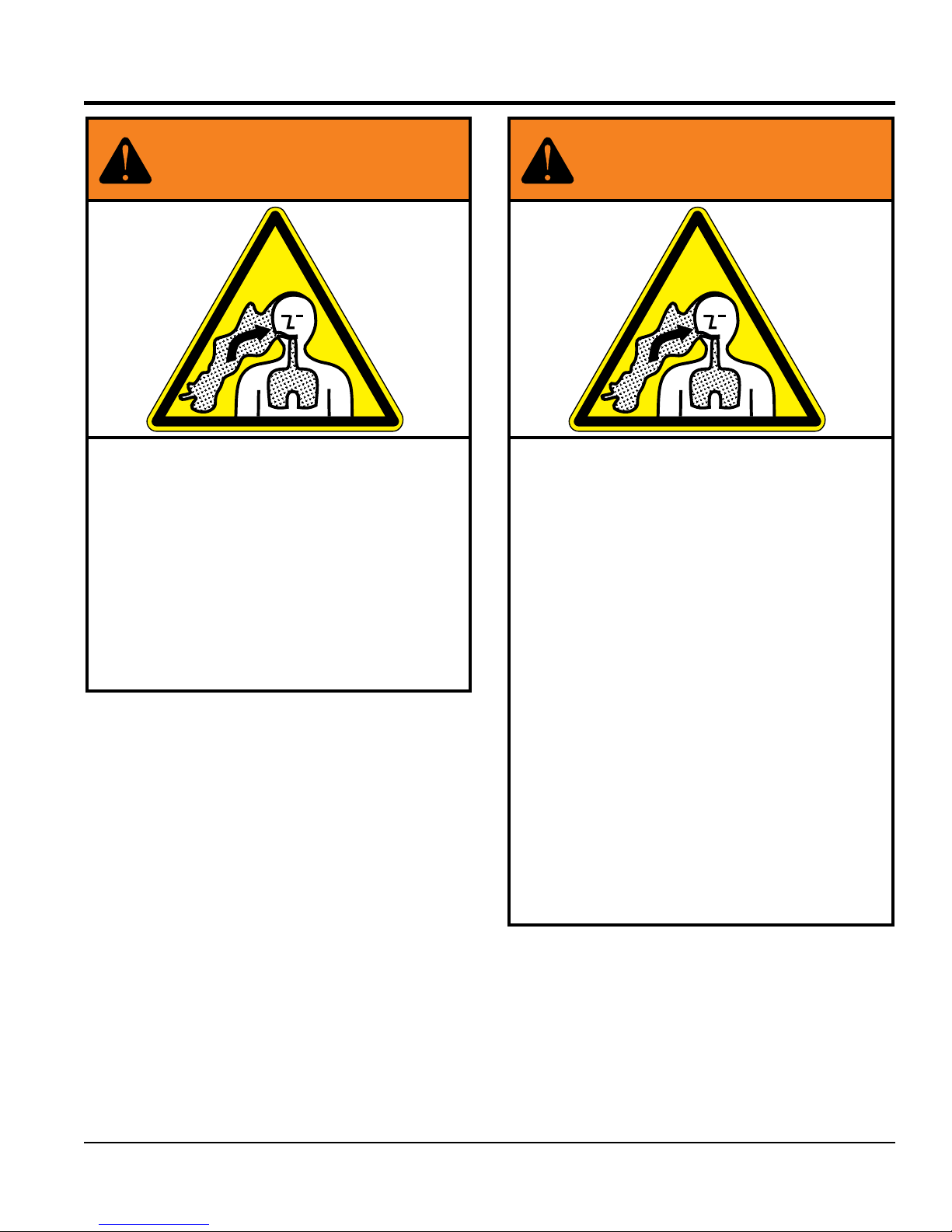
Inhaling exhaust fumes can result in severe
injury or death.
Only operate equipment in well ventilated areas.
Gasoline fuel can cause fire or explosion. Stop
engine before refueling.
Keep cigarettes, sparks and flames away from hot
surfaces.
HOT PARTS can burn skin.
DO NOT
amount of time to cool before performing maintenance.
SAFETY HAZARD
WARNING
Lethal Exhaust Gas Hazard
inhale exhaust gases/fumes.DO NOT
WARNING
Explosive Fuel Hazard
CAUTION
Burn Hazard
touch hot parts. Allow machine a sufficient
Warning decals associated with the operation of this
equipment are defi ned below:
CAUTION
Indicates a hazardous situation which, if not avoided,
COULD result in MINOR or MODERATE INJURY.
NOTICE
Addresses practices not related to personal injury.
WARNING
Rotating Blade Hazard
Keep hands and feet clear of guard rings.
Stop engine before servicing.
To avoid injury you must read and
understand operator’s manual before
using this machine.
MQS36H SERIES WALK-BEHIND TROWEL • OPERATION AND PARTS MANUAL — REV. #0 (03/08/12) — PAGE 7
GENERAL SAFETY
NOTICE
This equipment should only be operated by trained and
Whenever necessary, replace nameplate, operation and
accident due to equipment modifi cations. Unauthorized
recommended by Multiquip for this equipment. Damage
keep
Also, know the phone numbers
fi re department.
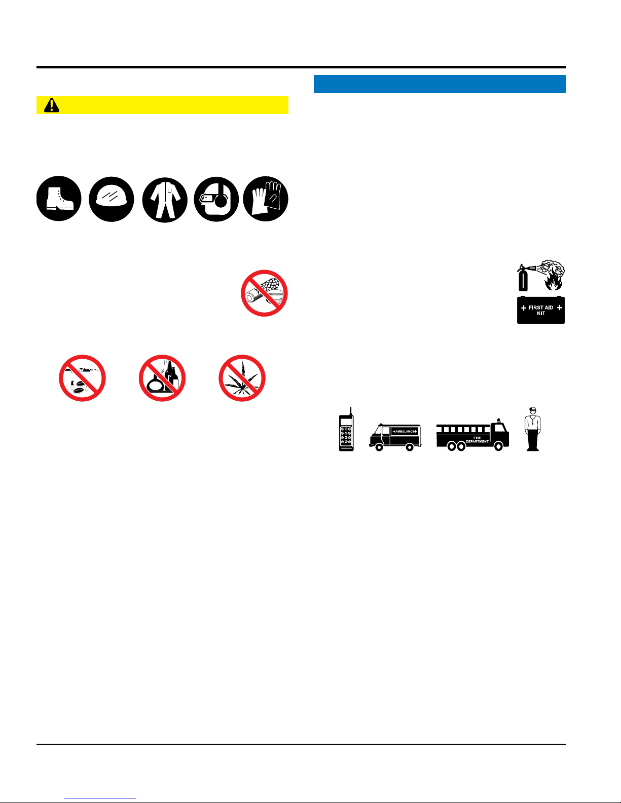
SAFETY INFORMATION
CAUTION
NEVER operate this equipment without proper protective
clothing, shatterproof glasses, respiratory protection,
hearing protection, steel-toed boots and other protective
devices required by the job or city and state regulations.
Avoid wearing jewelry or loose fi tting clothes that may
snag on the controls or moving parts as this can cause
serious injury.
NEVER operate this equipment when not
feeling well due to fatigue, illness or when
under medication.
NEVER operate this equipment under the
infl uence of drugs or alcohol.
ALWAYS clear the work area of any debris, tools, etc.
that would constitute a hazard while the equipment is
in operation.
qualifi ed personnel 18 years of age and older.
safety decals when they become diffi cult read.
Manufacturer does not assume responsibility for any
equipment modifi cation will void all warranties.
NEVER use accessories or attachments that are not
to the equipment and/or injury to user may result.
ALWAYS know the location of the nearest
fi re extinguisher.
ALWAYS know the location of the nearest
fi rst aid kit.
ALWAYS know the location of the nearest phone or
a phone on the job site.
of the nearest ambulance, doctor and
This information will be invaluable in the case of an
emergency.
No one other than the operator is to be in the working
area when the equipment is in operation.
DO NOT use the equipment for any purpose other than
its intended purposes or applications.
PAGE 8 — MQS36H SERIES WALK-BEHIND TROWEL • OPERATION AND PARTS MANUAL — REV. #0 (03/08/12)
TROWEL SAFETY
NOTICE
keep the machine in proper running condition.
store equipment properly when it is not being
used. Equipment should be stored in a clean, dry location
out of the reach of children and unauthorized personnel.
Association of Equipment Manufacturers (AEM) can be
engine is hot. High pressure boiling water will gush out
SAFETY INFORMATION
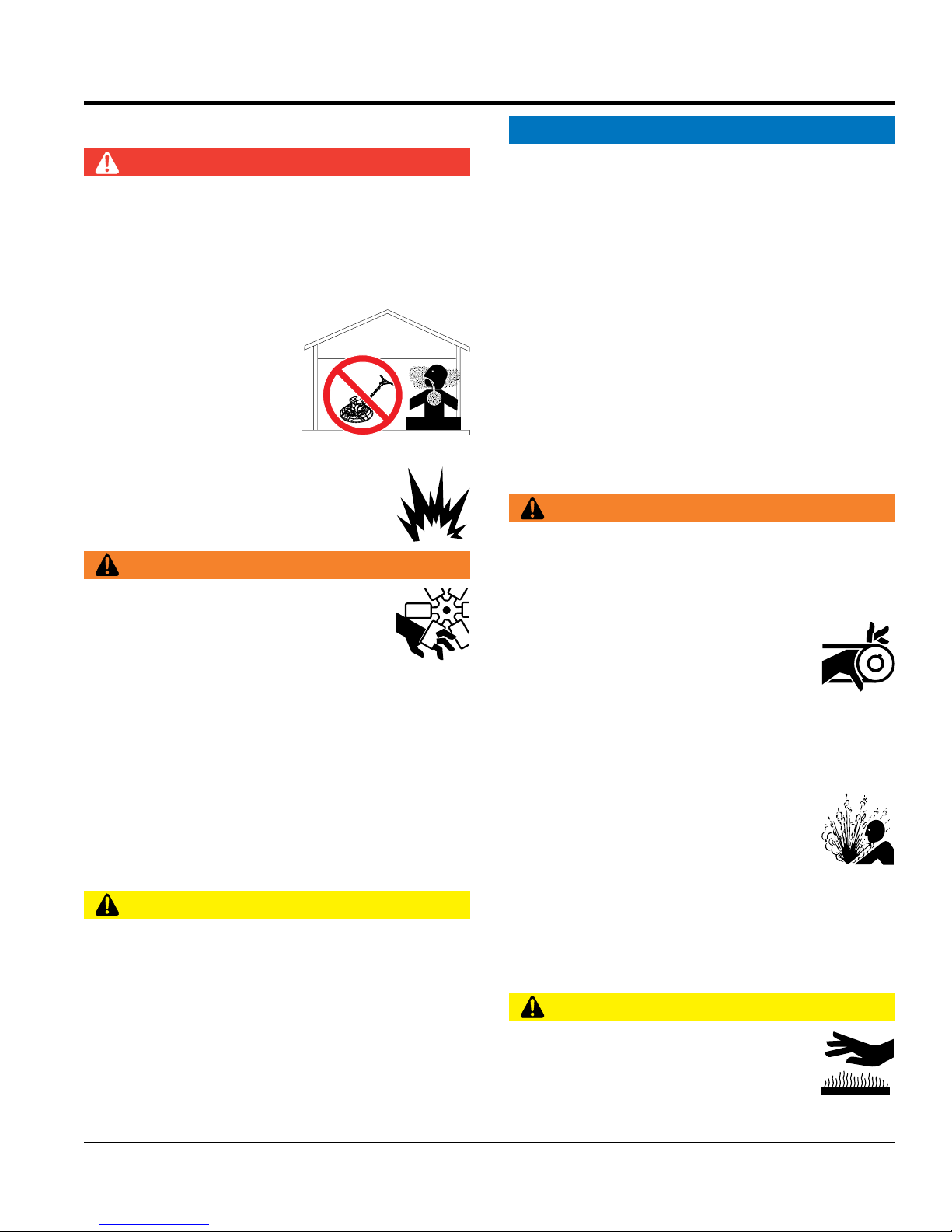
DANGER
Engine fuel exhaust gases contain poisonous carbon
monoxide. This gas is colorless and odorless, and can
cause death if inhaled.
The engine of this equipment requires an adequate free
fl ow of cooling air. NEVER operate this equipment in any
enclosed or narrow area
where free fl ow of the air is
restricted. If the air fl ow is
restricted it will cause injury
to people and property and
serio u s dama g e to t he
equipment or engine.
NEVER operate the equipment in an explosive
atmosphere or near combustible materials. An
explosion or fi re could result causing severe
bodily harm or even death.
WARNING
ALWAYS keep clear of rotating or moving
parts while operating the trowel.
ALWAYS
Fix damage to machine and replace any broken parts
immediately.
ALWAYS
A safety manual for operating and maintenance
personnel of concrete power trowels produced by the
DANGEROUS
GAS FUMES
obtained for a fee by ordering through their website at
www.aem.org.
Order FORM PT-160
ENGINE SAFETY
WARNING
D O NOT pl ace hands o r fi ngers inside e ngine
compartment when engine is running.
NEVER operate the engine with heat shields or
guards removed.
DO NOT start or operate the trowel if the
drive train will not disengage. Centrifugal
force between the trowel and surface when starting can
cause uncontrolled handle movement that can cause
serious injury. The handle must not move while pulling
the engine recoil starter.
NEVER disconnect any emergency or safety devices.
These devices are intended for operator safety.
Disconnection of these devices can cause severe injury,
bodily harm or even death. Disconnection of any of these
devices will void all warranties.
CAUTION
NEVER stand on trowel during operation.
NEVER lubricate components or attempt service on a
running machine.
NEVER place your feet or hands inside the guard rings
while starting or operating this equipment.
Keep fi ngers, hands hair and clothing away
from all moving parts to prevent injury.
DO NOT remove the radiator cap while the
of the radiator and severely scald any persons in the
general area of the trowel.
DO NOT remove the coolant drain plug
while the engine is hot. Hot coolant will
gush out of the coolant tank and severely
scald any persons in the general area of
the trowel.
DO NOT remove the engine oil drain plug while the
engine is hot. Hot oil will gush out of the oil tank and
severely scald any persons in the general area of the
trowel.
CAUTION
NEVER touch the hot exhaust manifold,
muffl er or cylinder. Allow these parts to cool
before servicing equipment.
MQS36H SERIES WALK-BEHIND TROWEL • OPERATION AND PARTS MANUAL — REV. #0 (03/08/12) — PAGE 9
NOTICE
Store fuel in appropriate containers, in well-ventilated
Some walk-behind trowels can be lifted or moved by two
people utilizing lifting tubes or other special attachments.
Generally, however, they must be lifted using lifting bales
transport trowel with fl oat pans attached unless
safety catches are used and are specifi cally cleared for
NEVER run engine without an air fi lter or with a dirty air
fi lter. Severe engine damage may occur. Service air fi lter
frequently to prevent engine malfunction.
NEVER tamper with the factory settings
of the engine or engine governor. Damage
to the engine or equipment can result
if operating in speed ranges above the
maximum allowable.
FUEL SAFETY
DANGER
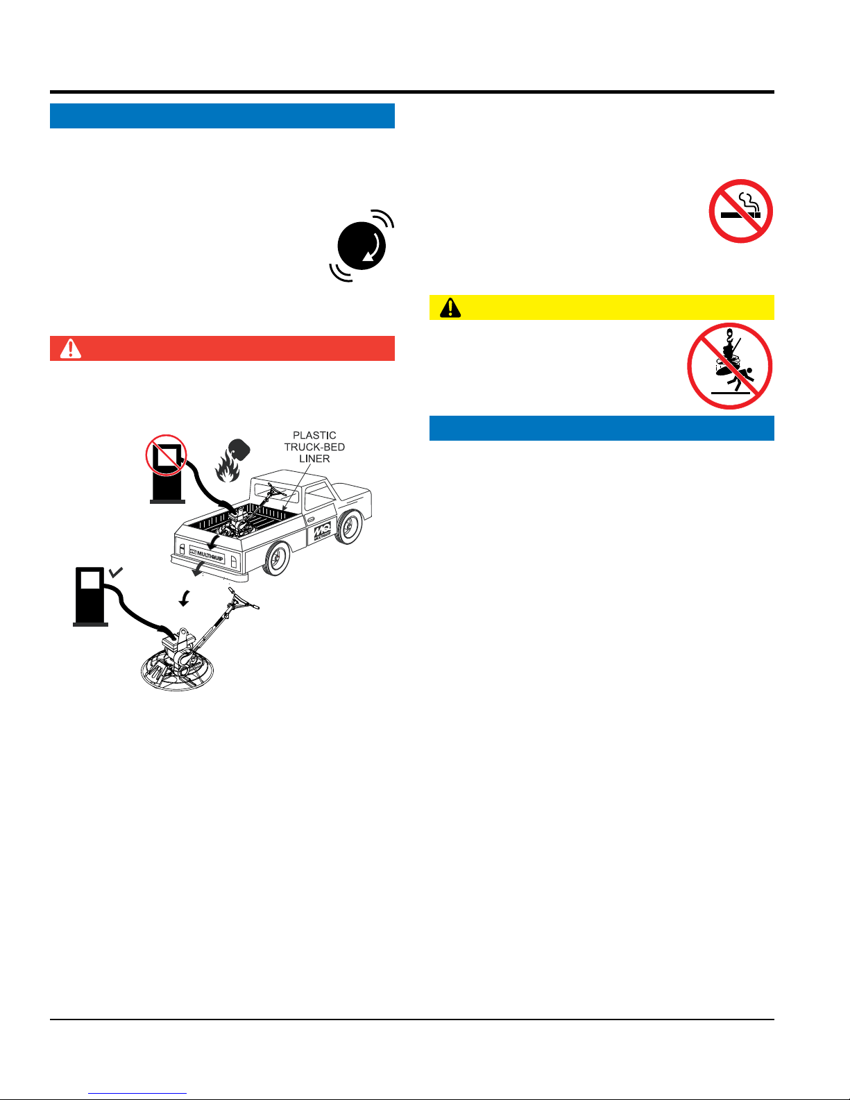
DO NOT add fuel to equipment if it is placed inside truck
bed with plastic liner. Possibility exists of explosion or
fi re due to static electricity.
SAFETY INFORMATION
areas and away from sparks and fl ames.
NEVER use fuel as a cleaning agent.
D O NOT smoke around or near the
equipment. Fire or explosion could result
from fuel vapors or if fuel is spilled on a
hot engine.
TRANSPORTING SAFETY
CAUTION
NEVER allow any person or animal to
stand underneath the equipment while
lifting.
NOTICE
FUEL
FUEL
DO NOT start the engine near spilled fuel or combustible
fl uids. Fuel is extremely fl ammable and its vapors can
cause an explosion if ignited.
ALWAYS refuel in a well-ventilated area, away from
sparks and open fl ames.
ALWAYS use extreme caution when working with
fl ammable liquids.
DO NOT fi ll the fuel tank while the engine is running
or hot.
DO NOT overfi ll tank, since spilled fuel could ignite if it
comes into contact with hot engine parts or sparks from
the ignition system.
and cranes, hoists, or forklifts.
NEVER
such transport by the manufacturer.
NEVER hoist the trowel more than three feet off the
ground with fl oat pans attached.
Before lifting, make sure that the lifting bales are not
damaged.
Always make sure crane or lifting device has been
properly secured to the lifting bales of the equipment.
ALWAYS shutdown engine before transporting.
NEVER lift the equipment while the engine is running.
Tighten fuel tank cap securely and close fuel cock to
prevent fuel from spilling.
Use adequate lifting cable (wire or rope) of suffi cient
strength.
DO NOT lift machine to unnecessary heights.
ALWAYS tie down equipment during transpor t by
securing the equipment with rope.
PAGE 10 — MQS36H SERIES WALK-BEHIND TROWEL • OPERATION AND PARTS MANUAL — REV. #0 (03/08/12)

SAFETY INFORMATION
ENVIRONMENTAL SAFETY/DECOMMISSIONING
EMISSIONS INFORMATION
This engine has been certifi ed to meet US EPA Evaporative
proper training could damage the equipment or create an
Additionally, modifying the fuel system may adversely affect
evaporative emissions, resulting in fi nes or other penalties.
The emission control label is an integral part of the emission
If a replacement emission label is needed, please contact
NOTICE
Decommissioning is a controlled process used to safely
retire a piece of equipment that is no longer serviceable.
If the equipment poses an unacceptable and unrepairable
safety risk due to wear or damage or is no longer cost
effective to maintain (beyond life-cycle reliability) and is to
be decommissioned (demolition and dismantlement),be
sure to follow rules below.
DO NOT pour waste or oil directly onto the ground, down
a drain or into any water source.
Contact your country's Depar tment of
Public Works or recycling agency in your
area and arrange for proper disposal of
any electrical components, waste or oil
associated with this equipment.
When the life cycle of this equipment is over, remove
battery and bring to appropriate facility for lead
reclamation. Use safety precautions when handling
batteries that contain sulfuric acid.
When the life cycle of this equipment is over, it is
recommended that the trowel frame and all other metal
parts be sent to a recycling center.
Metal recycling involves the collection of metal from
discarded products and its transformation into raw
materials to use in manufacturing a new product.
Recyclers and manufacturers alike promote the process
of recycling metal. Using a metal recycling center
promotes energy cost savings.
NOTICE
The gasoline engine used in this equipment has been
designed to reduce harmful levels of carbon monoxide
(CO), hydrocarbons (HC) and nitrogen oxides (NOx)
contained in gasoline exhaust emissions.
emissions requirements in the installed confi guration.
Attempting to modify or make adjustments to the engine
emmission system by unauthorized personnel without
unsafe condition.
Emission Control Label
system and is strictly controlled by regulation(s).
The label must remain with the engine for its entire life.
your authorized Honda Engine Distributor.
MQS36H SERIES WALK-BEHIND TROWEL • OPERATION AND PARTS MANUAL — REV. #0 (03/08/12) — PAGE 11
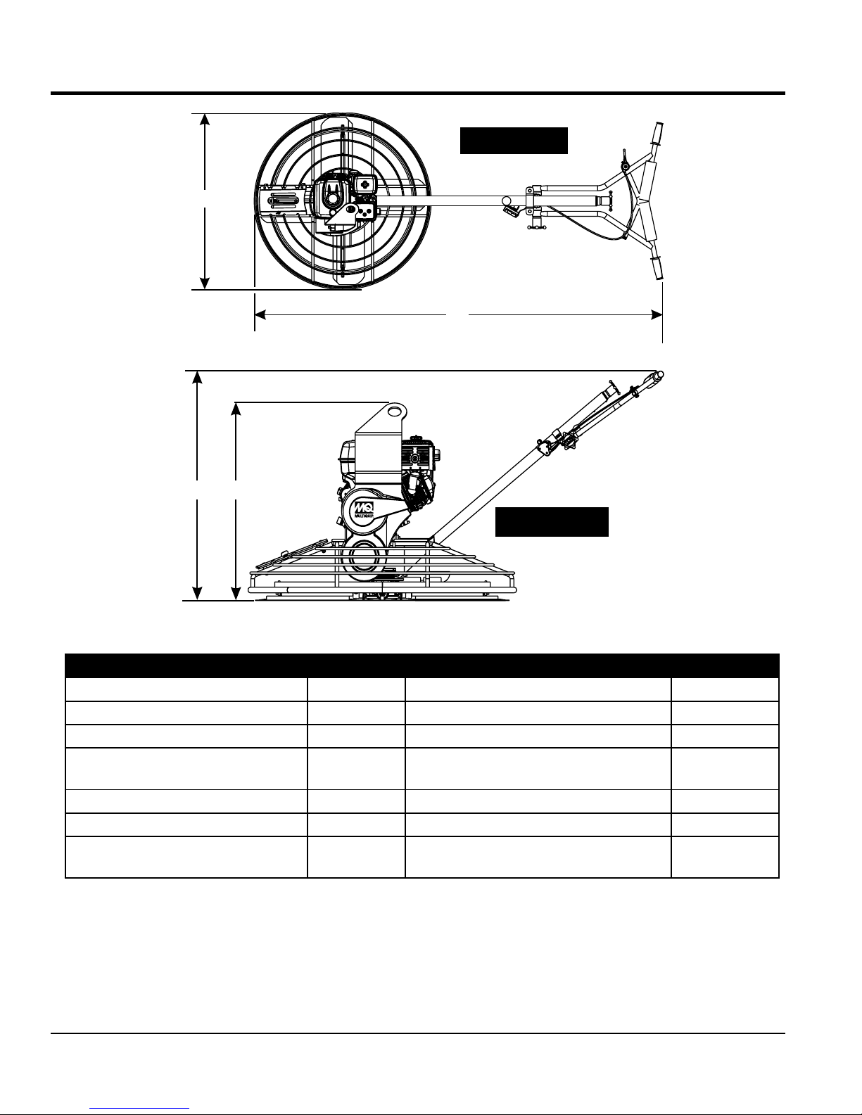
TROWEL SPECIFICATIONS/DIMENSIONS
AAA
B
SIDE VIEW
TOP VIEW
C
D
A–Height (Lifting Bale) – in. (mm) 27 (686) Sound Pressure (Guaranteed) – dBA
B–Height (Handle) – in. (mm) 37.4 (950) Vibration (Hand/Arm) – ft/s
C–Width (Ring Diameter) – in. (mm) 40 (1,016) Engine – H.P. 5.5/9.0
D–Length – in. (mm) 74 (1,880)
Number of Blades 4 Ring Diameter – in. (mm) 37.38 (950)
Path Width – in. (mm) 34.5 (876) Gear Box Oil Capacity – oz. (ml) 44 (1,300)
Sound Pressure (Weighted) – dBA
2
1. Sound pressure is “A” weighted . Measured at the
operators ear position while the walk-behind trowel is
operating at full throttle on concrete in a manner most
often experienced in “normal ” circumstances. Sound
pressure may vary depending upon the condition of the
concrete. Hearing protection is always recommended.
Figure 1. Dimensions
Table 1. Trowel Specifications
Rotor – RPM (Dry Concrete) MQS36H55
Rotor – RPM (Dry Concrete) MQS36H90H
109
Shipping Weight – lbs. (kg.) MQS36H55
Shipping Weight – lbs. (kg.) MQS36H90H
2. The vibration level indicated is the maximum RMS
(Root Mean Square) value obtained at the handle
grip while operating the ride-on trowel on curing
concrete in a manner most often experienced in
“normal ” circumstances. Values were obtained from
all three axes of motion. The values shown represent
the maximum RMS value from these measurements.
2
(m/s2)
2
1
94
62 (19.0)
60-130
90-150
225 (102)
235 (107)
PAGE 12 — MQS36H SERIES WALK-BEHIND TROWEL • OPERATION AND PARTS MANUAL — REV. #0 (03/08/12)

ENGINE SPECIFICATIONS
Table 2. Engine Specifications/Dimensions
Model
Type
Bore X Stroke 2.70 in. X 1.8 in. (68 mm x 45 mm) 3.0 in. X 2.3 in. (77 mm x 58 mm)
Displacement 9.9 cu-in. (163 cc) 16.4 cu-in. (270 cc)
Max. Output 5.5 H.P. @ 3600 RPM 9.0 H.P. @ 3600 RPM
Fuel Tank Capacity Approx. 0.95 U.S. Gallons (3.6 Liters) Approx. 1.95 U.S. Gallons (6.0 Liters)
Fuel Unleaded Gasoline Unleaded Gasoline
Lube Oil Capacity 0.63 qt. (0.6 liters) 1.06 qt. (1.1 liters)
Oil Type
Speed Control Method Centrifugal Fly-weight Type Centrifugal Fly-weight Type
Cooling System Forced Air Forced Air
Starting Method Recoil Start Recoil Start
Spark Plug Type BPR6ES NGK BPR6ES NGK
Spark Plug Gap 0.028-0.031 in. (0.70 - 0.80 mm) 0.028-0.031 in. (0.70 - 0.80 mm)
Dimension (L x W x H) 12.3 x 14.3 X 13.2 in. (312 X 362 X 335 mm) 15.0 x 16.8 X 16.6 in. (381 X 428 X 422 mm)
Honda GX160UT1QX2T Engine
(MQS36H55)
Air-cooled 4 stroke, Single Cylinder, OHV,
Horizontal Shaft Gasoline Engine
4-Stroke API, SF or SG
SAE 10W-30 General Use
Honda GX2700UTQA2 Engine
(MQS36H90H)
Air-cooled 4 stroke, Single Cylinder, OHV,
Horizontal Shaft Gasoline Engine
4-Stroke API, SF or SG
SAE 10W-30 General Use
Dry Net Weight 33.1 lbs (15 Kg.) 55.1 lbs (25 Kg.)
MQS36H SERIES WALK-BEHIND TROWEL • OPERATION AND PARTS MANUAL — REV. #0 (03/08/12) — PAGE 13

GENERAL INFORMATION
INTENDED USE
Operate this trowel, tools and components in accordance
with the manufacturer's instructions. Use of any other tools
for stated operation is considered contrary to designated
use. The risk of such use lies entirely with the user. The
manufacturer cannot be held liable for damages as a result
of misuse
TROWEL FAMILIARIZATION
This walk-behind trowel is designed for the floating and
finishing of concrete slabs.
Take a walk around the trowel. Take notice of all the major
components (Figure 2) like the engine, blades, steering
handle, kill switch, gearbox, etc. Check that there is always
oil in the engine.
Read all the safety instructions carefully. Safety instructions
will be found throughout this manual and on the trowel. Keep
all safety information in good, readable condition. Operators
should be well trained on the operation and maintenance
of the trowel.
Before using your trowel, test it on a flat watered down
section of finished concrete that is free of any debris and
other objects.
GEARBOX
The gearbox is located beneath the engine and transfers
power to the spider assembly. The gearbox controls the
rotational speed of the trowel and is equipped with two
shafts (input and output).
SPIDER
The vertical output shaft of the gearbox connects to a cast
hub called the spider. The spider has 4 arms that extend
outward that are used for attachment of blades or other
accessories. Remember as the gearbox output shaft rotates
so does the spider assembly.
GUARD RING
This unit is equipped with a safety guard ring. It is designed
to help protect items from coming into contact with the
rotating blades while the trowel is in operation.
BLADES
The blades of the trowel finish the concrete as they are
rotated around the surface. This trowel comes equipped
with four combination blades (8 in./203 mm wide) per
rotor equally spaced in a radial pattern and attached to a
vertical rotating shaft by means of a spider assembly.
This trial test run will increase your confidence in using the
trowel and at the same time it will familiarize you with the
trowel’s controls. In addition you will understand how the
trowel handles under actual conditions.
ENGINE
This trowel is equipped with either a HONDA 5.5 or 9.0 HP
gasoline engine. Refer to the engine owner’s manual for
instructions regarding the operation and maintenance of
your engine. Please contact your nearest Multiquip Dealer
for a replacement should the original manual disappear or
otherwise become unusable.
DRIVE SYSTEM
Power is transferred from the engine to the gearbox input
shaft via a V-belt pulley drive system. The pulley engages
using a centrifugal clutch. See parts section of this manual
for a breakdown of the drive system.
CENTRIFUGAL
In the event of a trowel runaway condition (operator
releases handlebars during operation), the centrifugal
safety stop switch will stop the engine and bring the trowel
to a halt
CAUTION
NEVER attempt to lift the trowel by yourself. ALWAYS get
the assistance of another person to help lift the trowel.
SAFETY STOP SWITCH
TRAINING
For proper training, please use the “TRAINING CHECKLIST”
form located in the front of this manual. This checklist will
provide an outline for an experienced operator to provide
training to a new operator.
PAGE 14 — MQS36H SERIES WALK-BEHIND TROWEL • OPERATION AND PARTS MANUAL — REV. #0 (03/08/12)
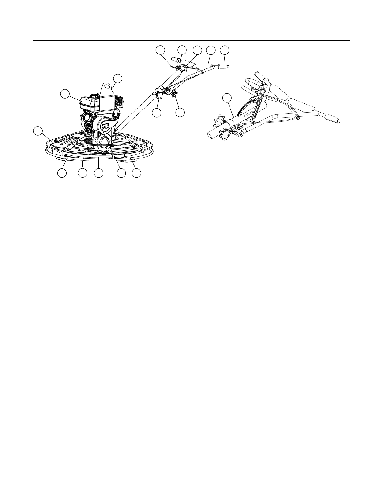
TROWEL COMPONENTS
4 5
3
2
10
1
15
Figure 2. Trowel Control and Components
14
111213
9
Figure 2 shows the location of the basic controls or
components, for the trowel. Listed below is a brief
explanation of each control or component.
1. Access Panel — Allows access to the blade area.
NEVER run the trowel with this access panel removed.
2. Engine — Honda 5.5 or 9.0 HP gasoline engine.
3. Lifting Bale — Attach a suitable lifting device to lifting
bale whenever lifting of the trowel is required.
4. Throttle Lever — Controls engine speed. Returns
engine to idle when released.
5. Vibratory Handle Bar — Installed rubber shock
mounts/isolators reduces vibration when the trowel
is operating.
6. Pitch Control Star Wheel— To adjust the pitch of the
blades, rotate the star wheel clockwise to pitch blades
upwards. Rotate star wheel counterclockwise to pitch
blades flat (no pitch).
7. Handle Bar Pad — Foam rubber pad that protects the
body when coming in contact with handle bar.
8. Hand Grips — When maneuvering of the trowel is
required ALWAYS place both hands on each grip to
operate the trowel. Replace hand grips when they
become worn or damaged.
6
8
7
16
QUICK PITCH ™
HANDLE
(OPTION)
9. Handlebar Adjuster — Change the angle/height of the
handle bars by loosening star wheel, adjust handlebars
to desired location, tighten starwheel firmly to hold
handlebars in that position.
10. Centrifugal "Kill" Switch — In the event the operator
loses control of the trowel, this switch will shut down
the engine.
11. Blades — This trowel is equipped with combination
blades. These blades are versatile and should take
care of most troweling needs. In addition float discs
can be attached to the trowel arms that will allow the
trowel to float on "wet" concrete.
12. V-Belt Cover — Remove this cover to gain access to
the V-belt. NEVER operate the trowel with this cover
removed.
13. Guard Ring — NEVER put hands or feet inside guard
ring while the machine is running.
14. Gearbox — Helical worm gear drive gearbox. Provides
rotation of blades via engine interface. ALWAYS check
gearbox oil level (sight glass) prior to each use. Fill with
recommended type gearbox oil.
15. Trowel Arm — NEVER operate the trowel with a bent,
broken or out of adjustment trowel arm. If the blades
show uneven wear patterns or some blades wear out
faster than others, the trowel arm may need to be
adjusted. Use the trowel arm adjustment tool P/N 1817
to adjust the trowel arms.
16. Quick Pitch™ Control Handle — Contact MQ unit
sales for this option.
MQS36H SERIES WALK-BEHIND TROWEL • OPERATION AND PARTS MANUAL — REV. #0 (03/08/12) — PAGE 15
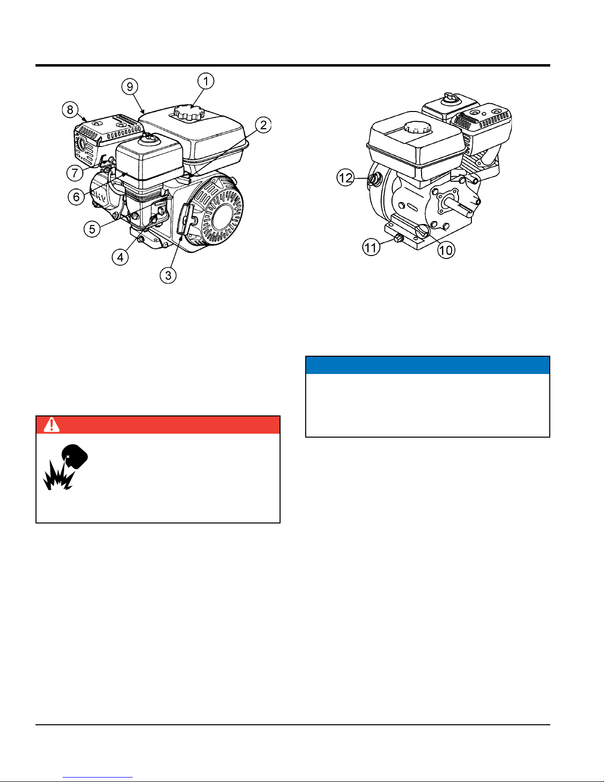
ENGINE COMPONENTS
INITIAL SERVICING
The engine (Figure 3) must be checked for proper
lubrication and filled with fuel prior to operation. Refer to the
manufacturer's engine manual for instructions and details
of operation and servicing.
1. Fuel Filler Cap – Remove this cap to add unleaded
gasoline to the fuel tank. Make sure cap is tightened
securely. DO NOT over fill.
DANGER
Add fuel to the tank only when the engine
is stopped and has had an opportunity to
cool down. In the event of a fuel spill, DO
NOT attempt to start the engine until the
fuel residue has been completely wiped up
and the area surrounding the engine is dry.
2. Throttle Lever – Used to adjust engine RPM speed.
This lever is connect to the throttle lever cable located
on the handle bars. Reference throttle cable installation
procedure in this manual.
3. Recoil Starter (pull rope) – Manual-starting method.
Pull the starter grip until resistance is felt, then pull
briskly and smoothly.
4. Fuel Valve Lever – OPEN to let fuel flow, CLOSE to
stop the flow of fuel.
5. Choke Lever – Used in the starting of a cold engine,
or in cold weather conditions. The choke enriches the
fuel mixture.
Figure 3. Engine Controls and Components
6. Air Cleaner – Prevents dirt and other debris from
entering the fuel system. Remove wing-nut on top of
air filter canister to gain access to filter element.
NOTICE
Operating the engine without an air filter, with a
damaged air filter, or a filter in need of replacement
will allow dirt to enter the engine, causing rapid engine
wear.
7. Spark Plug – Provides spark to the ignition system.
Set spark plug gap according to engine manufacturer's
instructions. Clean spark plug once a week.
8. Muffler – Used to reduce noise and emissions. NEVER
touch when hot!
9. Fuel Tank – Fill with unleaded gasoline. Reference
Table 2 for fuel tank capacity. For additional information
refer to Honda engine owner's manual.
10. Dipstick/Oil Filler Cap – Remove this cap to determine
if the engine oil is low. Add oil through this filler port as
recommended in Table 3.
11. Oil Drain Plug – Remove this plug to remove oil from
the engine's crankcase.
12. Engine ON/OFF Switch – ON position permits engine
starting, OFF position stops engine operation.
PAGE 16 — MQS36H SERIES WALK-BEHIND TROWEL • OPERATION AND PARTS MANUAL — REV. #0 (03/08/12)
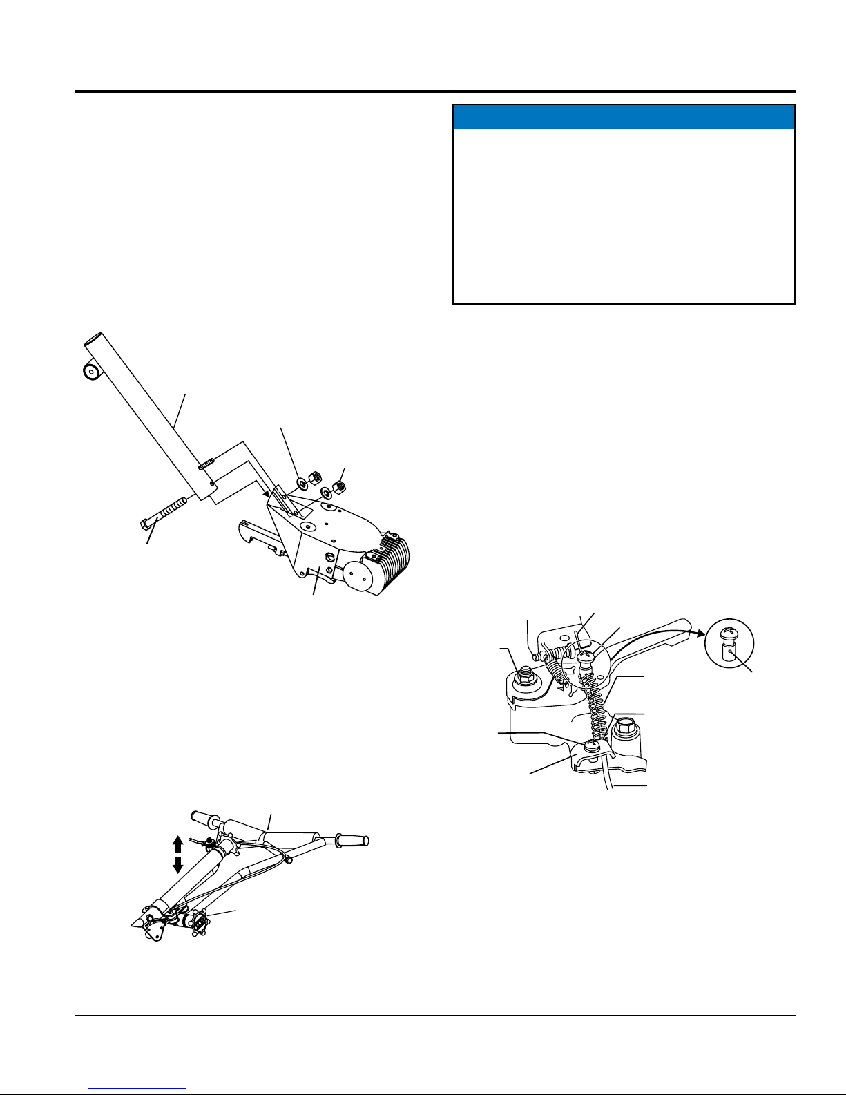
ASSEMBLY AND INSTALLATION
GEARBOX
ASSEMBLY AND INSTALLATION
Before the trowel can be put into operation there are some
components that must be installed before the trowel can
be used. This section provides general instructions on how
to install those components. Instruction sheet P/N 20485
provides further details for the handle assembly.
Handle Tube Installation
1. Attach the main handle (tube) to the gearbox as shown
in (Figure 4). The mounting hardware should be
contained in the shipping container.
MAIN HANDLE
(TUBE)
3/8 FLAT
WASHER
3/8-16
NYLOC NUT
3/8-16 X 3.25
HHC SCREW
Figure 4. Handle Tube Installation
Vibratory T-Handle Bar Placement
1. The vibratory T-handle bar is already attached to the
main handle tube.
2. To adjust the height of the T-bar, loosen the star wheel
(Figure 5) and position T-handle bar in the desired
position.
T-HANDLE BAR
NOTICE
If additional handle height adjustment is desired, a
handle wedge kit can be purchased for your trowel by
ordering P/N 2576 from your Multiquip dealer.
These wedges are placed between the handle and the
gearbox to adjust the operating height of the handle.
This kit comes complete with wedges, new bolts and
installation instructions. This will move your operating
handle position up or down approximately 3” (76 mm).
Throttle Cable Installation (Engine)
1. Uncoil the throttle cable and housing.
2. Feed the throttle cable through the cable housing.
3. Connect the trowel throttle cable to the engine
throttle linkage (Figure 6). There should be a piece
of wire installed on the trowel to show where to route
the throttle cable.
4. Route cable end through the idle control spring and
swivel stop. When connecting the cable housing,
make sure that no more than 1/4" (6.4 mm) of the cable
housing protrudes past the housing clamp on the
engine.
CABLE
END
SWIVEL
ADJUSTER
NUT
CLAMP
SCREW
CABLE
HOUSING
CLAMP
STOP
IDLE
RETURN
SPRING
CABLE
HOUSING
END
TROWEL
THROTTLE
CABLE
SWIVEL
STOP HOLE
HEIGHT
ADJUSTMENT
STAR WHEEL
Figure 5. T-Handle Bar Adjustment
3. Tighten star wheel firmly.
MQS36H SERIES WALK-BEHIND TROWEL • OPERATION AND PARTS MANUAL — REV. #0 (03/08/12) — PAGE 17
Figure 6. Throttle Cable Installation (Engine)
5. Tighten cable clamp screw and swivel stop screw.
6. After the trowel throttle cable has been connected to
the engine throttle linkage, adjust and tighten operator
position of the T-bar handle to lock the throttle cable at
the proper length.
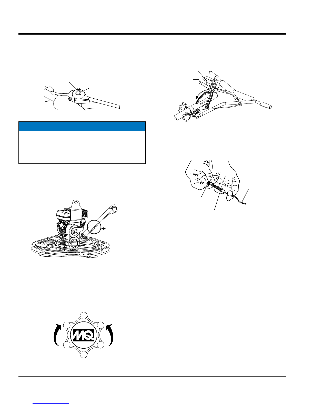
ASSEMBLY AND INSTALLATION
7. Adjustment of the throttle cable tension may be
required. If so, loosen the adjusting nut (top nut) on
the throttle cable receiver (Figure 7) and loosen or
tighten the locking nut (bottom nut). Retighten
adjusting nut.
ADJUSTING
NUT (TOP)
LOCKING NUT
(BOTTOM)
Figure 7. Throttle Cable Receiver Adjustment
NOTICE
If the throttle lever does not return to the "neutral"
position with throttle backed off, loosen adjuster nut 1/2
turn at a time, tighten and recheck. Readjust throttle
tension as necessary.
Safety Stop Switch Connection
1. Connect the black tail wire from the engine to the black
safety stop wire from the centrifugal stop switch as
shown in Figure 8.
SAFETY STOP WIRE
CONNECTION POINT
2. For Quick Pitch™ Handle models expose the pitch
cable to maximum by grasping the T-handle (Figure 10),
then squeezing the trigger lock and pushing the
T-handle forward for no pitch (blades flat).
T-HANDLE
TRIGGER
(SQUEEZE)
NO PITCH
FORWARD
Figure 10. Blade Pitch T-Handle
(Quick Pitch™ Handle)
3. Remove brass set nut #1 from the blade pitch cable
end as shown in (Figure 11).
BLADE
PITCH
CABLE
BRASS SET
NUT #1
BRASS SET
NUT #2
Figure 11. Blade Pitch Cable
4. Thread brass set nut #2 (Figure 11) towards the cable
as far as possible.
5. Insert t he cabl e end t hrough th e yoke eyel et
Figure 8. Safety Stop Switch Connection
(Figure 12). Tighten brass set nut #1 by hand to remove
all the slack from the cable.
Pitch Cable Installation
1. For Standard Handle models expose the pitch cable
to maximum by turning the blade pitch star wheel
(Figure 9) fully counterclockwise for no pitch (blades
flat).
INCREASE
BLADE PITCH
(CW)
Figure 9. Blade Pitch Star Wheel
(Standard Handle)
PAGE 18 — MQS36H SERIES WALK-BEHIND TROWEL • OPERATION AND PARTS MANUAL — REV. #0 (03/08/12)
DECREASE
BLADE PITCH
(CCW)
BLADE
PITCH
CABLE
YOKE
YOKE
EYELET
BRASS SET
NUT #1
BRASS SET
NUT #2
Figure 12. Pitch Cable Yoke Attachment
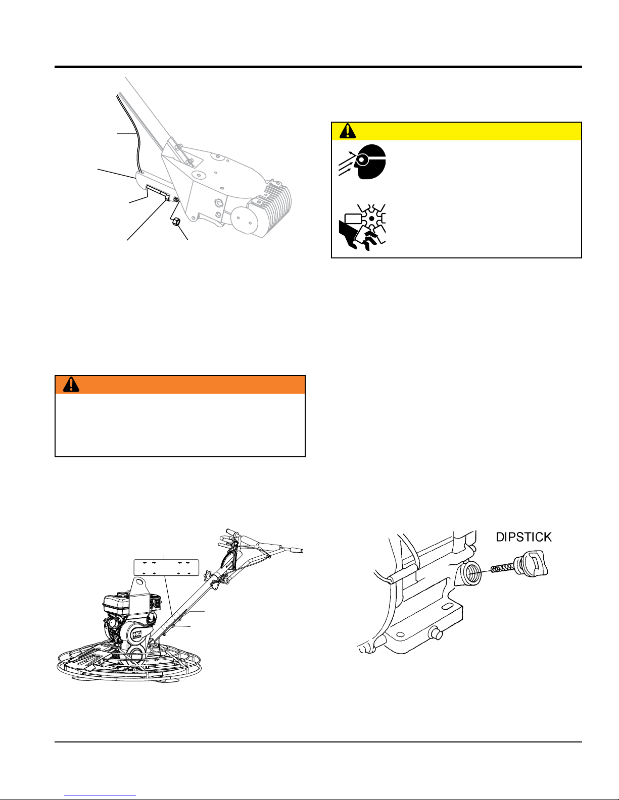
INSPECTION
4. Align the groove on the slider with the text 36" COMBO/
"J" COMBO on the decal. The letter "J" stands for J-36
Walk-Behind Trowel
CAUTION
ALWAYS wear approved eye and hearing
protection before operating the trowel.
NEVER place hands or feet inside the guard
rings while the engine is running. ALWAYS
shut the engine down before performing any
kind of maintenance service on the trowel.
Before Starting
6. Using a wrench, tighten the brass set #2 nut up against
the yoke boss. This will lock the cable in place.
7. Use a wrench and finish tightening the brass set #1
nut up against the yoke boss.
Pre-Load Adjustment (Quick Pitch™ Handle Only)
WARNING
The Quick Pitch™ handle is spring loaded, personal
injury or damage could result from improper handling,
installation or adjustment. Use extreme caution when
installing this component.
1. After the Quick-Pitch™ handle has been installed on
the trowel, spring pre-load adjustment will be required.
2. Locate the spring pre-load adjustment screw (Figure 13)
on the underside of the handle tube.
ALIGNMENT
DECAL
J
FINISH
PRELOAD TRIM INDICATOR
FINISH
36”
J
COMBO
COMBO
COMBO
FINISH
FINISH
COMBO
48”
1. Read all safety instructions at the beginning of manual.
2. Clean the trowel, removing dirt and dust, particularly
the engine cooling air inlet, carburetor and air cleaner.
3. Check the air filter for dirt and dust. If air filter is dirty,
replace air filter with a new one as required.
4. Check carburetor for external dirt and dust. Clean with
dry compressed air.
5. Check fastening nuts and bolts for tightness.
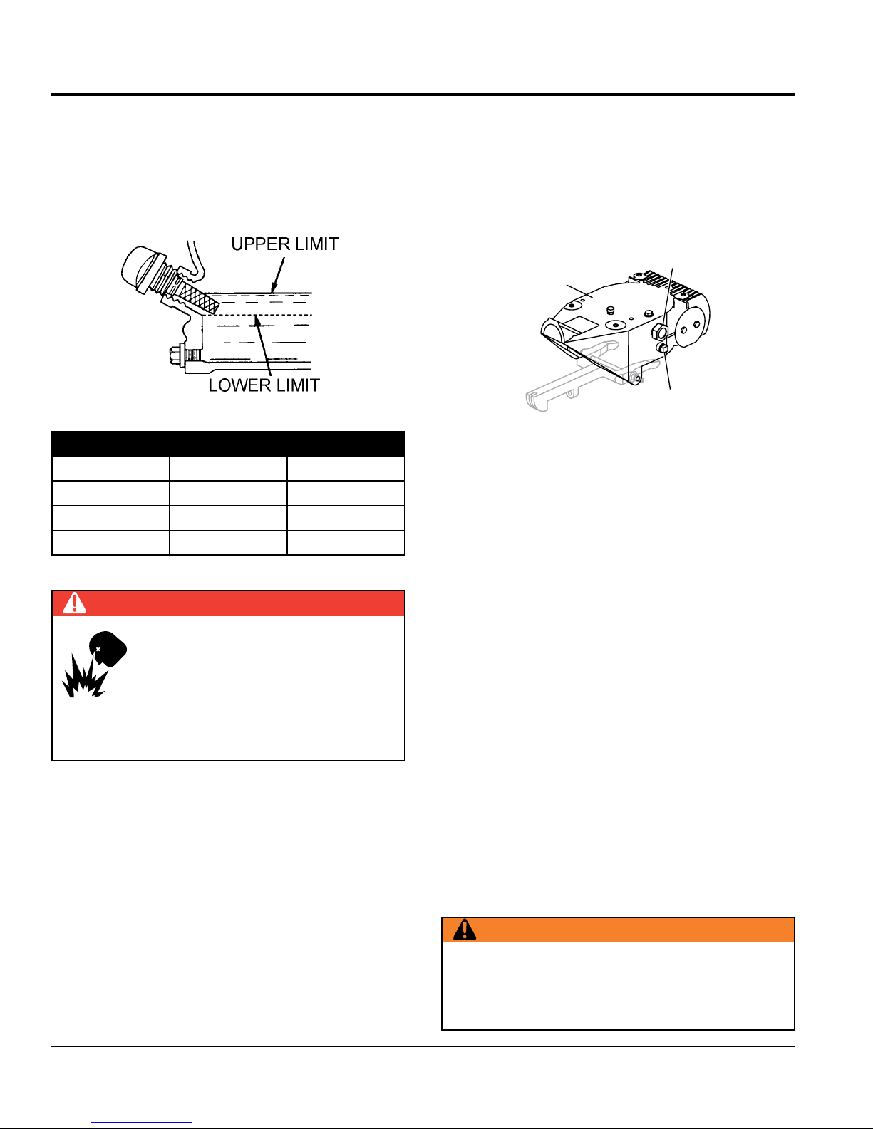
Engine Oil Check
1. To check the engine oil level, place the trowel on secure
level ground with the engine stopped.
2. Remove the dipstick from the engine oil filler hole
(Figure 14) and wipe clean.
ADJUSTMENT
J
FINISH
36”
PRELOADTRIM INDICATOR
FINISH
COMBO
J
FINISH
48”
COMBO
FINISH
COMBO
COMBO
SLIDER
GROOVE
SCREW
Figure 13. Spring Pre-Load Adjustment
3. A decal has been placed on the side of the handle
tube to assist the user in the adjustment of the spring.
MQS36H SERIES WALK-BEHIND TROWEL • OPERATION AND PARTS MANUAL — REV. #0 (03/08/12) — PAGE 19
Figure 14. Engine Oil Dipstick Removal
INSPECTION
3. Insert and remove the dipstick without screwing it into
the filler neck. Check the oil level shown on the dipstick.
4. If the oil level is low (Figure 15), fill to the edge of the
oil filler hole with the recommended oil type as listed
in Table 3. Reference Table 2 for maximum engine oil
capacity.
Figure 15. Engine Oil Dipstick (Oil Level)
Table 3. Oil Type
Season Temperature Oil Type
Summer 25°C or Higher SAE 10W-30
Spring/Fall 25°C~10°C SAE 10W-30/20
Winter 0°C or Lower SAE 10W-10
Gearbox Oil
1. Determine if the gearbox oil is low by removing the oil
plug located on the side of the gearbox. (Figure 16)
This plug will be marked by the "check" decal. The
correct level of the lubrication oil should be to the
bottom of the fill plug.
OIL SIGHT GLASS/
FILL PLUG
GEARBOX
DRAIN
PLUG
Figure 16. Gearbox
2. If lubrication oil begins to seep out as the drain plug
is being removed, then it can be assumed that the
gearbox has a sufficient amount of oil.
3. If lubrication oil does not seep out as the drain plug
is being removed, fill with type ISO 680 (P/N 10139)
gearbox lubricant oil until the oil filler hole overflows.
DANGER
EXPLOSIVE FUEL!
Motor fuels are highly flammable and can
be dangerous if mishandled. DO NOT
smoke while refueling. DO NOT attempt
to refuel the trowel if the engine is hot! or
running.
Fuel Check
1. Visually inspect to see if fuel level is low. If fuel is low,
replenish with unleaded fuel.
2. When refueling, be sure to use a strainer for filtration.
DO NOT top-off fuel. Wipe up any spilled fuel
immediately.
V-Belt Check
A worn or damaged V-belt can adversely affect the
performance of the trowel. If a V-belt is defective or worn
simply replace the V-belt as outlined in the maintenance
section of this manual.
Belt Guard Check
Check for damage, loose or missing hardware.
Blade Check
Check for worn or damaged blades. Check to see if one
blade is worn out while the others look new. If this is
the case there could be a blade pitch problem. Refer to
the maintenance section of this manual for blade pitch
adjustment procedure. Replace any worn blades.
WARNING
NEVER disable or disconnect the centrifugal safety
"STOP" switch. It is provided for operator safety. Injury
may result if it is disabled, disconnected or improperly
maintained.
PAGE 20 — MQS36H SERIES WALK-BEHIND TROWEL • OPERATION AND PARTS MANUAL — REV. #0 (03/08/12)
 Loading...