


OPERATION AND PARTS MANUAL
BA-SERIES
WALK-BEHIND TROWEL
MODEL #
SERIAL #
© COPYRIGHT 2002, MULTIQUIP INC.
Revision #3 (11/30/04)
MULTIQUIP INC
18910 WILMINGTON AVE. 800-427-1244
CARSON, CALIFORNIA 90746 FAX: 800-672-7877
310-537-3700
800-421-1244 800-478-1244
FAX: 310-537-3927 FAX: 310-631-5032
E-mail:mq@multiquip.com • www:multiquip.com
Atlanta • Boise • Dallas • Houston • Newark
Montreal, Canada • Manchester, UK
Rio De Janiero, Brazil • Guadalajara, Mexico
..
. PARTS DEPARTMENT:
..
SERVICE DEPARTMENT/TECHNICAL ASSISTANCE:
P/N 20905


HERE'S HOW TO GET HELP
PLEASE HAVE THE MODEL AND SERIAL NUMBER
ON-HAND WHEN CALLING
PARTS DEPARTMENT
800-427-1244 or 310-537-3700
FAX: 800-672-7877 or 310-637-3284
SERVICE DEPARTMENT/TECHNICAL ASSISTANCE
800-478-1244 or 310-537-3700
FAX: 310- 537-4259
WARRANTY DEPARTMENT
888-661-4279, or 310-661-4279
FAX: 310- 537-1173
MAIN
800-421-1244 or 310-537-3700
FAX: 310-537-3927
BA-SERIES WALK-BEHIND TROWEL — PARTS & OPERATION MANUAL — REV. #3 (11/30/04) — PAGE 3

BA-SERIES TROWEL— TABLE OF CONTENTS
Here's How To Get Help ............................................ 3
Table Of Contents ..................................................... 4
Parts Ordering Procedures ....................................... 5
Training Checklist ...................................................... 6
Daily Pre-Operation Checklist ................................... 7
Safety Message Alert Symbols .............................. 8-9
Rules For Safe Operation .................................. 10-11
Operation And Safety Decals .................................. 12
Specifications (Trowel) ............................................ 13
Specifications (Engines).......................................... 14
Specifications (Trowel Weights) .............................. 14
General Information ................................................ 15
MQ WHITEMAN — BA-SERIES TROWEL
Controls and Components ................................. 16-17
Basic Engine ........................................................... 18
Assembly and Installation .................................. 19-21
Pre-Inspection .................................................... 22-23
Initial Start-Up (Gasoline Engine) ......................24-25
Operation ........................................................... 26-27
Options ............................................................... 28-29
Maintenance ...................................................... 30-34
Troubleshooting (Trowel) ................................... 35-36
Troubleshooting (Engine) ........................................ 37
Explanation of Codes in Remarks Column ............. 38
Suggested Spare Parts ........................................... 39
Nameplate and Decals.......................................40-41
Standard Handle Assy. .......................................42-43
Quick Pitch™ Handle Assy. ............................... 44-46
Thrust Bearing Kit Assy. ..................................... 48-49
4 Blade Spider Assy. .......................................... 50-51
Gearbox and Engine Mounts Assy. ................... 52-54
Engines, Honda, Robin, & Briggs & Stratton ..... 56-57
Hand Clutch Assy. .............................................. 58-59
Guard Ring Assy. ............................................... 60-61
Stabilizer Ring Assy............................................ 62-63
Blades and Adjustment Fixture Assy. ................ 64-65
Lifting Bale Assy. (Option) .................................. 66-67
HONDA GX240K1QA2 ENGINE
Air Cleaner Assy. ................................................ 68-69
Camshaft Assy. .................................................. 70-71
Carburetor Assy. ................................................ 72-73
Control Assy. ...................................................... 74-75
Crankcase Cover Assy. ...................................... 76-77
Crankshaft Assy. ................................................ 78-79
Cylinder Barrel Assy. ..........................................80-81
Cylinder Head Assy. ...........................................82-83
Fan Cover Assy. .................................................84-85
Flywheel Assy..................................................... 86-87
Fuel Tank Assy. .................................................. 88-89
Ignition Coil Assy. ............................................... 90-91
Muffler Assy........................................................ 92-93
Piston Assy. ........................................................ 94-95
Recoil Starter Assy. ............................................ 96-97
Labels ................................................................ 98-99
ROBIN EH25-2 ENGINE
Crankcase Assy. ............................................ 100-101
Crankshaft Assy. ............................................ 102-103
Intake and Exhaust Assy. ...............................104-105
Governor Assy. .............................................. 106-107
Cooling and Starting Assy. ............................. 108-109
Fuel Tank Assy. .............................................. 110-111
Carburetor Assy. ............................................ 112-113
Recoil Start Assy. ...........................................114-115
Oil Sensor Assy. ............................................. 116-117
Terms and Conditions of Sale — Parts ................. 118
NOTE
Specification and part number
are subject to change without
notice.
PAGE 4 — BA-SERIES WALK-BEHIND TROWEL— PARTS & OPERATION MANUAL — REV. #3 (11/30/04)
BA-SERIES TROWEL— PARTS ORDERING PROCEDURES
■■
■ Dealer account number
■■
■■
■ Dealer name and address
■■
■■
■ Shipping address (if different than billing address)
■■
■■
■ Return fax number
■■
■■
■ Applicable model number
■■
■■
■ Quantity, part number and description of each part
■■
■■
■ Specify preferred method of shipment:
■■
UPS Ground
•
UPS Second Day or Third Day*
•
UPS Next Day*
•
Federal Express Priority One (please provide us with your Federal
•
Express account number)*
Airborne Express*
•
Truck or parcel post
•
*Normally shipped the same day the order is received, if prior to 2PM west coast time.
Earn Extra Discounts when
you order by FAX!
All parts orders which include complete part numbers
and are received by fax qualify for the following extra
discounts:
Number of
line items ordered Additional Discount
1-9 items 3%
10+ items** 5%
Get special freight allowances
when you order 10 or more
line items via FAX!**
■■
■
UPS Ground Service at no charge for freight
■■
■■
■
UPS Third Day Service at one-half of actual freight
■■
cost
Extra Fax DiscountExtra Fax Discount
Extra Fax Discount
Extra Fax DiscountExtra Fax Discount
for Domestic USAfor Domestic USA
for Domestic USA
for Domestic USAfor Domestic USA
Dealers OnlyDealers Only
Dealers Only
Dealers OnlyDealers Only
Now! Direct TOLL-FREE access
to our Parts Department!
Toll-free nationwide:
No other allowances on freight shipped by any other carrier.
**Common nuts, bolts and washers (all items under $1.00 list price)
do not count towards the 10+ line items.
*DISCOUNTS ARE SUBJECT TO CHANGE*
Fax order discount and UPS special programs revised June 1, 1995
BA-SERIES WALK-BEHIND TROWEL — PARTS & OPERATION MANUAL — REV. #3 (11/30/04) — PAGE 5
800-421-1244
Toll-free FAX:
800/6-PARTS-7 • 800-672-7877

BA-SERIES TROWEL— TRAINING CHECKLIST
TRAINING CHECKLIST
This checklist will lists some of the minimum requirements for
machine maintenance and operation. Please feel free to detach
it and make copies. Use this checklist whenever a new operator
is to be trained or it can be used as a review for more experienced
operator’s.
.ON NOITPIRCSED ?KO ETAD
1 .yletelpmoclaunaMs’rotarepOdaeR
TSILKCEHCGNINIART
2
3 erudecorpgnileufer,metsysleuF
4 .)gninnurtonenihcam(slortnocfonoitarepO
5 .noitarepohctiwsllik,slortnocytefaS
6 .serudecorppotsycnegremE
7 .enihcamfoputratS
8 gnirevuenaM
9 gnihctiP
01 .seuqinhcetgnihsinifetercnoC
11 .enihcamfonwodtuhS
21 .)tnempiuqelanoitpo(enihcamfognitfiL
dnaenignefognikcehc,stnenopmocfonoitacol,tuoyalenihcaM
.leveldiulfxobraeg
31 .egarotsdnatropsnartenihcaM
Operator _________________________________________ Trainee __________________________________________
COMMENTS:
PAGE 6 — BA-SERIES WALK-BEHIND TROWEL— PARTS & OPERATION MANUAL — REV. #3 (11/30/04)

BA-SERIES TROWEL— DAILY PRE-OPERATION CHECKLIST
DAILY PRE-OPERATION CHECKLIST
1 .leveLliOenignE
2 .leveLdiulFxobraeG
3 .sedalBfonoitidnoC
4 .noitarepOhctiPedalB
5 .noitarepOhctiwSlliKytefaS
6 noitarepOhctulC
COMMENTS:
TSILKCEHCNOITAREPO-ERPYLIAD
BA-SERIES WALK-BEHIND TROWEL — PARTS & OPERATION MANUAL — REV. #3 (11/30/04) — PAGE 7
BA-SERIES TROWEL— SAFETY MESSAGE ALERT SYMBOLS
FOR YOUR SAFETY AND THE SAFETY OF OTHERS!
Safety precautions should be followed at all times when operating
this equipment. Failure to read and understand the Safety
Messages and Operating Instructions could result in injury to
yourself and others.
HAZARD SYMBOLS
NOTE
This Owner's Manual has been developed to provide
complete instructions for the safe and efficient operation
of the MultiQuip BA-SERIES WALK-BEHIND TROWEL.
For engine maintenance information, please refer to the
engine manufacturers instructions for data relative to its
safe operation.
Before using this WALK-BEHIND TROWEL, ensure
that the operating individual has read and
understands all instructions in this manual.
SAFETY MESSAGE ALERT SYMBOLS
The three (3) Safety Messages shown below will inform you
about potential hazards that could injure you or others. The
Safety Messages specifically address the level of exposure to
the operator, and are preceded by one of three words: DANGER,
WARNING, or CAUTION.
Lethal Exhaust Gases
Engine exhaust gases contain poisonous
carbon monoxide. This gas is colorless and
odorless, and can cause death if inhaled.
NEVER operate this equipment in a confined
area or enclosed structure that does not
provide ample free flow air.
Explosive Fuel
Gasoline is extremely flammable, and its
vapors can cause an explosion if ignited. DO
NOT start the engine near spilled fuel or
combustible fluids. DO NOT fill the fuel tank
while the engine is running or hot. DO NOT
overfill tank, since spilled fuel could ignite if it
comes into contact with hot engine parts or
sparks from the ignition system. Store fuel in
approved containers, in well-ventilated areas
and away from sparks and flames. NEVER
use fuel as a cleaning agent.
DANGER: You WILL be KILLED or
SERIOUSLY injured if you DO NOT follow
directions.
WARNING: You CAN be KILLED or
SERIOUSLY injured if you DO NOT follow
directions.
CAUTION: You CAN be injured if you
DO NOT follow directions.
Potential hazards associated with B-Series trowel operation will
be referenced with "
this manual, and will be referenced in conjunction with Safety
"
Message Alert Symbols
Hazard Symbols
".
" which appear throughout
Burn Hazards
Engine components can generate extreme heat.
To prevent burns, DO NOT touch these areas
while the engine is running or immediately after
operations. NEVER operate the engine with
heat shields or heat guards removed.
Rotating Parts
NEVER operate equipment with covers, or
guards removed. Keep fingers,
clothing
injury.
away from all moving parts to prevent
hands, hair
and
PAGE 8 — BA-SERIES WALK-BEHIND TROWEL— PARTS & OPERATION MANUAL — REV. #3 (11/30/04)
BA-SERIES TROWEL— SAFETY MESSAGE ALERT SYMBOLS
Accidental Starting
ALWAYS place the engine ON/OFF
switch in the OFF position, when the
trowel is not in use.
Over Speed Conditions
NEVER tamper with the factory settings of the
engine governor or settings. Personal injury
and damage to the engine or equipment can
result if operating in speed ranges above
maximum allowable.
NOTE
This
walk-behind trowel
the surrounding environment could be
damaged if you do not follow instructions.
, other property, or
Respiratory Hazard
ALWAYS wear approved respiratory
protection.
Sight and Hearing hazard
ALWAYS wear approved eye and hearing
protection.
Equipment Damage Messages
Other important messages are provided throughout this manual
to help prevent damage to your trowel, other property, or the
surrounding environment.
BA-SERIES WALK-BEHIND TROWEL — PARTS & OPERATION MANUAL — REV. #3 (11/30/04) — PAGE 9
BA-SERIES TROWEL— RULES FOR SAFE OPERATION
■
CAUTION:
Failure to follow instructions in this manual may
lead to serious injury or even death! This
equipment is to be operated by trained and
qualified personnel only! This equipment is
for industrial use only.
The following safety guidelines should always be used when
operating the BA-Series walk-behind trowel.
SAFETY
■
DO NOT operate or service this equipment
before reading this entire manual.
■
This equipment should not be operated by
persons under 18 years of age.
■
NEVER operate the trowel without proper protective clothing,
shatterproof glasses, steel-toed boots and other protective
devices required by the job.
NEVER touch the hot exhaust
manifold, muffler or cylinder. Allow
these parts to cool before servicing
the trowel.
■
High Temperatures – Allow the engine to cool before adding
fuel or performing service and maintenance functions. Contact
hot!
with
■
The engine of this trowel requires an adequate free flow of
cooling air. NEVER operate the trowel (except electric models)
components can cause serious burns.
in any enclosed or narrow
area where free flow of the
air is restricted. If the air flow
is restricted it will cause
serious damage to the
trowel's engine and may
cause injury to people.
Remember the trowel's
engine gives off
carbon monoxide gas.
DEADLY
■
■
NEVER operate this equipment when not
feeling well due to fatigue, illness or taking
medicine.
■
NEVER operate the trowel under the
influence or drugs or alcohol.
■
NEVER use accessories or attachments, which are not
recommended by Multiquip for this equipment. Damage to
the equipment and/or injury to user may result.
■
Manufacture does not assume responsibility for any accident
due to equipment modifications.
■
Whenever necessary, replace nameplate, operation and
safety decals when they become difficult read.
■
ALWAYS check the trowel for loosened threads or bolts
before starting.
■
■
■
■
ALWAYS refuel in a well-ventilated area, away from sparks
and open flames.
ALWAYS use extreme caution when
working with flammable liquids. When
refueling, stop the engine and allow it
to cool.
NEVER
machine. Fire or explosion could result from
fuel vapors
engine.
NEVER operate the trowel in an explosive atmosphere or
near combustible materials. An explosion or fire could result
causing severe
Topping-off to filler port is dangerous, as it tends to spill fuel.
smoke
around or near the
, or if fuel is spilled on a
bodily harm or even death.
hot!
PAGE 10 — BA-SERIES WALK-BEHIND TROWEL— PARTS & OPERATION MANUAL — REV. #3 (11/30/04)

BA-SERIES TROWEL— RULES FOR SAFE OPERATION
■
DO NOT operate this trowel unless all guards and safety
devices are attached and in place. See Pages 16 and 17.
■
ALWAYS use proper lifting techniques when moving the
trowel.
■
ALWAYS check to make sure that the operating area is clear
before starting the engine.
■
ALWAYS test the safety
the trowel.
■
NEVER place your
while starting or operating this equipment.
■
AVOID wearing jewelry or loose fitting clothing that may snag
on the controls or moving parts, this can cause a serious
injury.
■
ALWAYS keep clear of
operating the trowel.
■
NEVER leave the machine
■
Moving Parts – Shut down the engine before performing
service or maintenance functions. Contact with moving parts
can cause serious injury.
Maintenance Safety
■
Disconnect the spark plug wires before attempting any type
of service.
kill switch
feet
or
rotating
devices before operating
hands
inside the guard rings
or
moving parts
unattended
while running.
while
■
■
■
■
■
CAUTIONCAUTION
CAUTION
CAUTIONCAUTION
Emergencies
Keep the trowel in proper running condition.
Make sure that there is no buildup of concrete, grease, oil or
debris on the trowel.
Fix damage to the trowel immediately and always replace
broken parts.
Dispose of hazardous waste properly. Examples of potentially
hazardous waste are used
High Temperatures – Allow the machine and engine to
cool
before adding fuel or performing service and
maintenance functions. Contact with
cause serious burns.
■
ALWAYS know the location of the nearest
fire extinguisher
location of the nearest telephone. Also know
the phone numbers of the nearest
ambulance, doctor
This information will be invaluable in the case
of an
motor oil, fuel
emergency
and
.
and
fuel filters
hot!
components can
first aid kit
and
. Know the
fire department
.
.
■
Securely support any machine components that must be
raised.
■
NEVER lubricate components or attempt service on a running
machine.
■
DO NOT use food or plastic containers to dispose of
hazardous waste.
■
DO NOT pour
down a drain or into any water source.
waste, oil
or
fuel
directly onto the ground,
BA-SERIES WALK-BEHIND TROWEL — PARTS & OPERATION MANUAL — REV. #3 (11/30/04) — PAGE 11
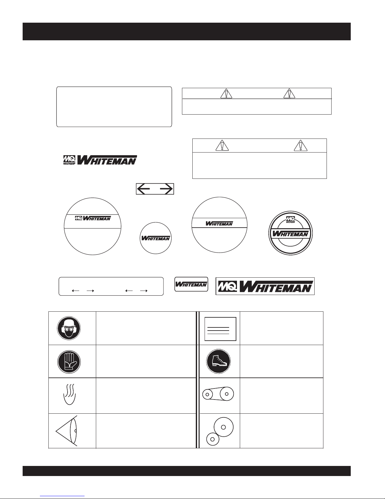
BA-SERIES TROWEL— OPERATION AND SAFETY DECALS
Machine Safety Decals
The BA-Series walk-behind trowel is equipped with a number of safety decals. These decals are provided for operator safety and
maintenance information. Figure 1 below illustrates these decals as they appear on the machine. Should any of these decals
become unreadable, replacements can be obtained from your dealer.
CAUTION
DO NOT LIFT MACHINERY BY GUARD
RING. MAY CAUSE DAMAGE TO
GUARD RING SHOCK MOUNTS
USE LIFT HANDLES ONLY
P/N 1261
P/N 1940
C
H
T
I
™
P
-
K
C
I
U
Q
BOISE, IDAHO USA
U. S. PATENT
XXXXXXX
C
O
N
C
R
E
I
T
F
E
P/N 1758
H
A
N
D
L
E
R
E
H
S
I
N
P/N 1736
I
C
U
K
Q
P
H
I
T
C
P/N 12405
WARNING!
INJURY COULD RESULT IF FINISHER IS LIFTED
WITHOUT PITCH HANDLE FIRMLY ENGAGE
P/N 20526
WARNING!
DO NOT OPERATE HANDLE UNTIL IT IS
SECURELY FASTENED TO POWER TROWEL
& INSTRUCTIONS HAVE BEEN READ
P/N 20527
E
T
E
F
R
L
C
N
O
C
FINISHER
B
O
I
S
E
P/N 1492
,
O
O
R
P
A
S
U
O
I
H
D
A
O
W
E
R
L
E
W
O
R
T
P/N 1848
PRELOAD TRIM INDICATOR
FINISH
J
COMBO
FINISH
P/N 1735
Symbol indicates that it is mandatory to wear
safety glasses, safety helmet and ear protection.
P/N 11247
Symbol indicates that it is mandatory to wear
gloves.
P/N 11247
Radiating heat symbol. Symbol indicates equipment
is hot.
P/N 11246
Symbol for examining or checking of the machine.
Mostly used for maintenance. Check lubrication
oil in gearbox.
P/N 11246
COMBO
B
(Part of decal kit 12620)
(Part of decal kit 12620)
(Part of decal kit 12620)
(Part of decal kit 12620)
Figure 1. BA-Series Trowel Decals
GENUINE
TROWEL
P/N 2938
METRIC
MADE IN USA
NAMEPLATE
P/N1499
CONTACT MULTIQUIP
SERVICE DEPT.
Symbol indicates that it is mandatory to
wear safety shoes, with extra protection
(steel toed).
P/N 11247
This is the symbol for belt drive.
P/N 11246
This is the symbol for gear drive.
P/N 11246
(Part of decal kit 12620)
(Part of decal kit 12620)
(Part of decal kit 12620)
PAGE 12 — BA-SERIES WALK-BEHIND TROWEL— PARTS & OPERATION MANUAL — REV. #3 (11/30/04)

Side View
BA-SERIES TROWEL— SPECIFICATIONS (TROWEL)
Figure 2. BA-Series Trowel Dimensions
)kooHgnitfiL(thgieH–A )mm2.678(ni5.43
)reveLtnemegagnEthgieH–B )mm2.440,1(ni1.14
htdiW–C
htgneL–D
gnitarepO–thgieW 3elbaTeeS
erusserPdnuoS bd79
noitarbiV s/m5.42(g5.2
retemaiDgniR )mc711(ni64
sedalBforebmuN 4ro3
)s/m(MPF–deepSpiTedalB )s/m5.7(mpf874,1
)enilosaG(MPR–rotoR 521ot06
)mc(.ni–htdiWhtaP )332(84
NOTE:
1. Sound pressure is a weighted measure. Measured at the
operators ear position while the walk-behind trowel is
operating at full throttle on concrete in a manner most often
experienced in “
may vary depending upon the condition of the concrete.
Hearing protection is always recommended.
normal
” circumstances. Sound pressure
2. The vibration level indicated is the maximum RMS (Root
Mean Square) value obtained at the handle grip while
operating the walk-behind trowel on curing concrete in a
manner most often experienced in “
Values were obtained from all three axes of motion. The
values shown represent the maximum RMS value from
these measurements.
snoitacificepSleworTseireS-AB.1elbaT
)mm4.861,1(0.64
)mm1.019,1(2.57
2
)
normal
” circumstances.
BA-SERIES WALK-BEHIND TROWEL — PARTS & OPERATION MANUAL — REV. #3 (11/30/04) — PAGE 13

BA-SERIES TROWEL— SPECIFICATIONS (ENGINES)
)rotoMcirtcelE&senignE(snoitacificepS.2elbaT
ledoM2AQ1K042XGADNOH2-52-HENIBORrotoMcirtcelE
elgniS,ekorts4delooc-riA
epyT
ekortSXeroB
tnemecalpsiDcc18.41cc13.51A/N
tuptuOxaM.M.P.R0063/.P.H0.8.M.P.R0004/.P.H5.8PH0.2
rotoMcirtcelE/enignE
leuFenilosaGdedaelnUenilosaGdedaelnUA/N
S
)HxWxL(noisnemiD
thgieWteNyrD
yticapaCknaTleuF
yticapaCliOebuLstnip3/1-2stnip2A/N
dohteMlortnoCdeep
dohteMgnitratStratSlioceRtratSlioceRA/N
egatloVtupnIA
VHO,rednilyC
)sretiL6(
epyT
/NA/N
latnoziroH,
enignEenilosaGtfahS
.ni03.2X.ni09.2
)mm85xmm37(
snollaG.S.U95.1.xorppA
thgiew-ylFlagufirtneC
.ni1.61X9.61x0.41
)mm014X034X553(
).gK52(sbl1.55).gK32(sbl7.05DBT
orppA
elgniS,ekorts4delooc-riA
latnoziroH,VHO,rednilyC
enignEenilosaGtfahS
.ni42.2X.ni59.2
)mm75xmm57(
snollaG.S.U95.1.x
)sretiL6(
epyTthgiew-ylFlagufirtneCA/N
.ni23.71X02.61x04.41
)mm044X214X663(
A/N
A/N
A/N
elgniSCAV032/511
esahP
DBT
)sthgieWleworT(snoitacificepS.3elbaT
LEDOMECRUOSREWOPTHGIEWGNITAREPOTHGIEWGNIPPIHS
H8-3-BadnoHPH8).gk701(.sbl732).gk031(.sbl682
SB8-4-BnottartSdnas
R7-4-BniboRPH5.7).gk701(.sbl732).gk031(.sbl782
MR7-4-BhctulClaunaM,nib
H8-4-BadnoHPH0.8).gk011(.sbl242).gk231(.sbl292
MH8-4-BhctulClaunaM,adno
PAGE 14 — BA-SERIES WALK-BEHIND TROWEL— PARTS & OPERATION MANUAL — REV. #3 (11/30/04)
ggirBPH8).gk301(.sbl822).gk621(.sbl872
oRPH5.7).gk701(.sbl732).gk031(.sbl782
HPH0.8).gk011(.sbl242).gk231(.sbl292

BA-SERIES TROWEL— GENERAL INFORMATION
BA-Series Walk-Behind Trowel Familiarization
This walk-behind trowel is designed for the
finishing
Take a walk around the trowel. Take notice of all the major
components (see Figure 3, pages 16 and 17) like the engine,
blades, quick pitch control, air cleaner, centrifugal stop switch
etc. Check that there is always oil in the engine.
Read
be found throughout this manual and on the trowel. Keep all
safety information in good, readable condition. Operators should
be well trained on the operation and maintenance of the trowel.
Before using your trowel, test it on a flat watered down section of
finished concrete that is free of any debris and other objects.
This trial test run will increase your confidence in using the trowel
and at the same time it will familiarize you with the trowel’s
controls. In addition you will understand how the trowel handles
under actual conditions.
Engines
This trowel is available with either an 8.0 HP HONDA, 8.5 HP
ROBIN, or a 8.0 HP Briggs and Stratton gasoline engine.
Refer to the engine owner’s manual for instructions regarding
the operation and maintenance of your engine. The engine
manual is included with your trowel at the time of shipment from
Whiteman. Please contact your nearest Multiquip Dealer for a
replacement should the original manual disappear.
Drive System
Power is transferred from the engine to the gearbox input shaft
via a V-belt or pulley drive system. The pulley engages using
either a centrifugal or manual clutch. See page 23.
Gearbox
The
to the
rotational speed of the trowel and is equipped with two shafts
(input and output).
Spider
of concrete slabs.
all the safety instructions carefully. Safety instructions will
gearbox
is located beneath the engine and transfers power
rotor
or
spider
assembly. The gearbox controls the
floating
and
Blades
The blades of the trowel finish the concrete as they are rotated
around the surface. Blades are classified as
inches wide),
wide). This trowel comes equipped with either
blades per rotor equally spaced in a radial pattern and
attached to vertical rotating shaft by means of a
assembly.
Centrifugal Stop Switch
In the event of a trowel runaway condition (operator releases
the handle), a
depending on which trowel you have, will stop the engine
and bring the trowel to a halt.
CAUTIONCAUTION
CAUTION
CAUTIONCAUTION
Moving the BA-Series Walk-Behind Trowel
This walk-behind trowel is designed to be moved and handled
in several ways. The easiest way to lift the trowel is to use the
auxiliary lifting tube
page 24, Figure 21. When using the auxiliary tube, always use
two persons
Some models have a
chain can be attached to the lifting bale, allowing a forklift or
crane to lift the trowel up onto a slab of concrete. Use a lifting
device of adequate lifting capacity to lift the trowel.
Training
For proper training, please use the “TRAINING CHECKLIST”
located in the front of this manual (Page 6). This checklist will
provide an outline for an experienced operator to provide training
to a new operator.
combination
float
(10 or 8 inches wide), and finish (6 inches
three
or four
spider
centrifugal stop switch
NEVER attempt to
ALWAYS get the assistance of another
person to help lift the trowel or use a crane or
lifting device to move the trowel.
that is attached to the main handle. See
to lift the trowel.
lifting bale
(option) installed. A strap or
or
manual clutch
lift
the trowel by yourself.
(8
The vertical output shaft of the gearbox connects to a cast hub
spider
called the
outward that are used for attachment of blades or other
accessories. Remember as the gearbox output shaft rotates so
does the spider assembly.
BA-SERIES WALK-BEHIND TROWEL — PARTS & OPERATION MANUAL — REV. #3 (11/30/04) — PAGE 15
. The spider has either 3 or 4 arms that extend

BA-SERIES TROWEL— CONTROLS AND COMPONENTS
FINISH
COMBO
PRELOADTRIM
INDICATOR
FINISH
COMBO
QUICK PITCH ™
HANDLE
W
4
3
5
6
2
1
7
8
O
B
R
M
O
C
TO
A
C
I
B
D
N
I
H
IS
M
IN
I
F
R
T
O
B
D
M
O
A
C
O
L
E
J
R
P
H
IS
IN
F
13
9
4
5
3
2
11
6
20
Figure 3. BA-Series Walk-Behind Trowels
10
16
17
15
W
12
8
7
STANDARD
HANDLE
13
14
18
PAGE 16 — BA-SERIES WALK-BEHIND TROWEL— PARTS & OPERATION MANUAL — REV. #3 (11/30/04)

BA-SERIES TROWEL— CONTROLS AND COMPONENTS
Figures 3 shows the location of the basic controls or components,
for the BA-Series trowel. Listed below is a brief explanation of
each control or component
1. Quick Pitch™ Control Handle – To adjust the pitch of
the blades, grasp the handle then squeeze and either move
the handle forward or backward to achieve the desired
blade pitch.
2. Handlebar Adjuster – Change the angle/height of the
handle bars by loosening star wheel, adjust handlebars to
desired location, tighten starwheel firmly to hold handlebars
in that position.
3. Hand Grip/Handle Bar – When operating the trowel, place
both hands on each grip to maneuver the trowel. Replace
hand grips when they become worn or damaged.
4. Throttle Control Grip – Controls the speed of the engine.
Rotate the hand grip away from the operator to increase
engine speed (high), toward the operator to decrease
engine speed (low).
5. Throttle – Controls engine speed when throttle control
grip is rotated.
15. Engine – This trowel uses Honda, Robin and Briggs and
Stratton type gasoline engines.
16. Trowel Arm – NEVER operate the trowel with a bent,
broken or out of adjustment trowel arm. If the blades show
uneven wear patterns or some blades wear out faster than
others, the trowel arm may need to be adjusted. Use the
trowel arm adjustment tool P/N 1817 to adjust the trowel
arms.
17. Blades – This trowel is equipped with combination blades.
These blades are versatile and should take care of most
troweling needs. In addition float discs can be attached to
the trowel arms that will allow the trowel to float on "wet"
concrete.
18. V-Belt Cover – Remove this cover to gain access to the Vbelt. NEVER operate the trowel with this cover removed.
20. Stabilizer Ring – Reduces trowel arm vibration. Helps
stabilize trowel arm.
6. Hand Grip/Handle Bar – When operating the trowel, place
both hands on each grip to maneuver the trowel. Replace
hand grips when they become worn or damaged.
7. Centrifugal Kill Switch – In the event the operator loses
control of the trowel, this switch will shut-down the engine.
8. Auxiliary Lifting Tube - Use this tube to lift the trowel onto
a slab. Tube is to be inserted into socket located in front of
the gearbox.
9. Weights – The trowel may be equipped with two 10 lbs.
weights. The weights may be removed to reduce the
operating weight of the trowel.
10. Trowel Lifting Point – Insert the auxiliary lifting tube here.
See Figure 21.
11. Pitch Control (standard models) - Turn this "Star Wheel"
clockwise for increase blade pitch, and counter-clockwise
for decrease blade pitch.
12. Clutch Lever - Clutch engagement lever. When this lever
is engaged, the blades will begin to rotate. May be used
with either Quick Pitch™ or Standard handle.
13. Main Tube - When disassembling components inside the
tube exercise extreme CAUTION! Tube is spring-loaded,
severe injury could result if not disassembled correctly.
14. Guard Ring- NEVER! put hands or feet inside guard ring.
BA-SERIES WALK-BEHIND TROWEL — PARTS & OPERATION MANUAL — REV. #3 (11/30/04) — PAGE 17

HONDA engine shown.
BA-SERIES TROWEL— BASIC ENGINE
Figure 4. Engine Controls and Components
INITIAL SERVICING
The engine (Figure 4) must be checked for proper lubrication and
filled with fuel prior to operation. Refer to the manufacturers engine
manual for instructions & details of operation and servicing. The
engine shown above is a HONDA engine, operation for other
types of engines may vary somewhat.
1. Fuel Filler Cap – Remove this cap to add unleaded
gasoline to the fuel tank. Make sure cap is tightened
securely. DO NOT over fill.
5. Fuel Valve Lever – OPEN to let fuel flow, CLOSE to stop
the flow of fuel.
6. Choke Lever – Used in the starting of a cold engine, or in
cold weather conditions. The choke enriches the fuel
mixture.
7. Air Cleaner – Prevents dirt and other debris from entering
the fuel system. Remove wing-nut on top of air filter
cannister to gain access to filter element.
DANGER
Adding fuel to the tank should be done only when
the engine is stopped and has had an opportunity to
cool down. In the event of a fuel spill, DO NOT attempt to start the
engine until the fuel residue has been completely wiped up, and the
area surrounding the engine is dry.
2. Throttle Lever – Used to adjust engine RPM speed (lever
SLOW
advanced forward
FAST
).
, lever back toward operator
8. Spark Plug – Provides spark to the ignition system. Set
spark plug gap to 0.6 - 0.7 mm (0.028 - 0.031 inch) Clean
spark plug once a week.
9. Muffler – Used to reduce noise and emissions.
NOTE
Operating the engine without an air filter,
with a damaged air filter, or a filter in need of
replacement will allow dirt to enter the
engine, causing rapid engine wear.
WARNING
3. Engine ON/OFF Switch – ON position permits engine
starting, OFF position stops engine operations.
4. Recoil Starter (pull rope) – Manual-starting method. Pull
the starter grip until resistance is felt, then pull briskly and
smoothly.
PAGE 18 — BA-SERIES WALK-BEHIND TROWEL— PARTS & OPERATION MANUAL — REV. #3 (11/30/04)
Engine components can generate extreme heat.
To prevent burns, DO NOT touch these areas
while the engine is running or immediately after operating. NEVER
operate the engine with the muffler removed.
10. Fuel Tank – Holds unleaded gasoline. For additional
information refer to engine owner's manual.

BA-SERIES TROWEL — ASSEMBLY AND INSTALLATION
Assembly and Installation
Before the trowel can be put into operation there are some
components that must be installed before the trowel can be used.
This section provided general instructions on how to install those
components. Instruction sheet P/N 20485 provides further details
for the handle assembly.
Handle Tube Installation (All Models)
1. Install the
handle tube
to the gearbox as shown in (Figure 5).
The mounting hardware should be contained in the shipping
container.
Figure 5. Handle Tube Installation
2. On Quick-Pitch™ models, pivot the
T-handle
back
(full pitch) (Figure 6). This will relax the spring inside the
handle tube. On either model, spread the handle bar ends
just enough to engage the teeth on the handle tube. Attach
the hand wheel assembly, position handlebar to desired
location, and tighten hand wheel firmly.
CAUTIONCAUTION
CAUTION
CAUTIONCAUTION
The Quick-Pitch™ handle is spring loaded,
personal injury or damage could result from
improper handling or installation. Be careful
when installing this component.
NOTE
Figure 6. Handlebar Installation
Throttle Cable Installation (Honda and Robin Engines)
1. Set the
throttle
(Figure 7) to the idle position by rotating
the grip toward the operator and away from the engine.
Figure 7. Throttle
2. Feed the throttle cable through the cable housing. Make sure
the throttle indicator is on 1".
3. Connect the throttle cable to the engine. (Figure 8),
and (Figure 9),
Robin
. There should be a piece of wire
Honda
installed on the trowel to show where to route the throttle
cable. When connecting the cable housing, make sure that
no more than
1/4" (6.4mm)
of the cable housing protrudes
past the housing clamp on the engine.
THROTTLE
CABLE END
ENGINE
THROTTLE
LEVER
SWIVEL STOP
SCREW
Considerable force may be required when
moving the Quick-Pitch™ T-handle
forward or backward.
BA-SERIES WALK-BEHIND TROWEL — PARTS & OPERATION MANUAL — REV. #3 (11/30/04) — PAGE 19
CABLE
HOUSING
CLAMP
CABLE HOUSING
Figure 8. Throttle Cable Connection (HONDA)

BA-SERIES TROWEL — ASSEMBLY AND INSTALLATION
Figure 9. Throttle Cable Connection (ROBIN)
4. Tighten cable clamp screw and swivel stop screw.
5. After the cable has been installed on the engine, adjust
and tighten operator position of the handle to lock the
throttle cable at the proper length.
6. Adjust cable tension by rotating the barrel adjuster. (Figure
10)
BARREL ADJUSTER
Figure 10. Barrel Adjuster
7. These are general instructions. Installation of the throttle
cable may vary for different engine configurations. Please
look for more detailed instructions inside the box containing
the handle. These more detailed instructions should provide
adequate guidance for installing.
Handle Height Adjustment
If handle height adjustment is desired, a handle wedge kit can be
purchased for your trowel by ordering P/N 2576 from your Multiquip
dealer. These wedges are placed between the handle and the
gearbox to adjust the operating height of the handle. This kit
comes complete with wedges, new bolts and installation
instructions. This will move your operating handle position up or
down approximately 3” (76mm).
Pitch Cable Installation
1. Expose the pitch cable to maximum by adjusting the handle
pitch to the "no pitch" position. On the standard model turn
the pitch control counter-clockwise, (Figure 12). On the
Quick-Pitch™ model, pivot the pitch handle forward or no
pitch, (Figure 13).
Figure 11. Engine Kill Wire Connection
Figure 12. "No Pitch" Position (Standard)
Safety Kill Wire
Locate the
and connect it to the
switch to insure proper operation.
RED
wire protruding from the handle tube (Figure11)
RED
tail wire on the engine. Test the kill
PAGE 20 — BA-SERIES WALK-BEHIND TROWEL— PARTS & OPERATION MANUAL — REV. #3 (11/30/04)
Figure 13. "No Pitch" Position (Quick-Pitch™)

BA-SERIES TROWEL — ASSEMBLY AND INSTALLATION
Pre-load Adjustment (Quick-Pitch™ Models Only)
2. Lock the spring in the compressed position, by releasing
the blade pitch adjustment trigger, (Quick-Pitch™ model).
3. Remove one brass set nut from the blade pitch cable end
as shown in (Figure 14).
4. Thread the second brass set nut towards the cable as far
as possible.
1. After the Quick-Pitch™ handle has been installed on the
trowel, spring pre-load adjustment will be required.
2. Locate the adjustment screw on the underside of the handle
tube (Figure 16).
Figure 14. Blade Pitch Cable
5. Insert the cable end through the yoke eyelet (Figure 15)
Tighten the first brass set nut by hand to remove all the
slack from the cable.
6 Using a wrench, tighten the second brass set nut up against
the yoke boss. This will lock the cable in place.
7. Use a wrench and finish tightening the first brass set nut up
against the yoke boss.
3. A
assist the user in the adjustment of the spring.
4. Align the
COMBO
Walk-Behind trowel.
5. Test the pitch control operation and adjust if necessary.
YOKE
THREAD CABLE END
THROUGH YOKE EYELET
Figure 16. Pre-load Adjustment
decal
has been placed on the side of the handle tube to
arrow
on the adjustment screw with the letter "B"
on the
decal
. The letter "B" stands for BA-Series
TIGHTEN SECOND
BRASS SET NUT
AGAINST YOKE BOSS
USE A WRENCH TO
TIGHTEN FIRST BRASS
SET NUT AGAINST YOKE BOSS
Figure 15. Cable Yoke Attachment
BA-SERIES WALK-BEHIND TROWEL — PARTS & OPERATION MANUAL — REV. #3 (11/30/04) — PAGE 21

CAUTIONCAUTION
CAUTION
CAUTIONCAUTION
NEVER operate the trowel
in a confined area or
enclosed area structure
that does not provide ample
free flow of air
ALWAYS wear approved eye and hearing
protection before operating the trowel.
NEVER place hands or feet inside the guard
rings while the engine is running. ALWAYS shut
the engine down before performing any kind
of maintenance service on the trowel.
.
BA-SERIES TROWEL— PRE-INSPECTION
Figure 17. Engine Oil Dipstick (Removal)
3. Insert and remove the dipstick without screwing it into the filler
neck. Check the oil level shown on the dipstick.
4. If the oil level is low (Figure 18), fill to the edge of the oil filler
hole with the recommended oil type (Table 4). Maximum oil
capacity is 400 cc.
It is recommended that the trowel's
the engine after every use. Doing this will verify that the switch is
working properly and presents no danger to the operator.
Before Starting
1. Read safety instructions at the beginning of manual.
trowel
2. Clean the
engine cooling air inlet, carburetor and air cleaner.
3. Check the air filter for dirt and dust. If air filter is dirty, replace
air filter with a new one as required.
4. Check carburetor for external dirt and dust. Clean with dry
compressed air.
5. Check fastening nuts and bolts for tightness.
Engine Oil Check
1. To check the engine oil level, place the trowel on secure level
ground with the engine stopped.
, removing dirt and dust, particularly the
kill switch
be used to stop
NOTE
Reference manufacturer engine manual for
specific servicing instructions.
Figure 18. Engine Oil Dipstick (Oil Level)
epyTliO.4elbaT
nosaeS erutarepmeT epyTliO
remmuS rehgiHroC°52 03-W01EAS
2. Remove the filler dipstick from the engine oil filler hole
(Figure 17) and wipe it clean.
PAGE 22 — BA-SERIES WALK-BEHIND TROWEL— PARTS & OPERATION MANUAL — REV. #3 (11/30/04)
llaF/gnirpS C°01~C°52 02/03-W01EAS
retniW rewoLroC°0 01-W01EAS

BA-SERIES TROWEL— PRE-INSPECTION
Blade Check
Explosive Fuel
Fuel Check
Motor fuels are highly flammable and can be dangerous if
mishandled. DO NOT smoke while refueling. DO NOT attempt
to refuel the trowel if the engine is
hot! or running
.
1. Remove the gasoline cap located on top of fuel tank.
2. Visually inspect to see if fuel level is low. If fuel is low, replenish
with unleaded fuel.
3. When refueling, be sure to use a strainer for filtration. DO
NOT top-off fuel. Wipe up any spilled fuel.
Gearbox Oil
Check for worn or damaged blades. Check to see if one blade is
worn out while the others look new. If this is the case there could
be a blade pitch problem. Refer to the maintenance section of
this manual for blade pitch adjustment procedure. Replace any
worn blades.
CONTROLS
Safety Kill Switches
This trowel has been equipped with a safety kill switch or a hand
operated clutch. Safety kill switches or hand clutches should be
tested every time the engine is started.
NOTE
NEVER!
disable or disconnect the kill switch.
It is provided for operator safety. Injury may
result if it is disable, disconnected or
improperly maintained.
1. Determine if the
gearbox
oil is low by removing the oil
plug located on the side of the gearbox. This plug will be
check
marked by the "
" decal. See Figure 19. The correct
level of the lubrication oil should be to the bottom of the fill
plug.
Centrifugal Type Kill Switch
The switching mechanism of this switch (Figure 20) should
operate freely and should
the switch in the OFF position, the engine should not start or run.
GEARBOX
The purpose of this switch is to stop the engine in a runaway
situation, (i.e.-the operator releasing the handle during operation).
OIL SIGHT/
FILL PLUG
DRAIN
PLUG
Figure 19. Gearbox
2. If oil does not reach the middle of the
sight glass
type ISO 680 (Whiteman P/N 10139) gearbox lubricant oil
until the oil level reaches the middle of the sight glass.
V-belt Check
A worn or damaged V-belt can adversely affect the performance
of the trowel. If a V-belt is defective or worn simply replace the Vbelt as outlined in the maintenance section of this manual.
fill with
Hand Clutch
Some finisher models are equipped with a
clutch
unit automatically stops rotating when the clutch lever is released.
DO NOT let the machine sit unused with the engine at high speed
for an extended period of time. It will cause premature belt wear
or may destroy the belt. Always set the engine speed to idle when
the hand clutch is disengaged.
always
be kept in this condition. With
Figure 20. Centrifugal Kill Switch
hand operated
. These units are not equipped with a safety kill switch. The
BA-SERIES WALK-BEHIND TROWEL — PARTS & OPERATION MANUAL — REV. #3 (11/30/04) — PAGE 23

BA-SERIES TROWEL — INITIAL START-UP
CAUTIONCAUTION
CAUTION
CAUTIONCAUTION
The trowel is
around. Use proper heavy lifting procedures
and DO NOT
rings.
Lifting the Trowel Onto a Slab.
Auxiliary Lifting Tube
Remove the auxiliary lifting tube located on top of the main handle.
Insert the tube into the socket located on the opposite side of the
gearbox (Figure 21) from the handle.
Make sure that the hole in the tube engages with the pin in the
socket. With one person lifting from the main handle, and another
lifting from the auxiliary lifting tube pick up the machine to move
onto a slab.
heavy
and
awkward
lift the trowel by the guard
to move
This section is intended to assist the operator with the initial
start-up of the walk-behind trowel. It is extremely important that
this section be read carefully before attempting to use the trowel
in the field.
DO NOT use your trowel until this section is thoroughly
understood.
CAUTIONCAUTION
CAUTION
CAUTIONCAUTION
Starting the Engine (
1. Place the engine
position.
DO NOT attempt to operate the trowel until
the Safety, General Information and
Inspection sections of this manual have
been read and thoroughly understood.
Depending on engine manufacturer,
operating steps may vary. See engine
manufactures operating manual. The
following start-up procedure makes
reference to a HONDA 13 HP Engine
(Manual Start).
HONDA
fuel valve lever
engine)
(Figure 22) to the "ON"
Figure 21. Lifting the Trowel
CAUTIONCAUTION
CAUTION
CAUTIONCAUTION
The trowel must be stabilized by the person
carrying the
If it is not stabilized properly the handle may
swing around and
damage to the trowel and bodily injury.
Lifting Bale (Option)
The lift bale is optional on new trowels. It provides an optimal lift
point for moving the trowel.
lift a trowel up onto a building with a crane. See “
Equipment
Using a
recommended, and is perfectly safe for the machine. Extra care
should be taken when lifting the machine off the ground, though.
Serious damage to the machine or personal injury could be
caused by dropping a trowel.
” section in this manual for ordering information.
crane
to move a machine with a lift bale is highly
PAGE 24 — BA-SERIES WALK-BEHIND TROWEL— PARTS & OPERATION MANUAL — REV. #3 (11/30/04)
operator’s handle
flip
the trowel, thus causing
Lift bales or forklift
(Figure 21).
2. Rotate the
can be used to
Optional
Figure 22. Engine Fuel Valve Lever
throttle
Figure 23. Throttle (Idle Position)
(Figure 23) to the "idle" position.

BA-SERIES TROWEL — INITIAL START-UP
3. Place the
position. For models that use this feature.
CAUTIONCAUTION
CAUTION
CAUTIONCAUTION
4. Place the
centrifugal kill switch
NEVER disable or disconnect the centrifugal
kill switch. It is provided for the operators’
safety and injury may result if it is disabled,
disconnected or improperly maintained.
Figure 24. Centrifugal Kill Switch
Choke Lever
(Figure 25) in the "
(Figure 24) in the "ON"
OPEN
" position
Figure 26. Starter Grip
6. If the engine has started, slowly return the choke lever
(Figure 25) to the
started repeat steps 1 through 5.
Before the trowel is placed into operation, run the engine for
7.
several minutes. Check for fuel leaks, and noises that would
associate with a loose guard ring and/or covers.
8. To begin troweling, rotate the throttle (Figure 27) toward the
RUN
" position.
"
CLOSED
position. If the engine has not
Figure 27. Throttle (Run Position)
Figure 25. Engine Choke Lever
5. Grasp the starter grip (Figure 26) and slowly pull it out. The
resistance becomes the hardest at a certain position, corresponding to the compression point. Pull the starter grip briskly
and smoothly for starting.
BA-SERIES WALK-BEHIND TROWEL — PARTS & OPERATION MANUAL — REV. #3 (11/30/04) — PAGE 25

BA-SERIES TROWEL — OPERATION
The following steps are intended as a basic guide to machine
operation, and are not to be considered a complete guide to
concrete finishing. We suggest that all operators (experienced
and novice) read “
Concrete Institute, Detroit, Michigan
section of this manual for more information.
Slabs on Grade
” published by the
. Read the “Training”
American
Pitching The Blades
Quick Pitch Handle
1. To pitch the blades upwards using the
T-handle
and pull the
the
, (Figure 28) simply squeeze the trigger lock
T-handle
T-handle
towards the engine will cause the blades
towards the operator. Pushing
"Quick-Pitch
Maneuvering the Trowel
Get into the operator’s position behind the handle. With a
1.
secure foothold and a firm grasp on the handles slowly
increase the engine speed until the desired blade speed is
obtained.
If your trowel has a
speed with the throttle, then pull on the hand clutch lever to
start the blades turning. Adjust the blade speed after the hand
™"
clutch is fully engaged.
to lay flat.
hand clutch (Figure 30)
, set your engine
Figure 30. Hand Clutch Lever
Figure 28. Quick-Pitch™ T- Handle
Standard Handle
1. To pitch the blades upwards using the "
(Figure29) simply turn the
star-wheel
Standard
clockwise. Turning the
" handle,
star wheel counter clockwise will cause the blades to lay flat.
2.
To maneuver the trowel, gently lift up on or press down on the
main trowel handle. To move the machine to the operator’s
lift up
left,
down
3. The best method for finishing concrete is to slowly walk
backwards (Figure 31) with the trowel, guiding the trowel
from side to side. This will cover all footprints on wet concrete.
4. Remember that if you let go of the trowel, just step away and
let the trowel come to a complete stop before trying to recover
the trowel.
on the handle, to move machine to the right,
on the handle.
push
Figure 29. Standard Handle
PAGE 26 — BA-SERIES WALK-BEHIND TROWEL— PARTS & OPERATION MANUAL — REV. #3 (11/30/04)

BA-SERIES TROWEL — OPERATION
Figure 32 below illustrates a typical walk-behind trowel
application. Practice maneuvering the trowel. The trick is to let
the trowel do the work.
Continue to practice maneuvering the trowel. Try to practice as if
you were finishing a slab of concrete. Practice edging and
covering a large area. Remember a good finishing technique is
to work backwards. Be careful when moving backwards so that
hazards can be avoided. The best way to get accustomed to the
trowel is repeated use.
CAUTIONCAUTION
CAUTION
CAUTIONCAUTION
NEVER place your
guard rings while starting or operating this
equipment.
BA-SERIES WALK-BEHIND TROWEL — PARTS & OPERATION MANUAL — REV. #3 (11/30/04) — PAGE 27
feet
Figure 31. Maneuvering The Trowel
CAUTIONCAUTION
CAUTION
CAUTIONCAUTION
or
hands
inside the
ALWAYS keep clear of
parts while operating this equipment.
rotating
or
moving

BA-SERIES TROWEL — OPTIONS
Blades
NOTE
Blades should be changed when they fail to
Specification and part number
finish concrete in a satisfactory manner.
are subject to change without
notice.
Blades are a vital part of finishing concrete. This trowel, or
finisher
built to stringent quality standards out of the finest trowel steel. If
you need replacement blades, consult your parts list in this
manual for part numbers and order them from your Multiquip parts
dealer or importer.
Combo Blades
This trowel was equipped with combination
32) blades as original equipment. These blades have been
designed for optimum performance in both the floating and
finishing operations. These blades are versatile and should take
care of most troweling needs.
, has been designed to finish concrete and the blades are
float/finish
(Figure
Clip-On Float Blades (Optional)
These blades will clip (Figure 34) on to an existing installed blade,
allowing your finisher to float on “wet” concrete so that the
troweling operation can begin as early as possible. They are
easily removable, so that after the floating operation, when the
concrete is sufficiently cured, they can be removed to expose the
finish blades for continued troweling.
Float Discs (Optional)
These round discs (Figure 35) attach to the spiders and allow the
machine to “float” on “wet” concrete. The disc design allows early
floating and easy movement from wet to dry areas. They are also
very effective in embedding large aggregates and surface
hardeners.
Figure 34. Clip-On Float Blade
Figure 32. Combination Blade
Finish Blades (Optional)
These blades (Figure 33) have been specifically designed for
finish operations with this trowel. They will provide a premium
surface finishing capability from your trowel. They should only be
used after the concrete has set to the point where the trowel does
not sink into the concrete when placed on it.
Figure 33. Finish Blade
PAGE 28 — BA-SERIES WALK-BEHIND TROWEL— PARTS & OPERATION MANUAL — REV. #3 (11/30/04)
Figure 35. Float Disk

BA-SERIES TROWEL — OPTIONS
Grinding Attachments
Available grinding attachments are used for grinding surface
imperfections or joints. These attachments allow greater utilization
of your trowel. Figure 36 illustrates a typical grinding disk assembly,
complete with hub and stone mounting plate.
Trowel Arm Adjustment Tool
If blades show uneven wear patterns or some tend to wear out
faster than others, the trowel arms may need to be adjusted.
Whiteman makes a special tool (Figure 38) that will adjust all of
the trowel arms consistently. The Trowel Arm Fixture P/N is 1817.
Figure 36. Grinding Disk
Lifting Bale
Figure 38. Trowel Arm Adjustment Fixture
There is a heavy duty, center balance type lifting bale (Figure 37)
made specifically for your trowel. These bales are ideal for lifting
and transporting your trowel. They are designed to lift the finisher
and balance it on it’s center of gravity, providing great stability
while lifting. This option is not available on electric trowel models.
Figure 37. Lifting Bale
BA-SERIES WALK-BEHIND TROWEL — PARTS & OPERATION MANUAL — REV. #3 (11/30/04) — PAGE 29

BA-SERIES TROWEL — MAINTENANCE
NOTE
Trowel Arm Adjustment Procedure
See the engine manual supplied with your
machine for appropriate engine maintenance
schedule and troubleshooting guide for
problems.
At the front of the book (Page 7) there is a “
Checklist
basis.
CAUTION!CAUTION!
CAUTION!
CAUTION!CAUTION!
ALWAYS allow the engine to cool before
servicing. NEVER attempt any maintenance work
on a
MAINTENANCE SCHEDULE
Daily (8-10 Hours)
1. Check the oil level in the engine crankcase and gear box,
2. Check V-belt.
Weekly (50-60 Hours)
1. Relube arms, thrust collar and clutch.
”. Make copies of this checklist and use it on a daily
hot!
engine.
fill as necessary.
Daily Pre-Operation
level
, clean area to test the trowel prior to and after is essential.
A
Any unlevel
will give an incorrect perception of adjustment. Ideally, a 5 x 5"
three-quarter inch thick
1. To determine which blades need adjustment, place the
trowel in the test area (three-quarter inch thick plate) and look
for the following conditions:
■
■
Figure 39 below illustrates a "
trowel arms
touching (0.10" max. clearance) lower wear plate. All alignment
bolts should be spaced the same distance from the lower wear
plate.
NOTE
The following procedure should be followed
to adjust trowel arms when it becomes
apparent that the trowel is finishing poorly or
in need of routine maintenance.
spots
in the floor or debris under the trowel blades
flat
steel plate should be used for testing.
Pitch the blades as flat as possible and look at the
adjustment bolts
with the
that one of them is not making contact, some adjustment
will be necessary.
Is the machine wearing out blades unevenly (i.e. one
blade is completely worn out while the others look new)?
lower wear plate
". Check to see that adjustment bolt is barely
. They should all barely make contact
on the spider. If you can see
worn spider bushings or bent
2. Replace blades if necessary.
3. Check and clean or replace the engine air filter as
necessary.
4. Replace engine oil and filter as necessary, see engine
manual.
Monthly (200-300 Hours)
1. Remove, clean, reinstall and relube the arms and thrust
collar. Adjust the blade arms.
2. Remove, clean, reinstall clutch.
Yearly (2000-2500 Hours)
1. Check and replace if necessary the arm bushings, thrust
collar bushings and shaft seals.
2. Check pitch control cables for wear.
3. Adjust blade speed.
PAGE 30 — BA-SERIES WALK-BEHIND TROWEL— PARTS & OPERATION MANUAL — REV. #3 (11/30/04)
Figure 40 below illustrates the "
plate (as shipped from the factory).
Figure 39. Worn Spider Plate
correct alignment
Figure 40. Correct Spider Plate Alignment
" for a spider

BA-SERIES TROWEL — MAINTENANCE
2. Start engine, and bring trowel blades up to full speed and look
for the following conditions:
■
Does the trowel have a perceived rolling or bouncing
motion when in use?
■
Look at the trowel while it is running, does the guard
ring “rock up and down” relative to the ground?
Spider Removal
1. Once it is determined that an adjustment is required, remove
the spider assembly from the gearbox shaft as follows:
a. Locate the cone point square head set screw (Figure 41)
and attached jam nut found on the side of the spider
assembly.
b. Loosen the jam nut and cone point square head set
c. If the trowel is equipped with an outer stabilizer ring
screw, and carefully lift the
of the spider assembly. A slight tap with a rubber mallet
may be necessary to dislodge the spider from the main
shaft of the gearbox.
(Figure 42), remove the four bolts at the end of each
spider arm.
upper trowel assembly
off
Figure 42. Stabilizer Ring
d. Examine stabilizer ring for out of round or bends. If ring
is damaged, replace ring. If ring is found to be correct with
no damage, set aside.
Trowel Arm Removal
1. Each trowel arm is held in place at the spider plate by a hex
head bolt (zerk grease fitting) and a roll pin. Remove both the
hex head bolt and the roll pin (Figure 43) from the spider
plate.
2. Remove the trowel arm from the spider plate.
Figure 41. Spider/Gearbox Removal
BA-SERIES WALK-BEHIND TROWEL — PARTS & OPERATION MANUAL — REV. #3 (11/30/04) — PAGE 31
Figure 43. Removing Roll Pin
and Zerk Grease Fitting

BA-SERIES TROWEL — MAINTENANCE
3. Should the trowel arm inserts (bronze bushing ) come out
with the trowel arm, remove the bushing from the trowel arm
and set aside in a safe place. If the bushing is retained inside
the spider plate, carefully remove the bushing.
4. Examine the bronze trowel arm bushing insert (Figure 44),
clean if necessary. Replace bushing if out of round or worn.
Trowel Arm Flatness Test
1. Using a piece of 3/4 inch thick steel plate or any surface which
true
is
flatness.
2. Check each of the six sides of the trowel arm (hex section
only) using a ten thousands of an inch (max.) feeler gauge
(Figure 46) between the flat of the trowel arm and an
tremely flat
Figure 44. Bronze Bushings
Trowel Blade Removal
1. Remove the trowel blades from the trowel arm by removing
the three hex head bolts (Figure 45) from the trowel arm. Set
blades aside.
and
flat
, check all
test surface.
six sides
of each trowel arm for
ex
-
Figure 45. Trowel Blades
2.
Wire brush
trowel arm. Repeat this for the remaining three arms.
any build-up of concrete from all six sides of the
Figure 46. Trowel Arm Flatness Test
3. If the trowel arm is found to be
trowel arm. A bent trowel will not allow the trowel to operate
in a smooth fluid rotation.
4. Next, check each of the six sides of the round machined shaft
section of the trowel arm. Each section should have the
clearance
test surface.
between the round of the trowel arm shaft and the
NOTE
uneven
or
bent
, replace the
same
Trowel arms can be damaged by rough
handling or by striking exposed plumbing or
forms while in operation.
ALWAYS
look-out
for objects which might cause damage to the
trowel arms.
PAGE 32 — BA-SERIES WALK-BEHIND TROWEL— PARTS & OPERATION MANUAL — REV. #3 (11/30/04)

BA-SERIES TROWEL — MAINTENANCE
Trowel Arm Adjustment
Shown in Figure 47 is the adjustment fixture with a trowel arm
inserted. As each trowel arm is locked into the fixture, the arm bolt
is adjusted to where it contacts a stop on the fixture. This will
consistently adjust all of the trowel arms, keeping the finisher as
flat and evenly pitched as possible.
1. Locate the trowel arm adjustment tool P/N 1817. Set the
adjustment tool for a clock-wise blade rotation, meaning the
fixture arm is in the "UP" position.
3. Un-screw the locking bolts on the adjustment tool, and place
the trowel arm into the adjustment fixture channel as shown
in Figure 48. A
holes on the trowel arm. Make sure to align the trowel
adjustment bolt with the fixture adjustment bolt.
4. Using an allen wrench, tighten the locking bolts on the
adjustment tool and securely lock the trowel arm in place.
5. Loosen the locking nut on the trowel arm lever, then turn the
trowel arm adjusting bolt until it barely touches (.010") the
adjusting bolt on the fixture.
6. After the correct adjustment has been made, tighten lock nut
on trowel arm lever to lock in place.
7. Loosen locking bolts on adjustment fixture, and remove
trowel arm from fixture.
8. Repeat steps 2-7 for the remaining trowel arms.
Re-Assembly
1. Clean and examine the upper/lower wear plates and thrust
collar. Examine the entire spider assembly. Wire brush any
concrete or rust build-up. If any of the spider components are
found to be damaged or out of round, replace them.
thin shim
may be required to cover the blade
2. Make sure that the bronze trowel arm bushing is not damage
3. Reinstall bronze bushing onto trowel arm.
4. Repeat steps 2 -3 for each trowel arm.
5. Make sure that the spring tensioner is in the correct position
6. Insert all trowel arms with levers into spider plate (with bronze
7. Lock trowel arms in place by tightening the hex head zerk
Figure 47. Trowel Arm Adjustment Tool
2. Trowels manufactured prior to June of 1982 require that the
distance from the end of the adjusting bolt and the fixture arm
must be 7/8" (Figure 48). Conversely, trowels manufactured
after June of 1982 require that the distance from the end of
the adjusting bolt and the fixture arm must be 1/2".
8. Re-install the blades back onto the trowel arms.
9. Install stabilizer ring onto spider assembly.
10. Reinstall lower wear plate,
or out of round. Clean the bushing if necessary. If the bronze
bushing is damage or worn, replace it.
to exert tension on the trowel arm.
bushing already installed) using care to align grease hole on
bronze bushing with grease hole fitting on spider plate.
grease fitting and jam nut.
thrust collar
in the
ring
the spider shaft. Make sure that there is little or no lateral
movement between the thrust collar and the spider shaft.
reverse order
that they were dis-assembled onto
and
upper wear
BA-SERIES WALK-BEHIND TROWEL — PARTS & OPERATION MANUAL — REV. #3 (11/30/04) — PAGE 33

BA-SERIES TROWEL — MAINTENANCE
11. Carefully lift
the upper trowel assembly
, line up the key-
way on gear box main shaft and insert into spider assembly.
12. Reinstall square head cone point into spider plate and
tighten in place. Tighten jam nut. Use care in making sure
point of set screw engages groove in gear box main shaft.
Hand Clutch Adjustment
Some trowels are equipped with a hand-operated clutch instead
of an automatic centrifugal clutch. Two types of hand clutches
have been installed. Both are belt-tightener type clutches. They
operate by removing
power from the engine to the gearbox.
13. Lubricate all grease points (zerk fittings) with premium
Lithum 12"
"
based grease, conforming to NLG1 Grade #2
There are two reasons to adjust the hand clutch: 1) operator
comfort; 2) initial belt stretch and break-in.
consistency.
Testing
1. Place trowel in test area, start engine and test trowel for
smoothness.
The easiest and most simple adjustment is to adjust the clutch
cable housing using the adjustment nut (Figure 48) located on the
clutch lever. Rotating the nut provides either more or less
(depending upon the direction of rotation) clutch engagement.
2. If trowel bounces has excessive vibration or does not run
smoothly repeat alignment procedure.
Changing a Blade
Whiteman recommends that
same time
. The machine may wobble or bounce if only some of
all the blades be changed at the
the blades are changed at one time.
slack
in the V-belt which then transmits
Figure 48. Hand Clutch Adjustment
1. Place the machine on a flat, level surface. Adjust the blade
pitch control to make the blades as flat as possible. Note the
blade orientation on the trowel arm.
Hand Clutch Disengagement
1. Start the trowel as outlined in the "
this manual. Move the throttle lever so that the engine is
running about 1/4 to 1/3 of full speed.
NOTE
Before removing the blades, please note
the orientation of the blade on the trowel
arm.
2. Grip the trowel handle firmly and carefully engage the clutch
by squeezing the clutch lever toward the handle with your left
hand. After the trowel is stabilized and you feel comfortable
with its operation, use your right hand to adjust the housing
adjustment nut.
3.
1. Remove the three bolts and lock washers that secure the
blade to the trowel arm. Remove the blade.
2. Using a wire brush, scrape all concrete particles and foreign
debris from the trowel arm.
3. Install the new trowel blade onto the trowel arm. Make sure
blade is installed correctly, maintaining the proper orientation for direction of rotation
4. Reinstall
the three bolts and lock washers that secure the
.
blade to the trowel arm. Tighten all three bolts securely.
Rotating the nut so that it backs out of the lever housing
increases the engagement and also the squeezing force
required to keep it engaged.
Too much squeezing force may cause premature hand
fatigue. Too little squeezing force may cause belt slippage
and premature belt wear. Each operator should experiment
with the adjustment to get the optimum combination of
squeeze force and belt grip.
4. After initial break-in (approximately 8 hours) the above
procedure should be repeated to attain optimum operator
comfort and belt wear.
Initial Start-up
" section in
5. Repeat steps 1-4 for all remaining blades.
PAGE 34 — BA-SERIES WALK-BEHIND TROWEL— PARTS & OPERATION MANUAL — REV. #3 (11/30/04)
After considerable belt wear, the adjustments mentioned
5.
above may have a little or no effect on clutch engagement. If
this is the case, the belt should be replaced.

BA-SERIES TROWEL — TROUBLESHOOTING (TROWEL)
GNITOOHSELBUORT.6ELBAT
MOTPMYS MELBORPELBISSOP NOITULOS
?noitcnuflamhctiwslliK
tatonrohguorgninnurenignE
.lla
sllor,secnuob“lewortfI
nevenusekamro,etercnoc
.”etercnocnislriws
?leuF
?noitingI
?smelborprehtO .launams’rerutcafunamenignetlusnoC
.gninoitcnuftonhctiwsllikytefaS
?stcatnocdaB .hctiwsecalpeR
?sedalB
?redipS
?snoitcennoceriwesooL .yrassecensaecalpeR.gniriwkcehC
?smraleworttneB
?sgnihsubmraleworT
.yrassecen
gneeht
.yltcerrocgninoitcnuf
.rabedalbehtotlellarapdna
fihctiwsecalperroNOsihctiwsllikehttahterusekaM
otdeilppusgniebleufsierehterusekaM.metsysleufehttakooL
.deggolctonsiretlifleufehttahterusneotkcehC.eni
sidnarewopsahhctiwsnoitingiehttahterusneotkcehC
.nrowylevissecxeton,noitidnocdoognierasedalbniatrecekaM
ehtmorf)mm05("2nahtsselonerusaemdluohssedalbhsiniF
onerusaemdluohssedalbobmoc,egdegniliartehtotrabedalb
thgiartsebdluohsedalbfoegdegniliarT.)mm98("5.3tahtssel
saelgnahctipemasehttateserasedalbllatahtkcehC
rofelbaliavasiloottnemtsujdadleifA.redipsehttaderusaem
.)tnempiuqElanoitpOees(smralewortehtfotnemtsujdathgieh
ehtfoenofI.smraleworttnebrofylbmessaredipsehtkcehC
.yletaidemmitiecalper,tnebylthgilsnevesismra
ybenodebnacsihT.ssenthgitrofsgnihsubmralewortehtkcehC
"8/1nahteromsierehtfI.nwoddnapusmralewortehtgnivom
ebdluohssgnihsubeht,mraehtfopitehttalevartfo)mm2.3(
.emitemasehttadecalperebdluohssgnihsubllA.decalper
elbitpecrepasahenihcaM
.gninnurelihwnoitomgnillor
BA-SERIES WALK-BEHIND TROWEL — PARTS & OPERATION MANUAL — REV. #3 (11/30/04) — PAGE 35
?ralloctsurhT
?gnihsubralloctsurhT
.ralloctsurhtehtnignihsubehtecalper
?nrowgniraebtsurhT
?tfahsniaM
.tnioptnemhcatta
?ekoY
?hctiPedalB
.launam
.yrassecenfiecalper,pactsurhT
.yrassecensaekoyecalpeR.pacraeweht
.redipsehtnotignitatorybralloctsurhtehtfossentalfehtkcehC
.ralloctsurhtehtecalper)mm5.0("20.0nahteromybseiravtifI
tlitnactifI.redipsehtnotignikcorybralloctsurhtehtkcehC
,].D.Oralloctsurhtehttaderusaemsa[)mm4.2("23/3nahterom
:etoN.eerfgninnipssititahteesotgniraebtsurhtehtkcehC
ebdluohsylbmessaxobraegehtfotfahstuptuoniamehT
dnathgiartsnurtsumtfahsniamehT.ssenthgiartsrofdekcehc
redipsehttadnuorfotuo)mm80.0("300.0nahteromebtonnac
noylnevesserpekoyehtfosregnifhtobtahterusekamotkcehC
emasehtevahotdetsujdasiedalbhcaetahterusneotkcehC
ninoitcesecnanetniamreptsujdA.sedalbrehtollasahctip

BA-SERIES TROWEL — TROUBLESHOOTING (TROWEL)
)DEUNITNOC(GNITOOHSELBUORT.6ELBAT
MOTPMYS MELBORPELBISSOP NOITULOS
?stleb-VnroW .tleb-VecalpeR
?hctulclagufirtnecytriD .hctulcnaelcdnaelbmessasiD
tuonrowroevitcefeD
?hctulclagufirtnec
hsiggulsrognippilshctulC
deepsenigneotesnopser
.egnahc
?strap
?xobraeg
?tnemtsujdafotuohctulcdnaH .launamsihtfonoitcesecnanetniamnisnoitcurtsnireptsujdA
hctulcdnahevitcefedronroW
?xobraegnisgniraebnroW
nisraegnekorbronroW
.hctulceritneecalpeR
.yrassecensastrapecalpeR
kcehc,ytluciffidhtiwsetatortfahsfI.dnahybtfahstupnietatoR
.yrassecensaecalpeR.sgniraebtfahstuptuodnatupnieht
sitfahstupniehtnehwsetatortfahsxobraegehttahtyfireV
.tesasaraegmrowdnamrowehthtobecalpeR.detator
PAGE 36 — BA-SERIES WALK-BEHIND TROWEL— PARTS & OPERATION MANUAL — REV. #3 (11/30/04)

BA-SERIES TROWEL — TROUBLESHOOTING (ENGINE)
)ENIGNE(GNITOOHSELBUORT.7ELBAT
MOTPMYSESUACELBISSOPNOITULOS
?gnigdirbgulpkrapS
ontub,elbaliavasileuf",tratsottluciffiD
."gulpkrapstaKRAPS
?noitalusni
?evitcefedliocnoitingI.liocnoitingiecalpeR
dna,elbaliavasileuf",tratsottluciffiD
."gulpkrapsehttatneserpsiKRAPS
?gnitiucric
?epytleufgnorW
?gulpkrapsnotisopednobraC .gulpkrapsecalperronaelC
ifedoteudtiucrictrohS
?paggulpkrapsreporpmI.pagreporp
?detrohssihctiwsFFO/NO
sronekorberiwgulpkrapS
gulpkrapstneic
?yrtridstniop,pagkrapsreporpmI
trohsronrownoitalusniresnednoC
?gnitiucrictroh
.nrowfiecalper
otteS
.hctiws
.stniopnaelc
.gniriw
ronoitalusni,pagkcehC
.gulpkrapsecalper
,noitalusnigulpkrapskcehC
ecalper
,gniriwhctiwskcehC
dnapa
gkrapstcerrocteS
.resnednocecalpeR
gulpkrapsevitcefedecalpeR
ecalperdna,metsysleufhsulF
.leuffoepyttcerrochtiw
kraps,elbaliavasileuf",tratsottluciffiD
inoisserpmocdnatneserpsi
ileuf",tratsottluciffiD
"lamrons
kraps,elbaliavas
"wolsinoisserpmocdnatneserpsi
.blubgnimirpedisnitneserpleufoN
udroretaW.metsysleufhsulF
?ytridrenaelcriA .renaelcriaecalperronaelC
?nepOekohC.ekohCesolC
nethgit
?degamad
?ylreporpde
olcretlifleuF.retlifleufecalpeR
?degg
?enilleufniriA.
?metsysleufnits
?dedurtorprokcutsevlavtsuahxe/noitcuS.sevlavtaes-e
?nrowrednilycro/dnagnirnotsiP
tongulpkrapsro/dnadaehrednilyC
teksaggulpkrapsro/dnateksagdaeH
?knatleufnielbaliavatonleuF .leuffoepyttcerrochtiwlliF
?deggolcelohrehtaerbpacknatleuF .packnatleufecalperronaelC
R
rodnasgnirnotsipecalpeR
.notsip
dnastlobdaehrednilyceuqroT
.gulpkraps
lpeR
.steksag
enilleufdeelB
gulpkrapsdnadaeheca
BA-SERIES WALK-BEHIND TROWEL — PARTS & OPERATION MANUAL — REV. #3 (11/30/04) — PAGE 37

BA-SERIES TROWEL — EXPLANATION OF CODES IN REMARKS COLUMN
How to read the marks and remarks used in this parts book.
Section 1: Items Found In the “Remarks” Column
Serial Numbers-Where indicated, this indicates a serial
number range (inclusive) where a particular part is used.
Model Number-Where indicated, this shows that the
corresponding part is utilized only with this specific model
number or model number variant.
Section 2: Items Found In the “Remarks” Column
Serial Numbers-Where indicated, this indicates a serial number
range (inclusive) where a particular part is used.
Model Number-Where indicated, this shows that the
corresponding part is utilized only with this specific model number
or model number variant.
Section 3: Items Found In the “Items Number” Column
All parts with same symbol in the number column,
■
, belong to the same assembly or kit.
Note: If more than one of the same reference number is listed,
the last one listed indicates newest (or latest) part available.
NOTE
, #, +, %, or
*
The contents of this parts catalog are subject to
change without notice.
PAGE 38 — BA-SERIES WALK-BEHIND TROWEL— PARTS & OPERATION MANUAL — REV. #3 (11/30/04)
 Loading...