

Page 1

OPERATION MANUAL
MODEL SP1G
CONCRETE SAW
(HONDA GX200UT2QXC9
GASOLINE ENGINE)
Revision #3 (09/07/17)
To find the latest revision of this
publication, visit our website at:
www.multiquip.com
THIS MANUAL MUST ACCOMPANY THE EQUIPMENT AT ALL TIMES.
PN: 38641
Page 2
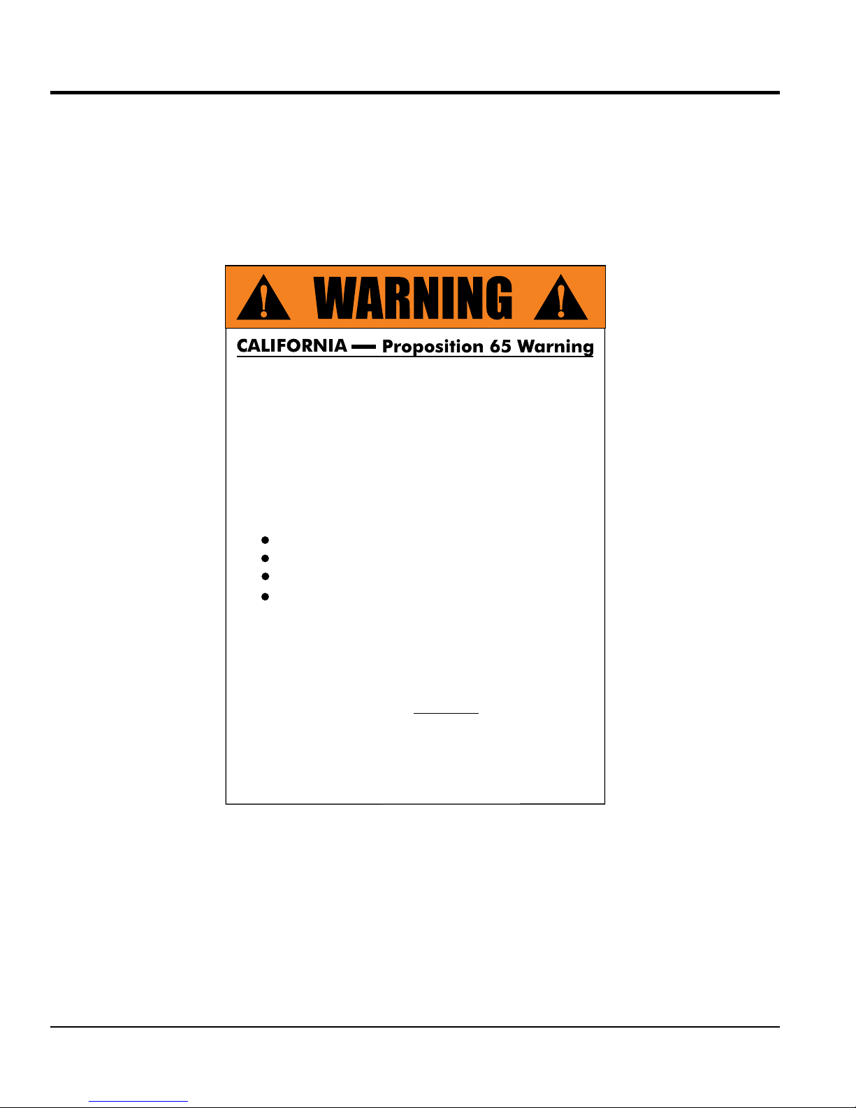
PROPOSITION 65 WARNING
Engine exhaust and some of
its constituents, and some dust created
by power sanding, sawing, grinding,
drillingandotherconstructionactivities
contains chemicals known to the State
of California to cause cancer, birth
defects and other reproductive harm.
Some examples of these chemicals are:
Leadfromlead-basedpaints.
Crystallinesilicafrombricks.
Cementandothermasonryproducts.
Arsenicandchromiumfromchemically
treatedlumber.
Your risk from these exposures varies,
dependingonhowoftenyoudo this type
of work. To reduce your exposure to
these chemicals: work in aALWAYS
well ventilated area, and work with
approved safety equipment, suchas
dust masks that are specially designed
to filter out microscopic particles.
PAGE 2 — SP1G CONCRETE SAW • OPERATION MANUAL — REV. #3 (09/07/17)
Page 3

SILICOSIS WARNING
WARNING
SILICOSIS WARNING RESPIRATORY HAZARDS
Grinding/cutting/drilling of masonry, concrete, metal and
other materials with silica in their composition may give
off dust or mists containing crystalline silica. Silica is a
basic component of sand, quartz, brick clay, granite and
numerous other minerals and rocks. Repeated and/or
substantial inhalation of airborne crystalline silica can
cause serious or fatal respiratory diseases, including
silicosis.In addition, California and some other
authorities have listed respirable crystalline silica as a
substance known to cause cancer. When cutting such
materials, always follow the respiratory precautions
mentioned above.
WARNING
Grinding/cutting/drilling of masonry, concrete, metal and
other materials can generate dust, mists and fumes
containing chemicals known to cause serious or fatal
injury or illness, such as respiratory disease, cancer,
birth defects or other reproductive harm. If you are
unfamiliar with the risks associated with the particular
process and/or material being cut or the composition of
the tool being used, review the material safety data
sheet and/or consult your employer, the material
manufacturer/supplier, governmental agencies such as
OSHA and NIOSH and other sources on hazardous
materials. California and some other authorities, for
instance, have published lists of substances known to
cause cancer, reproductive toxicity,or other harmful
effects.
SP1G CONCRETE SAW • OPERATION MANUAL — REV. #3 (09/07/17) — PAGE 3
Control dust, mist and fumes at the source where
possible. In this regard use good work practices and
follow the recommendations of the manufacturers or
suppliers, OSHA/NIOSH, and occupational and trade
associations.Water should be used for dust
suppression when wet cutting is feasible. When the
hazards from inhalation of dust, mists and fumes cannot
be eliminated, the operator and any bystanders should
always wear a respirator approved by NIOSH/MSHA for
the materials being used.
Page 4

SP1G Concrete Saw
Proposition 65 Warning ........................................... 2
Silicosis Warning ..................................................... 3
Table Of Contents .................................................... 4
Parts Ordering Procedures ...................................... 5
Safety Information .............................................. 6-11
Specifications ................................................... 12-13
Dimensions ............................................................ 14
General Information ............................................... 15
Components ..................................................... 16-17
Basic Engine .......................................................... 18
Inspection ......................................................... 19-24
Operation .......................................................... 25-27
Maintenance ..................................................... 28-29
Troubleshooting ................................................ 30-32
TABLE OF CONTENTS
NOTICE
Specifications are subject to change without notice.
PAGE 4 — SP1G CONCRETE SAW • OPERATION MANUAL — REV. #3 (09/07/17)
Page 5
PARTS ORDERING PROCEDURES
www.multiquip.com
Ordering parts has never been easier!
If you have an MQ Account, to obtain a Username
parts@multiquip.
To obtain an MQ Account, contact your
Effective:
, 2006
Choose from three easy options:
January 1
st
Best Deal!
Order via Internet (Dealers Only):
Order parts on-line using Multiquip’s SmartEquip website!
■ View Parts Diagrams
■ Order Parts
■ Print Specification Information
Goto www.multiquip.com and click on
Order Parts
to log in and save!
Order via Fax (Dealers Only):
All customers are welcome to order parts via Fax.
Domestic (US) Customers dial:
1-800-6-PARTS-7 (800-672-7877)
Order via Phone:
Non-Dealer Customers:
Contact your local Multiquip Dealer for
parts or call 800-427-1244 for help in
locating a dealer near you.
and Password, E-mail us at:
com.
District Sales Manager for more information.
Use the internet and qualify for a 5% Discount
on Standard orders for all orders which include
complete part numbers.*
Fax your order in and qualify for a 2% Discount
on Standard orders for all orders which include
complete part numbers.*
Domestic (US) Dealers Call:
1-800-427-1244
International Customers should contact
their local Multiquip Representatives for
Parts Ordering information.
Note: Discounts Are Subject To Change
Note: Discounts Are Subject To Change
When ordering parts, please supply:
❒ Dealer Account Number
❒ Dealer Name and Address
❒ Shipping Address (if different than billing address)
❒ Return Fax Number
❒ Applicable Model Number
❒ Quantity, Part Number and Description of Each Part
NOTICE
All orders are treated as Standard Orders and will
ship the same day if received prior to 3PM PST.
WE ACCEPT ALL MAJOR CREDIT CARDS!
SP1G CONCRETE SAW • OPERATION MANUAL — REV. #3 (09/07/17) — PAGE 5
❒ Specify Preferred Method of Shipment:
✓ UPS/Fed Ex ✓ DHL
■ Priority One ✓ Tr uck
■ Ground
■ Next Day
■ Second/Third Day
Page 6
SAFETY INFORMATION
Do not operate or service the equipment before reading
the entire manual. Safety precautions should be followed
at all times when operating this equipment.
Failure to read and understand the safety
messages and operating instructions could
result in injury to yourself and others.
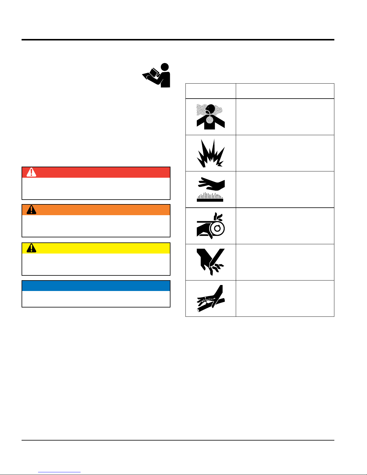
SAFETY MESSAGES
The four safety messages shown below will inform you
about potential hazards that could injure you or others. The
safety messages specifi cally address the level of exposure
to the operator and are preceded by one of four words:
DANGER, WARNING, CAUTION
SAFETY SYMBOLS
Potential hazards associated with the operation of this
equipment will be referenced with hazard symbols which
may appear throughout this manual in conjunction with
safety messages.
DANGER
Indicates a hazardous situation which, if not avoided,
WILL result in DEATH or SERIOUS INJURY.
WARNING
Indicates a hazardous situation which, if not avoided,
COULD result in DEATH or SERIOUS INJURY.
CAUTION
Indicates a hazardous situation which, if not avoided,
COULD result in MINOR or MODERATE INJURY.
or NOTICE.
Symbol Safety Hazard
Lethal exhaust gas hazards
Explosive fuel hazards
Burn hazards
Rotating parts hazards
Cutting and crushing hazards
NOTICE
Addresses practices not related to personal injury.
PAGE 6 — SP1G CONCRETE SAW • OPERATION MANUAL — REV. #3 (09/07/17)
Hydraulic fluid hazards
Page 7
GENERAL SAFETY
NOTICE
This equipment should only be operated by trained and
Whenever necessary, replace nameplate, operation and
Manufacturer does not assume responsibility for any
accident due to equipment modifi cations. Unauthorized
use accessories or attachments that are not
recommended by Multiquip for this equipment. Damage
keep
Also, know the phone numbers
fi re department.
This information will be invaluable in the case of an
SAFETY INFORMATION
WARNING
Adherence to the OSHA 2017 Ruling governing
Occupational Exposure to Respirable Crystalline Silica,
requires that all sawing operations MUST BE conducted
with High Effi ciency Particulate Air (HEPA) vacuum
system connected to the discharge port of the blade
guard.
CAUTION
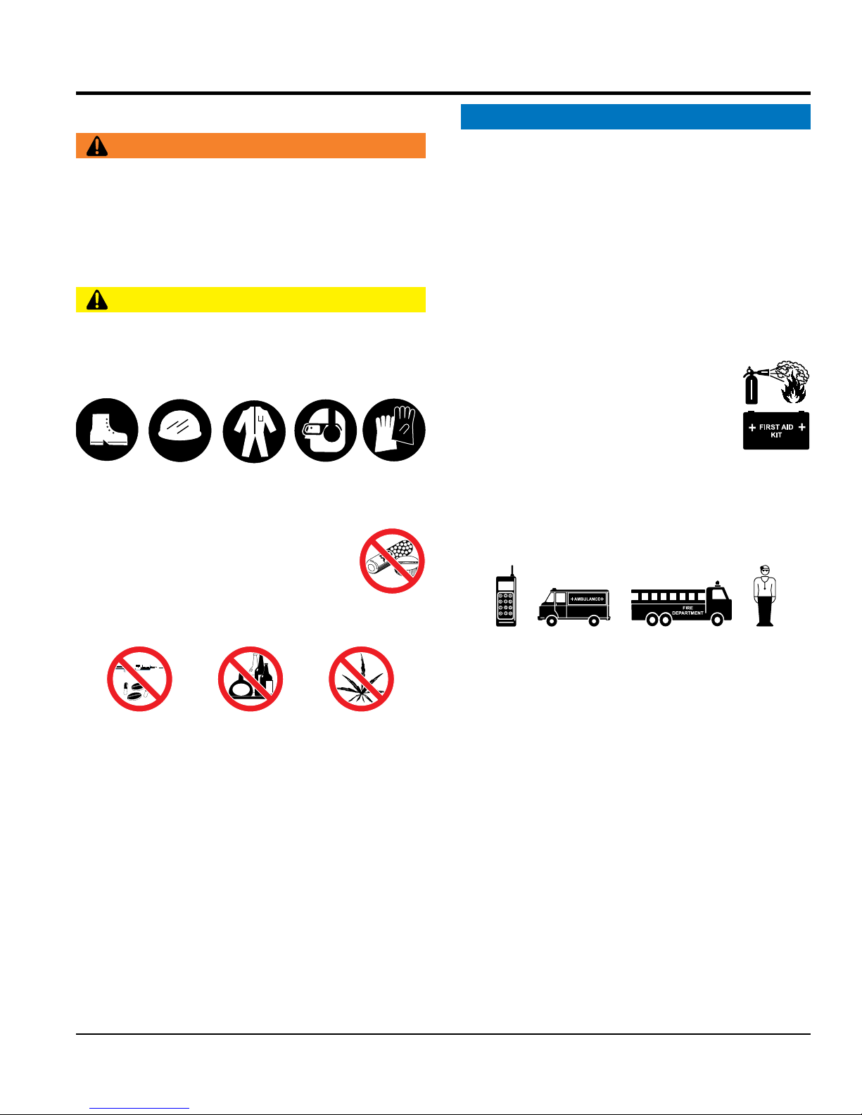
NEVER operate this equipment without proper protective
clothing, shatterproof glasses, respiratory protection,
hearing protection, steel-toed boots and other protective
devices required by the job or city and state regulations.
Avoid wearing jewelry or loose fi tting clothes that may
snag on the controls or moving parts as this can cause
serious injury.
NEVER operate this equipment when not
feeling well due to fatigue, illness or when
under medication.
NEVER operate this equipment under the
infl uence of drugs or alcohol.
qualifi ed personnel 18 years of age and older.
safety decals when they become diffi cult read.
equipment modifi cation will void all warranties.
NEVER
to the equipment and/or injury to user may result.
ALWAYS know the location of the nearest
fi re extinguisher.
ALWAYS know the location of the nearest
fi rst aid kit.
ALWAYS know the location of the nearest phone or
a phone on the job site.
of the nearest ambulance, doctor and
emergency.
ALWAYS clear the work area of any debris, tools, etc.
that would constitute a hazard while the equipment is
in operation.
No one other than the operator is to be in the working
area when the equipment is in operation.
DO NOT use the equipment for any purpose other than
its intended purposes or applications.
SP1G CONCRETE SAW • OPERATION MANUAL — REV. #3 (09/07/17) — PAGE 7
Page 8
SAW SAFETY
NOTICE
placed on appropriate
blocks or jackstands when performing maintenance that
If saw has brakes, ensure brakes are applied when
leaving or when using on a slope. Some saws utilize a
brake system where the brakes are automatically applied
If saw has a parking brake, ensure that the parking brake
is engaged and holds the saw safely in place when
parking on a slope. Turning the saw across the angle of
the slope will help prevent accidental downhill movement.
block the saw with appropriate blocks when
start
use on excessive slopes or on extremely
Fix damage to machine and replace any broken parts
Make sure there is no buildup of concrete, grease, oil or
store equipment properly when it is not being
used. Equipment should be stored in a clean, dry location
out of the reach of children and unauthorized personnel.
SAFETY INFORMATION
DANGER
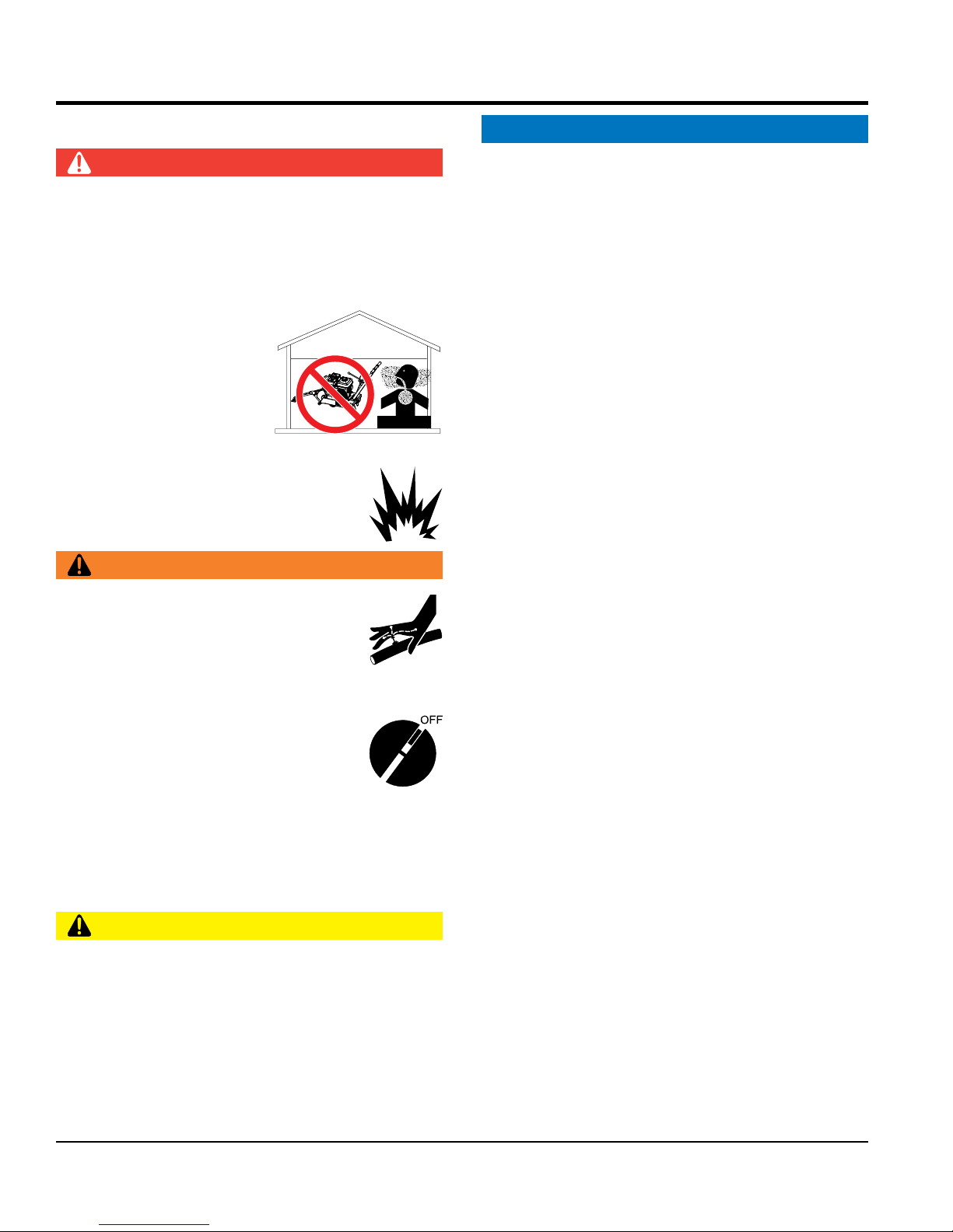
Engine fuel exhaust gases contain poisonous carbon
monoxide. This gas is colorless and odorless, and can
cause death if inhaled.
The engine of this equipment requires an adequate free
fl ow of cooling air. NEVER operate this equipment in any
enclosed or narrow area
where free fl ow of the air is
restricted. If the air fl ow is
restricted it will cause injury
to people and property and
serious damage to the
equipment or engine.
NEVER operate the equipment in an explosive
atmosphere or near combustible materials. An
explosion or fi re could result causing severe
bodily harm or even death.
WARNING
If applicable, NEVER use your hand to fi nd
hydraulic leaks. Use a piece of wood or
cardboard. Hydraulic fl uid injected into the
skin must be treated by a knowledgeable
physician immediately or severe injury or
death can occur.
Accidental starting can cause severe injury
or death. ALWAYS place the ON/OFF
switch in the OFF position.
DANGEROUS
GAS FUMES
ALWAYS ensure saw is securely
requires elevation of the saw.
when the engine is stopped.
ALWAYS
leaving the saw parked on a slope.
To prevent unexpected loss of control, DO NOT
engine on a sloping surface.
DO NOT
uneven surfaces.
ALWAYS keep the machine in proper running condition.
immediately.
debris on the machine.
ALWAYS
NEVER disconnect any emergency or safety devices.
These devices are intended for operator safety.
Disconnection of these devices can cause severe injury,
bodily harm or even death. Disconnection of any of these
devices will void all warranties.
CAUTION
Anytime the saw is lifted onto its nose or tilted fully
back, such as for maintenance access, the high end of
the saw MUST be blocked up to prevent the possibility
of crush injury.
PAGE 8 — SP1G CONCRETE SAW • OPERATION MANUAL — REV. #3 (09/07/17)
Page 9
SAFETY INFORMATION
BLADE SAFETY
ENGINE SAFETY
operate the engine with heat shields or
remove the engine oil drain plug while the
engine is hot. Hot oil will gush out of the oil tank and
severely scald any persons in the general area of the
Make certain the operator knows how to and is capable
run engine without an air fi lter or with a dirty air
fi lter. Severe engine damage may occur. Service air fi lter
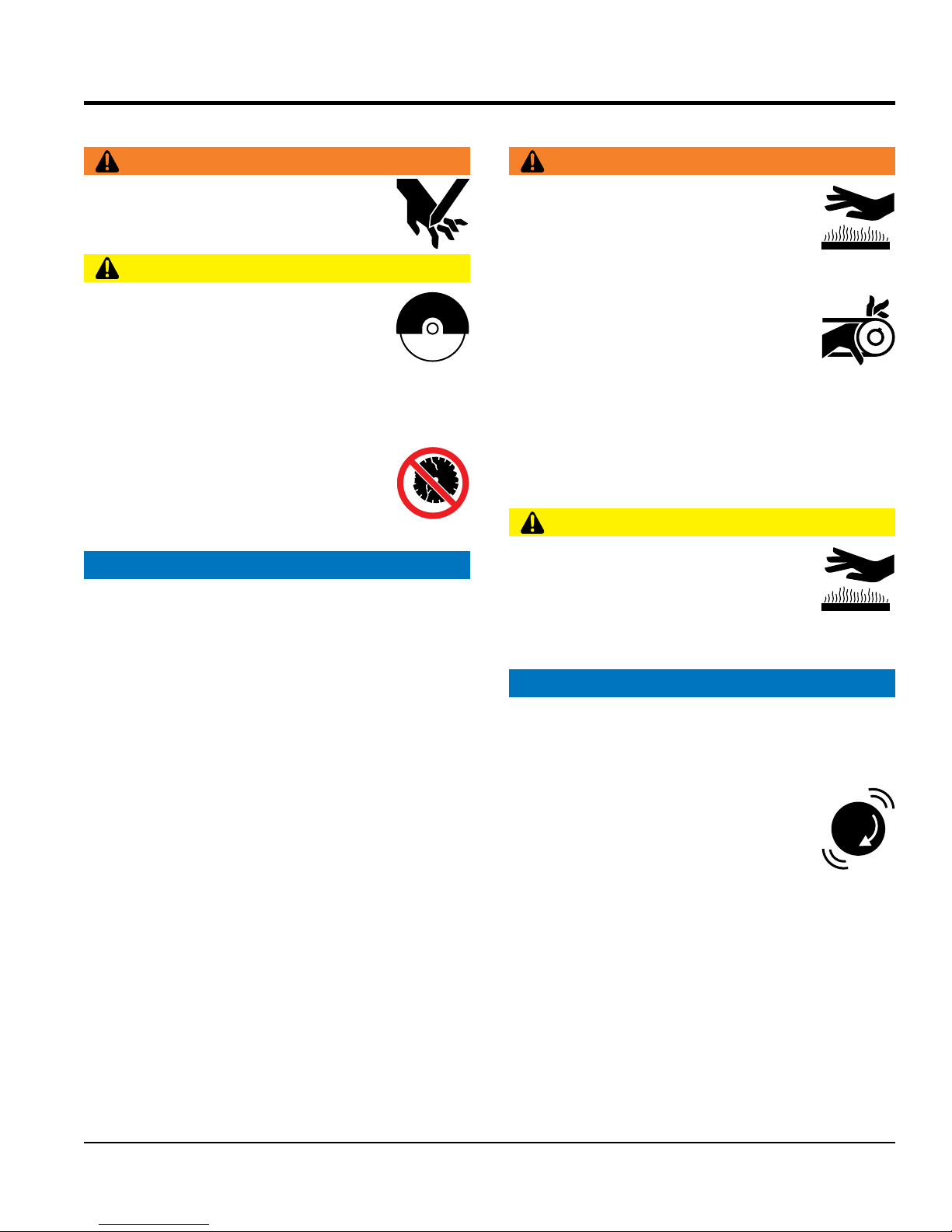
Rotating blade can cut and crush. ALWAYS
keep hands and feet clear while operating
the saw.
NEVER operate the saw without blade
guards and covers in place. Exposure of
the diamond blade must not exceed 180
degrees.
Verify the engine start switch is set to the OFF position
before installing a blade.
ALWAYS inspect blade before each
use. The blade should exhibit no cracks,
dings, or fl aws in the steel centered core
and/or rim. Center (arbor) hole must be
undamaged and true.
NOTICE
Use proper diamond blades and follow blade
manufacturer’s recommendations.
Ensure the 5/8" blade-mounting bolt is tightened to 45-50
foot lbs. of torque.
ALWAYS examine blade flanges for damage and
excessive wear.
Only cut the material that is specifi ed for the diamond
blade. Read the specifi cation of the diamond blade to
ensure the proper tool has been matched to the material
being cut.
DO NOT drop the diamond blade on ground or surface.
Ensure that the blade is mounted for proper operating
direction (upcut).
WARNING
CAUTION
WARNING
DO NOT place hands or fingers inside
engine compartment when engine is
running.
NEVER
guards removed.
Keep fi ngers, hands hair and clothing away
from all moving parts to prevent injury.
ALWAYS shut down the engine before
performing service or maintenance.
DO NOT
saw.
CAUTION
NEVER touch the hot exhaust manifold,
muffl er or cylinder. Allow these parts to cool
before servicing equipment.
of turning the engine OFF in case of an emergency.
NOTICE
NEVER
frequently to prevent engine malfunction.
NEVER tamper with the factory settings
of the engine or engine governor. Damage
to the engine or equipment can result
if operating in speed ranges above the
maximum allowable.
Adhere to the blade manufacturer’s recommendations
on handling, storage and safe usage of blades.
SP1G CONCRETE SAW • OPERATION MANUAL — REV. #3 (09/07/17) — PAGE 9
Page 10
SAFETY INFORMATION
FUEL SAFETY
LIFTING SAFETY
allow any person or animal to stand underneath
Some saws are very heavy and awkward to move around.
attempt to lift the saw by the guards or front
For lifting the saw, a lifting handle in the front of the unit and
grasp points towards the rear of the frame are provided. It
tip the engine to extreme angles during lifting as
it may cause oil to gravitate into the cylinder head, making
use ramps capable of supporting the weight of
Tighten fuel tank cap securely and close fuel cock to
tie down equipment during transport by
Ensure that the diamond blade does not come into contact
transport the saw to or from the job site with the
DANGER
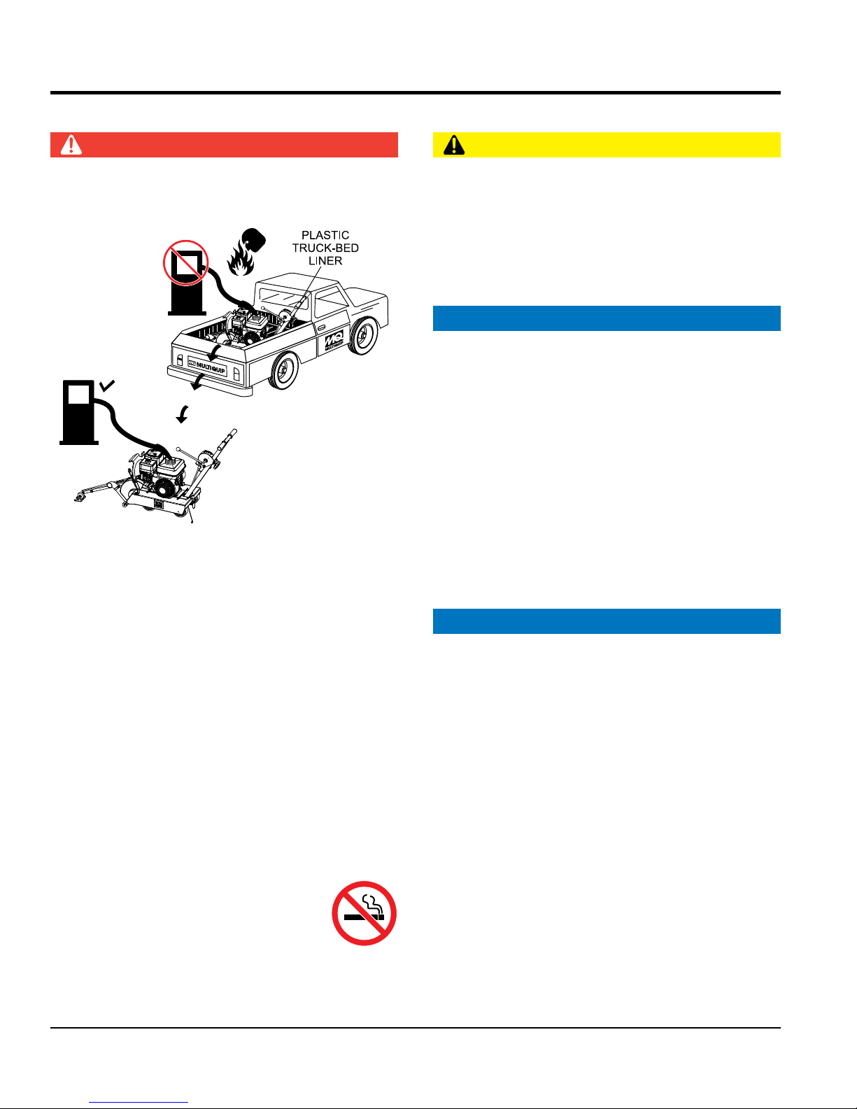
DO NOT add fuel to equipment if it is placed inside truck
bed with plastic liner. Possibility exists of explosion or
fi re due to static electricity
FUEL
DO NOT start the engine near spilled fuel or combustible
fl uids. Fuel is extremely fl ammable and its vapors can
cause an explosion if ignited.
ALWAYS refuel in a well-ventilated area, away from
sparks and open fl ames.
ALWAYS use extreme caution when working with
fl ammable liquids.
DO NOT fi ll the fuel tank while the engine is running
or hot.
DO NOT overfi ll tank, since spilled fuel could ignite if it
comes into contact with hot engine parts or sparks from
the ignition system.
Store fuel in appropriate containers, in well-ventilated
areas and away from sparks and fl ames.
NEVER use fuel as a cleaning agent.
DO NOT smoke around or near the
equipment. Fire or explosion could result
from fuel vapors or if fuel is spilled on a
hot engine.
FUEL
CAUTION
NEVER
the equipment while lifting.
Use proper heavy lifting procedures.
DO NOT
pointers.
NOTICE
is recommended that two persons lift the saw.
NEVER
the engine start diffi cult.
DO NOT lift machine to unnecessary heights.
NEVER lift the equipment while the engine is running.
ALWAYS
the saw and the operator to load and unload the saw.
TRANSPORTING SAFETY
NOTICE
ALWAYS shut down engine before transporting.
prevent fuel from spilling.
ALWAYS
securing the equipment with rope.
with the ground or surface during transportation.
NEVER
blade mounted.
PAGE 10 — SP1G CONCRETE SAW • OPERATION MANUAL — REV. #3 (09/07/17)
Page 11

SAFETY INFORMATION
ENVIRONMENTAL SAFETY/DECOMMISSIONING
Decommissioning is a controlled process used to safely
retire a piece of equipment that is no longer serviceable.
If the equipment poses an unacceptable and unrepairable
safety risk due to wear or damage or is no longer cost
effective to maintain (beyond life-cycle reliability) and is to
be decommissioned (demolition and dismantlement),be
sure to follow rules below.
EMISSIONS INFORMATION
The gasoline engine used in this equipment has been
designed to reduce harmful levels of carbon monoxide
(CO), hydrocarbons (HC) and nitrogen oxides (NOx)
This engine has been certifi ed to meet US EPA Evaporative
Attempting to modify or make adjustments to the engine
emission system by unauthorized personnel without proper
training could damage the equipment or create an unsafe
Additionally, modifying the fuel system may adversely affect
evaporative emissions, resulting in fi nes or other penalties.
The emission control label is an integral part of the emission
If a replacement emission label is needed, please contact
Adherence to the OSHA 2017 Ruling governing
Occupational Exposure to Respirable Crystalline Silica,
conducted
with High Effi ciency Particulate Air (HEPA) vacuum
system connected to the discharge port of the blade
NOTICE
DO NOT pour waste or oil directly onto the ground, down
a drain or into any water source.
Contact your country's Department of
Public Works or recycling agency in your
area and arrange for proper disposal of
any electrical components, waste or oil
associated with this equipment.
When the life cycle of this equipment is over, remove
battery and bring to appropriate facility for lead
reclamation. Use safety precautions when handling
batteries that contain sulfuric acid.
When the life cycle of this equipment is over, it is
recommended that the trowel frame and all other metal
parts be sent to a recycling center.
Metal recycling involves the collection of metal from
discarded products and its transformation into raw
materials to use in manufacturing a new product.
Recyclers and manufacturers alike promote the process
of recycling metal. Using a metal recycling center
promotes energy cost savings.
NOTICE
contained in gasoline exhaust emissions.
emissions requirements in the installed confi guration.
condition.
Emission Control Label
system and is strictly controlled by regulations.
The label must remain with the engine for its entire life.
your authorized Honda Engine Distributor.
SILICA INFORMATION
WARNING
requires that all sawing operations MUST BE
SP1G CONCRETE SAW • OPERATION MANUAL — REV. #3 (09/07/17) — PAGE 11
guard.
Page 12

SPECIFICATIONS
Table 1. Specifications (Saw)
Arbor Size 5/8 in. (15.87 mm)
Blade Capacity 10 in. (254 mm)
Sawing Orientation Upcut
Cutting Depth 3.25 in. (82.6 mm)
Front and Rear Wheels 5 x 1.5 in (127 x 38 mm)
Nominal Mass* 105 lb. (47.6 Kg)
Maximum Operating Mass** 113 lb. (51 Kg)
* Without blade, all fluid tanks empty, any optional
parts removed.
Table 2. Specifications (Engine)
Model HONDA GX200UT2QXC9
** Includes blade, all fluid tanks full, any necessary components
installed
Type
Bore X Stroke
Air-cooled 4 stroke, Single Cylinder, OHV, Gasoline
Engine
2.7 in. X 2.1 in.
(68 mm x 54 mm)
Displacement 12.0 cu-in. (196 cc)
Max Output
Fuel Tank Capacity
Fuel
6.4 H.P./3600 R.P.M.
(4.8 kW, 6.5 PS)
Approx. 0.95 U.S. Gallons
(3.6 Liters)
Unleaded Automobile Gasoline
86 Octane or higher
Lube Oil Capacity 0.63 US qt (0.60 liter)
Speed Control Method Centrifugal Flyweight Type
Starting Method Recoil Start
Dimension (L x W x H)
12.3 x 14.8 X 13.2 in.
(313 X 376 X 335 mm)
Dry Net Weight 35.3 lbs (16 Kg.)
PAGE 12 — SP1G CONCRETE SAW • OPERATION MANUAL — REV. #3 (09/07/17)
Page 13

Table 3. Noise and Vibration Emissions
SPECIFICATIONS
Guaranteed ISO 11201:2010 Based
Sound Pressure Level at Operator Station in dB(A)
Guaranteed ISO 3744:2010 Based
Sound Power Level in dB(A)
Hand-Arm Vibration Per ISO 5349-1:2001
2
∑A(8).
in m/s
95
126
0.52
NOTES:
1. Sound Pressure and Power Levels are “A” weighted Measures per ISO 3744:2010. They are measured with the operating condition of the
machine which generates the most repeatable but highest values of the sound levels. Under normal circumstances, the sound level will vary
depending on the condition of the material being worked upon.
2. The vibration level indicated is the vector sum of the RMS (Root Mean Square) Values of amplitudes on each axis, standardized to an 8 hour
exposure period, and obtained using operating condition of the machine that generates the most repeatable but highest values in accordance
with the applicable standards for the machine.
3. Per EU Directive 2002/44/EC, the daily exposure action value for hand/arm vibration is 2.5 m/s
5 m/s2 ∑A(8).
2
∑A(8). The daily exposure limit value is
SP1G CONCRETE SAW • OPERATION MANUAL — REV. #3 (09/07/17) — PAGE 13
Page 14
C
D
DIMENSIONS
A
B
SIDE VIEW
E
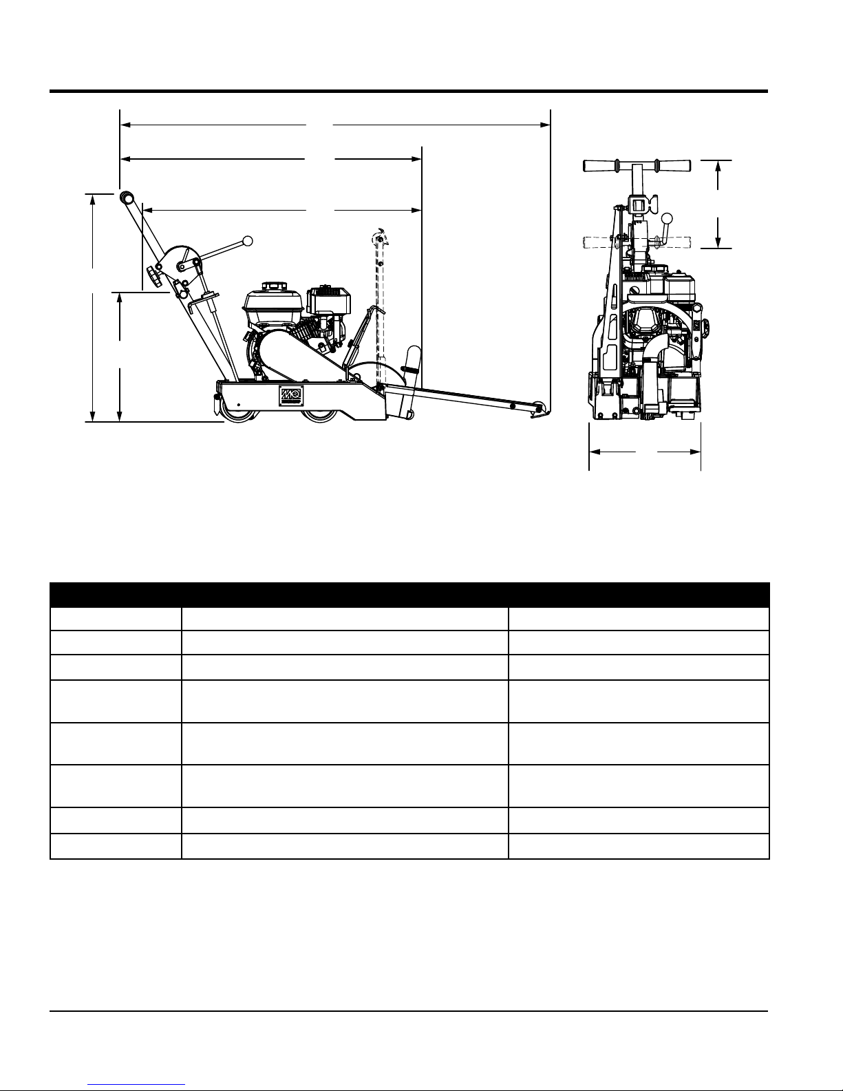
Figure 1. SP1G Dimensions
Table 4. Dimensions
G
F
FRONT VIEW
REFERENCE DESCRIPTION DIMENSION
A Max Height (Handle Bars Fully Raised) 13 in (330 mm)
B Max Height (Handle Bars Fully Lowered) 26.5 in (673.1 mm)
C
D
E
F Max Overall Width 41 in (1041 mm)
G Max Handle Bar Deflection 14 in (355.6 mm)
Max Length (Handle Bars Fully Raised & Front
Pointer Lowered)
Max Length (Handle Bars Fully Raised & Front
Pointer Raised)
Max Length (Handle Bars Fully Lowered & Front
Pointer Raised)
34 in (864 mm)
46 in (1168.4 mm)
43 in (1092.2 mm)
PAGE 14 — SP1G CONCRETE SAW • OPERATION MANUAL — REV. #3 (09/07/17)
Page 15

GENERAL INFORMATION
INTENDED USE
Operate the SP1G Saw, tools and components in
accordance with the manufacturer's instructions. Use of
any other tools for stated operation is considered contrary
to designated use. The risk of such use lies entirely with the
user. The manufacturer cannot be held liable for damages
as a result of misuse.
This saw is not intended for wet cutting (the use of water
sprayed onto the blade during sawing operations). The use
of a High Efficiency Particulate Air (HEPA) dust collector
must be attached to the blade guard discharge port during
operations.
FAMILIARIZATION
This lightweight, compact, and productive saw is designed
for dry sawing of concrete slabs utilizing diamond blades.
The saw has been engineered for general and industrial
flat sawing applications that include: Joint Sawing of Green
Concrete, Decorative Sawing in Cured Concrete, Light
Demolition Sawing and "V" Groove Beveling. The simple
and compact nature of the saw makes it a perfect sawing
tool for one person to operate and transport. The saw
combines innovative features, top quality components, and
a committed attention to state-of-the-art manufacturing.
For peak performance, the saw has been engineered to
operate with a powerful 5.5 HP Honda gasoline engine
with Cyclone Air Filtration. It includes a 10-inch diameter,
green concrete diamond blade. The green concrete blade
allows for fast and clean cuts in concrete recently poured
(4 to 12 hours) at depths from 1/4 inch to 3 1/4 inches.
The precision-machined, reinforced cast frame and steel
chassis assembly are designed to eliminate operational
bending and/or flex that would lead to diminished blade
performance. Also, the frame's general weight-to-strength
ratio and center mounted blade design ensure accurate
tracking in the cut.
A robust blade shaft bearing assembly ensures minimal
flutter and shaft harmonics providing the most advantageous
conditions for a diamond blade at operating speeds.
Heavy-duty front and rear axles, synthetic neoprene wheels
with permanently sealed bearings that are greaseable, and
solid undercarriage assembly, provide years of reliable use.
The SP1G incorporates an innovative posi-lock raise/lower
system that provides precise control of blade orientation.
This system further allows for infinitely adjusting blade
depth control and depth gauge.
The SP1G has a unique front pointer bar that ensures
optimum sawing accuracy. For operator comfort and ease
of transportation and storage, an adjustable locking handle
bar with vibration damping is provided. It also has a lifting
handle for ease of transportation.
Operator control of the saws is safely accomplished with
adjustable handle bars, and a conveniently oriented raise/
lower lever and depth adjustment lever. A shut-off switch
is located next to the handle lock allows the operator to
safely turn the engine off from the operator's position and
away from moving parts.
For maximum performance and return on investment, use
Multiquip Diamond Blades.
SP1G CONCRETE SAW • OPERATION MANUAL — REV. #3 (09/07/17) — PAGE 15
Page 16
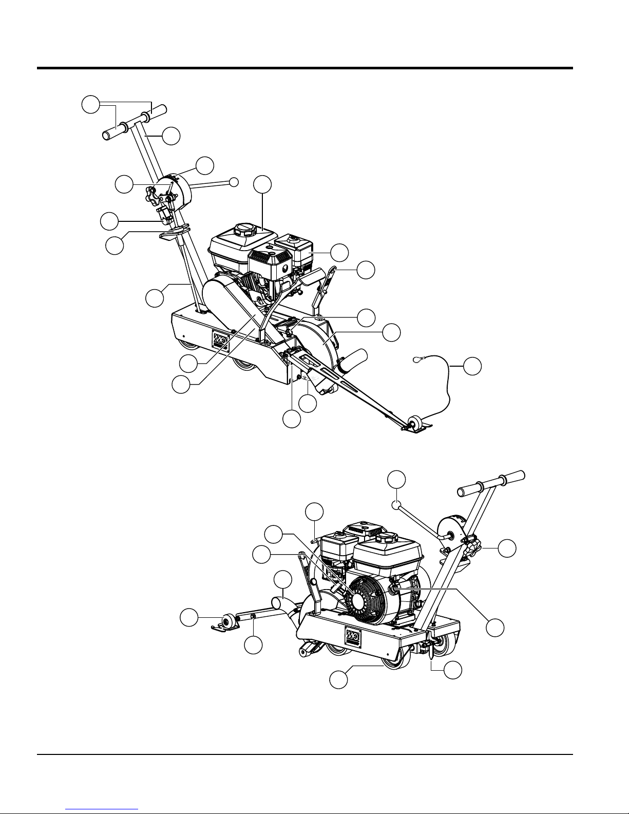
COMPONENTS
1
2
28
21
13
27
20
16
10
14
4
25
26
9
23
8
17
15
11
PAGE 16 — SP1G CONCRETE SAW • OPERATION MANUAL — REV. #3 (09/07/17)
24
6
5
22
12
7
Figure 2. SP1G Components
19
18
3
Page 17

COMPONENTS
Figure 2 shows the location of the basic components for
the SP1G concrete saw. Listed below is a brief explanation
of each component.
1. Hand Grips/Handlebar — When operating the saw,
place both hands on each grip to maneuver the saw.
2. Adjustable Handle — Set to comfortable operating
position.
3. Rear Pointer Guide — Provides rear start orientation
to the snap line.
4. Air Filter — Prevents dirt and debris from entering
the engine air intake. Keep cleaned and replace when
necessary.
5. Recoil Starter Handle — Pull to engage and start
the engine.
6. Recoil Starter Assembly — Engages the engine when
the handle is pulled and rewinds the starter rope when
the handle is released.
7. Wheels/Carriage Assembly — Heavy-duty synthetic
neoprene wheels with permanently sealed ball
bearings.
14. Fuel Tank — Uses unleaded gasoline. Do not overfill.
15. Depth Control Handle — A single throw raise/lower
lever.
16. V-Belt Cover — Remove this cover to gain access
to the V-belt. NEVER operate the saw with this cover
removed.
17. Arbor Shaft Grease Zerk — Conveniently located
for lubrication.
18. On/Off Switch (Engine) — Turn to the ON position to
allow engine to be started and turn to the OFF position
to prevent accidental starting.
19. Handle Lock — Locks handle height to a comfortable
operating position.
20. Depth Stop Rod — Holds blade above working surface
or allows blade to cut into working surface at specified
depth.
21. Shut-off Switch — Located next to the handle lock,
serves both as an Emergency Engine Shut-Off and as
the primary Shutdown switch. This allows the operator
to shutdown the saw safely away from moving parts.
8. Diamond Blade — 5/8-inch (15.87 mm) arbor diameter
and 10-inch blade capacity. The 10-inch diameter
provides for 1/4 to 3 1/4-inch depth of cut.
9. Blade Guard — Covers saw blade and flips up to allow
blade to be changed.
10. Belt Tension Adjuster — Adjusts belt tension.
11. Front Pointer — Assists in straight tracking.
12. Front Pointer Arm — Pivots up for storage and pivots
down for use.
13. Depth Adjust Knob — Turn knob to establish preferred
blade depth.
22. Dust Discharge Port — Allows dust evacuation and
connection point to a vacuum system.
23. Front Pointer Cable — Allows for raise/lower of front
pointer assembly.
24. Lifting Handle — Provides lift point hand hold.
25. Blade Removal Tool — Wrench for blade locking and
blade guard fasteners.
26. Blade Shaft Locking Pin — Locks blade shaft for
blade nut removal.
27. Depth Pointer — Points to blade depth against the
ruler guide.
28. Ruler Guide — Shows depth graduation.
SP1G CONCRETE SAW • OPERATION MANUAL — REV. #3 (09/07/17) — PAGE 17
Page 18
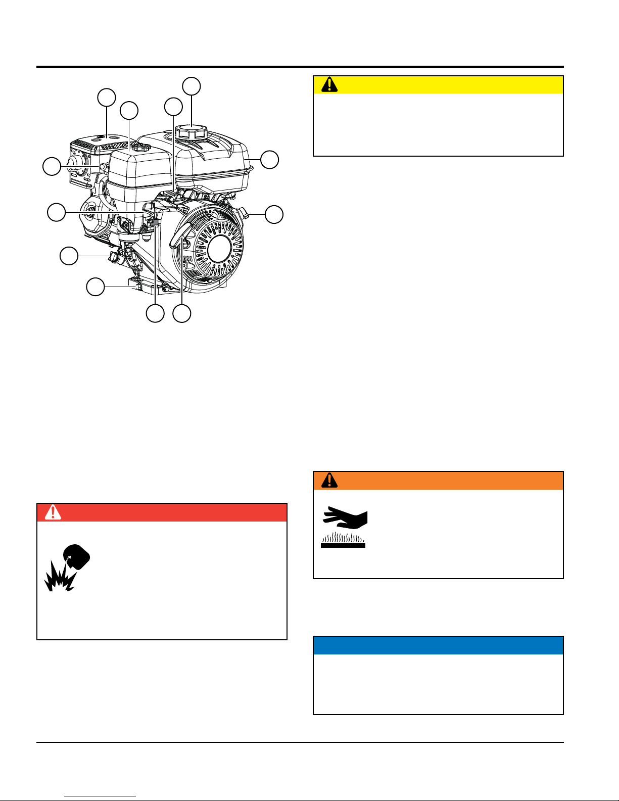
BASIC ENGINE
11
12
10
9
8
7
Figure 3. Engine Components
INITIAL SERVICING
2
1
CAUTION
NEVER disable or disconnect the engine ON/OFF
switch. It is provided for operator safety. Injury may
result if it is disabled, disconnected, or improperly
maintained.
3
5. Recoil Starter — Manual starting mechanism. Slowly
pull the starter grip until resistance is felt, then pull
briskly and smoothly to start the engine.
4
6. Fuel Valve Lever — Open to allow the flow of fuel, and
close to prevent the flow of fuel.
7. Oil Drain Plug — Remove to drain oil from the engine
crankcase.
8. Dipstick/Oil Filler Cap — Remove to determine
if engine oil is low. Add oil through this port as
6
5
recommended in Table 6.
9. Choke Lever — Aids in starting a cold engine, or
starting in cold weather conditions. The choke enriches
the fuel mixture.
The engine (Figure 3) must be checked for proper
lubrication and filled with fuel prior to operation. Refer to
the manufacturer's engine manual for detailed operation
and service instructions.
1. Throttle Lever — Adjusts engine RPM speed.
2. Fuel Filler Cap — Remove to add unleaded gasoline
to the fuel tank. Make sure cap is tightened securely.
DO NOT overfill.
DANGER
DO NOT fill the fuel tank while the engine
is running or hot. In the event of a fuel
spill, DO NOT start the engine until all
fuel residue has been wiped up and the
area surrounding the engine is dry. Fuel
is extremely flammable and can ignite if
it comes into contact with hot engine parts
or sparks from the ignition system.
3. Fuel Tank — Holds unleaded gasoline. Refer to
the manufacturer's engine manual for additional
information.
4. Engine ON/OFF Switch — ON position permits engine
starting, OFF position stops engine operation.
10. Spark Plug — Provides spark to the ignition system.
Set the spark plug gap according to the engine
manufacturer's instructions, and clean the spark plug
once a week.
11. Muffler — Reduces noise and emissions. NEVER
touch the muffler while it is hot.
WARNING
Engine components can generate extreme
heat. To prevent burns, DO NOT touch
these areas while the engine is running
or immediately after operating. NEVER
operate the engine with the muffler
removed.
12. Air Cleaner — Prevents dirt and other debris from
entering the fuel system. Remove the wing nut on top
of the air cleaner to gain access to the filter elements.
NOTICE
Operating the engine without an air filter, or with a
damaged or worn air filter in need of replacement, will
allow dirt to enter the engine, causing rapid engine
wear.
PAGE 18 — SP1G CONCRETE SAW • OPERATION MANUAL — REV. #3 (09/07/17)
Page 19
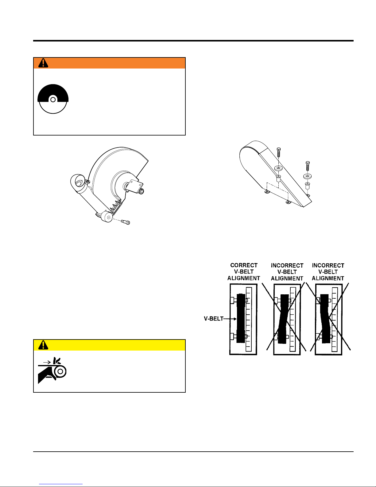
INSPECTION
BLADE GUARD
WARNING
NEVER operate the saw without blade
guards and covers in place. DO NOT
operate with the front of the blade guard
raised. The blade exposure cannot exceed
180 degrees during operation. Adhere to the
safety guidelines of the American National
Standards Institute (ANSI) B7.1 and B7.5.
V-belt Alignment and Tensioning
This concrete saw is equipped with a premium V-belt that
has been aligned and tensioned by factory personnel. The
V-belt must be aligned and tensioned for proper operation
of the saw.
Use the following procedure to check the alignment of
V-belt:
1. Remove the bolts that secure the V-belt cover (Figure 5)
to the saw frame.
Figure 5. V-Belt Cover
Figure 4. Blade Guard
Check the following on the blade guard (Figure 4):
Ensure the capacity of the blade guard matches the
diameter of your diamond blade.
Check that the guard is bolted firmly upon the saw frame.
V-BELT CHECK
A worn or damaged V-belt can adversely affect the
performance of the saw. If the V-belt is defective or worn,
replace the V-belt as outlined in the maintenance section.
CAUTION
NEVER attempt to check the V-belt with the
engine running. Severe injury can occur.
Keep fingers, hands, hair and clothing
away from all moving parts.
2. Check uniform parallelism (Figure 6) of V-belt and
pulley (sheaves). Use a straight-edge or machinist's
square against both pulleys and adjust both pulleys
until equally aligned.
Figure 6. Pulley Alignment
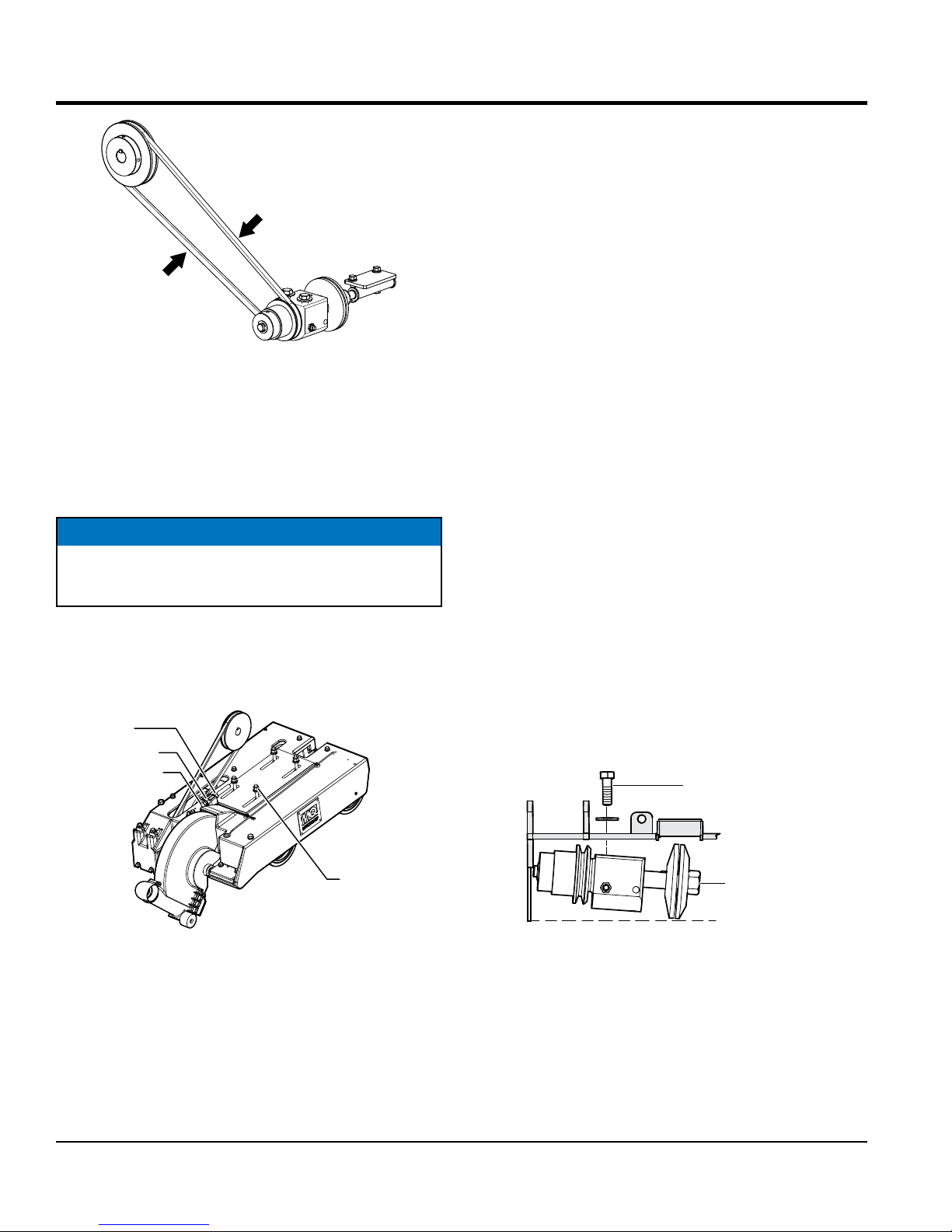
3. Check V-belt tension by using a tension meter
(6.0 – 9.0 lbs.) against the inside belt at a mid point
between the two pulleys, or by deflecting the center
belt at a mid point 3/8" (10 mm) to 1/2" (13 mm). See
Figure 7.
SP1G CONCRETE SAW • OPERATION MANUAL — REV. #3 (09/07/17) — PAGE 19
Page 20
INSPECTION
3. Tighten the adjusting hex screw while holding the
engine in place to maintain pulley alignment. A
screwdriver can be used as a lever at the rear belt
guard mounting boss to hold the back of the engine
while adjusting V-belt tension.
4. Retighten the locking nut and jam nut.
5. With V-belt held in proper alignment (engine parallel
with the frame), retighten the 4 engine mounting
hex screws. Verify that all hex screws are properly
tightened.
Figure 7. V-Belt Tension Check
4. DO NOT overtighten or undertighten the V-belt. Severe
damage can occur to the saw and engine crankshaft
if the belt is over-tensioned. A decrease of power to
the blade and poor performance will result if the belt
is under-tensioned (loose on pulleys).
NOTICE
V-belt alignment must be rechecked after adjusting
belt tension.
V-belt Tightening
JAM NUT
LOCKING NUT
ADJUSTING
HEX
SCREW
V-belt Removal and Replacement
If the V-belt becomes worn or damaged, replace it with
new one.
1. Remove the 3 hex screws holding the V-belt guard and
remove the guard.
2. Loosen the 4 engine mounting hex screws (Figure 8).
3. Loosen locking nut on the V-belt tension adjuster.
4. Loosen the tension on the V-belt by turning the tension
adjuster hex screw.
5. Push the engine forward to provide slack in the V-belt.
6. Remove the belt from the main engine pulley.
7. Remove the two arbor shaft hex screws allowing the
outside of the shaft to drop (Figure 9).
8. Remove the V-belt.
ARBOR SHAFT
HEX SCREW
Figure 8. V-Belt Tension Adjustment
1. With V-belt guard removed, loosen the 4 engine
mounting hex screws (Figure 8).
2. Loosen the locking nut and jam nut on the V-belt tension
adjuster.
PAGE 20 — SP1G CONCRETE SAW • OPERATION MANUAL — REV. #3 (09/07/17)
ENGINE
MOUNTING
HEX SCREWS
ARBOR
SHAFT
Figure 9. V-Belt Removal
9. Reinstall new V-belt.
10. Reinstall and tighten arbor shaft hex screws.
11. With V-belt held in proper alignment, retighten the 4
engine mounting hex screws. (Follow V-belt Tightening
procedure.)
12. Reinstall belt guard with 3 hex screws.
Page 21
INSPECTION
BLADE
Use the following type of blade:
Steel Core Segmented or
Diamond Rim Cutting Wheel.
Any other type of blade should not to be used. See Table
5 for specific blade usage for material.
Table 5. Material Listing and Blade Selection
Material Blade
Cured Concrete Cured Concrete Blade
Green Concrete Green Concrete Blade
Asphalt Asphalt Blade
Asphalt over Concrete Asphalt/Concrete Blade
WARNING
Failure to thoroughly inspect the
diamond blade for operational safety
could result in damage to the blade,
the saw, and may cause injury to the
user or others in the operating area. All
damaged blades must be discarded.
NOTICE
Adhere to the blade manufacturer's recommendations
on handling, storage, and safe usage of blades.
1
MAX. RPM
7
6
2
SPECIFICATIONS
3
4
5
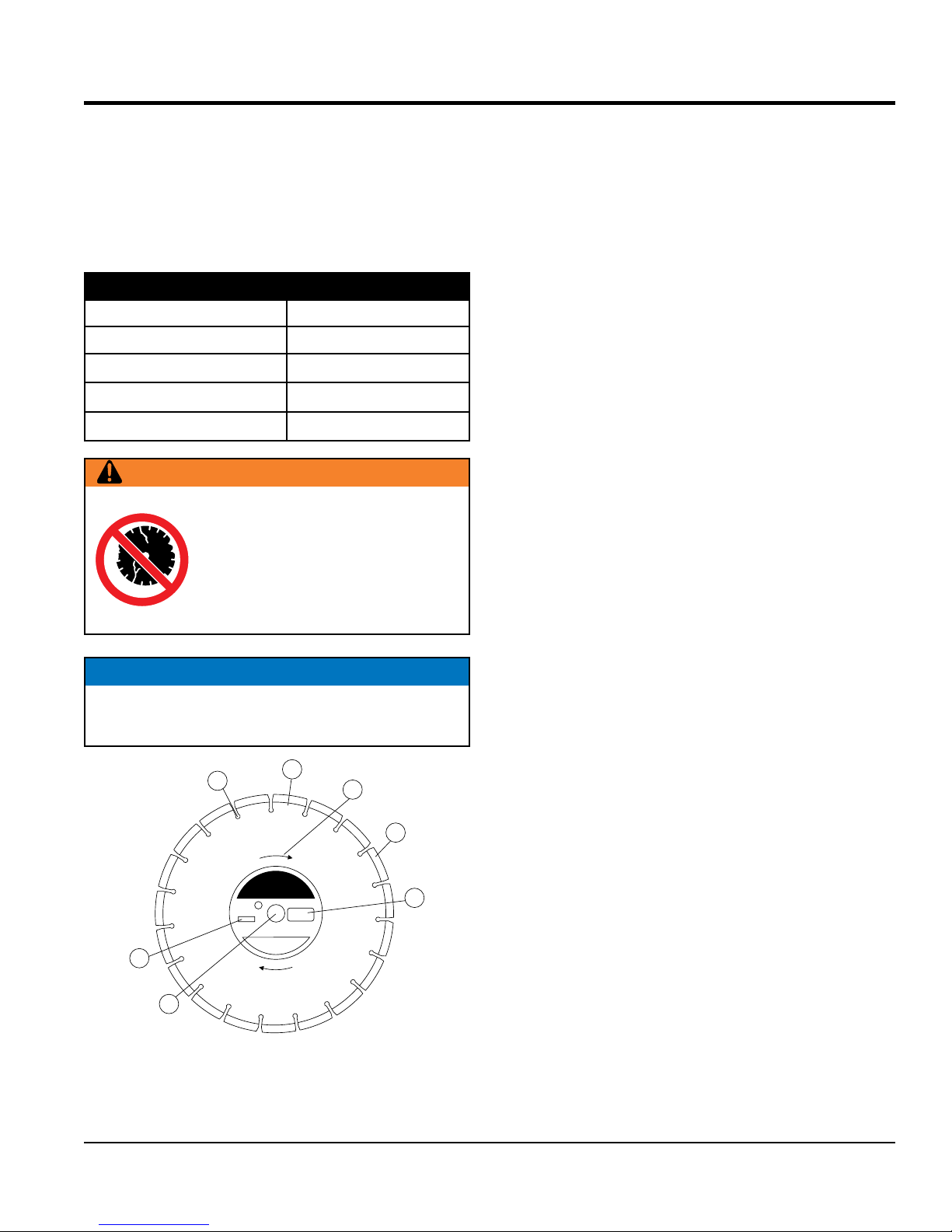
1. Stress Relief Holes (Gullets) — Check the steel core for
cracks that may have propagated from the slots and/or
gullets. Cracks indicate extreme fatigue failure and if sawing
continues, catastrophic failure will occur.
2. Edge Of The Steel Core — Check the diameter edge for
discoloration (blue oxidation) indicating an overheating
condition caused by insufficient cooling water/air.
Overheating of blades may lead to loss of core tension and/
or increase the possibility for blade failure. Check to make
sure the steel core’s width is uniform about the rim of the
blade, and not succumbing to an “under cutting” condition
brought about by highly abrasive material or improper under
cutting core protection.
3. Directional Arrow — Check to ensure that the blade is
oriented properly on the blade shaft for sawing. Reference
the directional arrow in the blade and place it so the direction
of rotation “downcuts” with the turn of the shaft.
4. Diamond Segment or Rim — Ensure there are no cracks,
dings, or missing portions of the diamond segment/rim. DO
NOT use a blade that is missing a segment or a portion of
the rim. Damaged and/or missing segments/rims may cause
damage to your saw, and injury to the user or others in the
operating area.
5. Specifications — Ensure that the blade specifications, size,
and diameter properly match up to the sawing operation.
Utilizing a diamond blade not matched properly to the task
may result in poor performance and/or blade damage.
6. Arbor Hole — It is essential that the arbor hole diameter
properly matches the blade, and that it is free from
distortions. Correct blade flanges (collars) must be used.
The inside face of the flanges must be clean and free of
debris. An out of round arbor condition will cause damage
to the blade and the saw.
7. MAX RPM — This RPM reference is the maximum safe
operating speed for the blade selected. DO NOT use blades
rated at a lower rotational speed than the rated RPM of the
saw (6000 RPM). Exceeding the MAX RPM is dangerous
and may cause poor performance and may damage the
blade. All blades must be designed to meet or exceed the
maximum spindle RPM.
Figure 10. Diamond Blade
SP1G CONCRETE SAW • OPERATION MANUAL — REV. #3 (09/07/17) — PAGE 21
Page 22
INSPECTION
Selecting Diamond Blades
Selecting the diamond blade type and grade defines how
the blade will perform both in cutting speed and blade life.
Selection of the proper diamond blade consists of:
Material to be Cut
Type of Saw Being Used
Spindle Speed of Saw
Hardness Characteristics of the Material
Performance Expectations
Factors for sawing economy:
Type of Blade
Depth of Cut
Sawing Speed
Characteristics of the Material Being Cut
Blade Speed
A diamond blade’s performance is directly connected to
specific peripheral (rim) speeds.
The following shaft rotational speeds have been factory set
to ensure optimum blade performance.
Blade Replacement
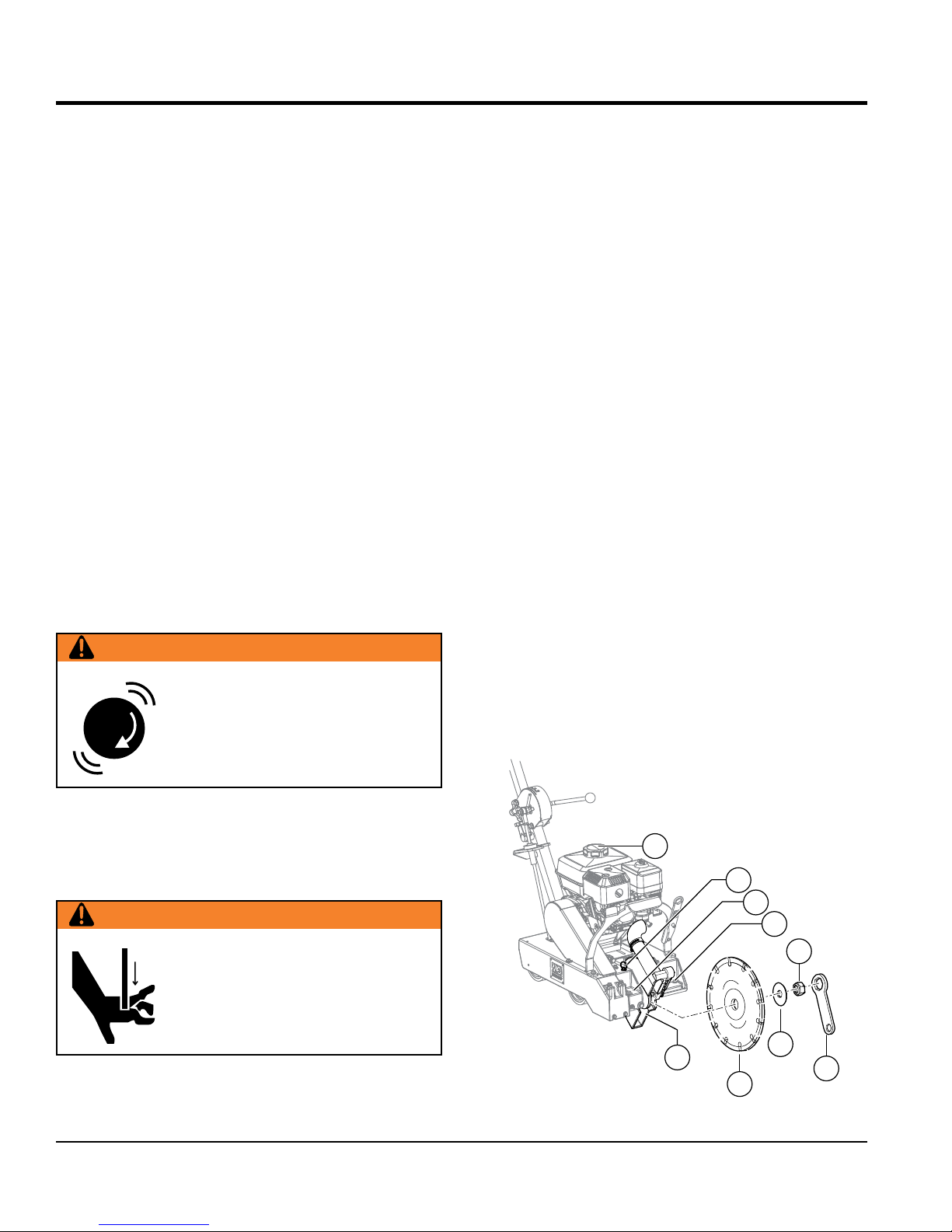
Refer to Figure 11 for location of components.
1. Place the saw in a secure, level work place.
2. Using the supplied Utility Saw Wrench (9), loosen and
remove two Blade Guard Security Bolts (2).
3. Remove the Blade Guard (3).
4. Place the Blade Shaft Locking Pin (4) into the Blade
Shaft Locking Hole (5).
5. Spin the Blade Shaft until the Blade Shaft Locking Pin
seats into the machined hole of the Blade Shaft.
6. Place the proper Diamond Blade (6) firmly against the
Inside Blade Flange.
7. Place the (flat side) Outside Blade Flange (7) against
the Diamond Blade.
8. Thread the Blade Retaining Nut (8) onto the Blade
Shaft against the Outside Blade Flange and torque
to 45-50 ft lbs (standard thread) using the Utility Saw
Wrench (9).
Capacity - 6000 RPM.
WARNING
Operating saw blades at rotational
speeds greater than those specified
by the manufacturer can cause blade
damage and may injure the user or
others in the operating area.
Cutting Depth
The SP1G concrete saw has a capacity for a 10-inch blade
with a 5/8 in. (15.87 mm) arbor diameter. This allows a
cutting range from 0 to 3 ¼ inches.
WARNING
Dropping or forcing the blade onto the
cutting surface can severely damage
the diamond blade and may cause
serious damage to the saw and bodily
harm.
9. Remove Blade Shaft Locking Pin and return it to its
holding position (4).
10. Place the Blade Guard over the Diamond Blade and
into its normal position.
11. Lock Blade Guard in place by replacing the two Blade
Guard Security Bolts (2).
1
4
5
2
8
3
7
9
6
PAGE 22 — SP1G CONCRETE SAW • OPERATION MANUAL — REV. #3 (09/07/17)
Figure 11. Changing the Blade
Page 23
INSPECTION
Cutting Depth Adjustment
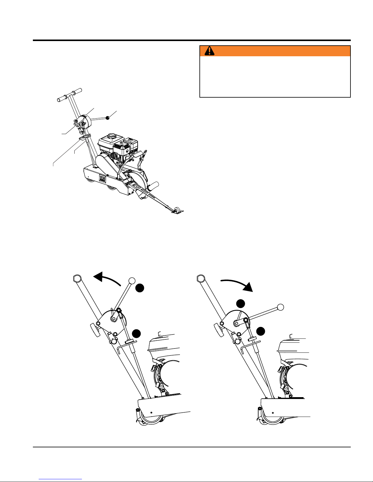
The SP1G Saw is equipped with a Raise/Lower Assembly
that is supported by the following components (Figure 12).
DEPTH
CONTROL
INDICATOR
DEPTH
POINTER
BAR
DEPTH
STOP ROD
DEPTH
ADJUSTMENT
DISK
DEPTH
CONTROL
HANDLE
WARNING
ALWAYS make sure that the shutdown switch and the
engine ON/OFF switch are in the OFF position and the
blade shaft has COMPLETELY STOPPED ROTATING
before performing the following operations.
To adjust the diamond blade to the desired cutting depth,
perform the following steps: Refer to Figure 13.
1. Pull up on the Depth Control Handle (1) until it locks
into place.
2. Mount the desired diamond blade on the blade shaft
and secure as instructed in the Blade Removal and
Replacement section.
3. Turn the Depth Adjust Knob clockwise until it touches
the Depth Stop Bracket (2).
4. Find the set screw on the side of the Depth Adjust
Knob. Every 360° turn (counterclockwise) equals
approximately 1/4" depth of cut.
Figure 12. Raise/Lower Assembly
1
2
5. Turn the Depth Adjust Knob the number of revolutions
to coincide with the depth of cut and double check this
figure against the Depth Pointer (3) and Ruler Guide.
This operation may take several attempts to dial in an
exact depth dimension.
3
2
SP1G CONCRETE SAW • OPERATION MANUAL — REV. #3 (09/07/17) — PAGE 23
Figure 13. Diamond Blade Adjustment
Page 24
BEFORE STARTING
1. Read safety instructions at the beginning of manual.
2. Clean the saw, removing dirt and dust, particularly the
engine cooling air inlet, carburetor and air cleaner.
3. Check the air filter for dirt and dust. If air filter is dirty,
replace air filter with a new one as required.
4. Check carburetor for external dirt and dust. Clean with
dry compressed air.
INSPECTION
UPPER LIMIT
LOWER LIMIT
5. Check fastening nuts and bolts for tightness.
Engine Oil Check
1. To check the engine oil level, place the saw on secure
level ground with the engine stopped. The frame
platform must be level to accurately check the engine
oil.
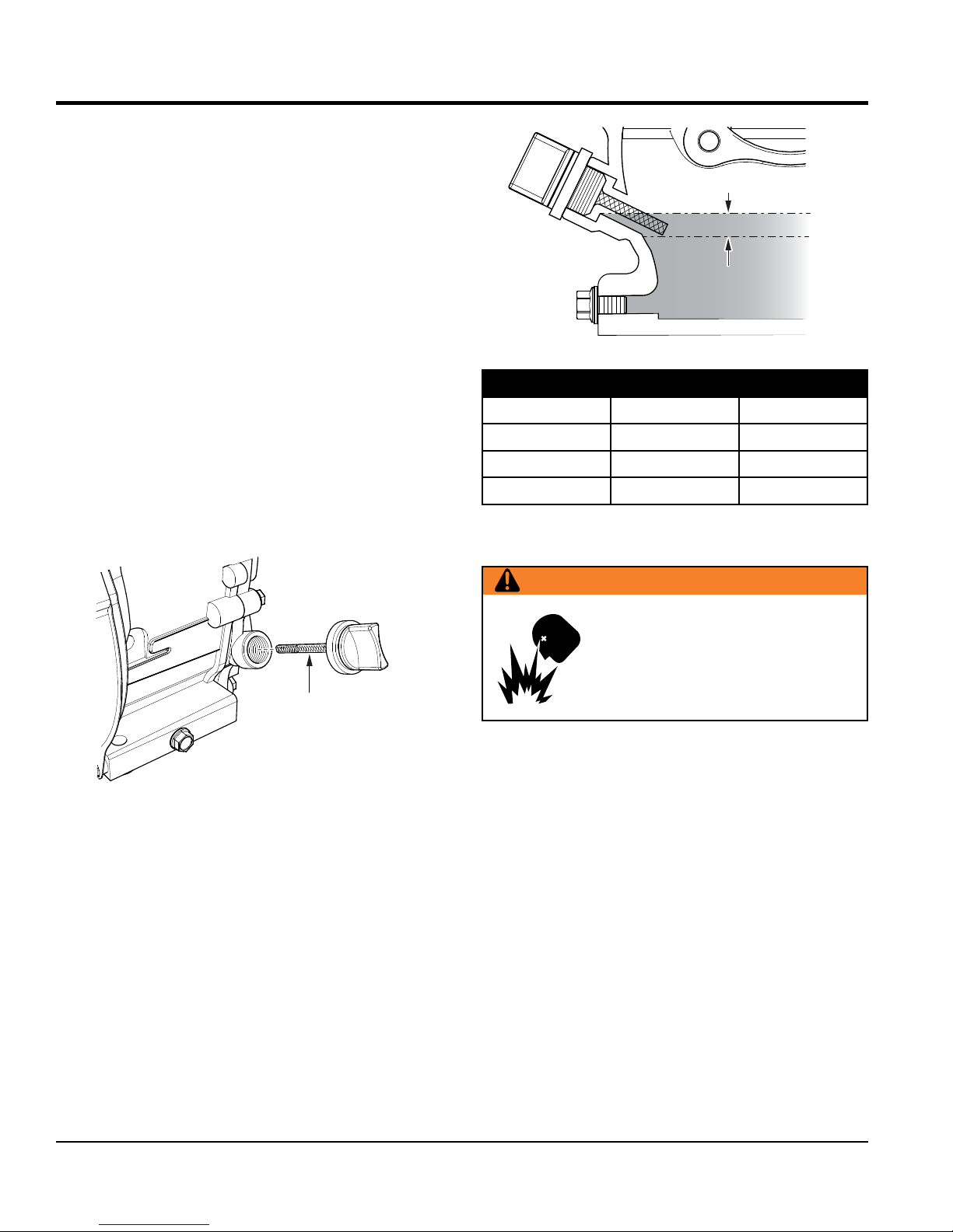
2. Remove the filler dipstick from the engine oil filler hole
(Figure 15) and wipe it clean.
DIPSTICK
Figure 14. Engine Oil Dipstick Removal
Figure 15. Checking Engine Oil
Table 6. Oil Type
Season Temperature Oil Type
Summer 25°C or Higher SAE 10W-30
Spring/Fall 25°C~10°C SAE 10W-30/20
Winter 0°C or Lower SAE 10W-10
Fuel Check
WARNING
Motor fuels are highly flammable and
can be dangerous if mishandled. DO
NOT smoke while refueling. DO NOT
attempt to refuel the saw if the engine
is hot or running.
1. Remove the gasoline cap located on top of fuel tank.
2. Visually inspect to see if fuel level is low. If fuel is low,
replenish with unleaded fuel.
3. Insert and remove the dipstick without screwing it into
the filler neck. Check the oil level shown on the dipstick.
4. If the oil level is low (Figure 16), fill to the edge of the
oil filler hole with the recommended oil type (Table 6).
PAGE 24 — SP1G CONCRETE SAW • OPERATION MANUAL — REV. #3 (09/07/17)
3. When refueling, be sure to use a strainer for filtration.
DO NOT top-off fuel. Wipe up any spilled fuel.
V-belt Check
A worn or damaged V-belt can adversely affect the
performance of the trowel. If a V-belt is defective or worn,
replace the V-belt.
Blade Check
Check for worn or damaged blades. Refer to Blade
Placement section.
Page 25
CAUTION
ENGINE SWITCH
DO NOT attempt to operate the saw until
this manual has been read and thoroughly
understood. Engine operating steps may
vary. See engine manufacturer's operating
manual.
OPERATION
WARNING
When the engine is running the
cutting blade is ALWAYS rotating.
Keep hands and feet clear of rotating
blade. Raise the saw to full height
when maneuvering the saw within
the cutting area.
All displacement of the machine
outside the cutting area must be
carried out with the tool not in rotation.
WARNING
NEVER place hands or feet inside the
belt guard or blade guard while the
engine is running. ALWAYS shut the
engine down before performing any
kind of maintenance on the saw.
CAUTION
Ensure the work area is clear of tools, debris, and
unauthorized people.
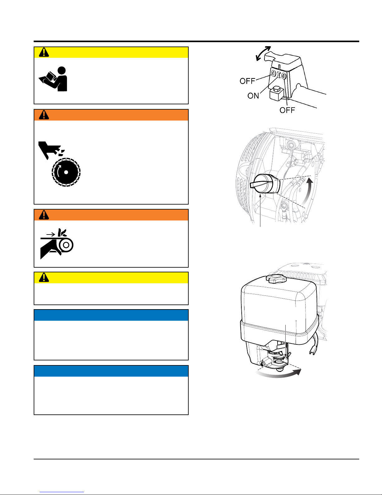
Figure 16. Engine Shutdown Switch
OFF
ON
Figure 17. Engine ON/OFF Switch
2. Place the fuel valve lever (Figure 18) to the ON position.
NOTICE
The saw is equipped with an outlet that provides a
connection to a dust collection bag or vacuum system.
It is recommended that a dust collection bag or vacuum
system is used while the saw is in operation.
NOTICE
The Engine Stop Switch serves both as an Emergency
Engine Shut-Off and as the primary shutdown switch.
This allows the operator to shutdown the saw safely
away from moving parts.
1. Ensure that the engine shutdown switch (Figure 16)
and the engine ON/OFF switch (Figure 17) on the
engine are both in the OFF position to avoid accidental
starting.
SP1G CONCRETE SAW • OPERATION MANUAL — REV. #3 (09/07/17) — PAGE 25
FUEL VALVE
LEVER
OFF
Figure 18. Fuel Valve Lever (ON)
ON
3. Place the engine shutdown switch and the engine
ON/OFF switch on the engine to the ON position.
Page 26
OPERATION
FAST
SLOW
STARTER GRIP
NOTICE
ALWAYS use the Engine Shutdown Safety Switch
located next to the handle lock to shut down the engine.
Shutting the engine off using this switch confirms that
it is functioning properly.
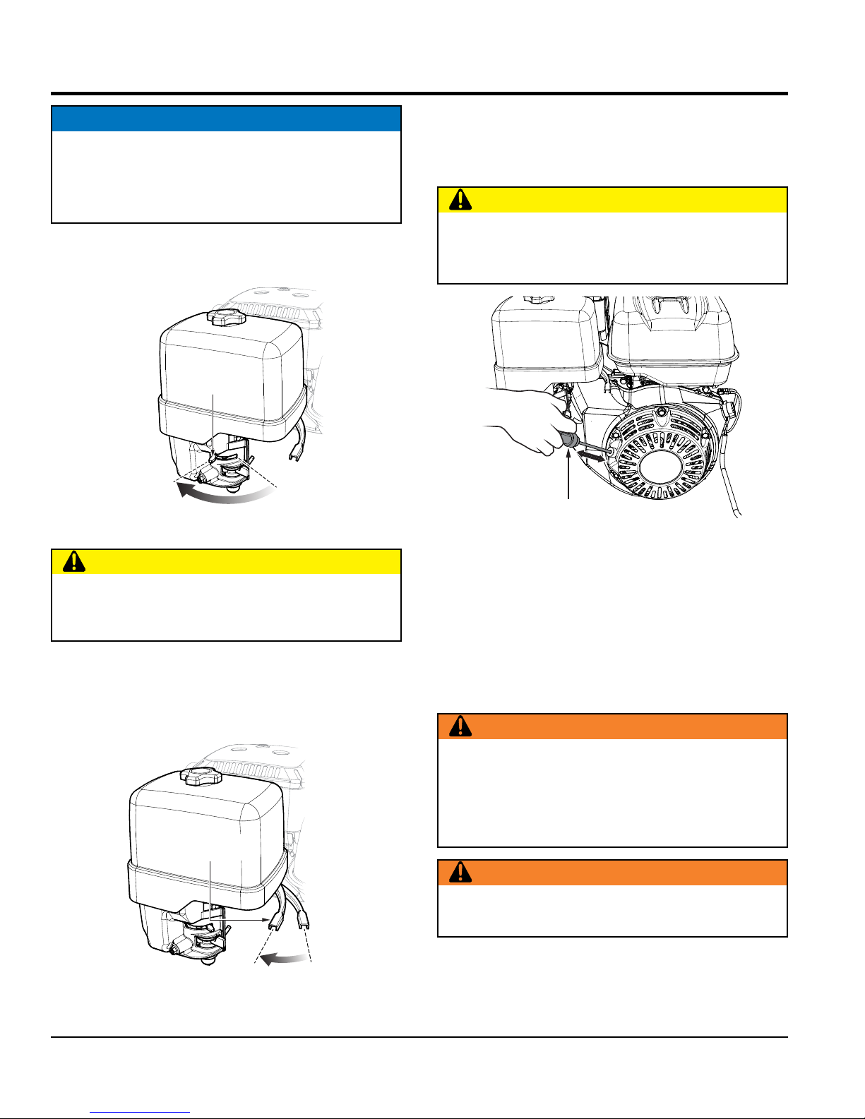
4. Place the choke lever (Figure 19) in the CLOSED
position.
CHOKE LEVER
CLOSE
OPEN
6. Grasp the starter grip (Figure 21) and slowly pull it
out. The resistance becomes the hardest at a certain
position, corresponding to the compression point. Pull
the starter grip briskly and smoothly for starting.
CAUTION
DO NOT pull the starter rope all the way to the end.
DO NOT release the starter rope after pulling. Allow it
to rewind as soon as possible.
Figure 19. Choke Lever
CAUTION
The engine speed has been set at the factory. Changing
the governor speed could damage the blade and/or
the saw.
5. Rotate the throttle lever (Figure 20) halfway between
fast and slow for starting. All sawing is done at full
throttle. The engine governor speed is factory set to
ensure optimum blade operating speeds.
THROTTLE
LEVER
Figure 21. Starter Grip
7. If the engine has started, slowly return the choke lever
(Figure 19) to the OPEN position. If the engine has not
started, repeat steps 1 through 5.
8. Before the saw is placed into operation, run the engine
for several minutes. Check for fuel leaks, and noises
associated with loose guards and/or covers.
9. Rotate the throttle lever (Figure 20) toward full throttle.
WARNING
ALWAYS cut with the saw at FULL THROTTLE.
Attempting to cut with the saw at less than full throttle
could cause the blade to bind or stop abruptly in the
slab resulting in serious injury to the operator or others
in the area.
WARNING
ALWAYS keep clear of rotating or moving parts while
operating this equipment.
Figure 20. Throttle Lever
PAGE 26 — SP1G CONCRETE SAW • OPERATION MANUAL — REV. #3 (09/07/17)
10. To begin sawing, lower the rotating blade allowing it to
cut to the preset depth.
Page 27
OPERATION
11. When blade has reached full cutting depth, slowly walk
behind the saw at a rate that will allow the engine to
operate without losing optimum RPM.
CAUTION
DO NOT try to cut faster than the blade will allow.
Cutting too fast will cause the blade to rise up out of
the cut. Improper cutting rate can decrease the life of
the engine and blades.
12. When the end of the cut has been reached, raise the
blade out of the cut by pulling back on the handlebars
(using a downward pressure) until the raise/lower rod
drops into its slot with the blade in the raised position.
13. If cutting is complete, shut the saw down using the
following shutdown procedure.
STOPPING THE ENGINE
Stopping the engine under normal conditions:
1. Place the engine throttle lever (Figure 20) in the slow
position, and listen for the engine speed to decrease.
Allow engine to run for 2 or 3 minutes for proper
cooldown.
2. Turn the engine shutdown switch (Figure 16) to the
OFF position. Shutting the engine off using this switch
confirms that is functioning properly.
RESTARTING AFTER INTERVENTION
If cutting is interrupted where the engine stops or is
turned off while the blade is still in the cut:
1. Turn engine shutdown switch (next to the handle lock)
to the OFF position.
2. Raise the blade out of the cut.
3. Restart the engine as described in the Startup section.
CAUTION
The only acceptable method for freeing a stuck blade
is to remove the saw from the stuck or pinched blade.
DO NOT try to get the blade unstuck using the Raise/
Lower system or by lifting the saw by the lifting bale, etc.
If cutting is interrupted where the blade is stuck in
the cut:
1. Turn engine shutdown switch (next to the handle lock)
to the OFF position.
2. Remove the blade guard.
3. Remove blade mounting bolt and outer flange.
4. Maneuver the saw away from the stuck blade.
5. A parallel cut made next to the blade may be necessary
to free it.
3. Turn the engine ON/OFF switch (Figure 17) to the
OFF position.
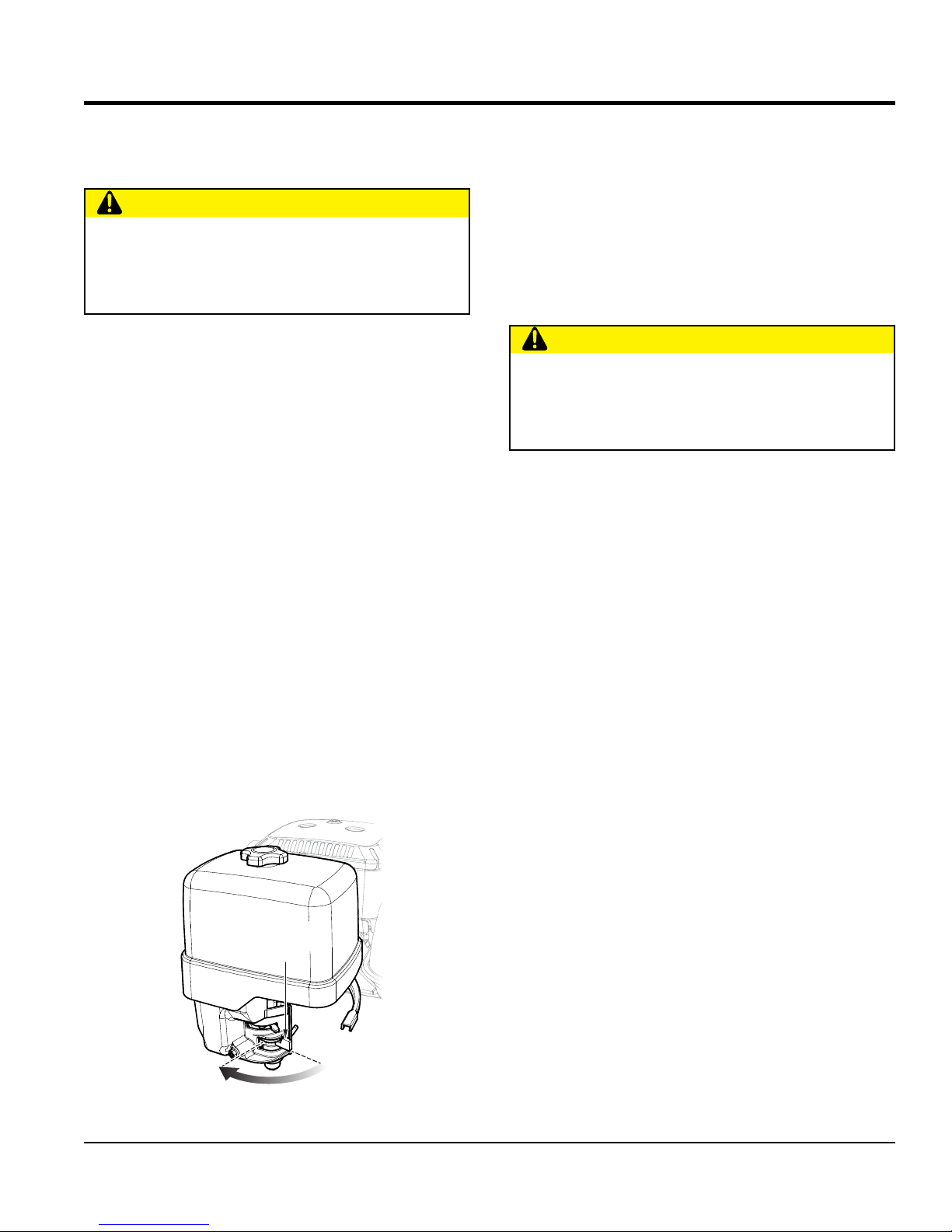
4. Place the fuel valve lever (Figure 22) to the OFF
position.
FUEL VALVE
LEVER
OFF
Figure 22. Fuel Valve Lever (OFF)
ON
SP1G CONCRETE SAW • OPERATION MANUAL — REV. #3 (09/07/17) — PAGE 27
6. Once the blade is freed inspect the blade for damage.
Discard if damaged.
7. Ensure an undamaged, useable blade is installed on
the saw before cutting is resumed with the saw.
Page 28
MAINTENANCE
NOTICE
See the engine manual supplied with your machine
for engine maintenance schedule and troubleshooting
guide.
CAUTION
ALWAYS allow the engine to cool
before servicing. NEVER attempt any
maintenance work on a hot engine.
WARNING
ALWAYS ensure that the engine ON/OFF
switch is in the OFF position and that the
arbor shaft has COMPLETELY STOPPED
ROTATING before performing any of the
following operations:
• Removing or installing blades
• Adjusting front or rear pointers
• Lubricating any components
• Removing engine mounting bolts
• Inspecting, adjusting, or replacing drive
belt, arbor shaft, arbor shaft bearings or
any engine part.
8. The pointer should follow the chalk line as well. If it does
not, adjust the pointer by loosening then tightening the
jam nuts on the pointer until the pointer follows the
same path as the blade.
REAR GUIDE ADJUSTMENT
The rear guide is useful on long runs that allow the operator
to follow the line with less effort as well as cutting up to a
wall where the front pointer is lifted.
1. Chalk out a straight line on the prepared slab or cutting
surface.
2. Cut a straight line about 10 to 12 feet (3 – 4 meters)
in length.
3. Adjust the rear guide until it falls into the cut.
4. The rear guide should ride in the cut freely without
the feel of it pushing the front pointer or blade off line.
If it feels like it is doing so, turn the saw off and after
the blade has COMPLETELY STOPPED ROTATING,
adjust the rear guide by loosening then tightening the
jam nuts on the guide until it rides freely in the cut.
FRONT POINTER ADJUSTMENT
The front pointer and rear guide have been set at the
factory. Perform this procedure only if the pointer or guide
is suspected of being out of alignment.
1. Chalk out a straight line on the prepared slab or cutting
surface.
2. Use a 4-foot straight-edge or level by placing it flat
against the blade.
3. Adjust the front pointer so it just touches the side of
the straight-edge or level.
4. Remove the straight-edge or level.
5. Position the front pointer and blade directly over the
chalk line.
6. Start the saw and lower the blade onto the chalk line.
7. Begin cutting and make sure the blade follows the chalk
line as closely as possible.
PAGE 28 — SP1G CONCRETE SAW • OPERATION MANUAL — REV. #3 (09/07/17)
Page 29
WASHER
MAINTENANCE
GENERAL ENGINE CARE
Engine Check:
Check daily for any oil and/or fuel leakage, thread nut and
bolt tightness, and overall cleanliness.
Engine Oil:
Check daily. Inspect with blade removed and saw frame
level on a level surface. Keep the oil clean, and at the proper
servicing level. DO NOT OVERFILL.
Engine Oil Change:
Change engine oil after the first month or 20 hours of
operation, then every 3 months/or 50 hours of operation.
See Engine Owner’s Manual for detailed information.
Engine Tank and Strainer:
Clean every year or 300 hours.
Fuel Line:
Replace every two years or as necessary.
Spark Plug:
Clean/adjust every 6 months/or 100 hours. Replace every
year or 300 hours.
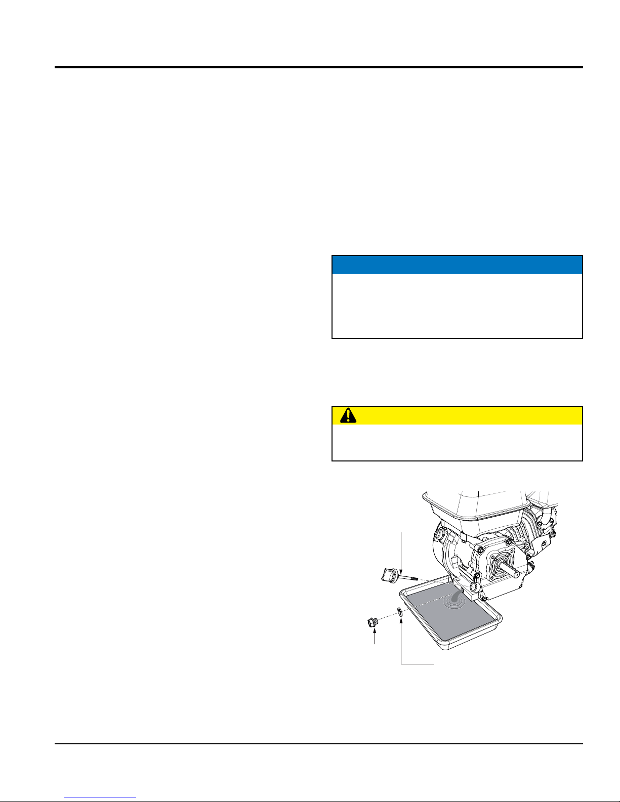
ENGINE OIL CHANGE
Drain the used oil while the engine is warm by the following:
Refer to Figure 23.
1. Place an oil pan or suitable container below the engine
drain bolt to catch the used oil.
2. Remove the filler cap/dipstick, drain bolt, and sealing
washer.
3. Drain the oil completely and reinstall the drain bolt and
sealing washer. Make sure the drain bolt is tightened
securely.
NOTICE
Dispose of used oil properly. DO NOT pour used oil on
the ground, down a drain, or throw in the trash. Used
oil can generally be taken to your local recycling center
or service station for reclamation.
4. Make sure the engine is in a level position and fill to the
outer edge of the oil filler hole with the recommended
oil (See Table 6). Engine oil capacity is 0.63 US quart
(0.60 liter).
CAUTION
BLADE SHAFT BEARINGS LUBRICATION
Regular lubrication of various components of the SP1G
Saw is critical to ensure a reasonable service life.
Two zerk fittings are located at the lower-front area of
the saw. Lubricate before daily use. Use a good quality
automotive or general purpose grease. Check and lubricate
more often if unit is under heavy use. Do not overfill
bearings. Overfilling can damage the grease seals which
can result in bearing exposure to dirt and contaminants
which can then shorten the life of the bearings. Excess
grease can also drip onto the cutting surface.
Running the engine with a low oil level can cause
engine damage.
5. Screw in the filler cap/dipstick securely.
OIL FILLER
DIPSTICK
DRAIN
BOLT
Figure 23. Engine Oil Change
SEALING
SP1G CONCRETE SAW • OPERATION MANUAL — REV. #3 (09/07/17) — PAGE 29
Page 30

Symptom Possible Problem Solution
shaft. Ensure the blade fl anges are clean and free
Blade slows or Stops cutting,still remains on
blade.
Blade does not cut straight and/or true.
Blade discoloring, crackling and/or wearing
excessively.
TROUBLESHOOTING
Troubleshooting (Blades)
Blade too hard for the material being
cut?
Engine Torgue diminished because of
loose V-Belts?
Insuffi cent Engine power? Check Throttle setting. Check Engine horespower.
Improper direction of rotation?
Blade is slipping on the blade shaft?
Blade being used on misaligned saw?
Blade is excessively hard for the material
being cut?
Blade being used at improper RPM?
Blade improperly mounted on arbor
shoulders and fl anges?
Excessive force applied to blade while
cutting?
Blade too hard for the material being
cut?
Blade improperly mounted on arbor
shoulders and fl anges?
Abor hole out of round?
Incorrect blade chosen for material being
cut?
Excessive force applied to blade while
cutting?
Consult Dealer or Multiquip for correct blade. Try
cutting very soft material (sandstone, silica brick,
cinder block) to "Redress" the blade.
Tighten and/or replace V-Belts.
Check that the blade is oriented and rotational
arrow points are in a "Down-Cutting" direction.
Check that the blade and fl ange pin are properly
installed on the blade shaft.
Check blade shaft bearings and alignment
integrity.
Check specifi cations of the blade with the
material being cut. Consult Dealer or Multiquip for
information.
Ensure blade surface feet per minute speed
(SFPM) is approximately 6,000.
Ensure blade is properly affi xed on the blade
shaft.
Do not force the blade in the cut. Apply a slow,
steady pace to sawing.
Consult Dealer or Multiquip for correct blade. Try
cutting very soft material (sandstone, silica brick,
cinder block) to"Redress" the blade.
Ensure blade is properly affi xed on the blade
of debris.
Ensure blade is properly affi xed on the blade
shaft.
Check specifi cations of the blade with the
material being cut. Consult Dealer or Multiquip for
information.
Do not force the blade in the cut. Apply a slow,
steady pace to sawing.
PAGE 30 — SP1G CONCRETE SAW • OPERATION MANUAL — REV. #3 (09/07/17)
Page 31
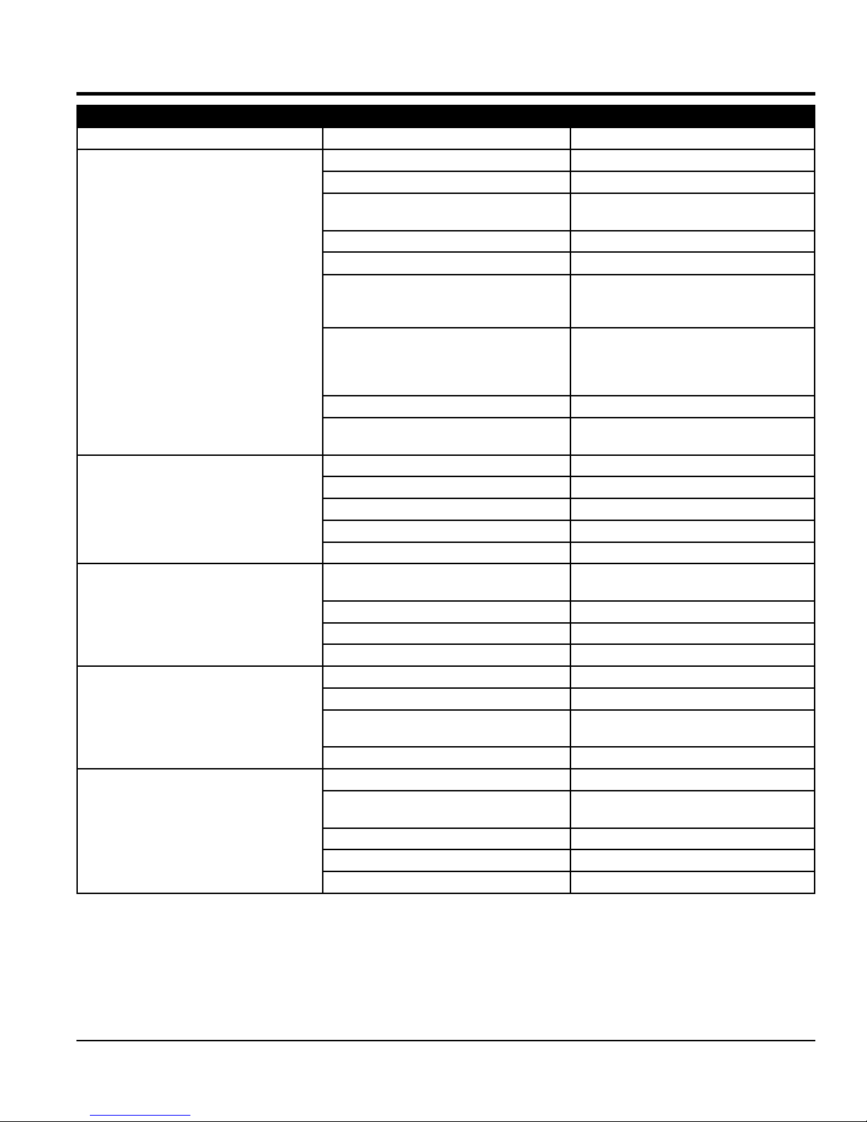
Symptom Possible Problem Solution
Diffi cult to start, fuel is available, but no spark at
spark plug.
Diffi cult to start, fuel is available, and spark is
present at the spark plug.
Diffi cult to start, fuel is available, spark is
present and compression is normal.
Diffi cult to start, fuel is available, spark is
present and compression is low.
No fuel present at carburetor.
TROUBLESHOOTING
Troubleshooting (Engine)
Spark plug bridging? Check gap, insulation or replace spark plug.
Carbon deposit on spark plug? Clean or replace spark plug.
Short circuit due to defi cient spark plug
insulation?
Improper spark plug gap? Set to proper gap.
Spark plug is red? Check transistor ignition unit.
Spark plug is bluish white?
No spark present at tip of spark plug?
No oil? Add oil as required.
Oil pressure alarm lamp blinks upon starting? (if
applicable)
ON/OFF switch is shorted? Check switch wiring, replace switch.
Ignition coil defective? Replace ignition coil.
Improper spark gap, points dirty? Set correct spark gap and clean points.
Condenser insulation worn or short circuiting? Replace condenser.
Spark plug wire broken or short circuiting? Replace defective spark plug wiring.
Wrong fuel type?
Water or dust in fuel system? Flush fuel system.
Air cleaner dirty? Clean or replace air cleaner.
Choke open? Close choke.
Suction/exhaust valve stuck or protruded? Reseat valves.
Piston ring and/or cylinder worn? Replace piston rings and/or piston.
Cylinder head and/or spark plug not tightened
properly?
Head gasket and/or spark plug gasket damaged? Replace head and spark plug gaskets.
No fuel in fuel tank? Fill with correct type of fuel.
Fuel cock does not open properly?
Fuel fi lter/lines clogged? Replace fuel fi lter.
Fuel tank cap breather hole clogged? Clean or replace fuel tank cap.
Air in fuel line? Bleed fuel line.
Check spark plug insulation, replace if worn.
If insuffi cient compression, repair or replace
engine. If injected air leaking, correct leak. If
carburetor jets clogged, clean carburetor.
Check transistor ignition unit is broken, and
replace defective unit. Check if voltage cord
cracked or broken and replace. Check if spark
plug if fouled and replace.
Check automatic shutdown circuit, "oil sensor".
(if applicable)
Flush fuel system, replace with correct type of
fuel.
Torque cylinder head bolts and spark plug.
Apply lubricant to loosen fuel cock lever,
replace if necessary.
SP1G CONCRETE SAW • OPERATION MANUAL — REV. #3 (09/07/17) — PAGE 31
Page 32

Symptom Possible Problem Solution
Weak in power, compression is proper and
does not misfi re.
Weak in power, compression is proper but
misfi res.
Engine overheats
Rotational speed fl uctuates.
Recoil starter malfunctions. (if applicable)
Starter malfunctions.
Burns too much fuel.
Exhaust color is continuously "white".
Exhaust color is continuously "black".
Will not start, no power with key "ON". (if
applicable)
TROUBLESHOOTING
Troubleshooting (Engine) - continued
Air cleaner dirty? Clean or replace air cleaner.
Improper level in carburetor? Check fl oat adjustment, rebuild carburetor.
Defective spark plug? Clean or replace spark plug.
Improper spark plug? Set to proper gap.
Water in fuel system?
Dirty spark plug? Clean or replace spark plug.
Ignition coil defective? Replace ignition coil.
Wrong type of fuel? Replace with correct type of fuel.
Cooling fi ns dirty? Clean cooling fi ns.
Intake air restricted?
Oil level too low or too high? Adjust oil to proper level.
Governor adjusted incorrectly? Adjust governor.
Governor spring defective? Replace governor spring.
Fuel fl ow restricted? Check entire fuel system for leaks or clogs.
Recoil mechanism clogged with dust and dirt? Clean recoil assembly with soap and water.
Spiral spring loose? Replace spiral spring.
Loose, damaged wiring?
Battery insuffi ciently charged? Recharge or replace battery.
Starter damaged or internally shorted? Replace starter.
Over-accumulation of exhaust products?
Wrong spark plug?
Lubricating oil is wrong viscosity? Replace lubricating oil with correct viscosity.
Worn rings? Replace rings.
Air cleaner clogged? Clean or replace air cleaner.
Choke valve set to incorrect position? Adjust choke valve to correct position.
Carburetor defective, seal on carburetor
broken?
Poor carburetor adjustment, engine runs too
rich?
ON/OFF device not activated ON? Turn on ON/OFF device.
Battery disconnected or discharged?
Ignition switch/wiring defective? Replace ignition switch. Check wiring.
Flush fuel system and replace with correct
type of fuel.
Clear intake of dirt and debris. Replace air
cleaner elements as necessary.
Ensure tight, clean connections on battery
and starter.
Check and clean valves. Check muffl er and
replace if necessary.
Replace spark plug with manufacturer's
suggested type.
Replace carburetor or seal.
Adjust carburetor.
Check cable connections. Charge or replace
battery
PAGE 32 — SP1G CONCRETE SAW • OPERATION MANUAL — REV. #3 (09/07/17)
Page 33

NOTES
SP1G CONCRETE SAW • OPERATION MANUAL — REV. #3 (09/07/17) — PAGE 33
Page 34

OPERATION MANUAL
HERE’S HOW TO GET HELP
© COPYRIGHT 2017, MULTIQUIP INC.
Multiquip Inc
the MQ logo are registered trademarks of Multiquip Inc. and may not be used, reproduced, or altered without written permission. All other trademarks are the property
of their respective owners and used with permission.
This manual
The information and specifi cations included in this publication were in effect at the time of approval for printing. Illustrations, descriptions, references and technical data contained in
this manual are for guidance only and may not be considered as binding. Multiquip Inc. reserves the right to discontinue or change specifi cations, design or the information published
in this publication at any time without notice and without incurring any obligations.
PLEASE HAVE THE MODEL AND SERIAL
NUMBER ON-HAND WHEN CALLING
UNITED STATES
Multiquip Corporate Offi ce MQ Parts Department
18910 Wilmington Ave.
Carson, CA 90746
Contact : [email protected]
Service Department Warranty Department
800-421-1244
310-537-3700
Technical Assistance
800-478-1244 Fax: 310-943-2238
CANADA
Multiquip Multiquip (UK) Limited Head Offi ce
4110 Industriel Boul.
Laval, Quebec, Canada H7L 6V3
Contact : [email protected]
Tel. (800) 421-1244
Fax (310) 537-3927
Fax: 310-537-4259 800-421-1244
PN: 38641
Tel: (450) 625-2244
Tel: (877) 963-4411
Fax: (450) 625-8664
800-427-1244
310-537-3700
310-537-3700
UNITED KINGDOM
Unit 2, Northpoint Industrial Estate,
Globe Lane,
Dukinfi eld, Cheshire SK16 4UJ
Contact : [email protected]
Fax: 800-672-7877
Fax: 310-637-3284
Fax: 310-943-2249
Tel: 0161 339 2223
Fax: 0161 339 3226
,
MUST accompany the equipment at all times. This manual is considered a permanent part of the equipment and should remain with the unit if resold.
Your Local Dealer is:
PN: 38641
 Loading...