

MPS R00D Installation And Operating Instructions Manual
Model Number R00D
Dual Air Pressure Booster System • Installation and Operating Instructions
MPS
M I DW EST
PRESSURE
SY ST E M S
MPS
M I DW E ST
PRESSURE
SY S T EM S
1-1/2" Square
2" Square
A
A
C
B
1
1
2
334
4
2
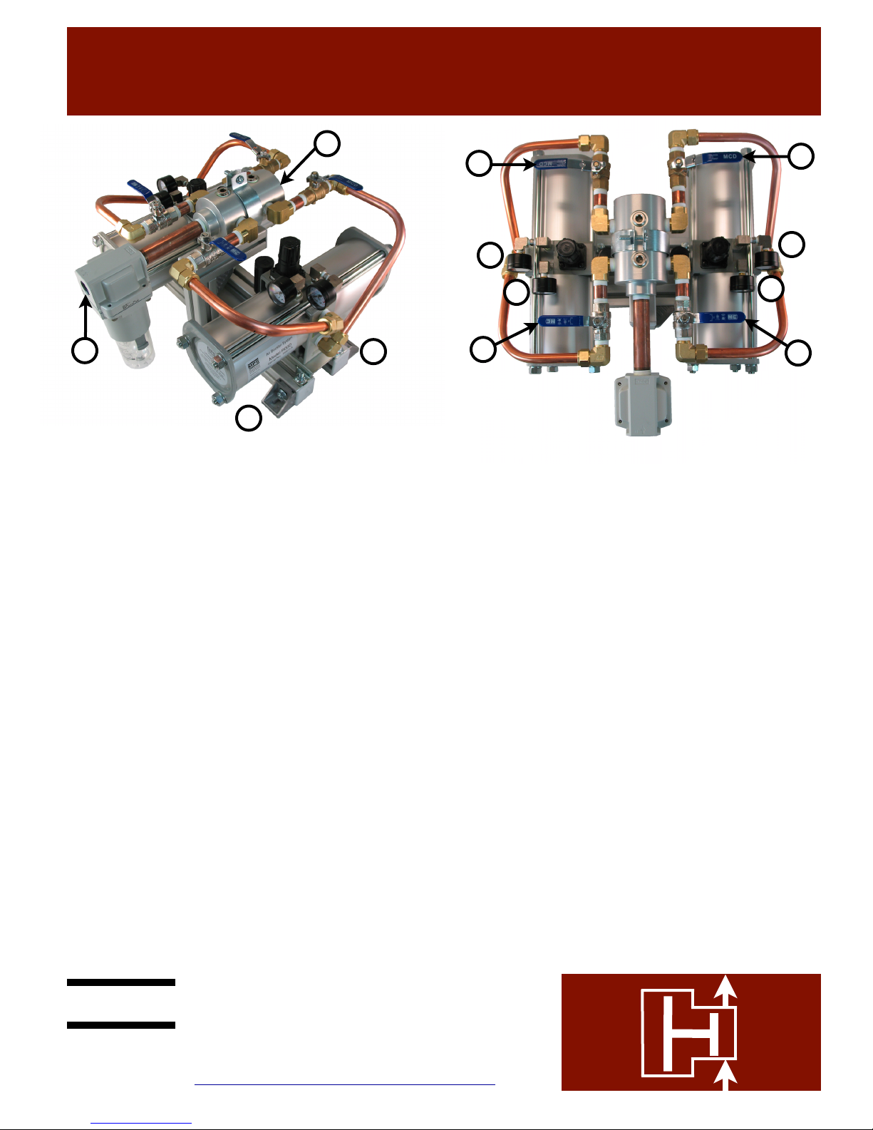
Installation
Bolt the assembly to the floor using the four mounting brackets
located on each corner of the system (A). The mounting pattern
is a 7.5” x 16.3” rectangle. Mounting screws can be up to 7/16
of an inch in diameter.
Connect the drive air supply to the 3/4 inch FNPT 5 micron
inlet filter (B). The air supply piping should be 3/4 inch pipe
diameter or larger.
Connect the discharge line to the 1 inch FNPT pipe port located
on the back of the system (C). The discharge piping should be
3/4 inch pipe diameter or larger.
WARNING: Make sure that the discharge piping
components are rated for 230 psi. If the discharge piping
has a lower pressure rating it should be protected by a
safety relief valve.
Startup
This booster can be operated with one or both boosters. To
operate with both boosters, open the inlet valves (1) and
discharge valves (2). To operate with one booster, close the
inlet valve and discharge valve of the desired booster.
There is a discharge pressure regulator for each of booster. Pull
up on the black knob on the top of the booster to unlock it. Turn
the knob to increase or decrease the desired discharge pressure.
The regulators are self-relieving. If one is set for a higher
pressure, the other regulator will try to vent the pressure. When
both boosters are operating at the same time, the regulators
must be set to the same pressure. The location of the
pressure gauges (3) and the discharge pressure gauges (4) are
shown above. When the boosters have pressurized the
downstream components to the maximum desired pressure,
they will stall. If one of the self-relieving regulators vents at
the stall condition, turn the knob clockwise until the venting
stops. The maximum recommended discharge pressure is 230
psi. If the supply pressure is higher than 115 psi, it is possible
to set the regulators so the system exceeds the maximum
discharge pressure of 230 psi. During startup, do not turn the
regulators to their highest setting, but slowly increase the
regulator settings until the desired pressure is reached.
WARNING: Do not exceed the maximum allowable
discharge pressure of 230 psi.
Operation
The system is fully automatic. When the desired discharge
pressure has been reached, and no flow is required, the
boosters will stop automatically. They will restart when the
discharge pressure drops about 5 psi.
Maintenance
The air supply filter should be checked periodically. If a
booster needs to be removed for service, close the air supply
valve and the discharge valve. The discharge valve will vent
the pressure between the two valves and the booster pressure
gauges should both read zero. The idle booster can be safely
removed and repaired while the other booster continues to
operate.
Midwest Pressure Systems, Inc.
850 Transport Drive, Valparaiso, IN 46383
Phone 219-462-0070 Fax 219-318-2277
www.midwestpressuresystems.com

Model Number R00D
Bootstrap Compressor • Operation and Warranty
MPS
M I DW EST
PRESSURE
SY ST E M S
MPS
M I DW E ST
PRESSURE
SY S T EM S
1-1/2" Square
2" Square
Compression
Chamber A1
Compression
Chamber A2
Drive
Chamber
B2
Drive
Chamber
B1
Piston 1
Piston 2
4-way
Valve
Switch
4-way
Valve
Switch
Pilot Signal to regulator
Built-in discharge regulator
Regulated drive air
Plant air
Exhaust air
Pilot signal to regulator
High pressure air
Exhaust air
Regulated drive air
Please refer to the operating description on the right, and the
schematic above to gain an understanding of the design principles
and mechanical function of the model R00D Booster System. The
moving parts of each Bootstrap Compressor are permanently
lubricated with a multipurpose grease (except for the check valves).
Operation with a lubricator upstream voids the warranty. If a
lubricator is required, it should be installed on the downstream
(discharge) side. A well-maintained 5 micron inlet air filter is
required to maintain the warranty by ensuring that no dust particles
enter the units and foul the seals, or cause premature wear of the
highly-polished seal surfaces. The wear parts in the boosters consist
of check valves, springs and dynamic seals. These parts are
designed for 1800 miles of piston travel. The four-way valve, which
controls movement of the pistons, is a lapped, stainless steel valve
with no elastomeric seals subject to wear. Under normal conditions,
this valve will provide many years of operation. The discharge
regulator built into the center of the unit sees very little wear, and is
designed to provide many years of service under normal conditions.
The wear parts are typically replaced 2 to 3 times before a valve or
regulator kit is required.
#KRW • Wear parts kit
#KRV • Valve kit
#KRR • Regulator kit
The plant air stream always fills Compression Chambers A1 and A2
directly, through a set of check valves. These two chambers are
always pressurized to the maximum initial air pressure available
(the R00D Booster System is not designed for inlet air pressures
higher than 150 psig). A branch of the plant air stream flows through
a pilot-activated regulator, which reduces the pressure to the level
required to attain the desired Bootstrap Compressor discharge
pressure (the discharge pressure is set manually by adjusting the
regulator handle). This regulated air stream flows through a fourway valve which directs it to Drive Chamber B2. At the same time,
the four-way valve opens Drive Chamber B1 to exhaust. The
pressure force exerted on the interconnected pistons by the
pressures in Drive Chamber B2 and Compression Chamber A1, is
sufficient to compress the air in Chamber A2 to a higher pressure
(the maximum discharge pressure attainable is two times the plant
air pressure). At the end of its travel, Piston 2 switches the four way
valve, which opens Drive Chamber B2 to exhaust, and pressurizes
Drive Chamber B1 with regulated drive air, thus reversing the
direction of the interconnected pistons, until Piston 1 switches the
valve back to its original position. The interconnected pistons shuttle
back and forth continuously, producing a high pressure air stream,
determined by the discharge pressure set on the built-in regulator.
The R00D Booster System is designed to operate at a maximum
discharge pressure of 230 psig. Higher discharge pressures, though
possible, can result in catastrophic failure of the booster.
Operating Description
General Concerns
Midwest Pressure Systems, Inc. warrants the R00D Booster System to be free of defects in material and workmanship for a period of
one year after purchase, except piston seals, rod seals, and check valves which are warranted for six months after purchase. We will
either repair or replace a failed unit returned by the customer. No other warranty is expressed or implied. Proof of the purchase date is
required. This warranty does not apply to equipment which has been abused, and is voided by use of a lubricator, or failure to use a
well-maintained inlet filter. Customer must obtain a return authorization number before shipping the unit to the factory.
WARRANTY
04/07/15
Midwest Pressure Systems, Inc.
850 Transport Drive, Valparaiso, IN 46383
Phone 219-462-0070 Fax 219-318-2277
www.midwestpressuresystems.com
 Loading...