

Page 1
MP1591
The Future of Analog IC Technology
DESCRIPTION
The MP1591 is a high voltage step-down
converter ideal for automotive power adapter
battery chargers. Its wide 6.5V to 32V input
voltage range covers the automotive battery’s
requirements and it achieves 2A continuous
output for quick charge capability.
Current mode operation provides fast transient
response and eases loop stabilization. Fault
protection includes cycle-by-cycle current
limiting and thermal shutdown. In shutdown
mode, the converter draws only 20A of supply
current.
The MP1591 requires a minimum number of
readily available external components to
complete a 2A step-down DC to DC converter
solution.
EVALUATION BOARD REFERENCE
Board Number Dimensions
EV0020 2.1”X x 1.4”Y x 0.5”Z
2A, 32V, 330KHz
Step-Down Converter
FEATURES
• Wide 6.5V to 32V Input Operating Range
• 34V Absolute Maximum Input
• 2A Output Current
• 120m Internal Power MOSFET Switch
• Stable with Low ESR Output Ceramic
Capacitors
• Up to 95% Efficiency
• 20A Shutdown Mode
• Fixed 330KHz Frequency
• Thermal Shutdown
• Cycle-by-Cycle Over Current Protection
• Output Adjustable From 1.23V to 21V
• Under Voltage Lockout
• Reference Voltage Output
• Available in 8-Pin SOIC Packages
APPLICATIONS
• Automotive Power Adapters
• PDA and Cellular Phone Battery Chargers
• Distributed Power Systems
• Automotive Aftermarket Electronics
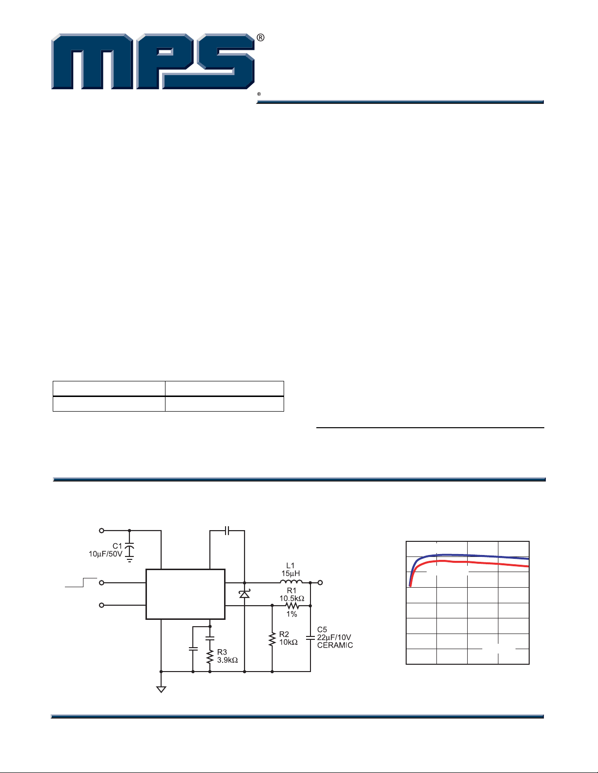
TYPICAL APPLICATION
INPUT
6.5V to 32V
2
7
OFF ON
OPEN
NOT USED
EN
8
MP1591
REF
GND COMP
4
C3
OPEN
BSIN
1
SW
FB
6
C4
4.7nF
C2
10nF
3
5
D1
“MPS” and “The Future of Analog IC Technology” are Registered Trademarks of
Monolithic Power Systems, Inc.
Efficiency vs
Load Current
100
V
=5V
OUT
90
V
=3.3V
OUTPUT
2.5V
2A
80
70
60
50
EFFICIENCY (%)
40
30
20
0 0.5 1 1.5 2
OUT
VIN=12V
LOAD CURRENT (A)
MP1591 Rev. 2.3 www.MonolithicPower.com 1
9/21/2007 MPS Proprietary Information. Unauthorized Photocopy and Duplication Prohibited.
© 2007 MPS. All Rights Reserved.
Page 2
MP1591 – 2A, 32V, 330KHz STEP-DOWN CONVERTER
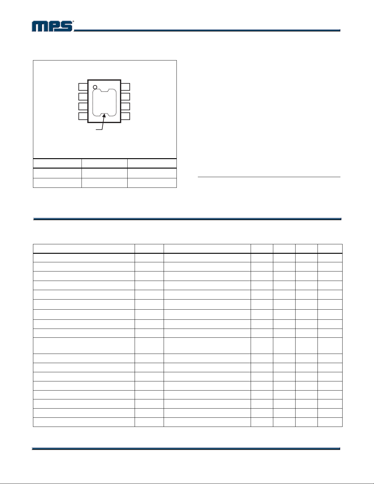
PACKAGE REFERENCE
TOP VIEW
BS
1
IN
2
SW
3
GND
4
EXPOSED PAD
ON BACKSIDE
(SOIC8N ONLY)
CONNECT TO PIN 4
Part Number* Package Temperature
MP1591DN SOIC8E
MP1591DS SOIC8
For Tape & Reel, add suffix –Z (eg. MP1591DN–Z)
*
For RoHS Compliant Packaging, add suffix –LF
(eg. MP1591DN–LF–Z)
REF
8
EN
7
COMP
6
FB
5
–40°C to +85°C
–40°C to +85°C
ABSOLUTE MAXIMUM RATINGS
(1)
IN Supply Voltage........................ –0.3V to +34V
SW Voltage............................. –1V to V
BS Voltage
....................VSW – 0.3V to VSW + 6V
+ 0.3V
IN
All Other Pins................................. –0.3V to +6V
Junction Temperature............................... 150°C
Lead Temperature .................................... 260°C
Storage Temperature ..............–65°C to +150°C
Recommended Operating Conditions
(2)
Input Voltage ................................... 6.5V to 32V
Operating Temperature .............–40°C to +85°C
Thermal Resistance
(3)
θ
JA
θJC
SOIC8 (w/ Exposed Pad) ....... 50 ...... 10... °C/W
SOIC8..................................... 90 ...... 45... °C/W
Notes:
1) Exceeding these ratings may damage the device.
2) The device is not guaranteed to function outside of its
operating conditions.
3) Measured on approximately 1” square of 1 oz copper.
ELECTRICAL CHARACTERISTICS
VIN = 12V, TA = +25°C, unless otherwise noted.
Parameter Symbol Condition Min Typ Max Units
Shutdown Supply Current VEN = 0V 20 35 A
Supply Current VEN = 5V, VFB = 1.4V 1.0 1.2 mA
Feedback Voltage
6.5V ≤ V
≤ 32V, V
IN
COMP
< 2V
Error Amplifier Voltage Gain 400 V/V
Error Amplifier Transconductance
High-Side Switch On Resistance
Low-Side Switch On Resistance
(4)
120
(4)
8.5
ΔI
= ±10A
C
High-Side Switch Leakage Current VEN = 0V, VSW = 0V 0 10 A
Current Limit
Current Sense to COMP
Transconductance
(5)
2.5 3.6 4.9 A
3.5 A/V
Oscillation Frequency 280 330 380 KHz
Short Circuit Oscillation Frequency VFB = 0V 35 KHz
Maximum Duty Cycle
Minimum Duty Cycle
(4)
V
(4)
V
= 1.0V 90 %
FB
= 1.5V 0 %
FB
EN Shutdown Threshold Voltage 0.8 1.2 1.6 V
Enable Pull-Up Current VEN = 0V 1.8 A
EN UVLO Threshold VEN Rising 2.4 2.6 2.8 V
EN UVLO Threshold Hysteresis 250 mV
1.202 1.230 1.258 V
500 700 1100 A/V
mΩ
Ω
MP1591 Rev. 2.3 www.MonolithicPower.com 2
9/21/2007 MPS Proprietary Information. Unauthorized Photocopy and Duplication Prohibited.
© 2007 MPS. All Rights Reserved.
Page 3
MP1591 – 2A, 32V, 330KHz STEP-DOWN CONVERTER
ELECTRICAL CHARACTERISTICS (continued)
VIN = 12V, TA = +25°C, unless otherwise noted.
Parameter Symbol Condition Min Typ Max Units
Thermal Shutdown
REF Voltage I
REF Load Regulation
REF Line Regulation
Notes:
4) These parameters are guaranteed by design, not production tested.
5) Equivalent output current = 1.5A 50% Duty Cycle
2.0A 50% Duty Cycle
Assumes ripple current = 30% of load current.
Slope compensation changes current limit.
(4)
160
= 0 5.0 V
(4)
I
(4)
I
REF
= 0 to 1mA 100 mV
REF
= 100A, VIN = 6.5 to 32V 30 mV
REF
°C
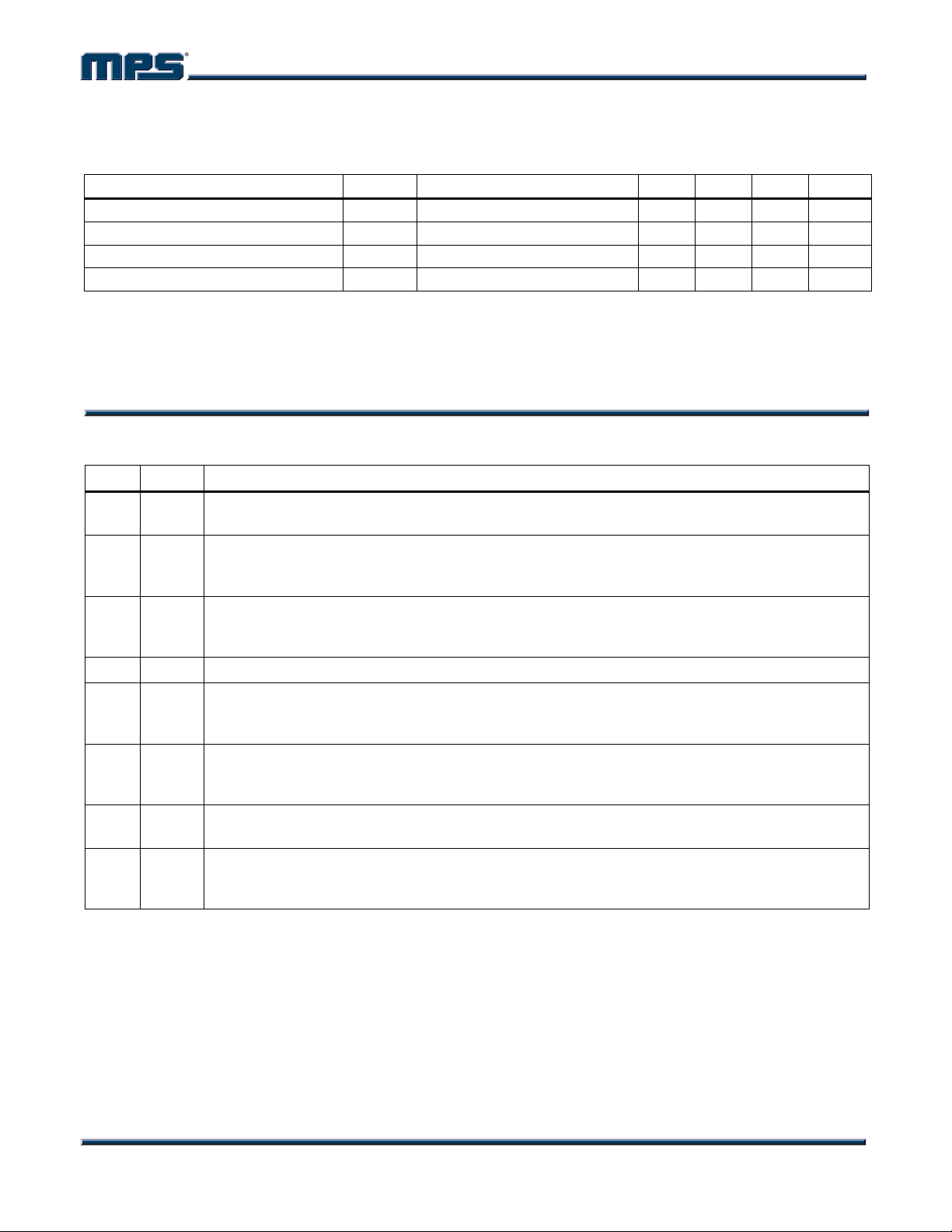
PIN FUNCTIONS
Pin # Name Description
1 BS High-Side Gate Drive Boost Input. BS supplies the drive for the high-side N-Channel MOSFET
switch. Connect a 10nF or greater capacitor from SW to BS to power the high-side switch.
2 IN Power Input. IN supplies the power to the IC, as well as the step-down converter switches.
Drive IN with a 6.5V to 32V power source. Bypass IN to GND with a suitably large capacitor to
eliminate noise on the input to the IC. See Input Capacitor.
3 SW Power Switching Output. SW is the switching node that supplies power to the output. Connect
the output LC filter from SW to the output load. Note that a capacitor is required from SW to BS
to power the high-side switch.
4 GND Ground. For the MP1591DN, connect the Exposed Pad to pin 4.
5 FB Feedback Input. FB senses the output voltage to regulate that voltage. Drive FB with a resistive
voltage divider from the output voltage. The feedback threshold is 1.230V. See Setting the
Output Voltage.
6 COMP Compensation Node. COMP is used to compensate the regulation control loop. Connect a
series RC network from COMP to GND to compensate the regulation control loop. In some
cases, an additional capacitor from COMP to GND is required. See Compensation.
7 EN Enable/UVLO. A voltage greater than 2.8V enables operation. For complete low current
shutdown the EN pin voltage needs to be less than 800mV.
8 REF Reference Output. REF is the 5V reference voltage output. It can supply up to 1mA to external
circuitry. If used, bypass REF to GND with 10nF or greater capacitor. Leave REF unconnected
if not used.
MP1591 Rev. 2.3 www.MonolithicPower.com 3
9/21/2007 MPS Proprietary Information. Unauthorized Photocopy and Duplication Prohibited.
© 2007 MPS. All Rights Reserved.
Page 4
MP1591 – 2A, 32V, 330KHz STEP-DOWN CONVERTER
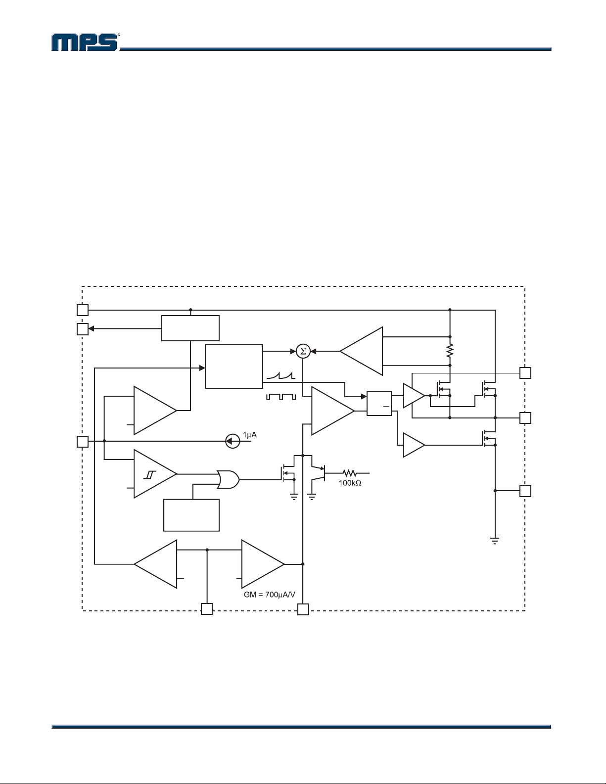
OPERATION
The MP1591 is a current mode step-down
regulator. It regulates input voltages from 6.5V
to 32V down to an output voltage as low as
1.230V and is able to supply up to 2A of load
current.
The MP1591 uses current-mode control to
regulate the output voltage. The output voltage
is measured at FB through a resistive voltage
divider and amplified through the internal error
amplifier. The output current of the
transconductance error amplifier is presented at
COMP where a network compensates the
regulation control system.
2
IN
5V
REF
EN
8
+
--
1.2V
7
--
2.60V/
2.35V
+
INTERNAL
REGULATORS
SHUTDOWN
COMPARATOR
LOCKOUT
COMPARATOR
OSCILLATOR
35/330KHz
SLOPE
COMP
CLK
The voltage at COMP is compared to the switch
current measured internally to control the output
voltage. The converter uses an internal
N-Channel MOSFET switch to step-down the
input voltage to the regulated output voltage.
Since the MOSFET requires a gate voltage
greater than the input voltage, a boost capacitor
connected between SW and BS drives the gate.
The capacitor is internally charged while SW is
low. An internal 10 switch from SW to GND is
used to insure that SW is pulled to GND when
the switch is off to fully charge the BS capacitor
CURRENT
SENSE
AMPLIFIER
+
CURRENT
-COMPARATOR
+
--
SRQ
1.8V
1
M1
Q
3
M2
4
BS
SW
GND
THERMAL
PROTECTION
ERROR
AMPLIFIER
--
+
6
COMP
FREQUENCY
FOLDBACK
COMPARATOR
+
--
1.230V0.7V
5
FB
Figure 1—Functional Block Diagram
MP1591 Rev. 2.3 www.MonolithicPower.com 4
9/21/2007 MPS Proprietary Information. Unauthorized Photocopy and Duplication Prohibited.
© 2007 MPS. All Rights Reserved.
Page 5
MP1591 – 2A, 32V, 330KHz STEP-DOWN CONVERTER
APPLICATION INFORMATION
COMPONENT SELECTION
Setting the Output Voltage
The output voltage is set using a resistive
voltage divider from the output voltage to FB.
The voltage divider divides the output voltage
down by the ratio:
2R
×=
VV
OUTFB
Where V
is the feedback voltage and V
FB
the output voltage.
Thus the output voltage is:
×=
OUT
230.1V
A typical value for R2 can be as high as 100k,
but 10k is recommended. Using that value, R1
is determined by:
−×≅
OUT
For example, for a 3.3V output voltage, R2 is
10k, and R1 is 17k.
Inductor (L1)
The inductor is required to supply constant
current to the output load while being driven by
the switched input voltage. A larger value
inductor results in less ripple current that results
in lower output ripple voltage. However, the
larger value inductor has a larger physical size,
higher series resistance, and/or lower
saturation current. Choose an inductor that
does not saturate under the worst-case load
conditions. A good rule to use for determining
the inductance is to allow the peak-to-peak
ripple current in the inductor to be
approximately 30% of the maximum load
current that the IC can provide. Also, make sure
that the peak inductor current (the load current
plus half the peak-to-peak inductor ripple
current) is below the 2.3A minimum current limit.
)2R1R(
+
is
OUT
+
)2R1R(
2R
)230.1V(18.81R
The inductance value can be calculated by the
equation:
)VV(
OUTIN
)IfV(
Δ××
Where V
V1L
OUT
is the input voltage, f is the switching
IN
−
×=
IN
frequency and I is the peak-to-peak inductor
ripple current.
Table 1 lists a number of suitable inductors
from various manufacturers.
Table 1—Inductor Selection Guide
Package
Dimensions
Vendor/
Model
Sumida
CR75 Open Ferrite 7.0 7.8 5.5
CDH74 Open Ferrite 7.3 8.0 5.2
CDRH5D28 Shielded Ferrite 5.5 5.7 5.5
CDRH5D28 Shielded Ferrite 5.5 5.7 5.5
CDRH6D28 Shielded Ferrite 6.7 6.7 3.0
CDRH104R Shielded Ferrite 10.1 10.0 3.0
Toko
D53LC
Type A
D75C Shielded Ferrite 7.6 7.6 5.1
D104C Shielded Ferrite 10.0 10.0 4.3
D10FL Open Ferrite 9.7 1.5 4.0
Coilcraft
DO3308 Open Ferrite 9.4 13.0 3.0
DO3316 Open Ferrite 9.4 13.0 5.1
Core
Type
Shielded Ferrite 5.0 5.0 3.0
Core
Material
(mm)
WL H
Input Capacitor (C1)
The input current to the step-down converter is
discontinuous, and so a capacitor is required to
supply the AC current to the step-down
converter while maintaining the DC input
voltage. A low ESR capacitor is required to
keep the noise at the IC to a minimum. Ceramic
capacitors are preferred, but tantalum or low
ESR electrolytic capacitors may also suffice.
MP1591 Rev. 2.3 www.MonolithicPower.com 5
9/21/2007 MPS Proprietary Information. Unauthorized Photocopy and Duplication Prohibited.
© 2007 MPS. All Rights Reserved.
Page 6
MP1591 – 2A, 32V, 330KHz STEP-DOWN CONVERTER
×
The input capacitor value should be greater
than 10F. The capacitor can be electrolytic,
tantalum or ceramic. However, since it absorbs
the input switching current it requires an
adequate ripple current rating. Its RMS current
rating should be greater than approximately 1/2
of the DC load current.
For insuring stable operation C1 should be
placed as close to the IC as possible.
Alternately, a smaller high quality ceramic
0.1F capacitor may be placed closer to the IC
and a larger capacitor placed farther away. If
using this technique, it is recommended that the
larger capacitor be a tantalum or electrolytic
type. All ceramic capacitors should be placed
close to the MP1591.
Output Capacitor (C5)
The output capacitor is required to maintain the
DC output voltage. Low ESR capacitors are
preferred to keep the output voltage ripple low.
The characteristics of the output capacitor also
affect the stability of the regulation control
system. Ceramic, tantalum or low ESR
electrolytic capacitors are recommended. In the
case of ceramic capacitors, the impedance at
the switching frequency is dominated by the
capacitance, and so the output voltage ripple is
mostly independent of the ESR. The output
voltage ripple is estimated to be:
2
⎞
⎛
f
LC
⎟
⎜
V4.1V
××≅
INRIPPLE
⎜
⎝
Where V
is the output ripple voltage, fLC is
RIPPLE
the resonant frequency of the LC filter, f
f
SW
⎟
⎠
is the
SW
switching frequency.
In the case of tantalum or low-ESR electrolytic
capacitors, the ESR dominates the impedance
at the switching frequency, and so the output
ripple is calculated as:
RIV
Δ≅
ESRRIPPLE
Output Rectifier Diode (D1)
The output rectifier diode supplies the current to
the inductor when the high-side switch is off. To
reduce losses due to the diode forward voltage
and recovery times, use a Schottky rectifier.
Table 2 provides some recommended Schottky
rectifiers based on the maximum input voltage
and current rating.
Table 2—Diode Selection Guide
V
IN
(Max)
15V 30BQ15 4
20V
30V
34V
2A Load Current 3A Load Current
Part
Number
B220 1 B320 1
SK23 6 SK33 1, 6
SR22 6 SS32 3
20BQ030 4 B330 1
B230 1 B340L 1
SK23 6 MBRD330 4, 5
SR23 3, 6 SK33 1, 6
SS23 2, 3 SS33 2, 3
21DQ04 4 B340L 1
MBRS240L 5 MBRS340 4
SK24 6 SK34 1, 6
SS24 2, 3 SS34 2, 3
Vendor
Part
Number
Vendor
Table 3 lists manufacturer’s websites.
Table 3—Schottky Diode Manufacturers
# Vendor Web Site
1 Diodes, Inc. www.diodes.com
2 Fairchild Semiconductor www.fairchildsemi.com
3 General Semiconductor www.gensemi.com
4 International Rectifier www.irf.com
5 On Semiconductor www.onsemi.com
6 Pan Jit International www.panjit.com.tw
Choose a rectifier whose maximum reverse
voltage rating is greater than the maximum
input voltage, and whose current rating is
greater than the maximum load current.
Where V
R
is the equivalent series resistance of the
ESR
is the output voltage ripple and
RIPPLE
output capacitors.
MP1591 Rev. 2.3 www.MonolithicPower.com 6
9/21/2007 MPS Proprietary Information. Unauthorized Photocopy and Duplication Prohibited.
© 2007 MPS. All Rights Reserved.
Page 7
MP1591 – 2A, 32V, 330KHz STEP-DOWN CONVERTER
Compensation
The system stability is controlled through the
COMP pin. COMP is the output of the internal
transconductance error amplifier. A series
capacitor-resistor combination sets a pole-zero
combination to control the characteristics of the
control system. The DC loop gain is:
V
A ×××=
VDC
Where V
REF
1.230V, A
REF
V
OUT
is the feedback threshold voltage,
is the transconductance error
VEA
amplifier voltage gain, 400 V/V, and G
RGA
LOADCSVEA
is the
CS
current sense gain (roughly the output current
divided by the voltage at COMP), 3.5 A/V.
The system has 2 poles of importance; one is
due to the compensation capacitor (C4) and the
other is due to the output capacitor (C5). These
are:
G
Where f
f
=
1P
is the first pole, and G
P1
MEA
VEA
)4CA2(
××π
is the error
MEA
amplifier transconductance (770S) and
f
=
2P
1
LOAD
)5CR2(
××π
The system has one zero of importance due to
the compensation capacitor (C4) and the
compensation resistor (R3) which is
f
=
1Z
1
)4C3R2(
××π
If large value capacitors with relatively high
equivalent-series-resistance (ESR) are used,
the zero due to the capacitance and ESR of the
output capacitor can be compensated by a third
pole set by R3 and C3
The system crossover frequency f
(the
C,
frequency where the loop gain drops to 1, or
0dB) is important. A good rule of thumb is to set
the crossover frequency to approximately one
tenth of the switching frequency. In this case,
the switching frequency is 330KHz, so use a
crossover frequency of 33KHz. Lower
crossover frequencies result in slower response
and worse transient load recovery. Higher
crossover frequencies can result in instability.
Choosing the Compensation Components
The values of the compensation components
given in Table 4 yield a stable control loop for
the output voltage and given capacitor.
Table 4—Compensation Values for Typical
Output Voltage/Capacitor Combinations
V
OUT
2.5V 22F Ceramic 3.9k None 4.7nF
3.3V 22F Ceramic 5.1k None 3.9nF
5V 22F Ceramic 7.5k None 2.7nF
12V 22F Ceramic 18k None 1.2nF
2.5V 47F SP-Cap 8.2k None 2.2nF
3.3V 47F SP-Cap 10k None 2.2nF
5V 47F SP-Cap 16k None 1.5nF
12V 47F SP-Cap 36k None 1nF
2.5V
3.3V
5V
12V
Note: “AL” = Electrolytic
C5 R3 C3 C4
560F/6.3V, AL
30m ESR
560F/6.3V, AL
30m ESR
470F/10V, AL
30m ESR
220F/25V, AL
30m ESR
100k 150pF 1nF
120k 120pF 1nF
150k 82pF 1nF
180k 33pF 1nF
f
=
3P
MP1591 Rev. 2.3 www.MonolithicPower.com 7
9/21/2007 MPS Proprietary Information. Unauthorized Photocopy and Duplication Prohibited.
© 2007 MPS. All Rights Reserved.
1
)3C3R2(
××π
Page 8
MP1591 – 2A, 32V, 330KHz STEP-DOWN CONVERTER
To optimize the compensation components that
are not listed in Table 4, use the following
procedure.
Choose the compensation resistor to set the
desired crossover frequency. Determine the
value by the following equation:
fV5C2
×××π
COUT
3R
=
××
VGG
REFCSEA
Putting in the know constants and setting the
crossover frequency to the desired 33KHz:
7
V5C1088.63R ×××≅
OUT
Choose the compensation capacitor to set the
zero below one fourth of the crossover
frequency. Determine the value by the following
equation:
5C−
4C
2
>
≈
f3R
××π
1093.1
×
3R
Determine if the second compensation
capacitor, C3, is required. It is required if the
ESR zero of the output capacitor occurs at less
than four times the crossover frequency, or
1fR5C8
≥×××π
CESR
If this is the case, then add the second
compensation resistor. Determine the value by
the equation:
×
=
R5C
3C
)MAX(ESR
3R
Example:
V
= 5V, C5 = 22F Ceramic (ESR = 10m)
OUT
7
R3 6.88x10
(22x10-6) (5) = 7568
Use the nearest standard value of 7.5k.
C4 > 1.93x10
-5
/ 7.5K = 2.57nF
Use standard value of 2.7nF.
8 x C5 x R
x fC = 0.22, which is less than 1.
ESR
Therefore, no second compensation capacitor
(C3) is required.
External Bootstrap Diode
It is recommended that an external bootstrap
diode be added when the system has a 5V
fixed input or the power supply generates a 5V
output. This helps improve the efficiency of the
regulator. The bootstrap diode can be a low
cost one such as IN4148 or BAT54.
5V
1
BS
MP1591
SW
10nF
3
Figure 2—External Bootstrap Diode
This diode is also recommended for high duty
V
OUT
cycle operation (when
output voltage (V
>12V) applications.
OUT
>65%) and high
V
IN
Where R
ESR(MAX)
is the maximum ESR of the
output capacitor.
MP1591 Rev. 2.3 www.MonolithicPower.com 8
9/21/2007 MPS Proprietary Information. Unauthorized Photocopy and Duplication Prohibited.
© 2007 MPS. All Rights Reserved.
Page 9
MP1591 – 2A, 32V, 330KHz STEP-DOWN CONVERTER
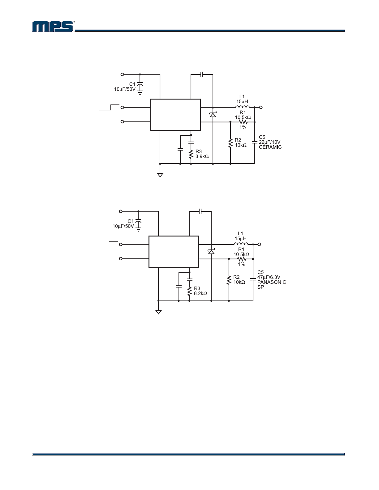
TYPICAL APPLICATION CIRCUITS
INPUT
6.5V to 32V
C2
10nF
OFF ON
OPEN
NOT USED
2
7
EN
8
MP1591
REF
GND COMP
4
C3
OPEN
BSIN
1
SW
FB
6
C4
4.7nF
3
D1
5
OUTPUT
2.5V
2A
Figure 3—MP1591 with Murata 22μF / 10V Ceramic Output Capacitor
C2
BSIN
1
SW
FB
6
C4
2.2nF
10nF
3
5
D1
OUTPUT
2.5V
2A
INPUT
6.5V to 32V
OFF ON
OPEN
NOT USED
2
7
EN
8
MP1591
REF
GND COMP
4
C3
OPEN
Figure 4—MP1591 with Panasonic 47μF / 6.3V Special Polymer Output Capacitor
MP1591 Rev. 2.3 www.MonolithicPower.com 9
9/21/2007 MPS Proprietary Information. Unauthorized Photocopy and Duplication Prohibited.
© 2007 MPS. All Rights Reserved.
Page 10
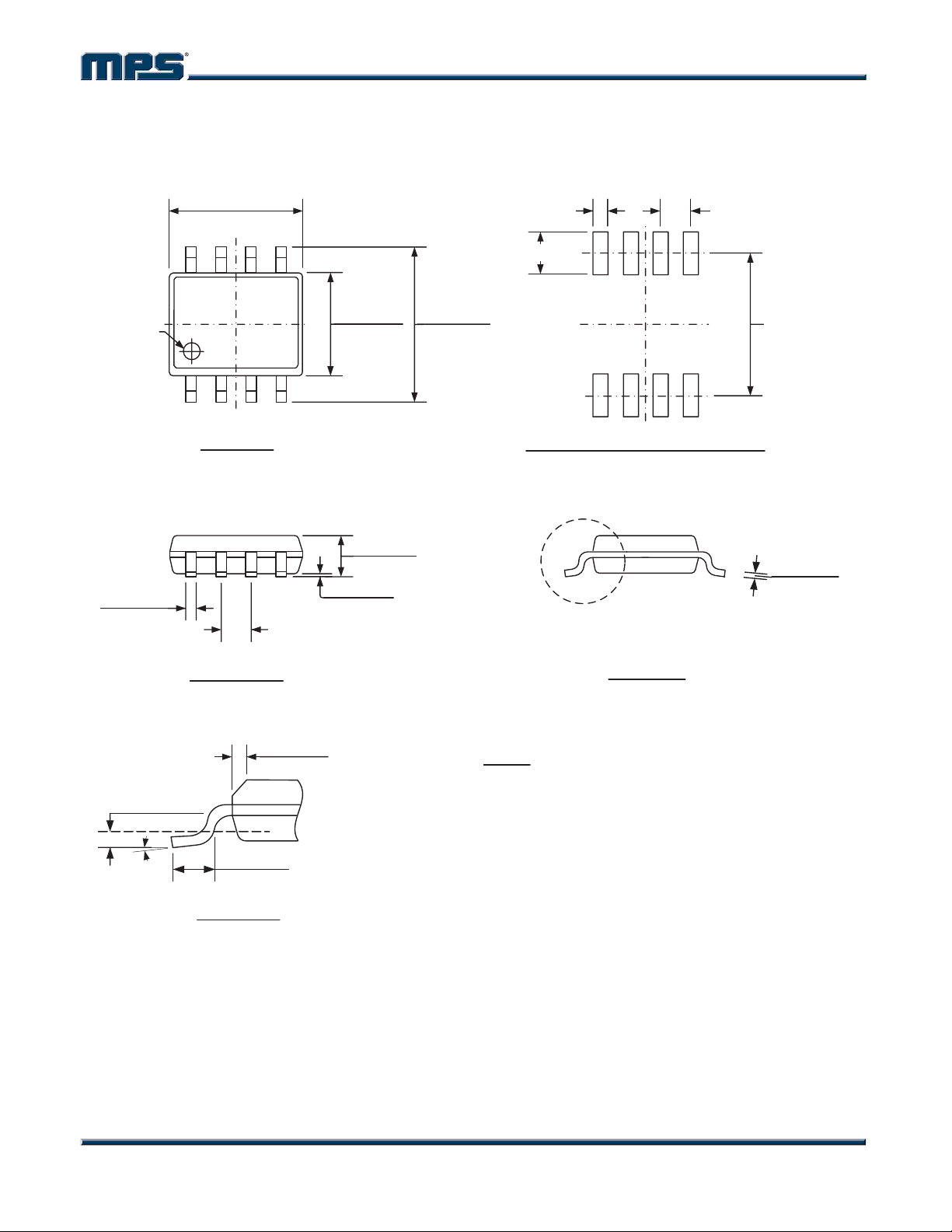
PACKAGE INFORMATION
0.189(4.80)
0.197(5.00)
85
MP1591 – 2A, 32V, 330KHz STEP-DOWN CONVERTER
SOIC8
0.024(0.61)
0.063(1.60)
0.050(1.27)
PIN 1 ID
0.013(0.33)
0.020(0.51)
GAUGE PLANE
0.010(0.25) BSC
o
0o-8
0.150(3.80)
0.157(4.00)
14
TOP VIEW
0.053(1.35)
0.069(1.75)
SEATING PLANE
0.004(0.10)
0.010(0.25)
0.050(1.27)
BSC
FRONT VIEW
0.010(0.25)
0.020(0.50)
0.016(0.41)
0.050(1.27)
x 45
o
DETAIL "A"
0.228(5.80)
0.244(6.20)
0.213(5.40)
RECOMMENDED LAND PATTERN
0.0075(0.19)
0.0098(0.25)
SEE DETAIL "A"
SIDE VIEW
NOTE:
1) CONTROL DIMENSION IS IN INCHES. DIMENSION IN
BRACKET IS IN MILLIMETERS.
2) PACKAGE LENGTH DOES NOT INCLUDE MOLD FLASH,
PROTRUSIONS OR GATE BURRS.
3) PACKAGE WIDTH DOES NOT INCLUDE INTERLEAD FLASH
OR PROTRUSIONS.
4) LEAD COPLANARITY (BOTTOM OF LEADS AFTER FORMING)
SHALL BE 0.004" INCHES MAX.
5) DRAWING CONFORMS TO JEDEC MS-012, VARIATION AA.
6) DRAWING IS NOT TO SCALE.
MP1591 Rev. 2.3 www.MonolithicPower.com 10
9/21/2007 MPS Proprietary Information. Unauthorized Photocopy and Duplication Prohibited.
© 2007 MPS. All Rights Reserved.
Page 11
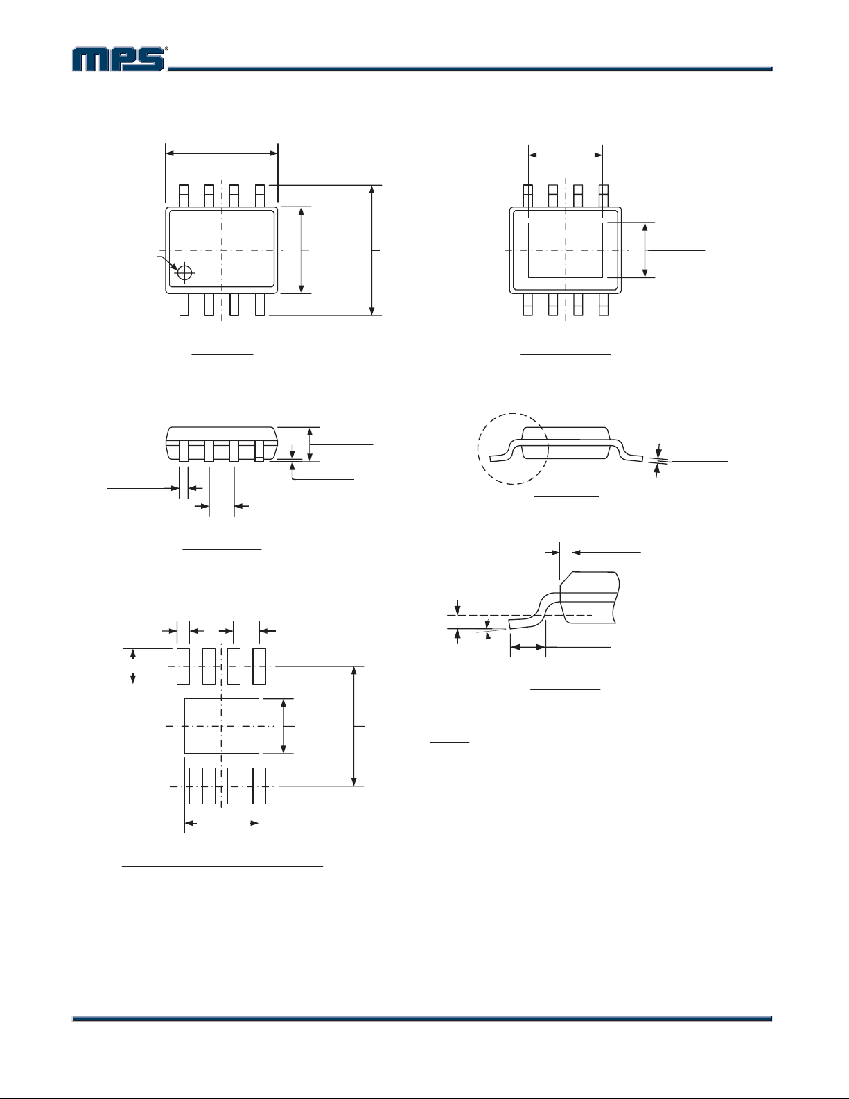
SOIC8E (WITH EXPOSED PAD)
0.189(4.80)
0.197(5.00)
85
MP1591 – 2A, 32V, 330KHz STEP-DOWN CONVERTER
0.124(3.15)
0.136(3.45)
PIN 1 ID
0.013(0.33)
0.020(0.51)
0.024(0.61)
0.063(1.60)
0.150(3.80)
0.157(4.00)
14
TOP VIEW
0.051(1.30)
0.067(1.70)
SEATING PLANE
0.000(0.00)
0.006(0.15)
0.050(1.27)
BSC
FRONT VIEW
0.050(1.27)
0.228(5.80)
0.244(6.20)
SEE DETAIL "A"
GAUGE PLANE
0.010(0.25) BSC
o
0o-8
BOTTOM VIEW
SIDE VIEW
0.010(0.25)
0.020(0.50)
0.016(0.41)
0.050(1.27)
DETAIL "A"
0.089(2.26)
0.101(2.56)
0.0075(0.19)
0.0098(0.25)
o
x 45
0.103(2.62)
0.213(5.40)
NOTE:
1) CONTROL DIMENSION IS IN INCHES. DIMENSION IN
BRACKET IS IN MILLIMETERS.
2) PACKAGE LENGTH DOES NOT INCLUDE MOLD FLASH,
PROTRUSIONS OR GATE BURRS.
3) PACKAGE WIDTH DOES NOT INCLUDE INTERLEAD FLASH
0.138(3.51)
RECOMMENDED LAND PATTERN
OR PROTRUSIONS.
4) LEAD COPLANARITY (BOTTOM OF LEADS AFTER FORMING)
SHALL BE 0.004" INCHES MAX.
5) DRAWING CONFORMS TO JEDEC MS-012, VARIATION BA.
6) DRAWING IS NOT TO SCALE.
NOTICE: The information in this document is subject to change without notice. Users should warrant and guarantee that third
party Intellectual Property rights are not infringed upon when integrating MPS products into any application. MPS will not
assume any legal responsibility for any said applications.
MP1591 Rev. 2.3 www.MonolithicPower.com 11
9/21/2007 MPS Proprietary Information. Unauthorized Photocopy and Duplication Prohibited.
© 2007 MPS. All Rights Reserved.
 Loading...