

Page 1

MPS I
2
C Interface User Manual
Revision 1.0
Monolithic Power Systems
www.monolithicpower.com
Page 2

TABLE OF CONTENTS – 目录
1. INTRODUCTION ....................................................................................................... 2
1.1 What is the MPS I2C GUI? ................................................................................................. 2
1.2 System Requirements ......................................................................................................... 2
2. INSTALLATION ........................................................................................................ 3
2.1 Installing the MPS IIC GUI .................................................................................................. 3
2.2 Installing the USB Driver ..................................................................................................... 3
3. USAGE ..................................................................................................................... 6
3.1 Hardware Connection ......................................................................................................... 6
3.2 Using the GUI ...................................................................................................................... 6
1
Page 3
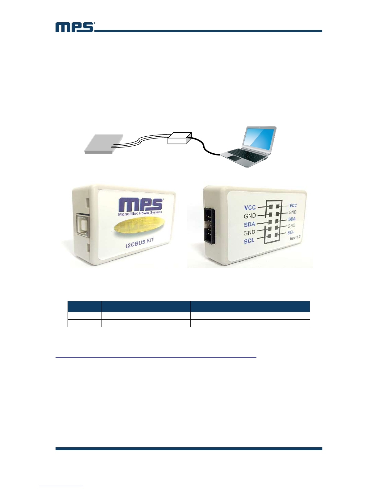
1. INTRODUCTION
PC I2CBUS KIT
EVB Board
DAT Wire
GND Wire
USB Cable
1.1 What Is the MPS I2C GUI?
The MPS I2C Interface system is a system that helps customers easily use MPS
parts with an I2C function. The system includes an EVB board, an I2CBUS KIT between
the PC and IC, and a computer with Windows 7 or higher system (see Figure 1 and
Figure 2).
Figure 1: MPS I2C Interface System
Figure 2: MPS I2CBUS KIT (Top and Bottom)
1.2 System Requirements
#
1 Operating System Windows 7 or later
2 .Net Framework .NET Framework 4.0 or later
NOTE: .Net Framework can be downloaded from Microsoft.com. The .net Framework4.0
can be downloaded here:
https://www.microsoft.com/en-US/download/details.aspx?id=17718
Software Version
2
Page 4
2. INSTALLATION
The MPS IIC GUI.rar can be downloaded from the MPS website. Extract it into a
directory.
2.1 Installing the MPS IIC GUI
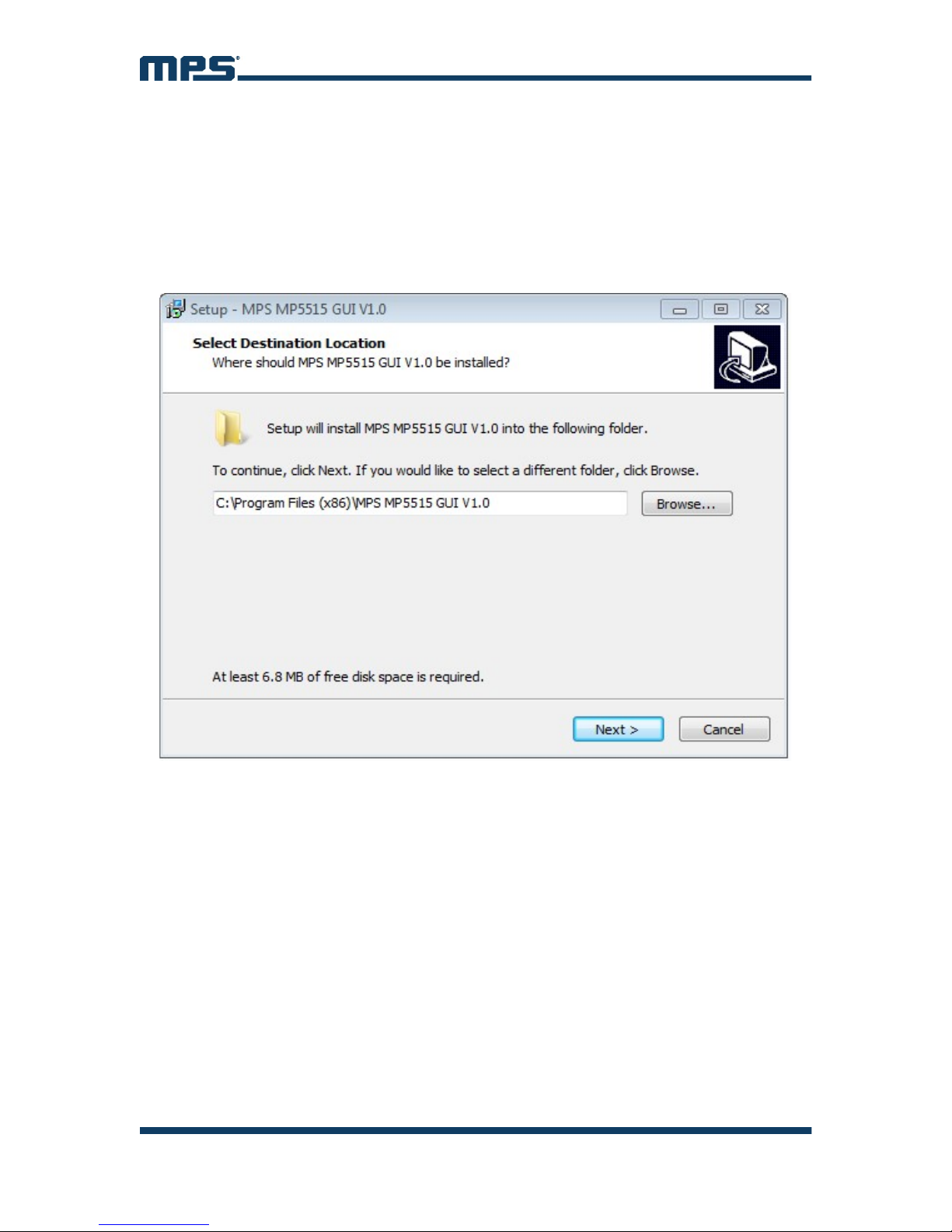
Double click the .exe file and flow the set-up guide (see Figure 3). For this example, we’ll
be using the MP5515.
Figure 3: MPS IIC GUI Set-Up Guide
2.2 Installing the USB Driver
The USB-to-I2C driver should be installed before using the system. Follow the steps
below to install this driver.
3
Page 5
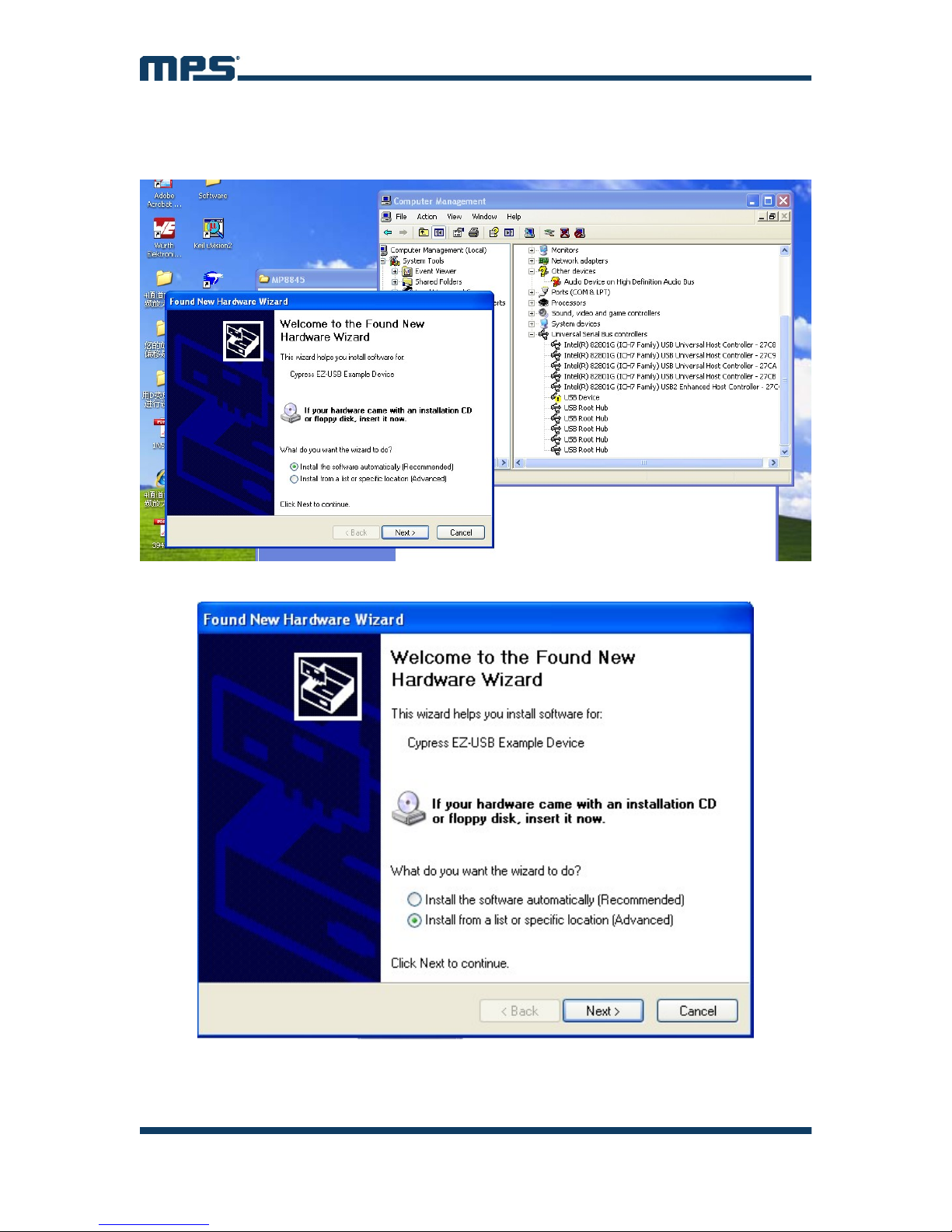
1. Connect the MPS I2CUSB KIT to your PC through the black USB cable.
Windows will find the new hardware and open a dialog box to instruct you on
installing the driver.
2. Select “Install from a list or specific location (Advanced)” and press “next”.
4
Page 6
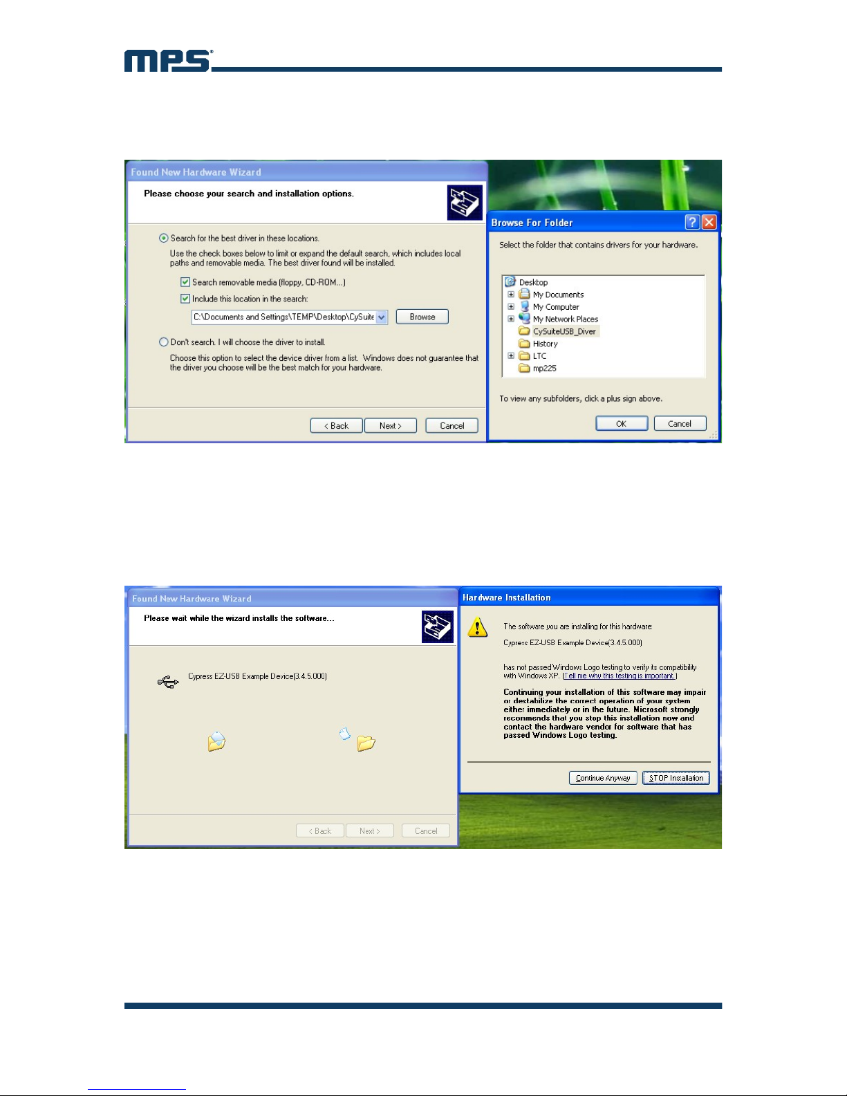
3. Browse to the location that you extracted the “.rar” file before and choose either the
“x86 Driver” or the “x64 Driver” folder, depending on your system type, and press
“next”.
Contact your system administrator is you need to know your PC’s system type.
4. Press “Continue Anyway” to install the driver. Wait for the installation to finish and
remove the USB cable from PC.
Sometimes the PC cannot recognize the USB device and shows an “unknown
USB device” warning. Try connecting the device to a different USB port. If that does
not work, please contact your administrator.
5
Page 7
3. USAGE
3.1 Hardware Connection
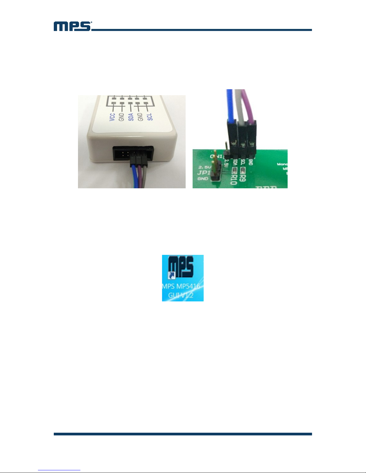
Use the colored wires to connect the EVB to the MPS I2CBUS KIT (see Figure 4).
Please refer to the specific part datasheet for EVB pin definitions.
Figure 4: EVB to MPS I2CBUS KIT Wire Connection
Refer to the EVB datasheet to start up the EVB and connect it to the PC via the IICBUS
KIT.
3.2 Using the GUI
After installing the software, start it up from by selecting the desktop shortcut icon or
from the Start menu.
Follow the steps below to use the GUI software.
6
Page 8

1. Start the software. It will check the EVB connection automatically. If the
connection is not successful, a warning will appear at the bottom. Otherwise, the
address will be listed in the “Slave Address.”
2. Select the part number, then, the control information will be seen in the “Register
Control.”
7
Page 9
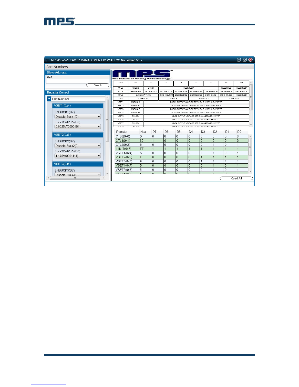
3. Find the item you want to change, select the value, and the changed information of
the item will appear on the right side. Click the “Read All” button to update all the
item’s values.
8
 Loading...