

MP Pumps, Inc. FRX100, FRX 125 Repair Manual
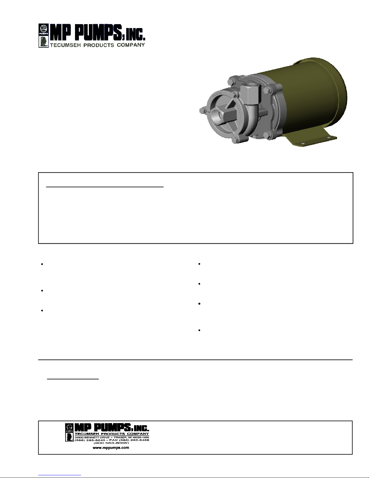
FRX100 316 STAINLESS STEEL CENTRIFUGAL PUMP
INSTALLATION, OPERATION, AND REPAIR MANUAL
GENERAL SAFETY INFORMATION
:
THE FOLLOWING WARNINGS ARE USED TO NOTIFY AND ADVISE THE USER OF THIS PRODUCT OF
PROCEDURES THAT MAY BE DANGEROUS TO THE USER OR RESULT IN DAMAGE TO THE PRODUCT.
THIS BULLETIN MUST BE READ COMPLETELY BEFORE INSTALLING, OPERATING, OR SERVICING,
THE PUMP.
DO NOT
perform service or maintenance
when the pumping system is pressurized.
Injury or death may occur.
DO NOT
operate the pump in a manner
that it was not intended to be used.
DO NOT
mount the pump such that high
piping loads exist on the pump flanges, or
in a rigid piping system that does not allow
the pipe to expand and cause the pump to
be strained.
INSTALLATION
:
Install the pump where the inlet is below the liquid level. A valve may be used to isolate the
pump for service. The pump is not self-priming and needs the inlet to be flooded at start-up.
The motor is splash resistant, not submersible, and should be located in a dry environment.
FRX 100 is a high performance 316 stainless steel
centrifugal pump. Its uses are marine, commercial,
and industrial transfer of chemicals or potable water.
All pump parts are 316 stainless for superior corrosion resistance when pumping chemical compounds. A carbon, ceramic, viton, bellows shaft seal is
standard. The FRX 100 is designed with 1 inch NPT
porting and the pump rotation can be achieved in 90 degree increments.
FORM 3808A (03-07)
DO NOT
continue to operate the pumping
system when a known leak exists.
DO NOT
continue to operate the pump
when unusual noise or vibration occurs.
DO NOT
operate beyond the pressure or
temperature limits stated in the product
literature. See Form 8110.
DO NOT
allow severe temperature changes
to occur in a short time period within the
pumping system.

PIPING/MOUNTING
:
The pump inlet and outlet has 1 pipe connections. Use
pipe sealant on the threads and other connections. The
base does not require direct mounting if one of the pipe
flanges is rigid mounted. Do not rigid mount both the
flanges and the base to avoid mounting tolerances that
may distort the motor base. Install the pump with the
shaft in a horizontal direction. Never install the pump
vertical with the motor below the pump.
ELECTRICAL
:
The motor must be protected from over current by using a
fuse or circuit breaker (see chart below for correct protection). The proper minimum wire size is stated for each
voltage application. Make sure that the pump has the
proper voltage rating to match the installation power. Do not
use or install if the voltage on the label is different that the
installation. All wire connections must be secure and sealed
to protect arcing. Follow all local installation codes.
OPERATION
:
The pump should be operated with liquid in the pump
otherwise seal damage may occur. If an inlet valve is
present, the valve should always be completely open
during operation to avoid cavitation. An outlet valve may
be used to throttle the flow rate. Avoid repeated starts
and stops; the pump can operate for a long period of
time without any flow.
REPAIR AND MAINTENANCE
:
The pump has a carbon/ceramic seal that may last several
thousand hours based upon the application. If the motor is
replaced, the mechanical shaft seal should also be replaced.
A seal that leaks will show leakage through the slot between the pump housing and the motor. Extreme leakage
may damage the motor bearings and contaminate the
inside of the motor.
DISASSEMBLY
:
1. Remove the three cover screws and remove the
cover discarding the o-ring.
2. Secure the motor shaft at the back of the motor and
remove the impeller by rotating it counter clockwise.
3. Remove the spring keeper, spring and rotating portion
of the seal by pulling them off by hand. A screw driver
may be used to pry the seal up if it is sticking.
4. Remove the four capscrews that hold the
housing /adaptor assembly onto the motor. Remove
the housing /adaptor assembly and push the seal
seat out from the back side using a screwdriver.
INSPECT PUMP PARTS
:
Always replace the mechanical seal. Check the seal for
dry run wear or damage. Check the motor shaft for wear
at the secondary sealing surface from the mechanical
seal. If worn, replace the motor. Check the motor bearings by rotating the motor by hand. If the shaft rotation is
not smooth or has radial / axial endplay, replace the
motor. Check the impeller running surface between the
impeller and cover. If the surfaces are worn or irregular,
replace each item.
Clean the parts that are to be reused using a solvent or
mild cleaner. Remove abrasive material.
REASSEMBLY
:
1. Press the new seal seat into the pump housing. A
light lubricant may be used to aid in the assembly.
Install the pump housing/adaptor assembly onto the
motor and fasten with the four capscrews.
2. Install the rotating portion of the mechanical seal
by sliding the seal (carbon side down) over the
motor shaft. Place the spring and spring keeper over
the back of the rotating portion of the seal.
3. Place the impeller onto the motor shaft, taking care to
pilot the spring keeper onto the shoulder at the back
of the impeller. Thread the impeller onto the motor
shaft until it bottoms out on the shaft. Thread locking
grade Loctite should be used to secure the nut.
4. Stretch the o-ring over the cover pilot. Install the cover
onto the housing and fasten the capscrews and
loc
ITEM PART NO. DESCRIPTION QTY.
NO.
1 34930 CAPSCREW - S.S. - 5/16-18 X 5/8 3
2 21238 LOCKWASHER - S.S. - 5/16 3
* 3 34926 COVER - 316 S.S. 1
* 4 35001 O-RING - VITON 1
* 5 34927 IMPELLER - 316 S.S. - 3.75 DIA. 1
* 6 35052 SEAL - VITON 1
* 7 34924 HOUSING - 316 S.S. 1
8 21251 HEXHEAD CAPSCREW - -S.S. - 3/8-16 X 7/8 4
9 21266 LOCKWASHER - S.S. -3/8 4
* 10 34928 ADAPTER RING - 56C 1
11 21435 SLINGER - NEO. - 1 X .6 1
12 33564 LOCKWASHER - S.S. - 1/4 4
13 21504 HEXHEAD CAPSCREW - S.S. - 1/4-20 X 5/8 4
14 35035 EL. MTR. - 56J TEFC 1
*- RECOMMENDED REPLACEMENT PARTS
kwashers.
FORM 3808A (03-07)
 Loading...