

Page 1
PETROLEUM SELF-PRIMING CENTRIFUGAL PUMPS
INSTRUCTION BULLETIN
Read this bulletin in full before installing, operating or servicing this pump. If any of the warnings of
this bulletin are ignored serious injury or death could occur.
WARNING!
This pump was designed to handle volatile and flammable fluids. To reduce the risk of fire or
explosion keep pump in well ventilated area free of explosive atmosphere. Do not smoke where
the fuel is being handled, also keep away from any sparks or open flame. Do not operate pump
with either the suction or discharge valves fully closed as this will over heat the pump. If pump
becomes overheated allow to cool before next use.
Do not operate the pump in a manner that
it was not intended to be used.
Do not install a piping system that does Do not continue to operate the pumping
not allow for any flex due to expansion from system when unusual noise or vibration
heat generated by the pumping system.
Do not allow severe temperature changes Do not perform service or maintenance
to occur in a short time period within the when the pumping system is pressurized
pumping system.
Drain pump completely before switching Do not mount pump in conditions that high
fuel type that is to be pumped. piping loads exist on the pump flanges.
Do not continue to operate the pumping
system when a known leak exists or the
system starts to smoke.
occurs.
or hot.
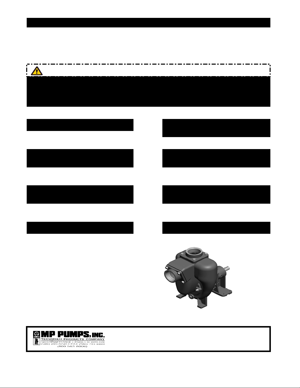
MODELS:
PO Biodiesel, Diesel and Fuel Oil.
PG Gasoline, Kerosene, Avgas
Jet A and JP 8 Fuel.
PE Ethanol and E-85.
FORM 3074-A (2/08)
PRINTED IN THE U.S.A.
Page 2

PETROLEUM SELF-PRIMING CENTRIFUGAL PUMPS
INSTRUCTION BULLETIN
It is important that this Instruction Bulletin be read carefully to fully familiarize yourself with the pump
assembly arrangement. The instructions contained herein pertain to installation and maintenance of the
pump assembly only. Check unit carefully to make certain that no parts are missing or have been broken
in shipment.
INSTALLATION
For optimum performance, place pump as close
to liquid source as possible to reduce suction lift
to a minimum. For best results, pump should be
installed not more than 15 feet above the liquid
supply. Set the unit on solid footing and as
nearly level as possible.
Pipe or hose of the same size as the provided
flanges should be used. Reinforced suction hose
is recommended providing greater flexibility and
prevents collapsing due to vacuum in the suction
line when pump is in operation. The suction line
should be as short as possible to keep friction
loss at a minimum. Use pipe sealant on all the
connections and make certain that all fittings are If the pump is to be left standing idle for any
tight, particularly on the suction line where an air length of time in freezing conditions, the pump
leak can prevent priming or reduce pump capacity.
OPERATION
pump and only requires priming prior to its initial
start. The pump will retain sufficient liquid for
self-priming thereafter.
The impeller on the PO,PG,PE 5 and 8 is
threaded to a stainless steel drive sleeve.
The impeller on the PO,PG,PE 10 and 15 has
stainless cover pressed on. The sleeve slips
over the drive shaft and is locked to the drive
shaft with a two piece clamp. This means that
a standard drive shaft is used - no special taper
or threads. It is easy to adjust or remove the
impeller.
This pump is equipped with a self-lubricated
shaft seal. The self-lubricated seal is lubricated
by the liquid in the pump. Operating the pump
dry will seriously damage the mechanical seal.
housing should be drained. A drain plug at the
base of the pump housing is provided for
draining.
DISASSEMBLYThis petroleum pump is a self-priming centrifugal
Disconnect power to prevent accidentally
starting.
If pump fails to prime or stops pumping, check for Disconnect lines and drain pump housing.
the following possible causes:
TO REMOVE PUMP HOUSING
1. No liquid in the pump housing
2. Air leak in the suction line due to loose
connections or pin holes in the hose.
3. Collapsed suction line or clogged strainer
4. Seal worn and leaked air.
5. Worn impeller - too much clearance
between impeller and wear plate.
6. Pump not running fast enough.
7. Suction lift is too high.
8. Trying to prime against too high a
MAINTENANCE
This pump is of simple construction with only
one moving part.
Remove cap screws and nuts holding pump
housing to base (where used).
Remove nuts and lock washers holding the
pump housing to adapter.
Loosen the housing and remove carefully to
prevent tearing gaskets.
TO REMOVE IMPELLER discharge head.
Remove impeller clamp nuts and clamp to
unlock impeller drive sleeve from drive shaft.
Page 3

Use two pry bars or large screwdrivers
diagonally across from each other between
adapter and end of drive sleeve. Pry the sleeve
off the drive shaft.
Before removing the seal from the impeller,
inspect the carbon washer. If nicked or worn,
replace it with a new one. Inspect seal seat (still
in the pump adapter). If no nicks, scratches or
cracks appear and the surface is clean and
smooth, there is no need to replace it. If replacement is necessary, remove adapter by removing
four hex nuts and washers. Place adapter on flat
surface, with impeller side down. Press out seal
seat by using wooden end of a screw driver or
similar tool. ( SEE PARAGRAPH REFERRING
TO REASSEMBLY ).
TO REPLACE IMPELLER
On the threaded sleeve of this pump it is not
necessary to remove the seal. Clamp the drive
sleeve using caution not to mar the seal surface.
Hold firmly and unthread impeller by turning
counterclockwise - left hand. Replace with a
new impeller. Be sure seal spring fits over hub
on back of impeller.
TO REMOVE ADAPTER
Remove the four nuts and lock washers.
Loosen and remove adapter.
TO INSPECT SELF-LUBRICATED
SEAL ASSEMBLY (See Fig. 1)
FIGURE 1
TO REMOVE WEAR PLATE
After pump housing has been removed from
the adapter, inspect the wear plate. If wear
plate is badly worn, it should be replaced. To
remove wear plate, loosen and remove acorn
nuts and gaskets on the outside of the pump
housing.
CAUTION
When replacing wear plate, be sure to use
new gaskets under acorn nuts to seal
against air leaking in on suction side
during priming cycle.
INSPECTION
After pump has been disassembled, check all
parts over carefully for wear or damage. When
ordering parts for your pump, be sure to specify
the model and serial numbers shown on the
name plate.
After the impeller and drive sleeve have
been removed from the drive shaft, inspect
the lapped sealing face of carbon washer
(Part 3) for wear which would necessitate
replacement.
Inspect lapped sealing face of floating seat
(Part 4) in adapter housing counterbore for
scuffing or cracks. If necessary to replace,
press out old seat and ring, and proceed as
outlined in paragraph on MOUNTING
ADAPTER.
If spring &/or bellows (Part 1 & 2) are damaged
and require replacement, lubricate the impeller
sleeve with a suitable lubricant for the fluid
being pumped and slide parts off sleeve.
REASSEMBLY
MOUNTING ADAPTER
Before mounting adapter, thoroughly clean the
counterbore.
Clean and lubricate the synthetic member on
seal seat and press (do not drive) the assembly
into the adapter counterbore, seating it firmly
and squarely.
CAUTION
In handling, avoid dropping seat and take
particular care not to scratch the lapped
face.
Page 4

Install adapter. Install lock washers and tighten
four nuts evenly.
MOUNTING SELF-LUBRICATED
SEAL ASSEMBLY (See Fig.1)
Mount seat and seat ring (Part 4 and 5) as
outlined above. Inspect impeller sleeve for
nicks and burrs. Polish sleeve with fine emery
or crocus cloth. Then clean and lubricate with
a clean light oil.
Slip the spring (Part 1) onto the impeller
sleeve making certain that it is seated properly
on the shoulder of the impeller.
assembly (Part 2 and 3) with a clean light oil
and slide it onto the impeller drive sleeve only
until it clears the chamfer.
IMPORTANT
The assembly of impeller and seal to the drive
shaft should take place as soon as the bellows
assembly is slipped on the impeller sleeve so
as to avoid bonding of the bellows to the sleeve
at the improper working height.
CAUTION
Foreign matter between sealing faces will
cause leakage and shorten life of the seal.
MOUNTING PUMP HOUSING
Replace gaskets on pump housing and mountLubricate the inside of the washer and bellows
the housing on the adapter. Replace two lock
washers and nuts on studs diagonally across
from each other and tighten.
Slide the seal bellows and washer assembly
onto the impeller drive sleeve. Push the seal
down over the drive sleeve with even pressure.
Pull the seal head back up to the position
where there is no spring load. This insures
proper assembly on the drive sleeve.
Before sliding the impeller onto the drive
shaft, wipe the lapped sealing faces of the
floating seat (Part 4) in the adapter counter
bore and the carbon washer (Part 3) on the
bellows assembly perfectly clean.
Then lubricate both faces with a clean light
oil.
Turn drive shaft over slowly by hand and listen
at outlet opening on housing for any rubbing of
the impeller on the housing or wear plate.
The clearance between the impeller and wear
plate can be checked with a feeler gauge.
Normal clearance is .015" to .025". If the
clearance exceeds .025" readjust impeller. If
the impeller rubs use an additional gasket to
space impeller.
After clearance has been established, replace
lock washers and nuts on remaining studs and
tighten. If cap screw and nuts are used to hold
housing to mounting base, replace these and
tighten.
FORM 3074-A (2/08)
PRINTED IN THE U.S.A.
 Loading...