

Page 1
HYDRASUB 20/25 HYDRAULICALL Y DRIVEN SUBMERSIBLE PUMP
INSTALLATION, OPERATION, AND REPAIR MANUAL
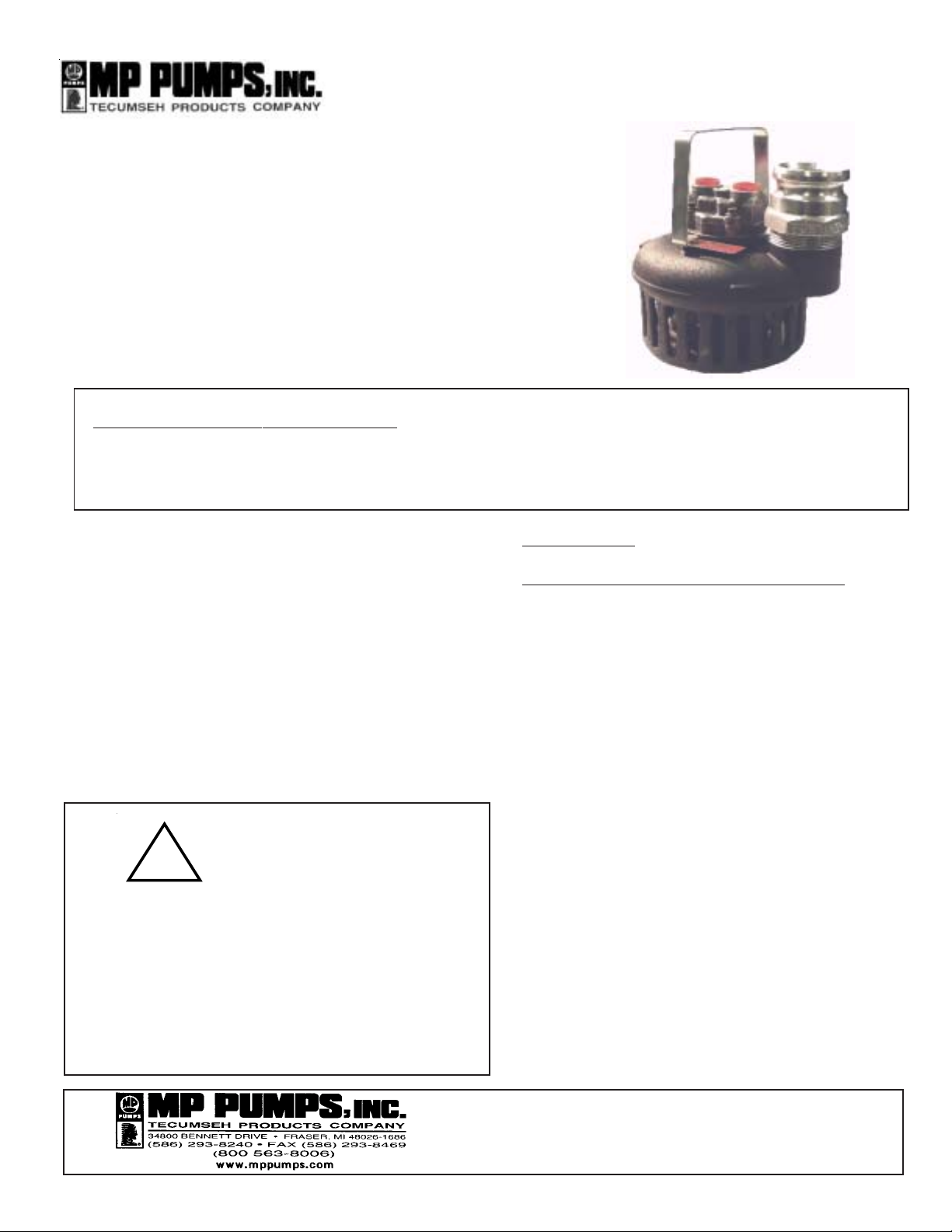
HYDRASUB 20/25 is a compact, lightweight,
hydraulically driven submersible pump with high flow
capabilities. This self-priming pump is made with a
high strength aluminum alloy that is anodized for
corrosion resistance. This pump features a stainless
steel impeller, ball bearing, and a gerotor type
hydraulic motor. HYDRASUB 20/25 may be used to
pump out underground vaults and pits.
GENERAL SAFETY INFORMATION:
THE FOLLOWING WARNINGS ARE USED T O NOTIFY AND ADVISE THE USER OF THIS PRODUCT OF PROCEDURES
THAT MAY BE DANGEROUS T O THE USER OR RESULT IN DAMAGE TO THE PRODUCT.
THIS BULLETIN MUST BE READ COMPLETEL Y BEFORE INST ALLING, OPERATING, OR SERVICING, THE PUMP.
• DO NOT perform service or maintenance
when the pumping system is pressurized.
• DO NOT continue to operate the pumping
system when a known leak exists.
• DO NOT operate beyond the pressure
or temperature limits stated in the product
literature. See Form 8107/8108.
• DO NOT operate the pump in a manner
that it was not intended to be used.
• DO NOT use in explosive atmospheres or
pump volatile liquids.
WARNING
NEVER OPERA TE THE PUMP WITH UNSECURED HOSES
AND HYDRAULIC LINES. SEVERE INJURY MAY OCCUR
FROM IMPACT, IMPINGEMENT, OR LIQUID BLAST.
COLD WEATHER OPERATION MAY REQUIRE
PREHEATING THE OIL OR BYPASSING THE OIL IN THE
POWER SUPPLY TO PREHEAT IT UNTIL THE OIL
REACHES A TEMPERATURE OF 50oF.
!
INSTALLATION:
HYDRAULIC OIL SYSTEM REQUIREMENTS:
The hydraulic power supply must be capable of delivering a
controlled flow rate of 5-9gpm for Model 20 and 8-14gpm for
Model 25. The operating oil pressure will vary upon the flow
rate load of the pump from 700 to 2100 psi. A maximum relief
valve setting of 2400psi is recommended.
A hydraulic supply system where the flow rate is controlled is
referred to as an “open center system.” This is the most
accurate system to assure that the flow rate does not exceed
the maximum limit.
A “closed center system” will have a variable oil flow rate based
upon the hydraulic pressure that is a set value. If a closed
center system is used, the maximum pressure developed must
not exceed 1700 psi, and the pump must always have a
supply of water to pump to protect it from running into an over
speed condition unless the oil flow rate is limited to less than
the maximum.
The maximum return pressure or backpressure is 100psi.
Higher pressures will result in reduced seal life. Do not install
down stream loads or valves. Always allow the return to go
directly back to the tank.
Supplemental oil cooling may be required to keep the oil
temperature below 175
(25 micron recommendation) to clean the oil of contaminants
that may accelerate wear.
0
F. Suitable filtration is required
FORM 3069A (05-04)
Page 2

CONNECTING TO THE POWER SOURCE:
The pressure and return ports are noted on the pump casting
closest to the hydraulic motor connection. Connecting the ports
in opposite orientation will result in damage to the hydraulic motor
components and lip seal. The Model 20 uses SAE #8 hydraulic
o-ring connections with a minimum hose size of .50 inches. The
Model 25 uses SAE #10 hydraulic o-ring connections with a
minimum hose size of .625 inches. Hose should be rated for
operating at 2500psi or greater.
CONNECTING TO THE PUMP DISCHARGE:
Model 20 has a 2” cam and groove connection, and Model 25 has
a 2.5” cam and groove. Attach a suit able length of hose and lock
the connector using a safety lock or wire. Do not install a discharge
valve or nozzle. The outlet must not be restricted or reduced.
LOWERING THE PUMP INTO THE HOLE:
The pump can be lowered into the hole after all connections are
made to the pump. A rope or cable can be attached to the handle
or the pump can be lowered by the hose and hydraulic lines to rest
onto a solid floor or base. If the pump is to be suspended,
support cables must be used to secure the pump from rotating and
support the weight of the discharge hose when it is full of water.
Never suspend a pump by using the hoses to hold the pump. For
best optimum pumping performance, keep the pump in an upright
position. The discharge hose must be secured at the end and at
the point where the hose exits the hole. Avoid kinks and sharp
bends to the hydraulic lines.
OPERATION:
Energize the hydraulic power source. Check and adjust the oil
flow rate if necessary. Check the discharge hose for kinks and
make sure that they are securely restrained. If adjustments to the
hoses are required, shut down the power, adjust, and then
restart. Adjusting the discharge hose during operation may
result in injury to the operator. When pumping solids, set the
pump for maximum flow to keep the solids suspended and expelled
through the discharge hose. Accumulating solids within the
discharge will reduce the flow and may cause accelerated wear to
the pump if solids backup into the pump housing. It may also
require periodic maintenance to clear the discharge hose. The
pump will clear all liquid to within .75 inches of the pump base.
Periodically clear debris that may accumulate around the pump
inlets. The pump is capable of pumping any solid material that will
fit through the strainer opening. Maintaining a low level can be
accomplished with the pump operating in air. When evacuating to
depths over 30 feet, a check valve at the pump discharge may be
used to keep the water from flowing backwards when the pump
has cleared to a low level and is pumping in air. When pumping
is completed, shut off the hydraulic supply before removing the
pump from the hole. The pump may remain in the hole after use
for long periods of time if intermittent use is required.
REPAIR:
Normal rebuild service may be required to replace the lip seals
after 3,000-6,000 hours of operation. The pump will require
complete disassembly. Any wear to the hydraulic motor parts
will require complete replacement of the hydraulic motor
assembly . Visible wear to the pump parts is not as critical as the
motor components.
HYDRASUB pumps do not require any adjustments or special
clearance settings when assembling or rebuilding.
DISASSEMBLY:
(See exploded view and parts description)
1. Remove the five cover plate screws and remove the cover.
2. Remove the three screws that hold the suction flange, and
remove the suction flange.
3. Remove the two handle screws and remove the handle.
4. Remove the four hydraulic motor screws and remove the
hydraulic motor cover, gerotor element with drive pin, and the
thrust plate.
5. Secure the impeller and unthread the impeller from the shaft
using a wrench on the flats at the ball bearing. The thread is
a left hand thread that requires opposite rotation for removal.
6. Remove the shaft and bearing assembly by first removing the
retaining ring, then apply pressure to slide the shaft and
bearing out of the motor side of the pump housing.
7. Remove the two lip seals by pushing the seals out through the
motor side of the pump body .
INSPECT THE PUMP PARTS:
Clean all foreign material off the parts. DO NOT use abrasive
cleaning methods on the hydraulic parts or shaft.
Check the motor shaft for wear at the lip seal surface. If it has
grooves greater than .003 inches deep, the shaft should be
replaced.
Check the hydraulic motor parts for wear. Any appearance of
displaced metal or surface smearing will require replacing all of
the motor parts.
Check the impeller blade surface between the impeller and the
suction flange. If the surfaces are severely worn, or the impeller
blades are bent, replace each item.
Clean the parts that are to be reused using a solvent or mild
cleaner. Remove abrasive material. Cleanliness of the hydraulic
motor parts is very important.
2
Page 3

REASSEMBLY:
1. Press the new lip seals into the pump housing using a suitable
bushing or socket. A light lubricant may be used to aid the
assembly . The proper assembly is to install the seals back to
back, installing one seal at a time.
6. Place the drive pin onto the shaft slot and hold it in
position with a screwdriver while sliding the gerotor
over the shaft and stopping at the thrust plate. Line
up the gerotor and thrust plate.
2. Press the new ball bearing onto the shaft by pressing against
the inner face of the bearing until it is seated against the
shaft shoulder . The first lip seal should be installed open face
down and flat side facing out. The second lip seal should be
installed flat side in.
3. Lubricate the impeller side of the shaft with oil. Push the shaft/
bearing into the body using care to align the shaft at the
center of the lip seal until it is at the bottom of the shoulder in
the body. Inst all the snap ring to secure the shaft assembly .
4. Secure the shaft with a wrench on the flats of the shaft and
thread the impeller onto the shaft (note left hand thread).
Tighten the impeller until it shoulders onto the shaf t.
5. Place new quad rings onto the thrust plate. Use a small amount
of grease to hold the quad rings from moving out of position.
Place the thrust plate over the shaft with the kidney slot up
away from the bearing. Kidney should be on the pressure
side of the motor.
7. Install the cover onto the shaft; some sideways movement
of the gerotor is necessary . The dowel pins should go
through the thrust plate and into the body . Do not force this
assembly by using a hammer or press, it will slide together
when it is in position.
8. Install the four motor cover screws and torque to 17-ft.lbs
in a cross pattern with the first torque @ 10-ft.lbs.
9. Install the suction flange and screws.
10. Install the handle and screws.
11. Check for free rot ation by rotating the impeller by hand. If it
does not rotate, remove the motor cover, clean the motor
parts, and reassemble. Dust and dirt granules will impede
motor rotation.
12. Install the cover plate using five screws and lockwashers.
3
Page 4

TROUBLESHOOTING
If problems develop, use the chart below to service the pump.
Pump will not start
Poor pump performance
No hydraulic flow and pressure
Hydraulic motor
Couplers
Hydraulic connection
Hydraulic oil flow is low
Pump is too deep in sediment
Turn power on. Check to make sure
the oil flow range (5-9gpm /
8-14gpm), and 2000psi oil pressure are
ok.
Repair or replace as needed.
Check to make sure the couplers are
completely connected and not defective.
If defective, replace.
Connected backwards. Reinstall in
proper direction.
Turn power on. Check to make sure
the oil flow range (5-9gpm /
8-14gpm), and 2000psi oil pressure are
ok.
Place pump on solid support.
Pump intake is plugged
Discharge hose is twisted or kinked
Discharge hose is too small
Lift is too high for power supply
Pump not sufficient for application
Damaged or worn impeller
FORM 3069A (05-04)
Make sure debris has not wrapped
around base of pump.
Make sure the hose is straight.
Make sure hoses are 2” dia. Model 20,
and 2-1.2” dia. Model 25.
Maximum lift is 70ft Model20, and 95 ft.
Model 25.
Make sure pump specs are sufficient for
application.
Replace as required.
4
 Loading...