

MP Pumps FRX-75 SP User Manual
®
®
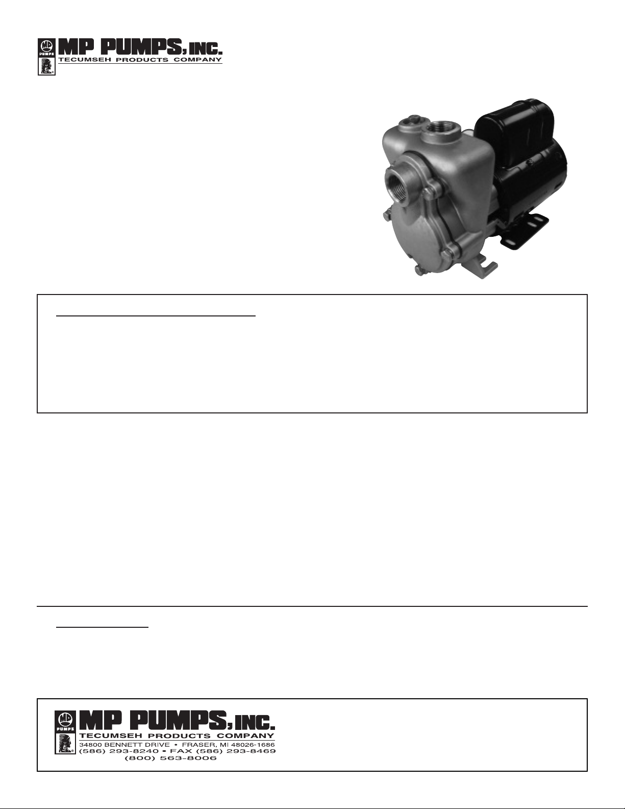
FRX 75-SP STAINLESS STEEL CENTRIFUGAL PUMP
INSTALLATION, OPERATION, AND REPAIR MANUAL
Model FRX 75-SP is a high performance
selfpriming 316 stainless steel centrifugal pump.
The pump is ideal for marine, industrial,
agricultural or commercial applications where
suction lift is required.
The FRX 75-SP model features all 316 stainless
steel components for superior corrosion
resistance when pumping chemical compounds.
A carbon / ceramic / viton bellows seal is
standard. Ports are 3/4" with 1/8" NPT fill port.
The FRX 75-SP model is capable of 12 foot suction lift (3450 rpm).
Patent Pending
GENERAL SAFETY INFORMATION:
THE FOLLOWING WARNINGS ARE USED TO NOTIFY AND ADVISE THE USER OF THIS PRODUCT OF
PROCEDURES THAT MAY BE DANGEROUS TO THE USER OR RESULT IN DAMAGE TO THE PRODUCT.
THIS BULLETIN MUST BE READ COMPLETELY BEFORE INSTALLING, OPERATING, OR SERVICING,
THE PUMP.
• DO NOT perform service or maintenance
when the pumping system is pressurized.
Injury or death may occur.
• DO NOT operate the pump in a manner
that it was not intended to be used.
• DO NOT mount the pump such that high
piping loads exist on the pump flanges, or
in a rigid piping system that does not allow
the pipe to expand and cause the pump to
be strained.
• DO NOT continue to operate the pumping
system when a known leak exists.
• DO NOT continue to operate the pump
when unusual noise or vibration occurs.
• DO NOT operate beyond the pressure or
temperature limits stated in the product
literature. See Form 8110.
• DO NOT allow severe temperature changes
to occur in a short time period within the
pumping system.
INSTALLATION:
For optimum performance, place the pump as close to the liquid as possible to minimize suction
lift. For best results, the pump should be installed no more than 10 feet above the liquid supply.
The motor is splash resistant, not submersible, and should be located in a dry environment.
FORM 3807A (08-06)

®
PIPING/MOUNTING:
The pump inlet and outlet has 3/4" pipe connections. Use
p
ipe sealant on the threads and other connections. The
base does not require direct mounting if one of the pipe
flanges is rigid mounted. Do not rigid mount both the flanges
and the base to avoid mounting tolerances that may distort
the motor base. Install the pump with the shaft in a
horizontal direction. Never install the pump vertical with the
motor below the pump.
ELECTRICAL
:
The motor must be protected from over current by using a
fuse or circuit breaker (see chart below for correct protection).
The proper minimum wire size is stated for each
voltage application. Make sure that the pump has the
proper voltage rating to match the installation power. Do not
use or install if the voltage on the label is different than the
installation. All wire connections must be secure and sealed
to protect against arcing.
Follow all local installation codes.
MOTOR VOLTAGE FUSE/CB WIRE SIZE
ON NAME PLATE AMPS AWG
12VDC 15 14
24VDC 10 16
32VDC 6 18
115VAC 2 18
230VAC 118
OPERA
TION:
The FRX 75 SP is a self-priming centrifugal pump
and only requires priming prior to its initial start-up.
This is accomplished by removing the priming plug and
filling the chamber with liquid.
The pump will retain sufficient liquid for self-priming
thereafter.
REP
AIR AND MAINTENANCE:
DC motor brush life expectancy is 6,000 hours total brush
life. The motor is not rebuildable after the brushes have
worn to the limits.
The pump has a carbon/ceramic seal that may last several
thousand hours based upon the application. If the motor is
replaced, the mechanical shaft seal should also be replaced.
A seal that leaks will show leakage through the slot between
the pump housing and the motor. Extreme leakage may
damage the motor bearings and contaminate the
inside of the motor.
11
10
9
8
7
6
5
4
3
2
1
12
DISASSEMBL
Y:
1. Remove five cover screws and remove the
cover and gasket.
2. Remove snap ring and wear plate.
3. Secure the impeller and remove the impeller
lock nut. Pull the impeller straight out off the
motor shaft.
4. Remove the seal-rotating portion by pulling
the seal off by hand.
5. Remove the capscrews that hold the pump housing
onto the motor. Remove the pump housing and push the
seal seat out using a screwdriver.
INSPECT PUMP P
ARTS:
Always replace the mechanical seal. Check the seal for
dry run wear or damage. Check the motor shaft for wear
at the secondary sealing surface from the mechanical
seal. If worn, replace the motor. Check the motor bearings
by rotating the motor by hand. If the shaft rotation is
not smooth or has radial/axial endplay, replace the
motor. Check the impeller running surface between the
impeller and cover. If the surfaces are worn or irregular,
replace each item.
Clean the parts that are to be reused using a solvent or
mild cleaner. Remove abrasive material.
REASSEMBL
Y:
1. Press the new seal seat into the pump housing.
A light lubricant may be used to aid the assembly.
Install the pump housing onto the motor and fasten
the screws through the motor.
2. Install the rotating portion of the mechanical seal
by sliding the seal over the motor shaft.
Do not use any lubricant.
3. Place the impeller onto the shaft over the "D" drive
against the shoulder and tighten the impeller lock nut
until the impeller is securely shouldered on the motor
shaft. Thread locking grade Loctite should be used
to secure the nut.
4. Replace wear plate and snap ring. Check the pump
for internal interference by rotating the impeller.
The pump should rotate freely with only seal friction.
5. Install the gasket and cover onto housing
and fasten with capscrews and lockwashers.
ITEM
QTY. PART NO. DESCRIPTION
1 5 35039 CAPSCREW - 316 S.S. - 1/4-20 X 5/8
2 5 33564 LOCKWASHER - 316 SS - 1/4
3 1 35024 COVER - 316 SS MACH.
4 1 35025 GASKET - VITON 70 DUROMETER
5 1 35027 RETAINING RING - 316 SS
6 1 35026 WEAR PLATE - 316 SS
7 1 28766 ACORN NUT - 316 SS
8 1 34033 IMPELLER - 316 SS
9 1 34038 MECHANICAL SEAL - VITON
10 1 25022 HOUSING - 316 SS MACH.
11 1 21255 PIPE PLUG - 18" NPT 316 SS
12 1 34036 EL. MOTOR - 12VDC
34293 EL. MOTOR - 24VDC
34504 EL. MOTOR - 115VAC ODP
35178 EL.MOTOR - 115VAC TENV
35179 EL. MOTOR - 230VAC TENV
FORM 3807A (08-06)
 Loading...