

MPPT SMPPT10D, SMPPT20D, SMPPT30D Operation Manual
SMPPT
Solar Charge Controller with
Maximum Power Point Tracking
10A/20A/30A 12V/24V
Installation & Operation Manual

SMPPT Installation & Operation Manual Version 1.0
1

SMPPT Installation & Operation Manual Version 1.0
2
Dear Consumer:
Thank you very much for using our product! We will offer you the
permanent and reliable service for your solar system!
The manual gives important recommendations for installing and
using the MPPT controller. Please read the manual carefully and
thoroughly before using this product.

SMPPT Installation & Operation Manual Version 1.0
3
1. Safety Instructions
(1) The controller is only designed to be connected to the off-grid solar
system. It offers the management of charging and discharging for the
lead-acid battery of flooded, gel and AGM chemistries from 12V to 24V
nominal only. Do not connect this controller to other system, such as
mains supply and windmill generator.
(2) The controller is intended for indoor use only. Protect it from direct
sunlight and place it in a dry environment.
(3) Batteries generate explosive gases during normal operation. It is
important never allow a spark or flame in vicinity of battery.
(4) Be sure to always keep children away from batteries and acid!
(5) Do not disassemble the MPPT controller, it does not have any
user-serviceable parts.
(6) The controller warms up during normal operation. Do not touch the
heatsink at the bottom of the controller.
Note:
It is important that the battery is fully charged frequently (at least
monthly). Otherwise the battery will be permanently damaged.
2. MPPT Controller Instructions
2.1 Overview
SMPPT solar charge controller is multi-stage Maximum Power Point
Tracking (MPPT) photovoltaic battery charge controller with our own
technology. It’s main topology adopts in Buck conversion circuit, and uses
MCU to adjust the solar panels working point intelligently in order to make the
solar panels output its maximum power. When the circumstances change, the
working point of solar panels deviate from the maximum power point, MCU will
adjust the solar panels working point based on MPPT calculation to make the
solar panels back to the maximum power point again(refer to Chapter 2.4
about MPPT technology introduction). Compared with PWM controller, MPPT
controller can increase the output power of solar panels by 5%~30%. The
output power increasing proportion is affected by the factors such as solar
panels property, humidity and light intensity. The controller uses wall-mount
installing (refer to Chapter 4.1). Connecting terminal makes the wiring area
bigger and wiring loss less.

SMPPT Installation & Operation Manual Version 1.0
4
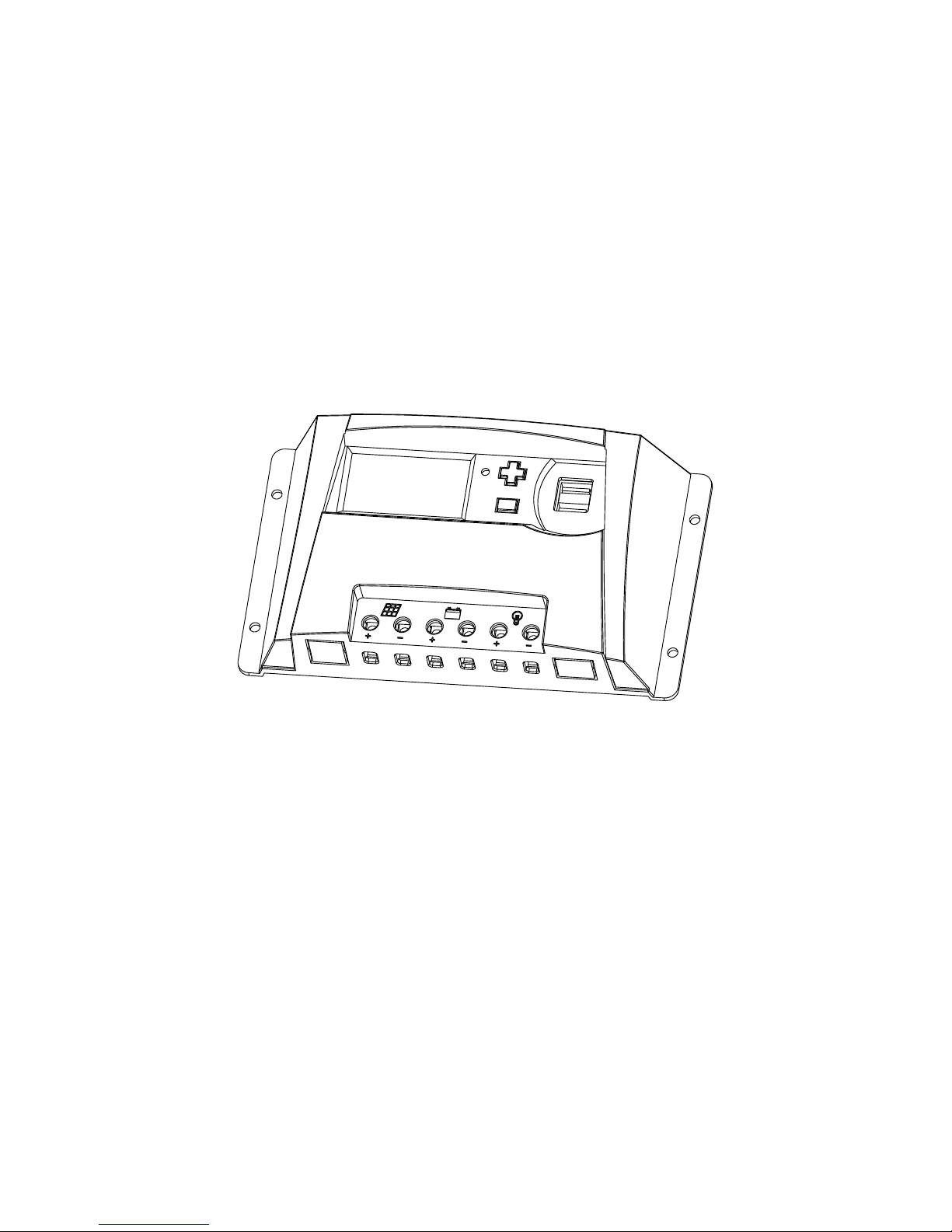
2.2 Structure
Figure 2-1: Controller Structure Diagram
2.3 Functions
(1) Maximum Power Point Tracking technology
The controller uses Buck conversion circuit and MCU technology to track
the maximum power point to implement the maximum output power of solar
panels in different illumination intensity and temperature. The MPPT
algorithm increases efficiency of your PV system and decreases the
quantity of solar panels.
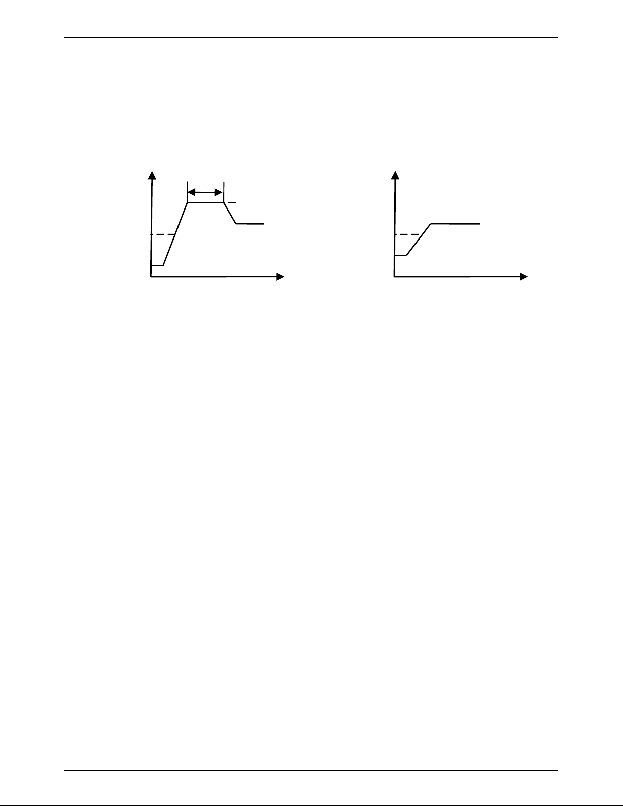
(2) Multi-stage Charge Control
The starting charging voltage of battery is different, the controller will use
the different charging strategies to finalize the charging process. When
starting charging voltage of battery is lower than 12.6V (for 12V battery),
battery will go through three stages as Bulk, Absorption and Float charging.
When starting charging voltage of battery is higher than 12.6V (for 12V
battery), battery will go through two stages as Bulk and Float charging.
Bulk Charge:
The controller charges the battery by its maximum output current. It is at
maximum power point tracking state at this phrase.
Absorption Charge:
The controller begins to limit the charging current to make the battery
voltage fixed at a settled absorption voltage (this voltage has temperature
compensation) for 2 hours. It increases the charging saturation level of
⑤
① LCD Display Screen
② Temperature Sensor
③ Button
④ USB Output
⑤ Solar Terminal Block
⑥ Battery Terminal Block
⑦ Load Terminal Block
⑥ ⑦
① ② ③
④
SMPPT Installation & Operation Manual Version 1.0
5
battery and prevents battery from leaking gas, and this can increase the
lifetime of battery.
Float Charge:
The battery is at saturation state, and the controller charges the battery at a
trickle current to make the battery voltage fixed at the settled float charging
voltage (this voltage has temperature compensation).
(3) Charge Voltage Temperature-compensated
The controller will compensate the Float charging voltage and Absorption
charging voltage by -4mV/Cell/°C based on the current battery
temperature.
For 12V battery, the compensated voltage U=(t-25)*6*(-0.004)V
For 24V battery, the compensated voltage U=(t-25)*12*(-0.004)V
(4) Discharge Control
The controller monitors the battery voltage all the time. The load will be
switched off when the voltage less than the Low Voltage Disconnect (LVD)
point, and it won’t be switched on until the voltage more than the Low
Voltage Reconnect (LVR) point.
(5) Protection against Reverse Connected Battery
Connecting the battery to the controller by reversed polarity (under the
circumstances of solar panels disconnected) will not damage the controller.
The controller will work normally after connecting with correct polarity.
(6) Protection against Reverse Connected Solar Modules
Connecting the solar modules with the controller by reserved connection
will not damage the controller. The controller will work normally after
connecting with correct polarity.
(7) Reverse Current Protection
The controller prevents reverse current from flowing into the solar modules
12.2V
Absorption
Float
Figure 2-2: Three-stage Charge
t
2h
U
Bulk
12.7V
Float
Figure 2-3: Two-stage Charge
t
U
Bulk
SMPPT Installation & Operation Manual Version 1.0
6
at night. An additional reverse current diode is not required.
(8) Overtemperature Protection
If the temperature inside the controller becomes too high, then the
controller will stop charging to the battery, and it will restart charging the
battery again when the temperature decreases to a certain value.
(9) PV Overvoltage Protection
If the input voltage of solar panels exceeds the maximum voltage permitted
by the controller, it will enter into protection state automatically and stop
charging. When the input voltage recovers to the normal range, the
controller will start charging again.
(10) Current-limited for Excessive Charging Current
If the permissible charge current is exceed, the controller will deviate from
the maximum power point to limit the output current to prevent the
controller being damaged.
(11) Load Output Overload Protection
If the permissible load current is exceed, then the load output is switched
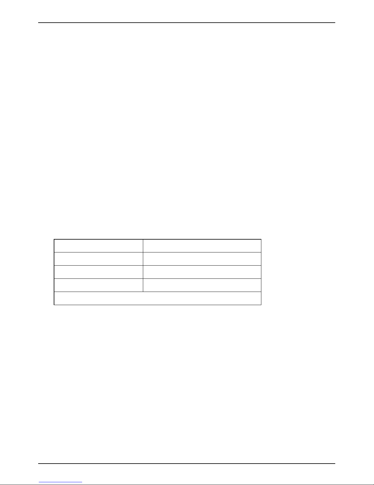
off. The overload current vs. duration shows as follows:
Rate of Current Duration (s)
1.2Irate ≤I< 1.5Irate
60
1.5Irate ≤I< 1.8Irate
10
I≥ 1.8Irate 0.2
Note:
Irate=10A/20A/30A, nominal load current
The controller restarts the load every 6 minutes automatically, but the user
can also restart the load by the Load key(Load key chapter 5.2.2).
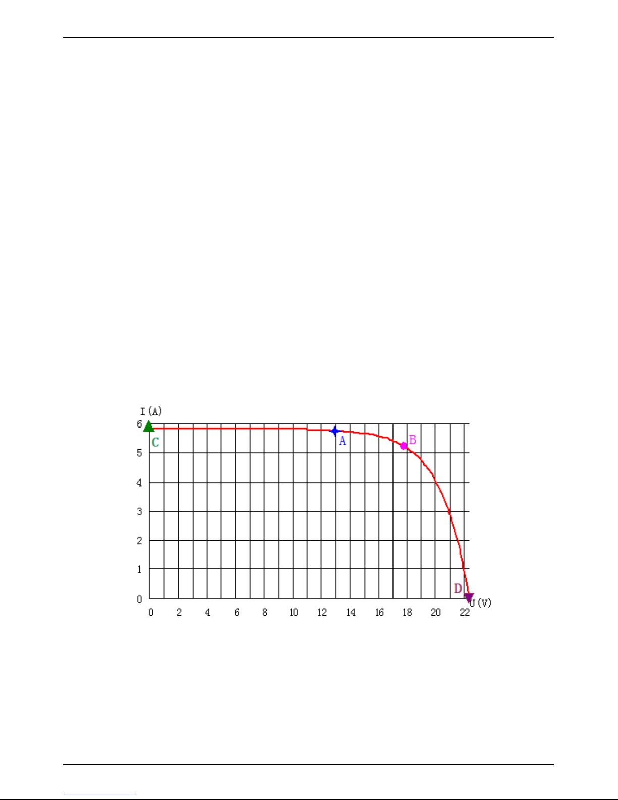
2.4 MPPT technology Instructions
Solar panels are nonlinear materials, and the output power is mainly
affected by illumination intensity, solar panels temperature and load
impedance. When the illumination intensity and solar panels temperature are
fixed, the output power of solar panels is only affected by load impedance.
Different load impedance will make the solar panels work at different point and
put out the different power. The following figure will mark the four working
points A, B, C, D, and the working point features as follows:
Working point D:
SMPPT Installation & Operation Manual Version 1.0
7
Output voltage is 22.3V, output power is 0W. This point is the open circuit
point of solar panels.
Working point C:
Output voltage is 0V, output power is 0W. This point is the short circuit
working point of solar panels.
Working point A:
Output voltage is 13V, output power is 74W. This working point is the state
when using normal controller, and the solar panels voltage is clamped to
13V by battery.
Working point B:
Output voltage is 17.6V, output power is 92W. This point is the state when
using MPPT controller. Because of using power conversion technology, the
solar panels voltage is not clamped by battery and still works at maximum
power point.
Compare working point A & B, it is easy to find using MPPT controller can
increase the using efficiency of solar panels. Compared to normal controller,
MPPT controller can generate more power.
Figure 2-4: Voltage-Current Curve
 Loading...