

MPP Solar PIP-HS, PIP-MS Installation Manual

1
1. Introduction
This inverter can be used in parallel with two different operation modes.
1. Parallel operation in single phase with up to 6 units. The supported maximum output power is
24KW/30KVA.
2. Maximum six units work together to support three-phase equipment. Four units support one phase
maximum. The supported maximum output power is 24KW/30KVA and one phase can be up to
16KW/20KVA.
NOTE: If this unit is bundled with share current cable and parallel cable, this inverter is default supported
parallel operation. You may skip section 3. If not, please purchase parallel kit and install this unit by following
instruction from professional technical personnel in local dealer.
2. Package Contents
In parallel kit, you will find the following items in the package:
Parallel board Parallel communication cable Current sharing cable
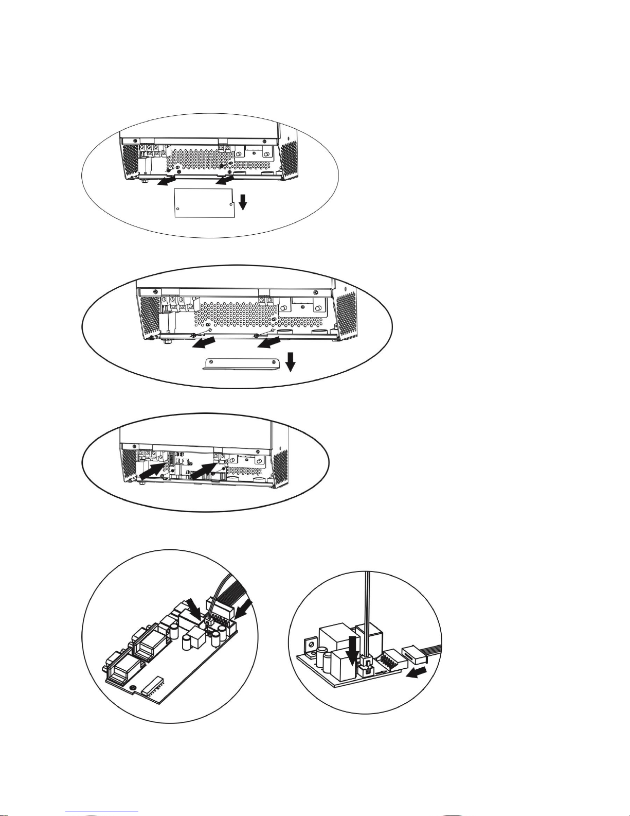
3. Parallel board installation
This installation steps are only applied to 4K/5K models.
Step 1: Remove wire cover by unscrewing all screws.
Step 2: Remove communication board by unscrewing two screws as below chart.
2
Step 3: Remove two screws as below chart and remove 2-pin and 14-pin cables. Take out the board under the
communication board.
Step 4: Remove two screws as below chart to take out cover of parallel communication.
Step 5: Install new parallel board with 2 screws tightly.
Step 6: Re-connect 2-pin and 14-pin to original position.
Parallel board Communication board
3
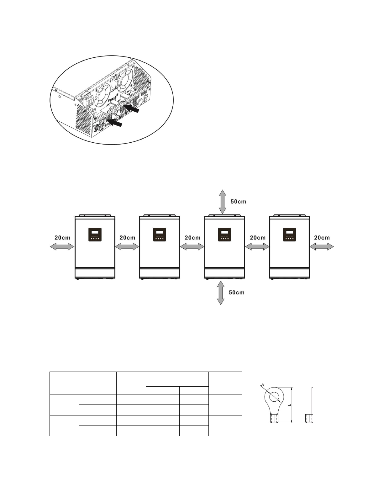
Step 7: Put communication board back to the unit.
Step 8: Put wire cover back to the unit. Now the inverter is providing parallel operation function.
4. Mounting the Unit
When installing multiple units, please follow below chart.
NOTE: For proper air circulation to dissipate heat, allow a clearance of approx. 20 cm to the side and approx.
50 cm above and below the unit. Be sure to install each unit in the same level.
5. Wiring Connection
The cable size of each inverter is shown as below:
Recommended battery cable and terminal size for each inverter:
Model
Wire Size
Ring Terminal
Torque
value
Cable
mm2
Dimensions
D (mm)
L (mm)
4KVA
1*4AWG
22
6.4
33.2
2~ 3 Nm
2*8AWG
14
6.4
29.2
5KVA
1*4AWG
22
6.4
33.2
2~ 3 Nm
2*8AWG
14
6.4
29.2
WARNING: Be sure the length of all battery cables is the same. Otherwise, there will be voltage difference
between inverter and battery to cause parallel inverters not working.
Ring terminal:

4
Recommended AC input and output cable size for each inverter:
Model
AWG no.
Torque
4KVA
10 AWG
1.4~1.6Nm
5KVA
8 AWG
1.4~1.6Nm
You need to connect the cables of each inverter together. Take the battery cables for example: You need to
use a connector or bus-bar as a joint to connect the battery cables together, and then connect to the battery
terminal. The cable size used from joint to battery should be X times cable size in the tables above. “X”
indicates the number of inverters connected in parallel.
Regarding AC input and output, please also follow the same principle.
CAUTION!! Please install the breaker at the battery and AC input side. This will ensure the inverter can be
securely disconnected during maintenance and fully protected from over current of battery or AC input. The
recommended mounted location of the breakers is shown in the figures in 5-1 and 5-2.
Recommended breaker specification of battery for each inverter:
Model
1 unit*
4KVA
80A/60VDC
5KVA
100A/60VDC
*If you want to use only one breaker at the battery side for the whole system, the rating of the breaker should
be X times current of 1 unit. “X” indicates the number of inverters connected in parallel.
Recommended breaker specification of AC input with single phase:
Model
2 units
3 units
4 units
5 units
6 units
4KVA
80A/230VAC
120A/230VAC
160A/230VAC
200A/230VAC
240A/230VAC
5KVA
100A/230VAC
150A/230VAC
200A/23VAC
250A/23VAC
300A/23VAC
Note1: Also, you can use 40A breaker (50A for 5KVA) for only 1 unit, and each inverter has a breaker at its AC
input.
Note2: Regarding three phase system, you can use 4 poles breaker, the rating is up to the current of the
phase which has the maximum units. Or you can follow the suggestion of note 1.
Recommended battery capacity
Inverter parallel numbers
2 3 4 5 6
Battery Capacity
400AH
600AH
800AH
1000AH
1200AH
WARNING! Be sure that all inverters will share the same battery bank. Otherwise, the inverters will transfer
to fault mode.
5
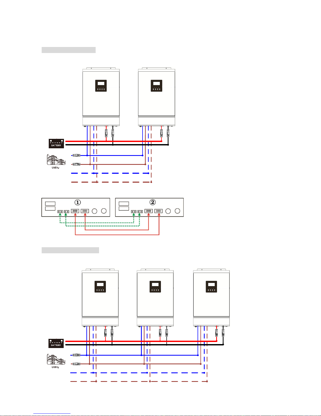
5-1. Parallel Operation in Single phase
Two inverters in parallel:
Power Connection
N
L
N
L
Load
Communication Connection
Three inverters in parallel:
Power Connection
N
L
N
L
Load
 Loading...