

MPP Solar 6000 Grid PV, Grid tied 6000 Installation And Operation Manual

1
6000 Grid PV
-
Inverter
Installation and Operation Manual
Version 1.0

2
Contents
Read this User Manual before you start ............................................................. 3
1. Safety Instructions ............................................................................................. 4
2. Limited Warranty ............................................................................................... 5
3. Overview ............................................................................................................. 6
3.1. Introducing the Grid PV System ........................................................ 6
3.2. Introducing the Grid PV System ........................................................ 7
3.3. Front Panel LEDs .............................................................................. 8
4. Features.............................................................................................................. 9
5. Installtion .......................................................................................................... 10
5.1. Inside
Inverter Package
....................................................... 10
5.2. Mounting your
Inverter
......................................................... 10
5.3. Connecting the AC-Output Cable .................................................... 16
5.4. Connecting the PV-Panel ................................................................ 19
5.5. Connecting to the connection unit ................................................... 20
5.6. Installation checklist......................................................................... 20
6. Operation the Inverter ................................ ................................ ....... 22
6.1. Auto-power ...................................................................................... 22
6.2. Operating Modes ............................................................................. 22
6.3. Using the LCD Display .................................................................... 24
6.4. Maximum Power Point Tracking (MPPT) ........................................ 28
6.5. LCD Display Messages ................................................................... 29
7. Communication Interface ............................................................................... 32
7.1. RS232 .............................................................................................. 32
7.2. Optional Communications Interface ................................................ 32
8. Troubleshooting ............................................................................................... 33
9. Specifications ................................ ................................................................ ... 35
10. Compliance of Standards ............................................................................. 36
11. Load Graph and Efficiency Graph .............................................................. 37
Appendix I: VDE Certification ............................................................................ 38

Brightens your future
3
Read this User Manual before you start
Congratulations on purchasing
6000
Grid PV
-
Inverter
from MPP SOLAR (referred to in this manual as “PV-Inverter”, or simply
the “device”). This PV-Inverter is a highly reliable product due to its
innovative design and perfect quality control. The device is dedicated to
high-demand, grid-linked PV systems.
This manual contains important information regarding installation and
safe operation of this unit. Be sure to read this manual carefully before
using your PV-Inverter.
If you encounter any difficulties during installation or operation, please
refer to this manual before contacting your local dealer or
representative. To obtain the latest manual and product information,
please visit our web site:
http://www.mppsolar.com
Brightens your future
4
1. Safety Instructions
1. Risk of Electric Shock:
Alternating Current (AC) and Direct Current (DC) sources
are terminated in this device. To prevent risk of electric
shock during maintenance or installation please ensure
that all AC and DC terminals are disconnected.
2. Handling your PV-Inverter:
The PV-Inverter should only be handled by qualified
service personnel. When the PV-panel is exposed to
sunlight and connected to the device, it generates a DC
voltage charging the DC link capacitors.
After disconnecting the PV-Inverter from the power supply
and PV-panel, electrical charge can still reside in the DC
link capacitors. Qualified personnel should allow at least 60
minutes after disconnecting, before handling the device.
3. Public Utility only:
The PV-Inverter is designed to feed AC power directly to
the public utility power grid. Do not connect the AC-output
of this device to any private AC equipment.
4. Beware of Hot Surfaces:
Although designed to meet international safety standards,
the PV- Inverter can become hot during operation. Do not
touch the heat-sink or peripheral surfaces during or shortly
after operation.

Brightens your future
5
2. Limited Warranty
The 6000 PV-Inverter comes with a 5 year warranty. An optional
extended warranty may be available by special request before delivery.
This warranty covers all defects due to design, manufacturing and
components. This warranty does not cover damages resulting from:
Improper transportation and delivery
Improper installation
Unauthorized modification, testing or repairing
Usage beyond that described in this manual
Application beyond the scope of safety standards such as VDE,
UL etc.
Acts of nature, such as lightening, fire, storm etc.
Repairs and/or replacement of parts or the device are made at the
manufacturers discretion. Defective parts or malfunction discovered
during installation should be presented in a written report for
confirmation before applying for replacement or repair. The damage
report must be issued within 5 working days after receiving the
PV-Inverter. MPP SOLAR is not responsible for damages beyond the
scope of this warranty.

Brightens your future
6
3. Overview
3.1. Introducing the Grid PV System
The Grid PV System is mainly composed of 4 parts: the PV-panels, the
PV-Inverter, the AC-Connection Unit (the connection Interface) and a
connection to the Public Utility.
When a PV-panel is exposed to sunlight and connected to an inverter, it
generates DC power. The PV-Inverter converts DC to AC and feeds in
to the Public Utility via the AC-Connection unit.
AC-Conne
ction Unit
Inverter
Feeding AC power to Public Utility only
Grid (Public Utility)
AC
Output
PV-Panel
DC-Input
+ _
Brightens your future
7
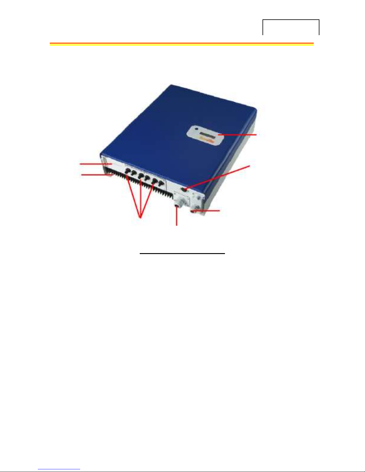
3.2. Introducing the Grid PV System
6000 Inverter
(1) Connection Panel: The connection panel contains DC and AC
terminals, and communication ports as detailed below.
(2) Heat-sink: Part to dissipate heat produced by the inverter
(3) 3 pairs of DC-input terminals: Each input pair consists of positive
and negative terminals. Refer to Installation Section for set-up
information.
(4) AC-Output: Delivering AC to the Public Utility.
(5) Optional Communication Slot and Cover: An optional port to
extend the communication interface, for example connecting an
RS485 card. The port is protected by a water-proof cover.
(6) RS232 Port: Interface allows communication with computer with
RS232 serial port.
(7) LCD Display: Device to display inverter operation status.
(1) Connection
Panel
(2) Heat-sink
(3) 3-pairs of DC inputs
(4) AC Output
(5) Optional Communication
Port and Cover
(6) RS232 Connector
(7) Front LCD Display
Panel
Brightens your future
8
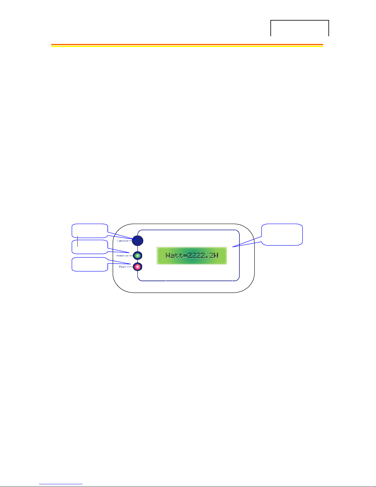
3.3. Front Panel LEDs
There are 2 LED’s on Grid tied 6000, one is green and the other is
red. Normally, only the green LED will turn on during operation.
Their indicated status are explained as follows:
Power on (green LED): It lights when Inverter
is running. The only
condition it will be dark is no power provided to
inverter. In
this case, Inverter
is in shutdown mode.
Fault (red LED): Once the LED lights, it means inverter is in “fault”
or “failure” condition. To see the conditions, please refer to section
8:
LCD (Liquid
Crystal Display)
Function Key
Power-on LED
Fault LED

Brightens your future
9
4. Features
Very high conversion efficiency (>96%)
3 MPP (Maximum Power Point) trackers, independent or parallel
operation
IP65 compliant for outdoor application
Embedded LCD, displaying status and system information
Fanless design, quiet operation
Stylish design
Compact and unobtrusive
High reliability
Easy installation
Maintenance free
Standard RS232, optional RS485 and others
Embedded ENS, complying with VDE 0126
Internal GFCI (Ground Fault Current Interrupter)
Brightens your future
10
5. Installation
5.1. Inside Grid tied 6000 Package
The following items are included with your Inverter 6000 Package:
(1) Inverter 6000 PV-Inverter
(2) Installation and Operation Manual
(3) 4 Mounting Screws and 4 Snap Bushings
(4) 2 Safety-lock screws
(5) 3-hole Rubber Bushing
(6) Mounting Bracket
5.2. Mounting your Inverter 6000
Suggestions before mounting
To obtain optimal results from your PV-Inverter, please
consider the following guidelines before installing the device:
DDoo nnoott eexxppoossee tthhee PPVV--IInnvveerrtteerr ttoo ddiirreecctt ssuunnlliigghhtt.. DDiirreecctt
ssuunnlliigghhtt iinnccrreeaasseess tthhee iinntteerrnnaall tteemmppeerraattuurree tthhaatt mmaayy rreedduuccee
ccoonnvveerrssiioonn eeffffiicciieennccyy..
Check the ambient temperature of installation is within specified range
-20 ~ +55C.
The AC grid voltage is between 196 and 253VAC, 50/60Hz.
Electric utility company has approved the grid connection.
Qualified personnel are performing the installation.
Adequate convection space surrounds the inverter.
Inverter is being installed away from explosive vapors.

Brightens your future
11
No flammable items are to be near the inverter.
Brightens your future
12
MMoouunnttiinngg
tto
o
tthhe
e
wwaalll
l
1. Choose a dry place, out of direct sunlight with ambient
temperature between 0 and 40°C.
2. Select a wall or solid, vertical surface which is strong enough to
support the inverter.
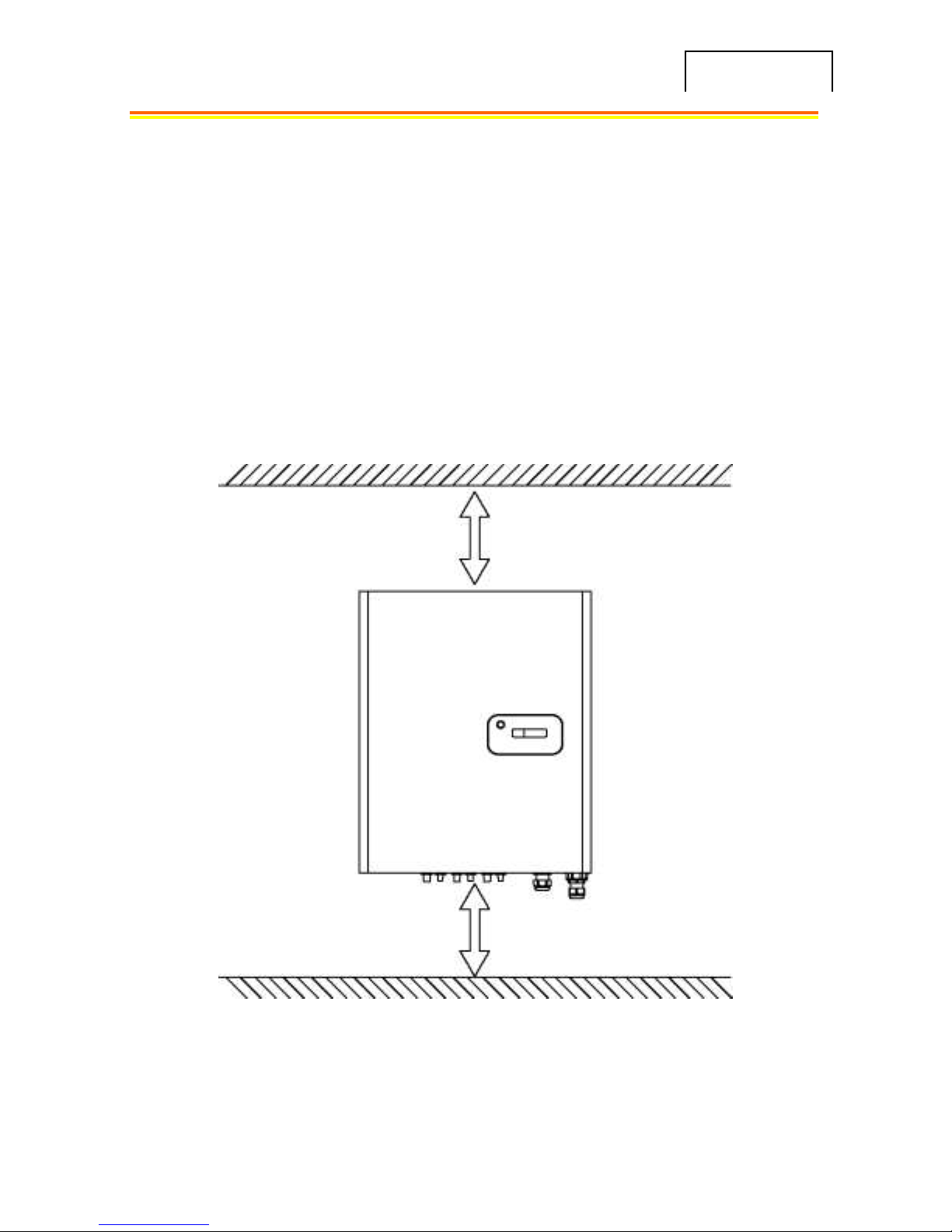
3. The PV-Inverter requires adequate cooling space for heat
dispersal. Reserve at least 20 cm above and below the inverter.
Minimum space 20 cm
Minimum space 20 cm
 Loading...