

MPP Solar 3KW, 5KW User Manual

3KW/5KW
INVERTER / CHARGER
Version: 1.0
User Manual
PIP-MK SERIES

Table Of Contents
ABOUT THIS MANUAL ...................................................................................................................................... 1
Purpose ............................................................................................................................................................ 1
Scope ............................................................................................................................................................... 1
SAFETY INSTRUCTIONS ................................................................................................................................... 1
INTRODUCTION ................................................................................................................................................. 2
Features ........................................................................................................................................................... 2
Basic System Architecture ............................................................................................................................... 2
Product Overview ............................................................................................................................................. 3
INSTALLATION ................................................................................................................................................... 4
Unpacking and Inspection................................................................................................................................ 4
Preparation ...................................................................................................................................................... 4
Mounting the Unit ............................................................................................................................................. 4
Battery Connection .......................................................................................................................................... 5
AC Input/Output Connection ............................................................................................................................ 6
PV Connection ................................................................................................................................................. 7
Final Assembly ................................................................................................................................................. 8
Remote Display Panel Installation ................................................................................................................... 9
Communication Connection ........................................................................................................................... 10
Dry Contact Signal ......................................................................................................................................... 10
OPERATION ...................................................................................................................................................... 11
Power ON/OFF .............................................................................................................................................. 11
Operation and Display Panel ......................................................................................................................... 11
LCD Display Icons ......................................................................................................................................... 12
LCD Setting .................................................................................................................................................... 14
Display Setting ............................................................................................................................................... 22
Operating Mode Description .......................................................................................................................... 27
Fault Reference Code .................................................................................................................................... 29
Warning Indicator ........................................................................................................................................... 29
Battery Equalization ....................................................................................................................................... 30
SPECIFICATIONS ............................................................................................................................................. 32
Table 1 Line Mode Specifications ................................................................................................................... 32
Table 2 Battery Mode Specifications .............................................................................................................. 33
Table 3 Charge Mode Specifications .............................................................................................................. 34
Table 4 ECO/Bypass Mode Specifications ....................................................................................................... 35
TROUBLE SHOOTING ..................................................................................................................................... 36
Appendix I: Approximate Back-up Time Table ............................................................................................. 37

1
ABOUT THIS MANUAL
Purpose
This manual describes the assembly, installation, operation and troubleshooting of this unit. Please read
this manual carefully before installations and operations. Keep this manual for future reference.
Scope
This manual provides safety and installation guidelines as well as information on tools and wiring.
SAFETY INSTRUCTIONS
WARNING: This chapter contains important safety and operating instructions. Read and
keep this manual for future reference.
1. Before using the unit, read all instructions and cautionary markings on the unit, the batteries and all
appropriate sections of this manual.
2. CAUTION --To reduce risk of injury, charge only deep-cycle lead acid type rechargeable batteries.
Other types of batteries may burst, causing personal injury and damage.
3. Do not disassemble the unit. Take it to a qualified service center when service or repair is required.
Incorrect re-assembly may result in a risk of electric shock or fire.
4. To reduce risk of electric shock, disconnect all wirings before attempting any maintenance or cleaning.
Turning off the unit will not reduce this risk.
5. CAUTION – Only qualified personnel can install this device with battery.
6. NEVER charge a frozen battery.
7. For optimum operation of this inverter/charger, please follow required spec to select appropriate cable
size. It’s very important to correctly operate this inverter/charger.
8. Be very cautious when working with metal tools on or around batteries. A potential risk exists to drop
a tool to spark or short circuit batteries or other electrical parts and could cause an explosion.
9. Please strictly follow installation procedure when you want to disconnect AC or DC terminals. Please
refer to INSTALLATION section of this manual for the details.
10. Fuses are provided as over-current protection for the battery supply.
11. GROUNDING INSTRUCTIONS -This inverter/charger should be connected to a permanent grounded
wiring system. Be sure to comply with local requirements and regulation to install this inverter.
12. NEVER cause AC output and DC input short circuited. Do NOT connect to the mains when DC input
short circuits.
13. Warning!! Only qualified service persons are able to service this device. If errors still persist after
following troubleshooting table, please send this inverter/charger back to local dealer or service center
for maintenance.
2
INTRODUCTION
This is a multi-function inverter/charger, combining functions of inverter, MPPT solar charger and battery
charger to offer uninterruptible power support with portable size. Its comprehensive LCD display offers
user-configurable and easy-accessible button operation such as battery charging current, AC/solar charger
priority, and acceptable input voltage based on different applications.
Features
Pure sine wave inverter
Built-in MPPT solar charge controller
Configurable input voltage range for home appliances and personal computers via LCD setting
Configurable battery charging current based on applications via LCD setting
Configurable AC/Solar Charger priority via LCD setting
Compatible to mains voltage or generator power
Auto restart while AC is recovering
Overload/ Over temperature/ short circuit protection
Smart battery charger design for optimized battery performance
Cold start function
Zero-transfer Time
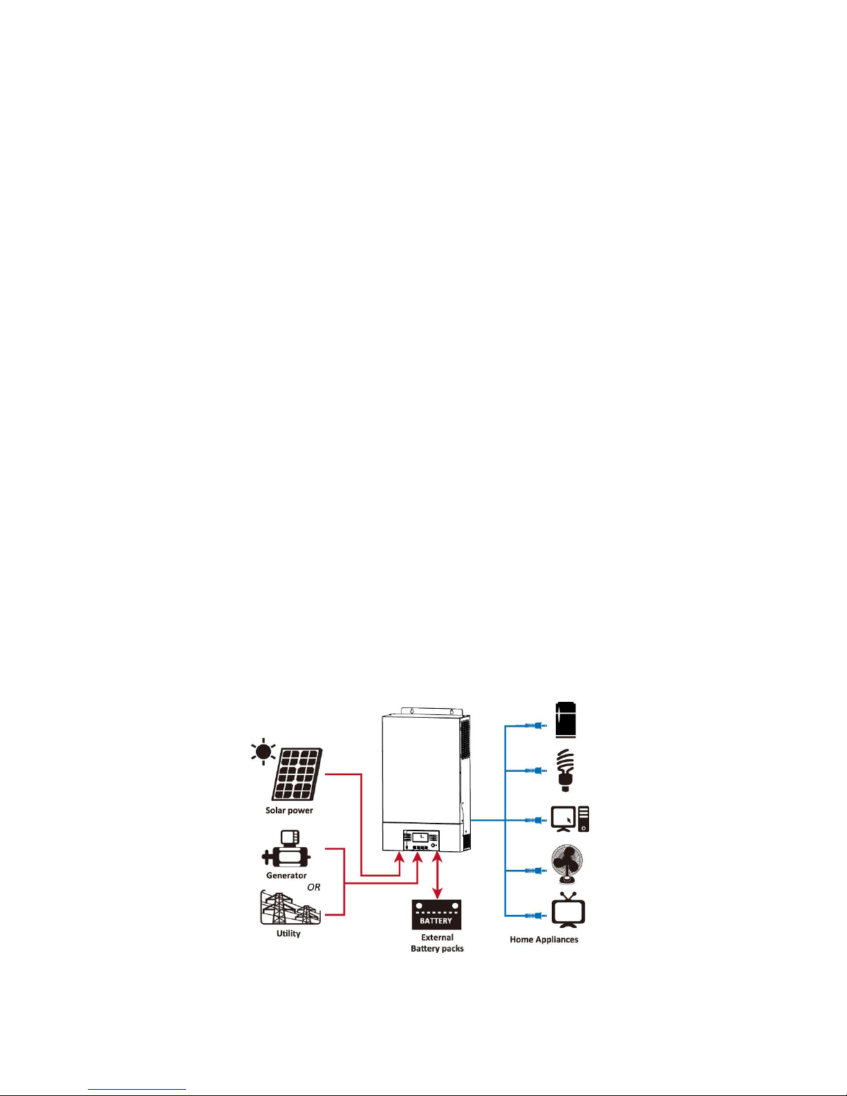
Basic System Architecture
The following illustration shows basic application for this inverter/charger. It also includes following devices to
have a complete running system:
Generator or Utility.
PV modules
Consult with your system integrator for other possible system architectures depending on your requirements.
This inverter can power all kinds of appliances in home or office environment, including motor-type appliances
such as tube light, fan, refrigerator and air conditioner.
Figure 1 Hybrid Power System
3
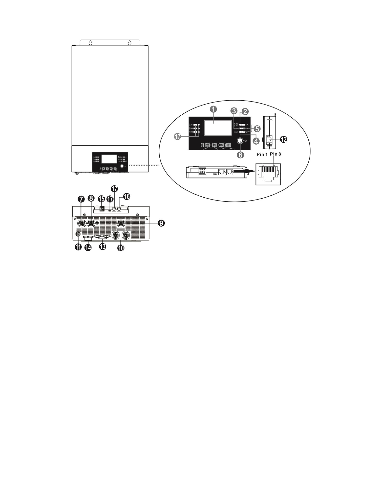
Product Overview
1. LCD display
2. Status indicator
3. Charging indicator
4. Fault indicator
5. Function keys (Please refer to operation chapter for the detailed operation)
6. Power on/off switch
7. AC input
8. AC output
9. PV input
10. Battery input
11. Circuit breaker
12. Remote LCD panel communication port
13. Parallel communication cable (only for parallel model)
14. Current sharing cable (only for parallel model)
15. Dry contact
16. RS-232 communication port
17. Reserved for future use
NOTE: For parallel model installation and operation, please check separate parallel installation guide for the
details.
4
INSTALLATION
Unpacking and Inspection
Before installation, please inspect the unit. Be sure that nothing inside the package is damaged. You should
have received the following items inside of package:
The unit x 1
User manual x 1
Communication cable x 1
Software CD x 1
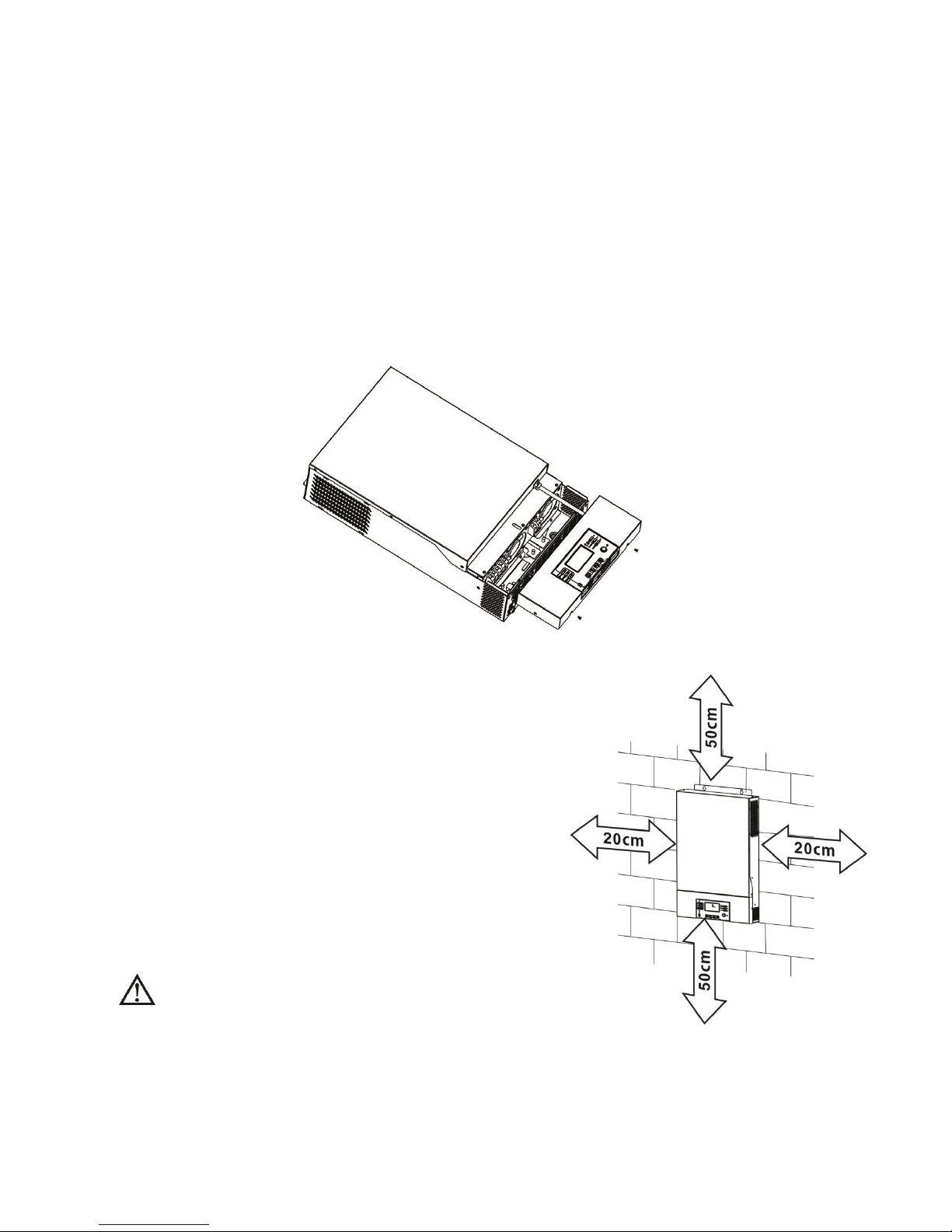
Preparation
Before connecting all wirings, please take off bottom cover by removing two screws as shown below.
Mounting the Unit
Consider the following points before selecting where to install:
Do not mount the inverter on flammable construction materials.
Mount on a solid surface
Install this inverter at eye level in order to allow the LCD display
to be read at all times.
The ambient temperature should be between 0°C and 55°C to
ensure optimal operation.
The recommended installation position is to be adhered to the
wall vertically.
Be sure to keep other objects and surfaces as shown in the
right diagram to guarantee sufficient heat dissipation and to
have enough space for removing wires.
SUITABLE FOR MOUNTING ON CONCRETE OR
OTHER NON-COMBUSTIBLE SURFACE ONLY.
5
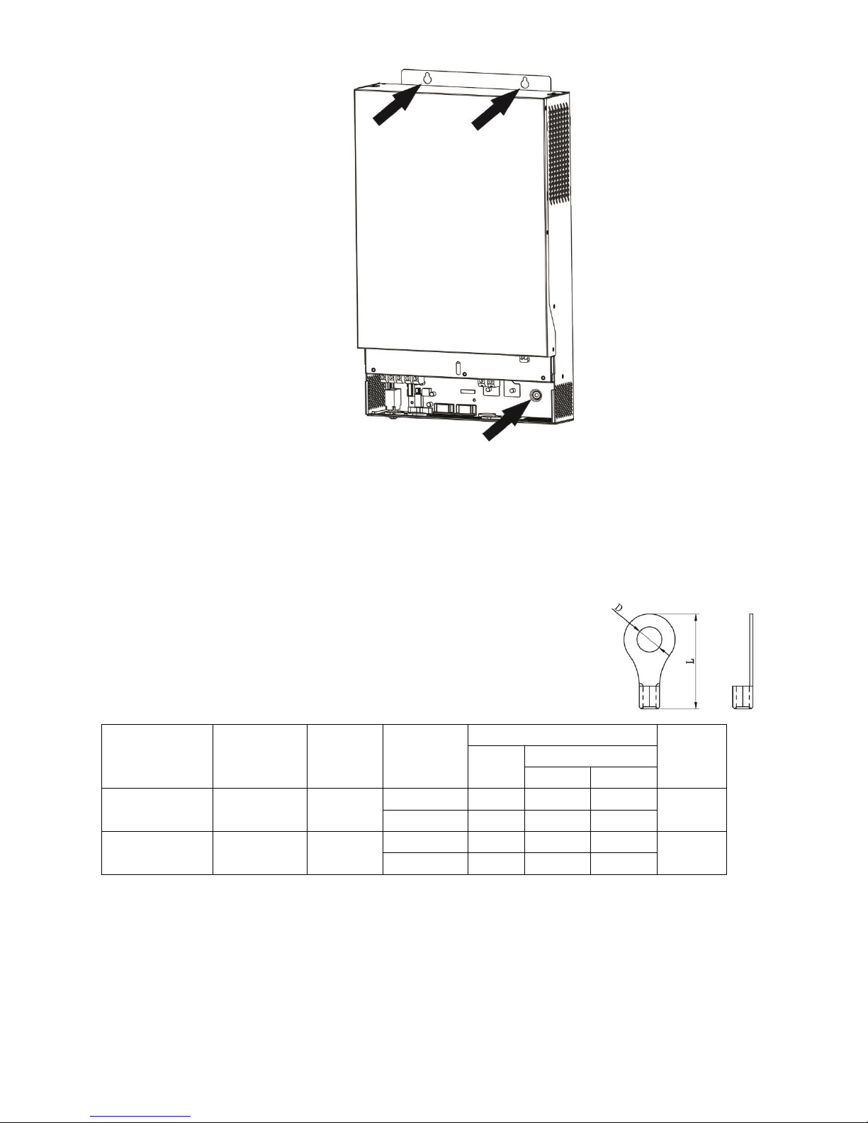
Install the unit by screwing three screws. It’s recommended to use M4 or M5 screws.
Battery Connection
CAUTION: For safety operation and regulation compliance, it’s requested to install a separate DC over-current
protector or disconnect device between battery and inverter. It may not be requested to have a disconnect
device in some applications, however, it’s still requested to have over-current protection installed. Please refer
to typical amperage in below table as required fuse or breaker size.
WARNING! All wiring must be performed by a qualified personnel.
WARNING! It's very important for system safety and efficient operation to use
appropriate cable for battery connection. To reduce risk of injury, please use the
proper recommended cable and terminal size as below.
Recommended battery cable and terminal size:
Model
Typical
Amperage
Battery
Capacity
Wire Size
Ring Terminal
Torque
Value
Cable
mm2
Dimensions
D (mm)
L (mm)
3KW
200A
200AH
1*1/0AWG
60
6.4
49.7
2~3 Nm
2*4AWG
44
6.4
49.7
5KW
200A
200AH
1*1/0AWG
60
6.4
49.7
2~3 Nm
2*4AWG
44
6.4
49.7
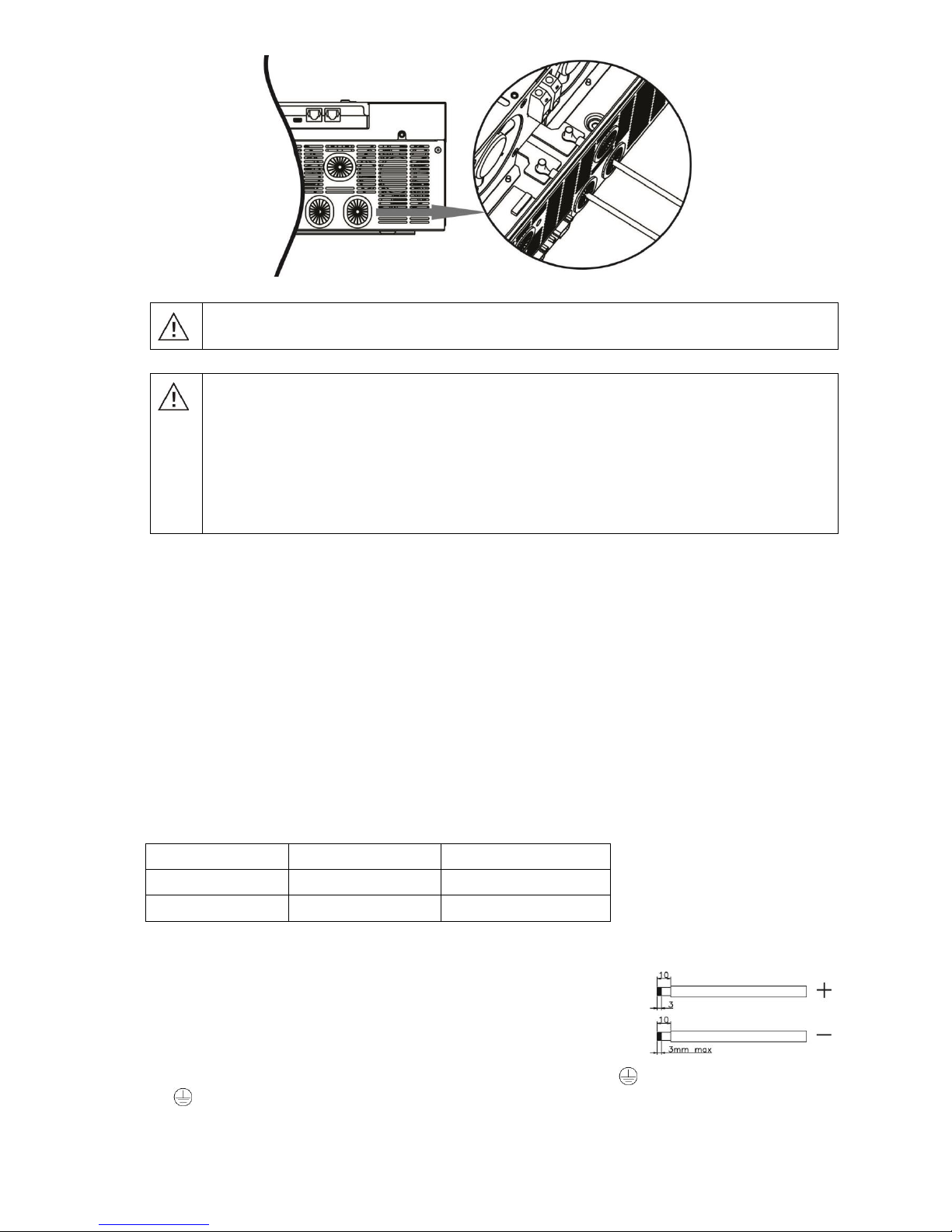
Please follow below steps to implement battery connection:
1. Assemble battery ring terminal based on recommended battery cable and terminal size.
2. Connect all battery packs as units requires. It’s suggested to connect at least 200Ah capacity battery for
3KW model and at least 200Ah capacity battery for 5KW model.
3. Insert the ring terminal of battery cable flatly into battery connector of inverter and make sure the bolts are
tightened with torque of 2-3 Nm. Make sure polarity at both the battery and the inverter/charge is correctly
connected and ring terminals are tightly screwed to the battery terminals.
Ring terminal:
6
WARNING: Shock Hazard
Installation must be performed with care due to high battery voltage in series.
CAUTION!! Do not place anything between the flat part of the inverter terminal and the ring
terminal. Otherwise, overheating may occur.
CAUTION!! Do not apply anti-oxidant substance on the terminals before terminals are
connected tightly.
CAUTION!! Before making the final DC connection or closing DC breaker/disconnector, be sure
positive (+) must be connected to positive (+) and negative (-) must be connected to negative
(-).
AC Input/Output Connection
CAUTION!! Before connecting to AC input power source, please install a separate AC breaker between
inverter and AC input power source. This will ensure the inverter can be securely disconnected during
maintenance and fully protected from over current of AC input. The recommended spec of AC breaker is 30A
for 3KW, 50A for 5KW.
CAUTION!! There are two terminal blocks with “IN” and “OUT” markings. Please do NOT mis-connect input
and output connectors.
WARNING! All wiring must be performed by a qualified personnel.
WARNING! It’s very important for system safety and efficient operation to use appropriate cable for AC input
connection. To reduce risk of injury, please use the proper recommended cable size as below.
Suggested cable requirement for AC wires
Model
Gauge
Torque Value
3KW
10 AWG
1.2~ 1.6 Nm
5KW
8 AWG
1.4~ 1.6Nm
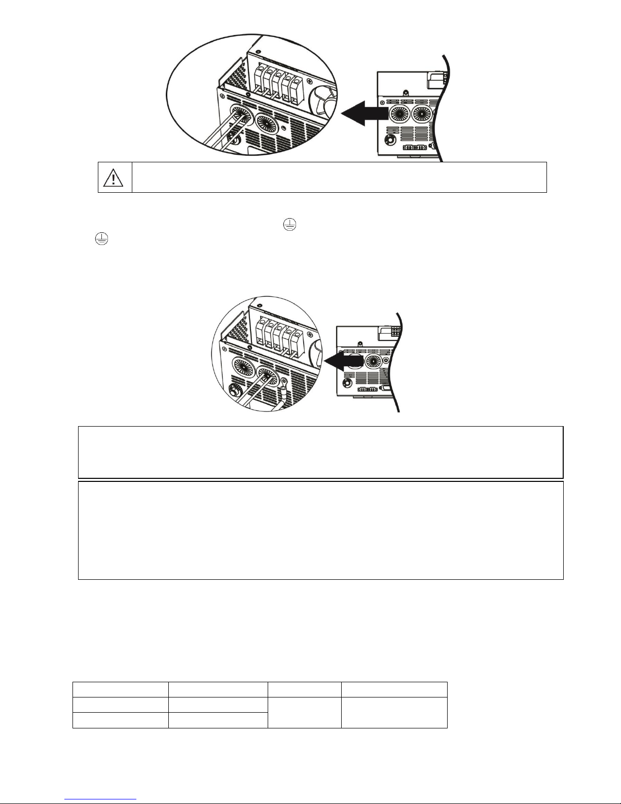
Please follow below steps to implement AC input/output connection:
1. Before making AC input/output connection, be sure to open DC protector or
disconnector first.
2. Remove insulation sleeve 10mm for six conductors. And shorten phase L and
neutral conductor N 3 mm.
3. Insert AC input wires according to polarities indicated on terminal block and
tighten the terminal screws. Be sure to connect PE protective conductor ( ) first.
→Ground (yellow-green)
L→LINE (brown or black)
N→Neutral (blue)
7
WARNING:
Be sure that AC power source is disconnected before attempting to hardwire it to the unit.
4. Then, insert AC output wires according to polarities indicated on terminal block and tighten terminal screws.
Be sure to connect PE protective conductor ( ) first.
→Ground (yellow-green)
L→LINE (brown or black)
N→Neutral (blue)
5. Make sure the wires are securely connected.
PV Connection
CAUTION: Before connecting to PV modules, please install separately a DC circuit breaker between inverter
and PV modules.
WARNING! All wiring must be performed by a qualified personnel.
WARNING! It'’ very important for system safety and efficient operation to use appropriate cable for PV module
connection. To reduce risk of injury, please use the proper recommended cable size as below.
Model
Typical Amperage
Cable Size
Torque
3KW
60A
6 AWG
1.2~1.6 Nm
5KW
80A
CAUTION: Important
Be sure to connect AC wires with correct polarity. If L and N wires are connected reversely, it may cause
utility short-circuited when these inverters are worked in parallel operation.
CAUTION: Appliances such as air conditioner are required at least 2~3 minutes to restart because it’s required
to have enough time to balance refrigerant gas inside of circuits. If a power shortage occurs and recovers in a
short time, it will cause damage to your connected appliances. To prevent this kind of damage, please check
manufacturer of air conditioner if it’s equipped with time-delay function before installation. Otherwise, this
inverter/charger will trig overload fault and cut off output to protect your appliance but sometimes it still causes
internal damage to the air conditioner.
8
PV Module Selection:
When selecting proper PV modules, please be sure to consider below parameters:
1. Open circuit Voltage (Voc) of PV modules not exceeds max. PV array open circuit voltage of inverter.
2. Open circuit Voltage (Voc) of PV modules should be higher than min. battery voltage.
Solar Charging Mode
INVERTER MODEL
3KW
5KW
Max. PV Array Open Circuit Voltage
145Vdc
PV Array MPPT Voltage Range
30~115Vdc
60~115Vdc
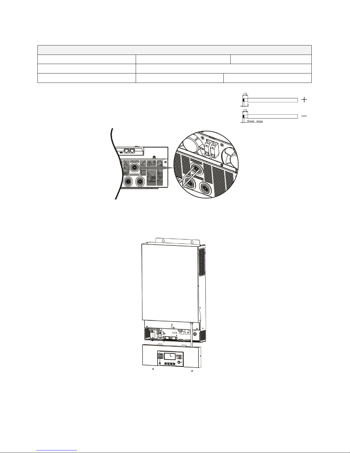
Please follow below steps to implement PV module connection:
1. Remove insulation sleeve 10 mm for positive and negative conductors.
2. Check correct polarity of connection cable from PV modules and PV input
connectors. Then, connect positive pole (+) of connection cable to positive
pole (+) of PV input connector. Connect negative pole (-) of connection
cable to negative pole (-) of PV input connector.
3. Make sure the wires are securely connected.
Final Assembly
After connecting all wirings, please put bottom cover back by screwing two screws as shown on the right chart.
9
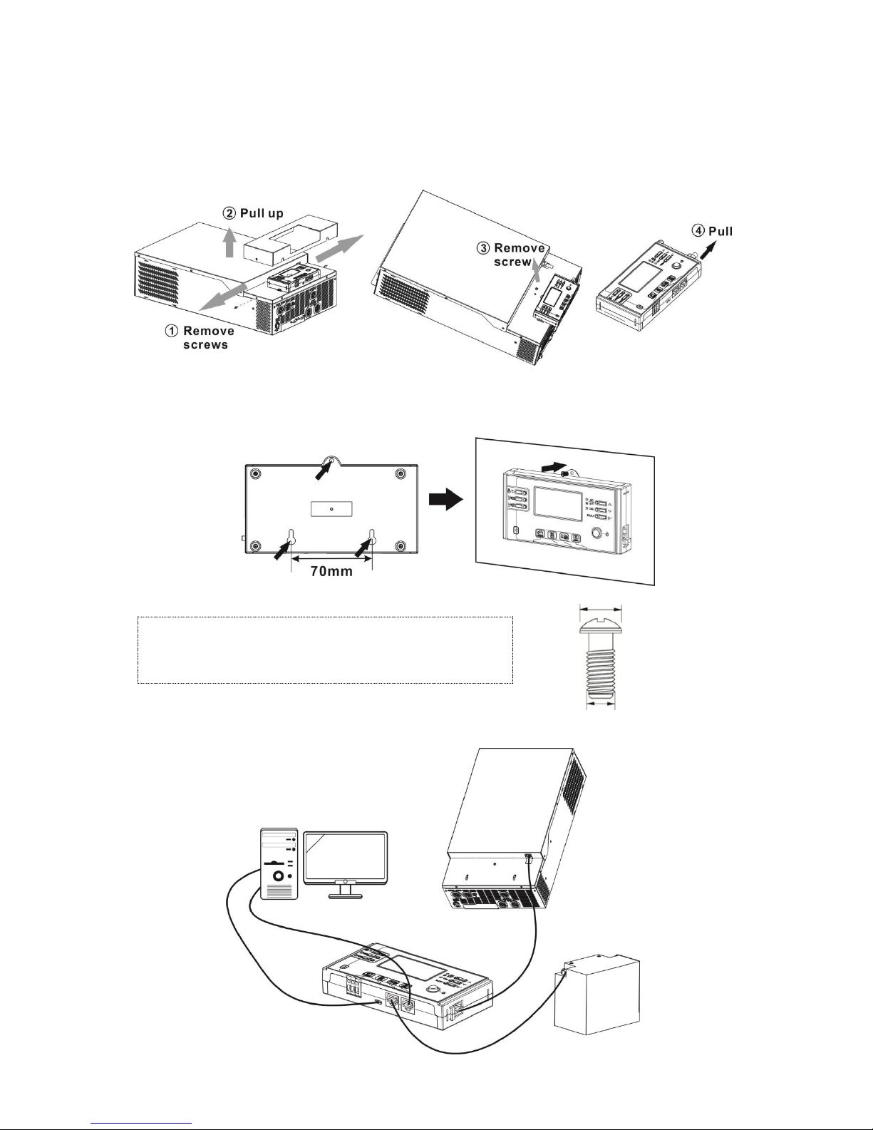
Remote Display Panel Installation
The LCD panel can be removable and installed in a remote site with an optional communication cable. Please
follow below steps to implement this remote panel installation.
Step 1. Loosen the screw on the two sides of bottom case and push up the case cover. Then, remove screw on
the top of the display panel. Now, the display can be removed from the bottom case. Then, pull out the cable
from the remote communication port.
Step 2. Drill two holes in the marked locations with two screws as shown below chart. Place the panel on the
surface and align the mounting holes with the two screws. Then, use one more screw on the top to fix the panel
to the wall and check if the remote panel is firmly secured.
Note: Installation to the wall should be implemented with
the proper screws. Refer chart for recommended spec of
screws.
Step 3. Connect LCD panel to the inverter with an optional RJ45 communication cable as below chart.
M3
Ø 5-Ø 9
10
Communication Connection
Serial Connection
Please use supplied communication cable to connect to inverter and PC. Insert bundled CD into a computer and
follow on-screen instruction to install the monitoring software. For the detailed software operation, please
check user manual of software inside of CD.
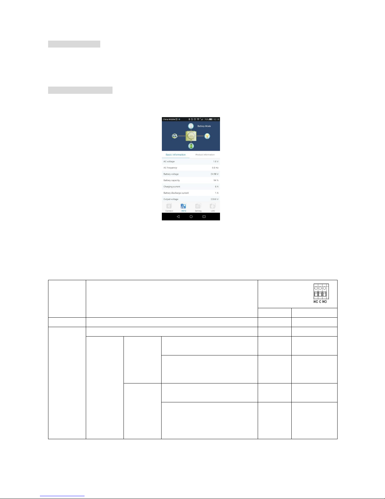
Bluetooth Connection
This series is built in Bluetooth technology. You may simply go to google play to install “WatchPower”. It allows
wireless communication up to 6~7m in an open space.
Dry Contact Signal
There is one dry contact (3A/250VAC) available on the rear panel. It could be used to deliver signal to external
device when battery voltage reaches warning level.
Unit Status
Condition
Dry contact port:
NC & C
NO & C
Power Off
Unit is off and no output is powered.
Close
Open
Power On
Output is powered from Utility.
Close
Open
Output is
powered
from
Battery
power or
Solar
energy.
Program 01
set as USB
(utility first)
Battery voltage < Low DC warning
voltage
Open
Close
Battery voltage > Setting value in
Program 13 or battery charging
reaches floating stage
Close
Open
Program 01
is set as
SBU (SBU
priority) or
SUB (solar
first)
Battery voltage < Setting value in
Program 12
Open
Close
Battery voltage > Setting value in
Program 13 or battery charging
reaches floating stage
Close
Open
 Loading...