

Page 1
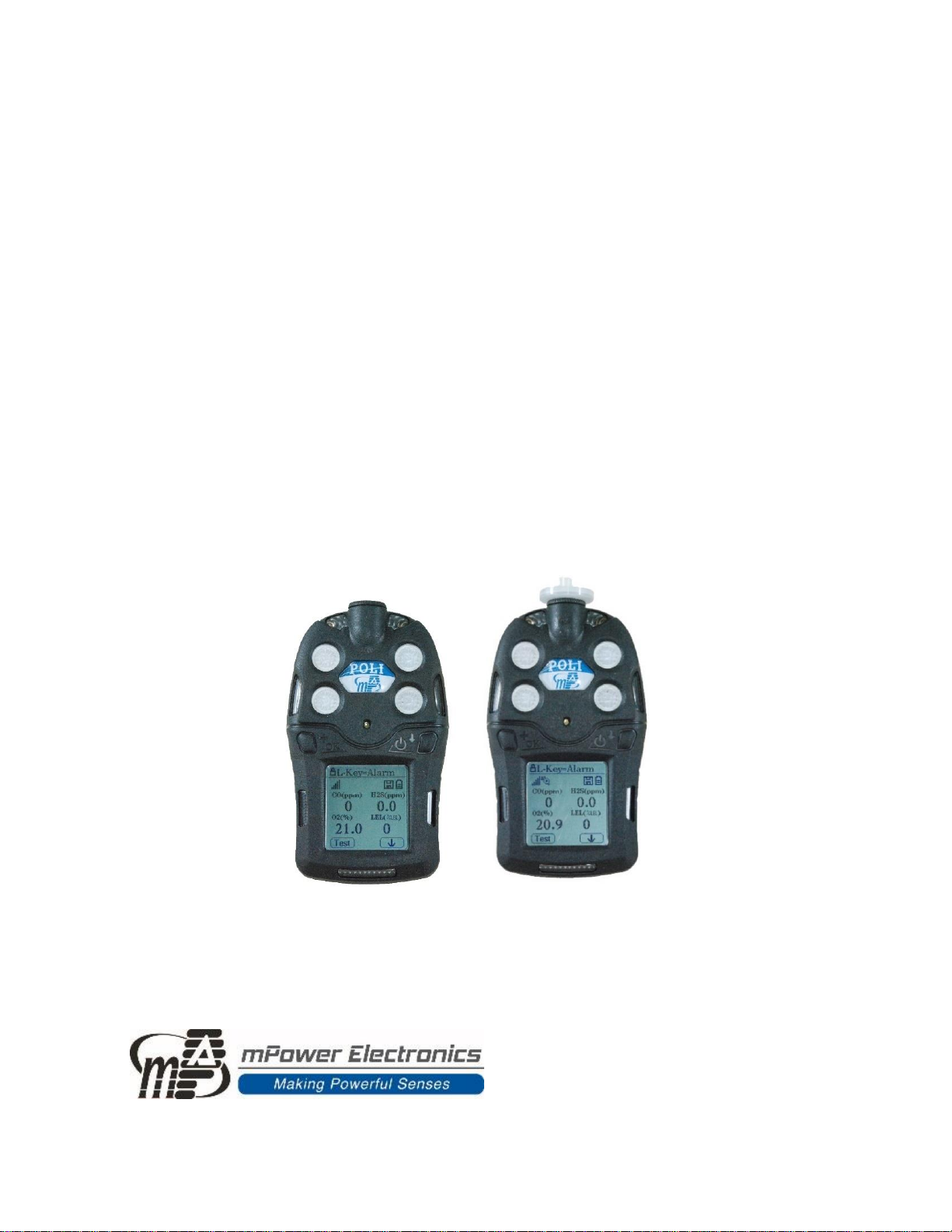
POLI
Multi-Gas Detectors
MP400 & MP400P
User’s Guide
Rev 1.11
July, 2019
Page 2

POLI User’s Guide
1
Contents
1. General Information ..............................................................................................................5
1.1 Main Features ............................................................................................................................................................ 5
2. Battery ................................................................................................................................6
2.1 Battery Charging........................................................................................................................................................ 6
2.2 Battery Status ............................................................................................................................................................ 6
2.3 Battery Replacement ................................................................................................................................................. 6
3. User Interface.......................................................................................................................7
3.1 Displays and Keys....................................................................................................................................................... 7
4. Basic Operation ....................................................................................................................9
4.1 Turning On.................................................................................................................................................................. 9
4.2 Turning Off ................................................................................................................................................................. 9
4.3 Active Sensor Displays ............................................................................................................................................. 10
4.4 Pump Status ............................................................................................................................................................. 10
4.5 Alarm Testing ........................................................................................................................................................... 11
4.6 Main User Menu ...................................................................................................................................................... 11
5. Configuration Mode ............................................................................................................ 12
5.1 Entering Configuration Mode ................................................................................................................................. 12
5.2 Exiting Configuration Mode .................................................................................................................................... 12
5.3 Navigating Configuration Mode to Edit Parameters............................................................................................. 13
5.4 Calibration and Bump Testing ................................................................................................................................ 16
5.5 Measurement........................................................................................................................................................... 20
5.6 Alarm Settings.......................................................................................................................................................... 21
5.7 Datalog ..................................................................................................................................................................... 23
5.8 Monitor Set-up ......................................................................................................................................................... 23
5.9 Wireless Set-up ........................................................................................................................................................ 25
6. Data Communication ........................................................................................................... 26
6.1 Connecting and Configuring.................................................................................................................................... 26
6.2 Datalog Retrieval ..................................................................................................................................................... 27
6.3 Real-Time Data ........................................................................................................................................................ 28
7. Maintenance ...................................................................................................................... 29
7.1 Year of Manufacture ............................................................................................................................................... 29
7.2 Replacing Filters....................................................................................................................................................... 29
7.3 Removing/Cleaning/Replacing Sensor Modules.................................................................................................... 29
7.4 Replacing Pump or Battery ..................................................................................................................................... 30
8. Troubleshooting.................................................................................................................. 31
9. Technical Specifications ....................................................................................................... 32
Recommended Gas Span Concentrations .................................................................................................................... 33
Technical Support and mPower Contacts.................................................................................... 34
Page 3
POLI User’s Guide
2
Read Before Operating
This manual must be carefully read by all individuals who have or will have the responsibility of
using, maintaining or servicing this product. The product will perform as designed only if it is
used, maintained and serviced in accordance with the manufacturer’s instructions. The user
should understand how to set the correct parameters and interpret the obtained results.
CAUTION!
•
REMOVE MONITOR COVER ONLY IN AREA KNOWN TO BE NON-HAZARDOUS.
•
RECHARGE BATTERY ONLY IN AN AREA KNOWN TO BE NON- HAZARDOUS.
•
USE ONLY mPOWER’S RECHARGEABLE LITHIUM BATTERY P/N M004-3002-000.
•
USE OF NON-mPower COMPONENTS WILL VOID THE WARRANTY AND CAN
COMPROMISE THE SAFE PERFORMANCE OF THIS PRODUCT
SUBSTITUTION OF COMPONENTS MAY IMPACT INTRINSIC SAFETY.
CAUTION: HIGH OFF-SCALE READINGS MAY INDICATE AN EXPLOSIVE
CONCENTRATION. ANY RAPID UP-SCALE READING FOLLOWED BY A DECLINING
OR ERRATIC READING MAY INDICATE A GAS CONCENTRATION BEYOND UPPER
SCALE LIMIT WHICH MAY BE HAZARDOUS.
ATTENTION: DES LECTURES SUPÉRIEURES A L’ÉCHELLE PEUVENT INDIQUER
DES CONCENTRATIONS EXPLOSIVES. TOUTE LECTURE RAPIDE ET POSITIVE,
SUIVIE D’UNE BAISSE SUBITE AU ERRATIQUE DE LA VALEUR, PEUT INDIQUER
UNE CONCENTRATION DE GAZ HORS GAMME DE DÉTECTION QUI PEUT ÊTRE
DANGEREUSE.
WARNINGS
ONLY THE COMBUSTIBLE GAS DETECTION PORTION OF THIS INSTRUMENT HAS
BEEN ASSESSED FOR PERFORMANCE.
UNIQUMENT, LA PORTION POUR DÉTECTOR LES GAZ COMBUSTIBLES DE CET
INSTRUMENT A ÉTÉ ÉVALUÉE.
CAUTION: BEFORE EACH DAY’S USE, THE SENSITIVITY OF THE COMBUSTIBLE
GAS SENSOR MUST BE TESTED ON A KNOWN CONCENTRATION OF METHANE
GAS EQUIVALENT TO 20 TO 50% OF FULLSCALE CONCENTRATION. ACCURACY
MUST BE WITHIN 0 AND +20% OF ACTUAL. ACCURACY MAY BE CORRECTED
BY A CALIBRATION PROCEDURE.
ATTENTION: AVANT CHAQUE UTILISATION JOURNALIERE VERIFIER LA
SENSIBILITE AVEC UNE CONCENTRATION CONNUE DE METHANE EQUIVALENTE
A 20-50% DE LA PLEINE ECHELLE. LA PRECISION DOIT ETRE COMPRISE ENTRE
0-20% DE LA VALEUR VRAIE ET PEUT ETRE CORRIGEE PARUNE PROCEDURE
D’ETALONNAGE.
Page 4
POLI User’s Guide
3
Special Conditions for Safe Use
• The POLI multi-gas detector must be calibrated if it does not pass a bump test, when a
new sensor has been installed, or at least once every 180 days, depending on use and
sensor exposure to poisons and contaminants
• No precautions against electrostatic discharge are necessary for portable equipment that
has an enclosure made of plastic, metal or a combination of the two, except where a
significant static-generating mechanism has been identified. Activities such as placing the
item on a belt, operating a keypad or cleaning with a damp cloth, do not present a
significant electrostatic risk. However, where a static-generating mechanism is identified,
such as repeated brushing against clothing, then suitable precautions shall be taken, e.g.,
the use of anti-static footwear.
Note: Users are recommended to refer to ISA -RP12.13, Part II-1987 for general information on
installation, operation, and maintenance of combustible gas detection instruments.
Proper Product Disposal at the End of Life
The Waste Electrical and Electronic Equipment (WEEE) directive
(2002/96/EC) is intended to promote recycling of electrical and
electronic equipment and their components at end of life. This symbol
(crossed-out wheeled bin) indicates separate collection of waste
electrical and electronic equipment in the EU countries. This product
may contain one or more Nickel-metal hydride (NiMH), Lithium-ion, or
Alkaline batteries. Specific battery information is given in this user
guide. Batteries must be recycled or disposed of properly. At the end of
its life, this product must undergo separate collection and recycling from
general or household waste. Please use the return and collection system
available in your country for the disposal of this product.
Page 5

POLI User’s Guide
5
1. General Information
The POLI multi-gas detectors (MP400 & MP400P) offer 4- or 5-gas monitoring of oxygen (O2),
combustible (LEL) gases, toxic gases, carbon dioxide (CO2), and volatile organic compounds
(VOCs). The MP400 is a diffusion sampling model with standard O2, LEL, carbon monoxide
(CO) and hydrogen sulfide (H2S) configuration. A firefighter version uses O2, LEL, CO and
hydrogen cyanide (HCN) sensors, and a 5-gas version including sulfur dioxide (SO2) is also
avaliable. The MP400P is a standard model with pump and allows a full selection of sensors, e.g.
over 15 different electrochemical (EC) sensors, pellistor for LEL, non-dispersive infrared
(NDIR) for hydrocarbons in both LEL and Vol% range and photo-ionization detector (PID) for
VOCs. The MP400S (check availability) is an advanced model with pump and a built-in wireless
module that sends critical data including man-down, gas concentration, and battery alarms to
supervisors and control centers on site or at remote locations for faster responses and maximized
safety.
1.1 Main Features
• 3 models of diffusion, pumped and wireless optimized for basic confined space entry (CSE)
compliance, professional, and advanced applications
• Large, graphical display and icon-driven user interface through intuitive, simple, two-button
operation. Auto flip-screen when held up-side down.
• Over 30 interchangeable sensor configurations, including PID for VOC, NDIR and catalytic
sensor for combustibles, and NDIR for CO2
• Intelligent sensors store calibration data ready for quick installation in the field
• Easy access to pump, sensors and filter
• Long battery run time of 16 hours in diffusion mode and 12 hours with pump running
• 6 months continuous datalog storage with 4 sensors
• Man-down, gas concentration and battery alarm notification via ISM wireless at no
operating cost
• IP-65/67 water and dust resistant rating
• Durable double-shot outer case
Page 6
POLI User’s Guide
6
2. Battery
Fully charge the POLI battery upon receiving the instrument and before each day’s use. The
Li-ion battery is charged using a Micro-USB cable.
NOTE: Any locally-obtained USB A to Micro B USB cable works for charging, but does not
work for communication with mPower Suite configuration and data transfer software. The
mPower USB cable P/N M-011-3003-000 is required for a PC to recognize the instrument and
communicate with mPower Suite.
WARNING
To reduce the risk of ignition of hazardous atmospheres, recharge, remove or replace the battery
only in an area known to be non-hazardous!
2.1 Battery Charging
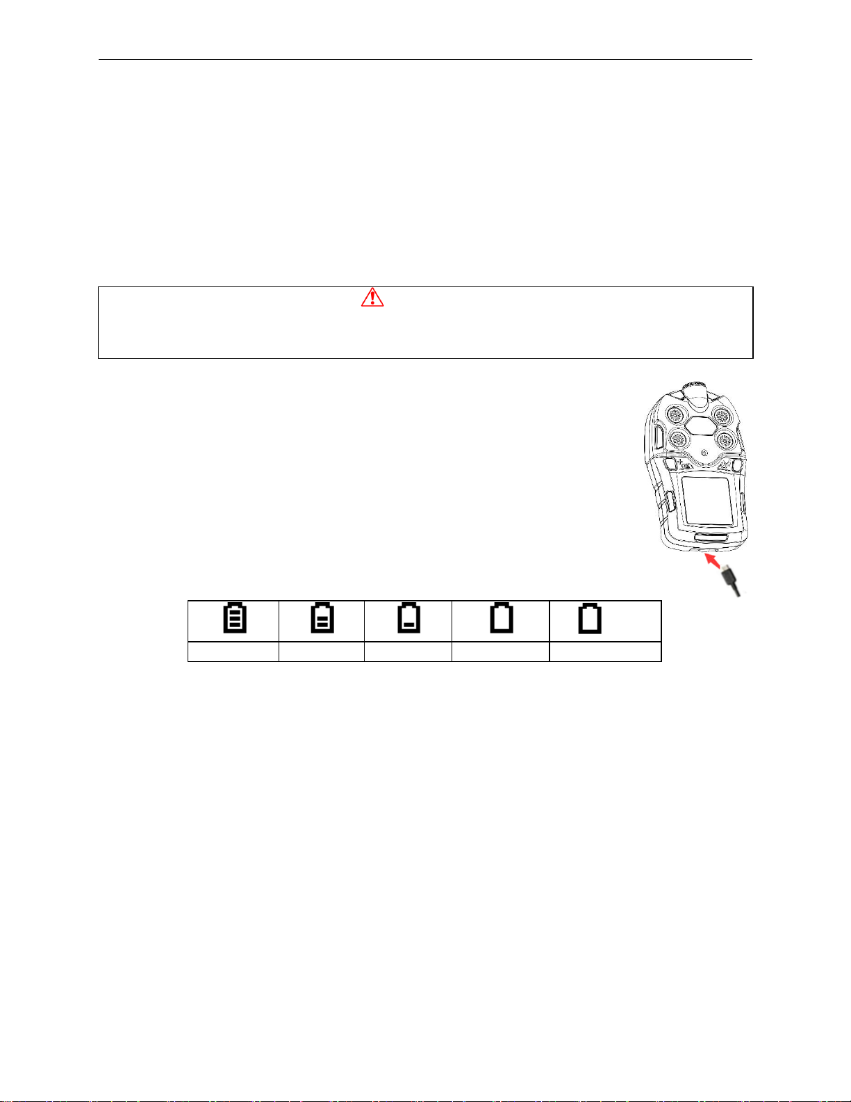
Plug the mini end of the Micro-USB cable into the charging port of POLI, and
the other end to a USB power adaptor or the USB port of a computer. The
screen will display a battery icon from empty to full and one alarm LED will
remain yellow. When the battery is fully charged, the icon displays full grid
status (see Section 3.1), and the alarm LED turns green.
2.2 Battery Status
The battery icon on the display shows how much charge is in the battery, and
alerts of any charging problem.
blink
Full charge
2/3 charge
1/3 charge
Battery Low
Battery Alarm
When the battery’s charge falls below a preset voltage, the instrument warns by beeping once
and flashing once every minute. The instrument automatically powers down within 10 minutes,
after which the battery must be recharged. When a low-battery alarm occurs, we recommended
promptly switching instruments to a fully charged POLI, and/or charging the battery in a nonhazardous location.
2.3 Battery Replacement
The POLI Lithium-ion battery pack is free of maintenance. In case of a battery failure or end of
operating life, please contact the mPower Service Department or an authorized service center for
a battery replacement.
Page 7
POLI User’s Guide
7
3. User Interface
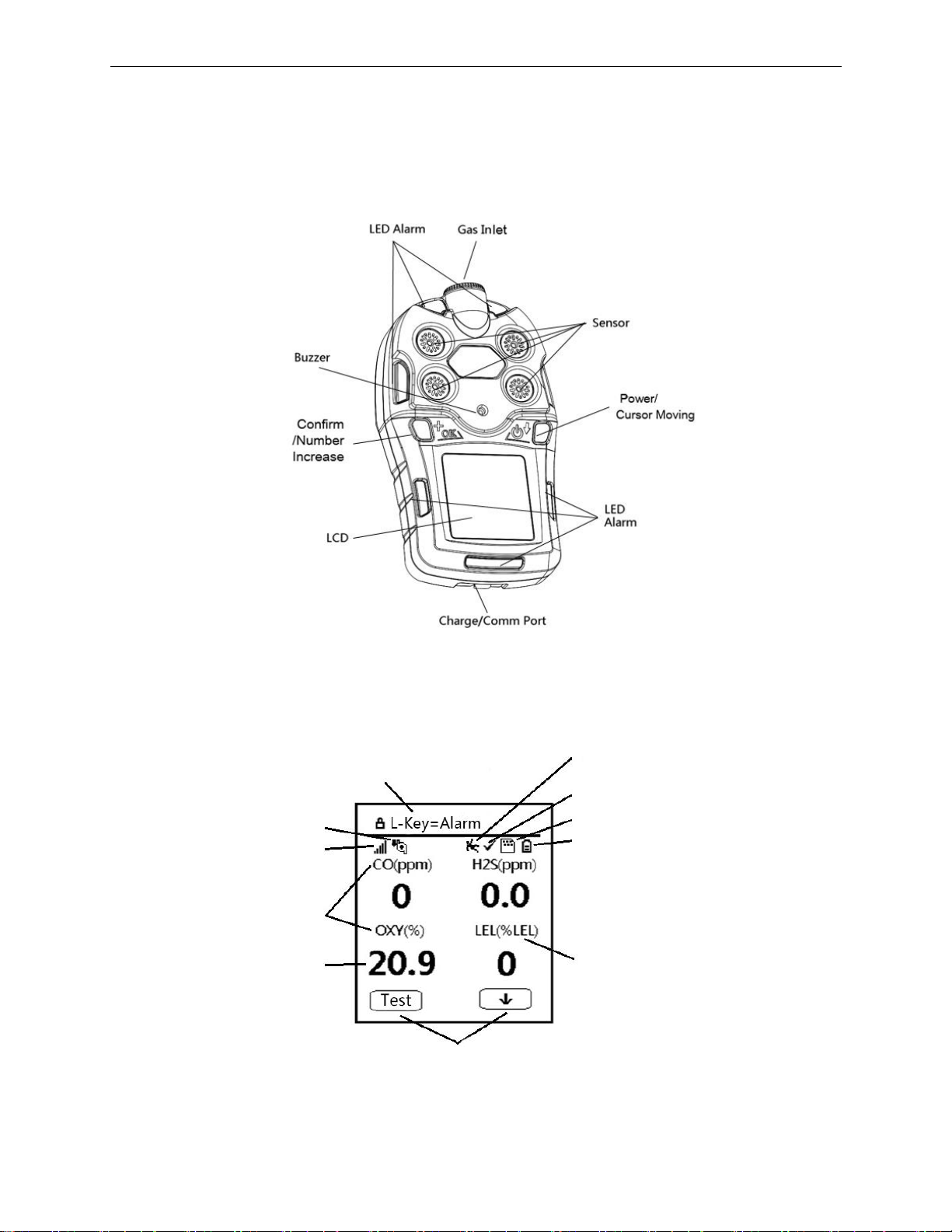
The POLI user interface consists of two keys, four sensor sockets, one large Liquid Crystal
Display (LCD), eight alarm LEDs, one buzzer, and two vibration alarms.
3.1 Displays and Keys
The LCD provides visual information that includes real-time gas readings, sensor types, datalog /
battery / pump / wireless status, and others.
Special notice
Man Down alarm enabled
Datalog on reminder
Battery status
Unit of measure
Functions of left and right keys
Concentration
reading
Sensor type
Wireless status
Pump status
Valid on Cal & Bump
(pump models)
(Gas inlet/outlet
diffusion models)
Page 8
POLI User’s Guide
8
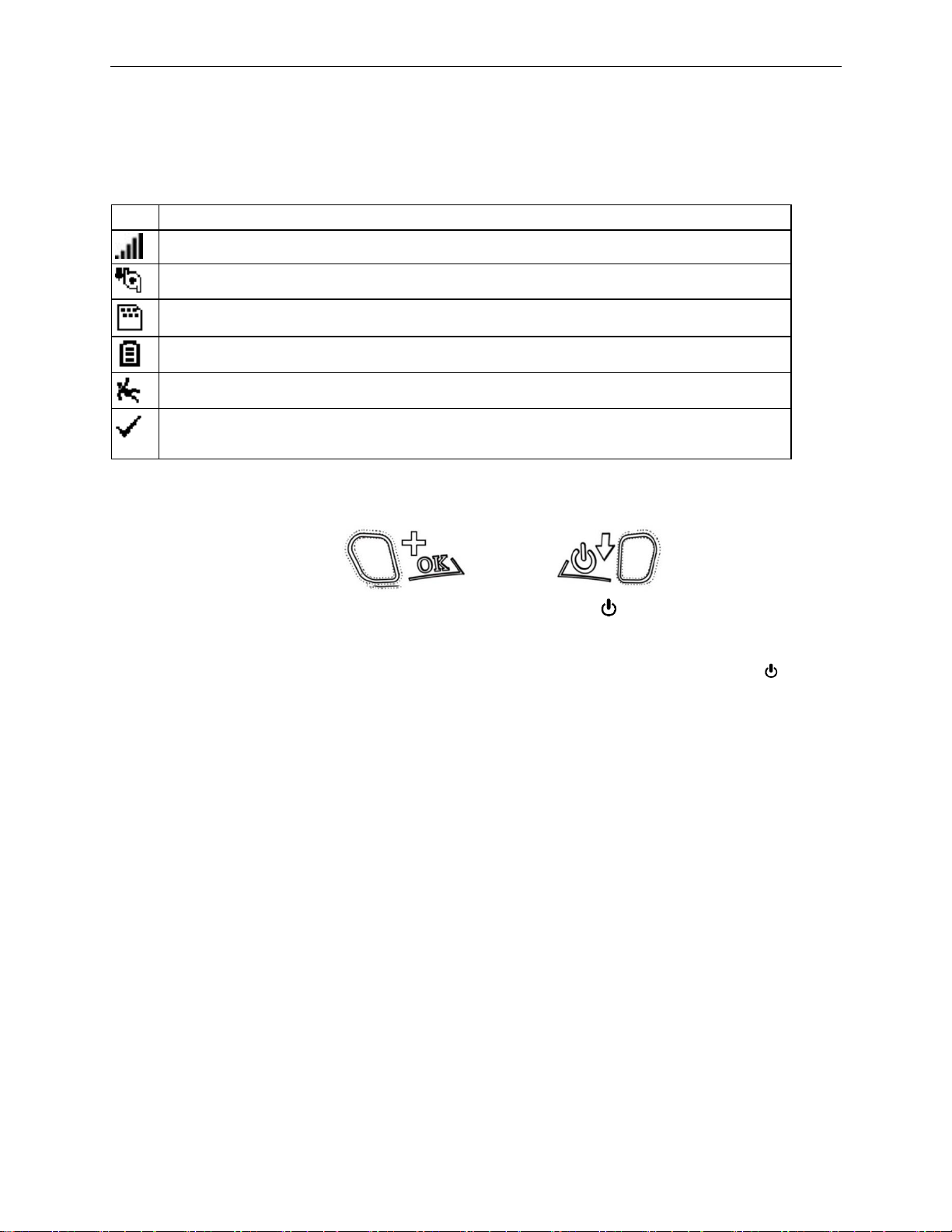
3.1.1 Status Indicator Icons
Along the top of most screens are status icons that indicate whether a function is operating and/or
its strength or level.
Icon
Function
Wireless signal strength at 0-5 level
Pump status (pump versions only)
Datalogging enabled (cannot turn off)
Battery voltage status
Man-down alarm enabled
All sensors have been bump tested and calibrated; no sensor is overdue for a bump
test or calibration according to the intervals configured on the instrument.
3.1.2 Keys and Interface
The POLI has two keys:
Left [+/OK] Key Right [ /↓] Key
Confirm Operation/Increase Number Power On-Off/Move Cursor
These two keys are marked as [+/OK] to Confirm Operations or Increase Number and [ /↓] to
Power On-Off / Move Cursor. They also act as ‘soft keys’ mapped to two text or symbol boxes
at the LCD bottom that change numbers and make selections under various menus.
In addition to the functions described above, the Left [+/OK] key can be used to manually
activate the LCD backligh when it is off, and to manually test the LED, audio and vibration
alarms from the main display.
3.1.3 Alarm Overview
The POLI provides an unmistakable five-way alarm notification that combines local alarms on
the device with real-time remote wireless alarm notification to enhance worker safety up to the
next level. Device alarms include audible buzzer, visible bright LED lights, vibration, and alarm
notification on the display. These can be programmed or selectively turned on or off.
During each measurement period, the gas concentration is compared with the programmed alarm
limits for Low, High, TWA and STEL alarms. If the concentration exceeds (or goes below, in the
case of oxygen) any of the preset limits, the alarms are activated immediately to warn both the
POLI user and a remote safety officer (if wireless is enabled) of the alarm condition.
A major new feature is the Man-Down detection, which can be enabled to activate local and
remote alarms when the user has collapsed or stopped moving. In addition, the POLI alarms
when the battery voltage is low, pump is blocked, and in other fault conditions.
Page 9

POLI User’s Guide
9
4. Basic Operation
4.1 Turning On
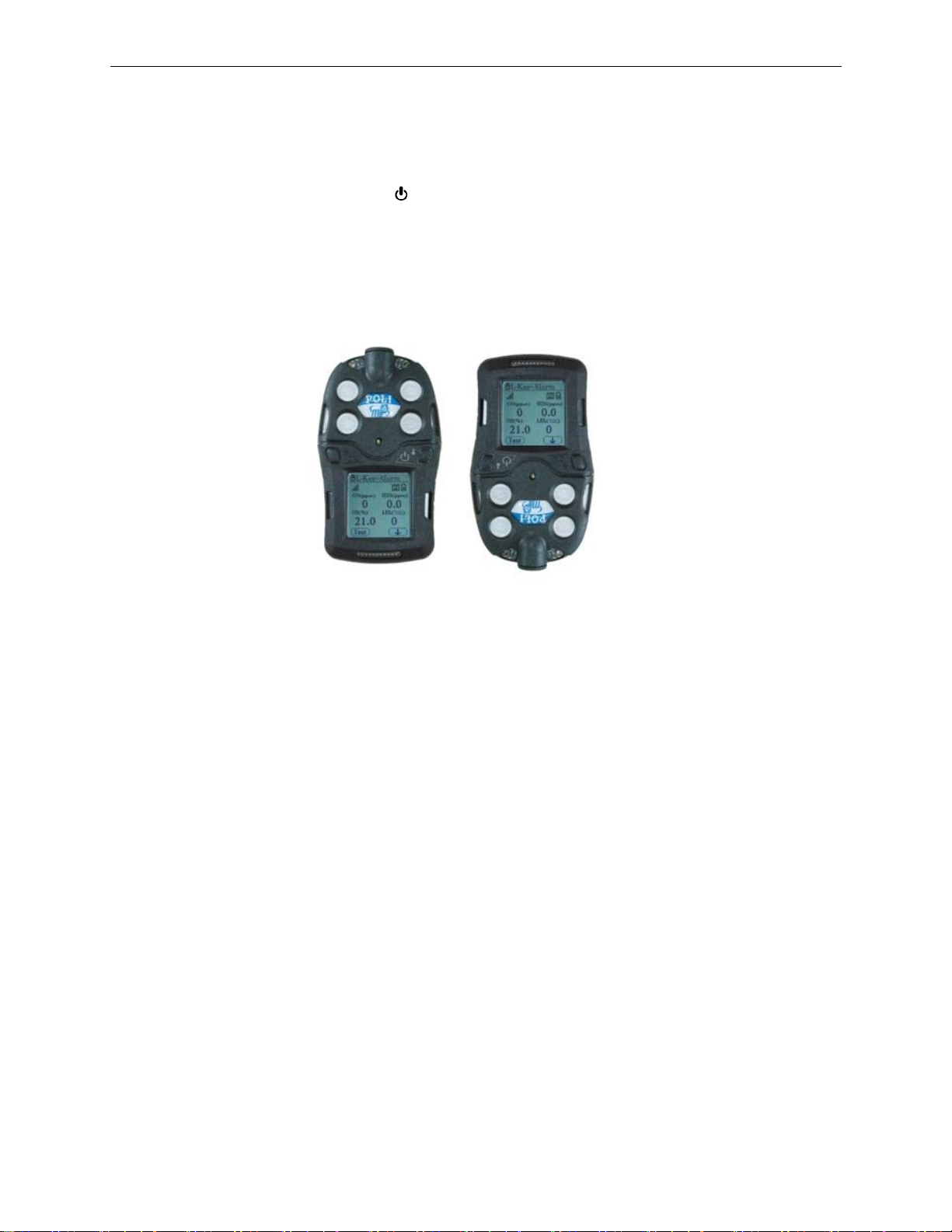
Press and hold the [ /↓] Key for 3 seconds, until the buzzer beeps and the red LED turns on. As
the unit is powers on, it will display information such as:
• mPower logo and Company name
• Product type, Model No. and Serial No.
• Firmware version, Build date and time
• Battery type and Voltage
• Datalog interval
• Alarm Limits for each Sensor type
The POLI’s main reading screen then appears. It usually takes 1 to 2 minutes for sensors to show
meaningful readings. For some sensors not fully warmed up by the time, the main screen shows
‘- -’ instead of numerical values until the sensor is stabilized, typically in a few more minutes. It
then displays instantaneous readings similar to the screens shown in Section 2.2 (depending on
the sensors installed) and is ready for use.
Note: If the battery has insufficient power, the LCD briefly shows the message ‘Battery Fully
Discharged’ and the POLI shuts off automatically. The battery should then be recharged or
replaced with a fully charged battery before turning on again.
IMPORTANT!
If a major error that prevents the POLI from functioning occurs during startup, the message
‘Contact Service’ is displayed. The instrument should be shut off and sent for service.
4.2 Turning Off
In normal reading mode, press and hold the [ /↓] key. The unit will show a 5-second count
down, with red LED flashes and buzzer beeps once per second. After the last long flash and
beep, the unit displays ‘Power Off’, and turns off.
Caution: The alarm is loud. During startup, one can mute most of the sound by temporarily
holding a finger over the buzzer opening hole. Do not put tape over the buzzer opening as it
permanently mutes and causes a serious safety concern.
Page 10
POLI User’s Guide
10
4.3 Active Sensor Displays
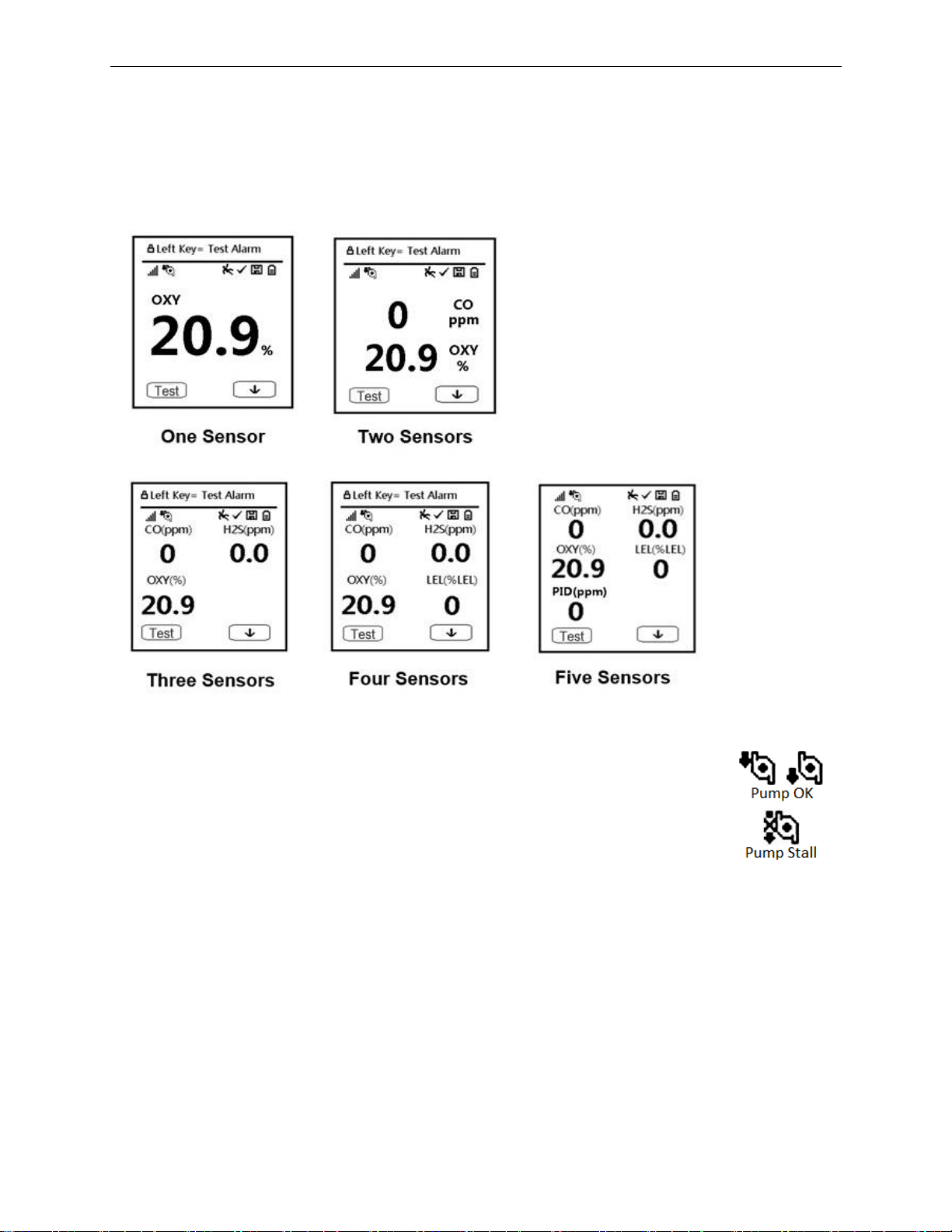
The POLI is a flexible platform with four sensor sockets that allows use of anywhere between
one and five sensors, the latter with a dual toxic sensor. When one or more sensors is either not
installed or turned off, the display only shows the installed, active sensors:
4.4 Pump Status
During normal operation, the pump icon alternately shows inflow and outflow. If
there is a pump failure or obstruction, the alarm sounds and the pump stall icon
blinks on and off. If this occurs, clear the obstruction and press the Left [+/OK]
key to restart the pump.
IMPORTANT!
Obstructions can cause premature wear on the pump and false readings. If the pump does not
restart after pressing [+/OK], consult the Troubleshooting section of this guide or contact an
mPower service center for technical support.
Note: Pump status is not indicated on diffusion versions of the POLI.
Page 11
POLI User’s Guide
11
4.5 Alarm Testing
Under normal operation mode and non-alarm conditions, the audible (buzzer) alarm, vibration
alarm, LED, and backlight can be tested at any time by pressing [+/OK] once.
WARNING!
If any of the alarms do not respond to this test, check the Alarm Settings in Configuration Mode
to see if the alarms have been turned off. If any of the alarms is enabled but not functional, do
not use the instrument. Contact an mPower service center for technical support.
4.6 Main User Menu
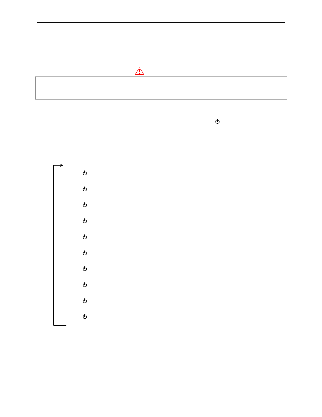
The user menu in the reading mode is simple to go through using the [ /↓] and [+/OK] keys.
The information sequence is shown below. The Peak, Minimum, STEL and TWA for each
sensor since turn-on are displayed, with the option to clear and re-start Peak or Minimum. In
addition, If the POLI is fitted with a PID or Pellistor LEL sensor, the corresponding Calibration
Gas and Measurement Gas (and its Correction Factor) are displayed (after Battery information).
REAL-TIME READINGS
[ /↓]
PEAK ----- Clear Peak? [+/OK]
[ /↓]
MINIMUM ----- Clear Min? [+/OK]
[ /↓]
STEL
[ /↓]
TWA
[ /↓]
DATE, TIME, TEMPERATURE
[ /↓]
BATTERY TYPE, VOLTAGE, RUN TIME, LAST RUN
[ /↓]
PID CAL GAS, MEASUREMENT GAS, CORRECTION FACTOR (If installed)
[ /↓]
LEL CAL GAS, MEASUREMENT GAS, CORRECTION FACTOR (If installed)
[ /↓]
START COMM?
[ /↓]
REAL-TIME READINGS
The last display before returning to Real time readings is “Start Comm?”. Pressing the check box
stops the pump and readings, and waits for communication with a PC using mPower Suite to
transfer data or update the instrument configuration (see Section 6).
Page 12
POLI User’s Guide
12
5. Configuration Mode
The Configuration Mode (Config Mode) is used to adjust the POLI’s operation settings and
calibrate sensors. Remember that the two text/symbol boxes at the bottom of the display are
mapped to the Left [+/OK] and Right [ /↓] keys and will vary with the menu.
5.1 Entering Configuration Mode
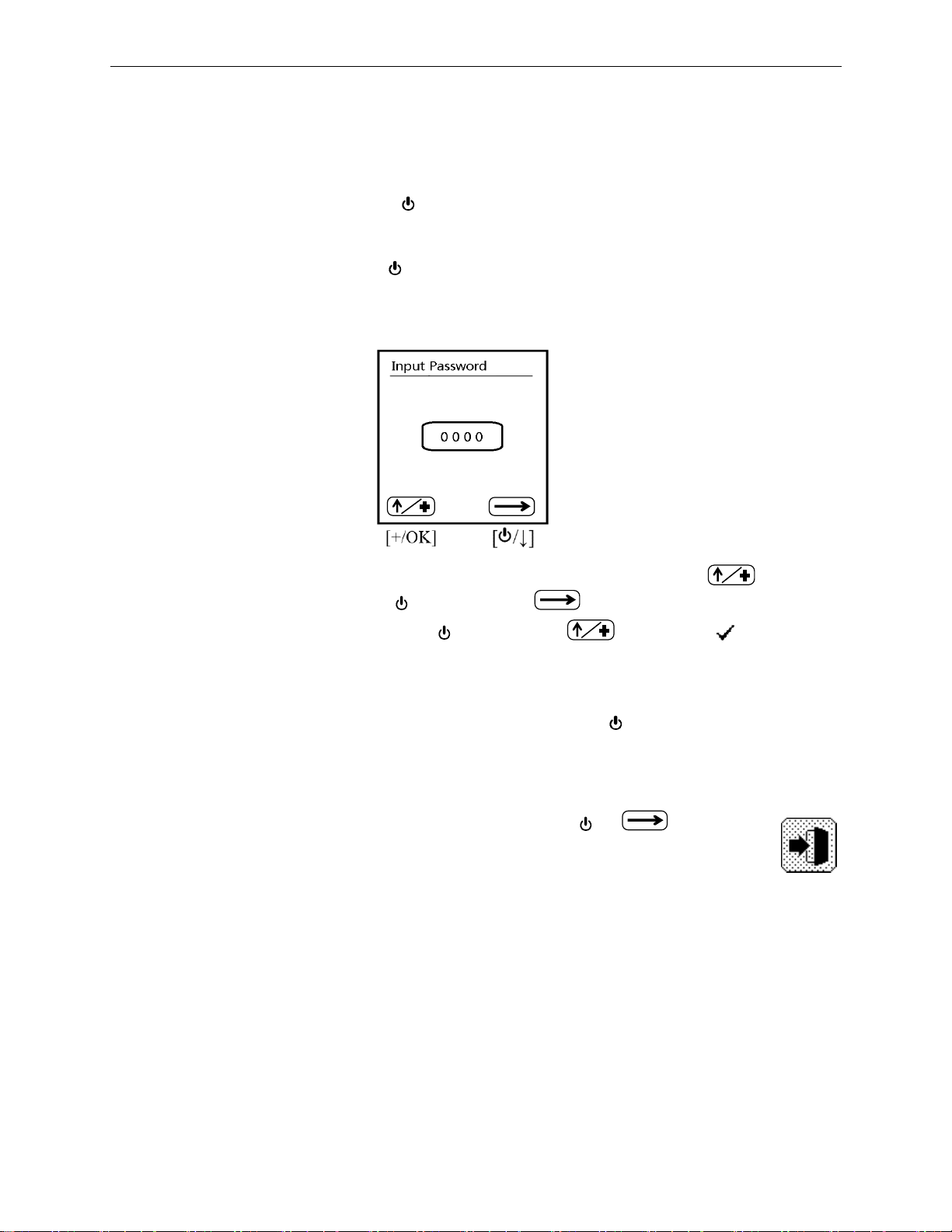
Press and hold both the [+/OK] and [ /↓] keys simultaneously for 3 seconds until the password
screen appears. The default password is ‘0000’ and can only be changed using mPower Suite
software. The password is needed only the first time Config Mode is entered after power is
turned on.
•
Increase the number from 0 through 9 by pressing [+/OK] (mapped to ).
•
Step from digit to digit using [ /↓] (mapped to ).
•
After entering all four digits, Press [ /↓] again and changes to ‘ ’.
•
Press [+/OK] to register the password and enter Config Mode.
If the password is not correct, the message ‘Incorrect!’ is displayed and the unit returns to the
reading mode automatically. If a wrong digit is entered, use the [ /↓] key to move the cursor
among four digits and press [+/OK] to change the input.
5.2 Exiting Configuration Mode
To exit, scroll through the main Confg Mode Menu using the [ /↓] key until the
door symbol is highlighted and press [+/OK]. Or simply wait, and the unit will return to
normal operating mode automatically if no buttons are pressed for one minute.
Page 13
POLI User’s Guide
13
5.3 Navigating Configuration Mode to Edit Parameters
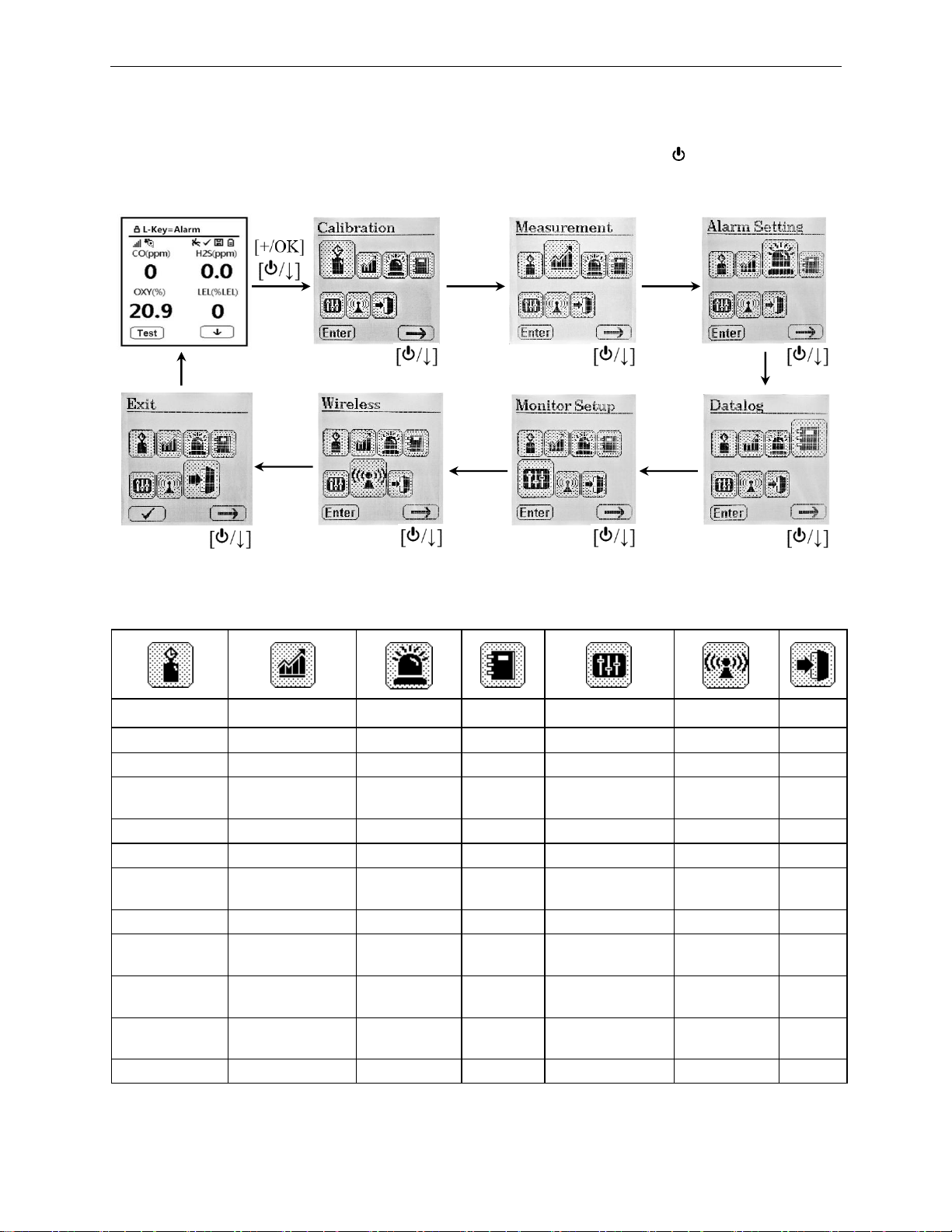
After entering Config Mode, the calibration menu is displayed first. Press [ /↓] (→) to step
through the menus and [+/OK] (Enter) to enter a menu to edit the parameters in its submenu.
5.3.1 Menus and Sub-menus
Configuration Mode menus and sub-menus are organized as shown here:
Calibration
Measurement
Alarm
Datalog
Monitor Setup
Wireless**
Exit
Fresh Air Calib
Enable/Disable
High Limit
Clear All
LCD Contrast
Register
Nitrogen Calib
Gas Unit
Low Limit
Interval
Pump Speed*
Host ID
Span Calib
Exit
STEL Limit
Sensor
Select
Pump Stall*
Channel
Bump Test
TWA Limit
Exit
TemperatureUnit
Exit
Span Value
Alarm Device
Language
Exit Heart Beat
Light
Back Light Mode
M-D† On/Off
LCD Auto Flip
Man-Down
Warn Time
Clock Set-up
Man-Down
Threshhold
Exit
Man-Down
Tmotionless
Exit
* Operational in Pump versions only. ** Operational in Wireless versions only. † M-D = Man-Down
Page 14
POLI User’s Guide
14
5.3.2 Navigating Lists
There are two types of menus in Configuration Mode: 1) those that ask for selection from a list
and 2) those that ask for a numerical value to be entered. Simple lists and those with radio
buttons are used when only one option can be selected. Check [X] boxes are used when multiple
options can be selected at the same time.
5.3.2.1 Simple Lists
When a simple list is shown, use the [ /↓] down-arrow key to highlight the desired item and
then press [+/OK] (Enter) to enter the sub-menu. To exit the simple list, scroll down until Exit is
highlighted and the Enter key changes to ‘ ’, then press [+/OK].
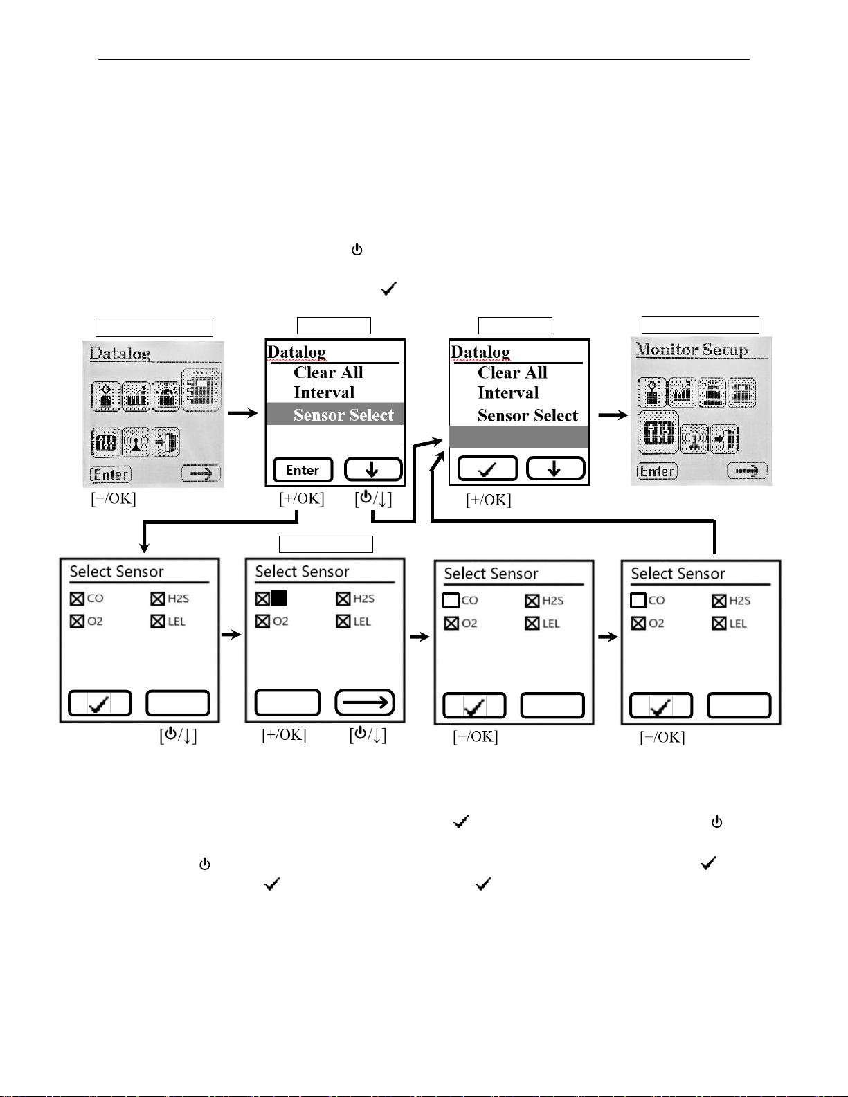
5.3.2.2 Check [X] Box Lists
When a Check [X] Box list appears as shown above, follow the numbered sequence in blue
above. If no change is desired, simply press [+/OK] ‘ ’ to exit. To make changes, 1 press [ /↓]
and the first item is highlighted. 2 Use [+/OK] to toggle the item checked or unchecked, and 3
use the arrow [ /↓] to move to the next item or end of the list where (Toggle) changes to ‘ ’.
Finally, 5 press [+/OK] ‘ ’ to exit and 6 press [+/OK] ‘ ’ again to save. If Save is not
acknowledged, no changes will be made and the unit will revert back to the previous settings.
Main Config Menu
Simple List
Main Config Menu
Simple List
Check-Box List
Change
Change
Toggle
CO
2 1 3
4
5
Change
Save?
Exit
Exit
Page 15
POLI User’s Guide
15
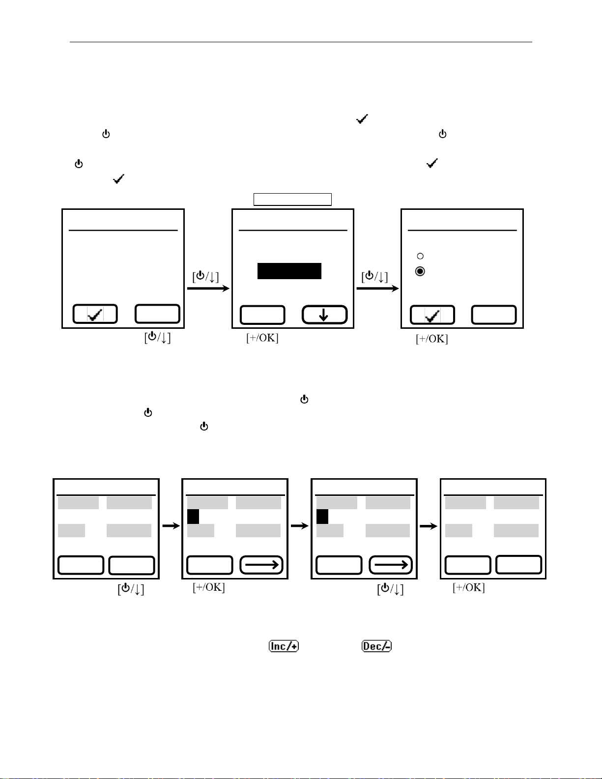
5.3.2.3 Radio Button Lists
Radio buttons are used when only a single item in the list can be selected, and there are no
further sub-menus. When a radio button list appears, follow the numbered sequence in blue as
shown below. If no change is desired, simply press [+/OK] ‘ ’ to exit. To make changes, 1
press [ /↓] (Change) and the first item is highlighted. 2 Use the down arrow [ /↓] to move to
the desired item, 3 use [+/OK] (Select) to choose the highlighted item, and 4 use the down arrow
[ /↓] to move to the next item or end of the list where (Select) changes to ‘ ’. Finally, 5 press
[+/OK] ‘ ’ to exit.
5.3.3 Entering Numerical Values
To enter numerical values in a list, proceed as shown below. If no change is desired, simply press
[+/OK] (Done) to exit. To make changes, press [ /↓] (Change) and the first item is highlighted.
Use the arrow [ /↓] to move to the desired item(s), use [+/OK] (Inc/+) to increase the numerical
value. Then use the arrow [ /↓] to move to the next item or end of the list where (Inc/+) changes
to (Done). Finally, press [+/OK] (Done) to exit and press [+/OK] (Done) again to save. If Save is
not acknowledged, no changes will be made and the unit will revert back to the previous settings
5.3.3.1 Decreasing Numerical Values
To switch the Left soft key function from increasing to decreasing, hold both keys down
simultaneously for about 2 seconds until changes to . After exiting the menu, the
Left key will automatically revert to increasing numbers again.
M-D On/Off
○ Off
◉ On
○ Vertical Off
○ Horizontal Off
M-D On/Off
○ Off
◉ On
○
Vertical Off
○ Horizontal Off
Select
M-D On/Off
○ Off
◉ On
○ Vertical Off
○ Horizontal Off
Change
4
2
Change
1
3
5
Radio Button List
Low Limit
CO(ppm) H2S(ppm)
35 10.0
O2(%) LEL(%LEL)
19.5 10
Low Limit
CO(ppm) H2S(ppm)
35 10.0
O2(%) LEL(%LEL)
19.5 10
Done
Inc/+
Low Limit
CO(ppm) H2S(ppm)
50 10.0
O2(%) LEL(%LEL)
19.5 10
Low Limit
CO(ppm) H2S(ppm)
50 10.0
O2(%) LEL(%LEL)
19.5 10
Inc/+
Done
Change
Change
Page 16

POLI User’s Guide
16
5.4 Calibration and Bump Testing
Use this menu to perform zero or span calibration for one or more sensors, bump test the sensors
and alarms for function, and change the span gas concentration.
The POLI should be calibrated on the first day of use and at regular intervals not to exceed 180
days, depending on use and exposure to particulates, contaminants and sensor poisons. A daily
bump test should be performed to ensure a functional response of all sensors and alarms.
• BUMP TEST is defined as a brief exposure to sensor gases, typically 30 seconds, just long
enough to indicate that the sensors are responsive and the alarms are functional, without
concern for a quantitative measurement.
• CALIBRATION is defined as exposing the sensor(s) to a known concentration standard gas
for the full calibration time (typically 60 to 90 seconds) and setting the reading of the
sensor(s) equal to the concentration of the calibration gas.
Calibration intervals and bump test procedures may vary due to sensor type, ambient conditions,
local regulations and/or the user’s company policies.* Automatic reminders for calibration and
bump tests can be set up using the mPower Suite software (see Section 6.1). When a calibration
or bump is due, the sensor name alternates with a highlighted 'CAL' or ‘BUMP’ as shown below:
Calibration is also required if:
• The sensor module has been replaced with one whose calibration is overdue.
• The user has changed the calibration gas type without recalibrating the instrument.
• The sensor has failed in a previous calibration.
For more on calibration frequency see Tech/App Note 3 “How Often to Calibrate Gas Detectors”.*
* The calibration frequency must be defined by the user’s company policy because each application is different and
may cause a sensor’s sensitivity loss for various reasons out of mPower’s control, such as liquids, dirt or corrosion
preventing gas from reaching a sensor, or exposure to chemicals that poison a sensor’s function. Exotic gas
sensors tend to need more frequent calibration than common O2, LEL, CO and H2S sensors. In general we
recommend a bump test before each day’s use to test sensor response and alarm function. A calibration check can
be performed by applying a known concentration gas to see if the sensors still respond within typical limits. Cal
check intervals can be increased as the user gains experience in the application. If a bump or cal check fails, the
instrument should be given a full calibration. We recommend no more than one month between full calibrations,
but this can be extended for up to 6 months if company policy allows.
Page 17

POLI User’s Guide
17
5.4.1 Calibration Set-Up
5.4.1.1 Span Gas Selection
The gas concentration chosen for span calibration and bump testing should be near the middle to
upper range of the concentrations expected to be measured. If the possible gas concentrations
are unknown, choose a gas concentration near the upper end of the sensor’s range, or near the
highest exposure limit (e.g., TWA, STEL or Ceiling) of concern. Standard 4-gas mixtures allow
calibration of 4 sensors at the same time. mPower has selected a mixture of 50 ppm CO/15 ppm
H2S/2.5% CH4/18% O2, (balance N2) as the recommended calibration gas for such monitors.
Span gas recommendations for other gases are listed at the end of this manual and in TA Note 4.
Some sensors can be calibrated with surrogate gases when the gas they are designed to measure
is highly reactive, expensive or otherwise difficult to obtain.
Note that some common sensor combinations use calibration gases that are incompatible and
therefore must be applied separately, for example chlorine (Cl2) & ammonia (NH3) and chlorine
dioxide (ClO2) and hydrogen sulfide (H2S). For such cases it is important to allow a few minutes
between calibrations to allow one interfering gas to clear out before the other is applied.
5.4.1.2 Calibration Compounds for PID and LEL Sensors
Because PIDs and LEL sensors are broadband detectors, they can be calibrated with many
possible gases. The type of calibration gas is selected from a list of several hundred compounds
in mPower Suite (Section 6.1), typically isobutylene for PID and methane for LEL. The
measurement gas is also selected in mPower Suite. Correction factors are calculated and
automatically applied to make the display read in equivalents of the Measurement Gas.
5.4.1.3 Gas Connections and Regulators
Calibration gas is most easily supplied from a pressurized cylinder controlled by a regulator.
•
Fixed-flow Regulators are pre-set to deliver a consistent flow rate regardless of the gas
pressure remaining in the cylinder. We recommend 0.3 LPM regulators for diffusion POLI
versions and 0.5 LPM regulators for pumped POLI versions.
•
Demand-flow Regulators are more expensive but save gas by allowing only the amount of
gas to flow that the POLI pump withdraws. These regulators cannot be used with diffusion
instruments since they have no pump.
•
Gas Generators provide their own flow and are required for a few gases like ozone (O3)
and chlorine dioxide (ClO2) that are too unstable to be stored in a cylinder.
•
Trigger Regulators supply a puff of gas at an undefined flow and are useful for quickly
doing a functional bump test without entering Config Mode to record the test.
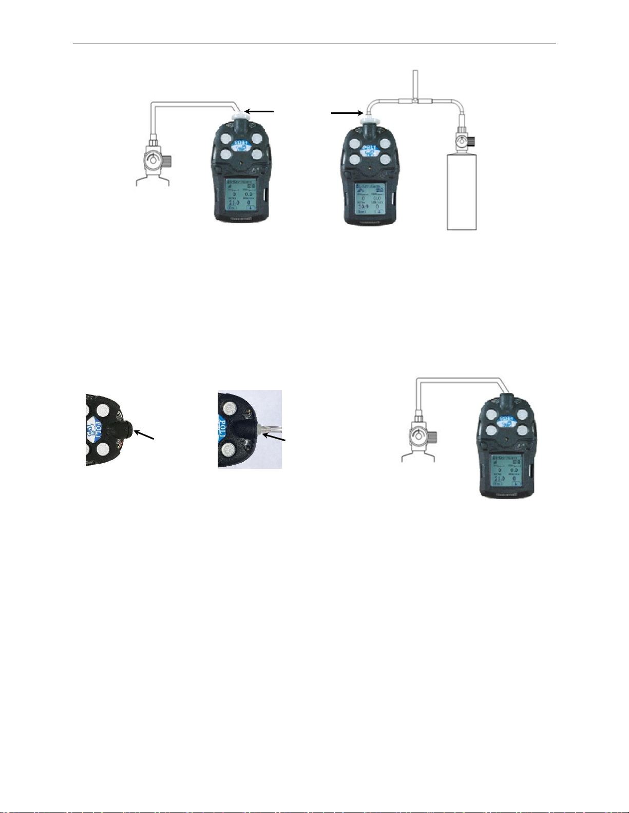
Pumped Instruments. We recommend calibrating the POLI with the pump on the High Flow
setting, where it typically draws between 350 cc/min (0.35 LPM) and 450 cc/min (0.45 LPM)
with a 0.45 µm filter in place. In this case the instrument can be connected directly to the gas
cylinder fitted with either a demand-flow regulator or a 0.5 LPM fixed flow regulator. If the
fixed-flow regulator supplies more than 0.5 LPM, a T-connector, as illustrated below, must be
used in the gas supply line to allow excess gas to escape without being forced through the POLI
pump and sensor chambers. Even when using a T-connector, we recommend no more than 1.0
LPM total flow.
Note: Make sure the pressure in the gas cylinder is >100 psi when using a T-connector.
Page 18
POLI User’s Guide
18
Diffusion Instruments. Diffusion instruments have a black cap covering the Luer connector to
protect the unit from dirt and moisture. This cap must be removed to attach the Luer fitting and
connected tubing leading to the gas supply. (Internal channels distribute the gas to each sensor,
even though during measurements the gas enters and leaves through the four filters on the face of
the POLI.) The gas flow should be low, between 0.2 and 0.3 LPM to avoid pressure build-up in
the sensor channels. Do not use a
5.4.1.4 PTFE Connecting Tubing for Reactive Gases
For reactive gases including ozone, chlorine, chlorine dioxide, hydrochloric acid, hydrofluoric
acid, and absorbable gases such as most VOCs, it is critical to use inert connecting tubing such
as PTFE (Teflon) and make connections as short as practical. More flexible variants such as
PTFE-lined Norprene or PTFE-lined Tygon are suitable alternatives. For most other gases,
including standard 4-gas mixes with carbon monoxide, hydrogen sulfide and methane, Tygon
tubing is adequate and convenient because of its flexibility.
5.4.1.5 Other Attachments
It is always most accurate to calibrate the POLI with all attachments in place in the same manner
as in the field measurements. For example, normally a filter should be used on the POLI inlet for
both measurements and calibration. However, if a filter is not used during measurement (as
preferred in a few cases of highly reactive gases) then no filter should be used during calibration.
Similarly, if extension tubing is being used during sampling, a more accurate calibration is
obtained if the tubing is also attached during calibration. This method accounts for any small
changes made to the gas concentration by the attachment(s).
Demand-flow or 0.5 LPM
fixed flow regulator
Fixed-flow regulator with >0.5 to
1.0 LPM flow using T-connector
Connect
tubing using
Luer fitting
Remove cap
Pumped Instruments
Diffusion Instrument
Connect to gas with
fixed-flow regulator of
0.2-0.3 LPM flow
Luer fitting
Page 19
POLI User’s Guide
19
5.4.2 Fresh Air (Zero) Calibration
Zero calibration should precede span calibration and be done in clean air with 20.9% oxygen.
This procedure determines the zero points of most sensors and the span calibration for the
oxygen sensor. No gas connections are required if the ambient air contains no detectable
contaminants.
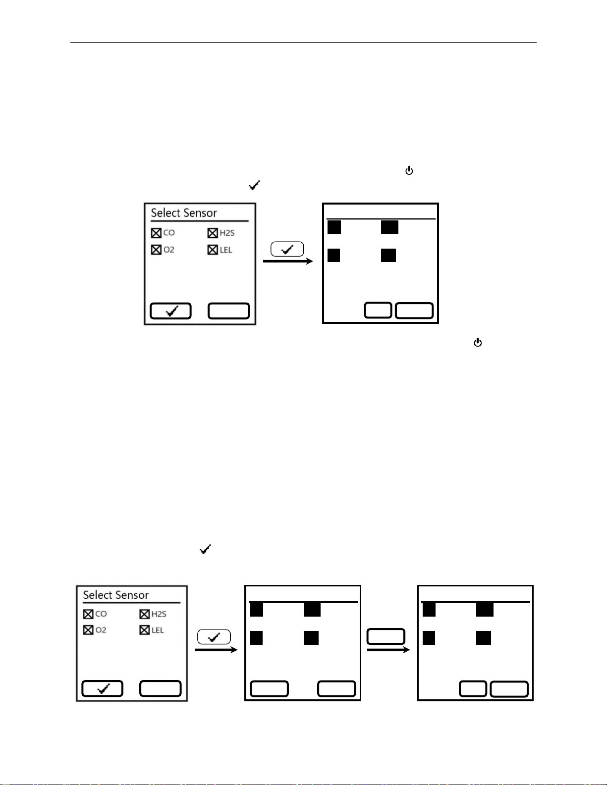
In Configuration Mode, enter the Calibration menu and select ‘Fresh Air Calib’ to show the
selected sensor list. De-select any sensor(s) not wanted to be zeroed ([ /↓] (Change)). Start the
zero calibration by pressing [+/OK] ‘ ’ to initiate the 30-second zero calibration count-down.
The zeroing process can be aborted at any time during this count-down by pressing [ /↓]. When
the zero calibration is complete, the ‘Pass’ or ‘Fail’ result is shown for each sensor.
5.4.3 Nitrogen Calibration
Nitrogen calibration is used to set the baseline for the oxygen sensor only. This calibration is
needed only for applications in rather low oxygen concentrations below about 5 Vol%, because
the oxygen baseline is usually quite stable. It is not normally needed for breathing air
applications near 20.9 Vol% oxygen.
To perform an oxygen zero calibration, enter the ‘Nitrogen Calib’ menu, apply nitrogen gas to
the POLI inlet, and proceed as described for Fresh Air Calibration above. The nitrogen countdown time is 60 seconds. Other inert gases such as argon or helium could also be used.
5.4.4 Span Calibration
In Configuration Mode, enter the Calibration menu and select ‘Span Calib’. Depending on the
configuration of the POLI, multiple sensors may be calibrated simultaneously. Select the desired
sensors and press [+/OK] ‘ ’. Verify that the span gas concentrations match those of the gas
cylinder. If not, abort and go to the Span Value menu to adjust. If OK, turn on the gas flow,
Fresh Air Calib
CO
H2S
----
----
O2
LEL
---- ----
Abort
29
Change
Change
Span Calib
CO H2S
50 ppm 15 ppm
O2 LEL
18% 50 %LEL
Abort
Span Calib
CO H2S
---- ----
O2 LEL
---- ----
Abort
59
Start
Start
Page 20
POLI User’s Guide
20
connect the gas to the POLI, and press Start to initiate the 60-second count-down. The When
complete, the display shows the sensor readings alternately with a ‘Pass’ or ‘Fail’ message. The
span calibration can be aborted at any time during the count-down by pressing [ /↓] (Abort).
NOTE: If the sensor calibration fails, try again. If calibration fails again, turn off the power and
replace the sensor. WARNING! Do not replace sensors in hazardous locations!
Gases that are not available as mixtures must calibrated individually by de-selecting all other
sensors. When calibrating sensors for cross-reactive gases such as chlorine and ammonia or
chlorine dioxide and hydrogen sulfide, be sure to allow a few minutes between calibrations for
the previous gas to clear and toxic gas sensor readings to return to zero.
5.4.5 Bump Test
Enter the Calibration menu and select ‘Bump Calib’. Most commonly the same gas is used for
bump testing as for a full calibration. Perform the bump test in the same manner as for Span
Calibration, ensuring that the test gas concentration values match those of the gas supply
cylinder. The Bump Test lasts 30 seconds, or as long as it takes to pass, whichever is shorter. It
can be aborted at any time during the 30 seconds. When the bump test is complete, the ‘Pass’ or
‘Fail’ result is shown for each sensor. Be sure to calibrate any sensor that fails a bump test.
Important! Make sure all of the sensors have warmed up before performing the bump test. The
instrument will display three dashes (‘--’) next to the sensor name during warm up. Once a
sensor has warmed up it will show a concentration reading and a bump test can proceed.
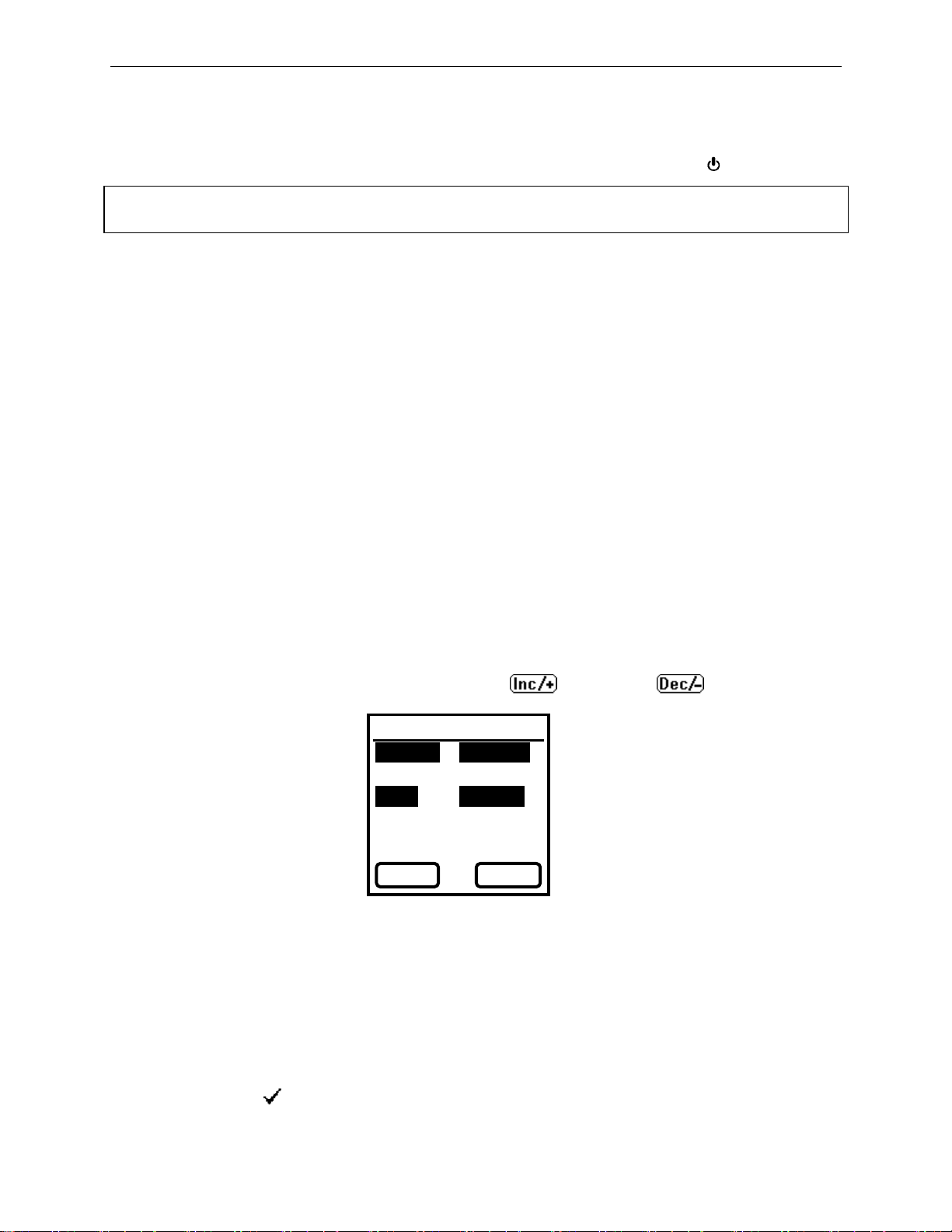
5.4.6 Set Span Value
To change the calibration gas concentrations, enter the Calibration menu and select ‘Span
Value’. Update the values as need and press Done to exit and acknowledge any changes when
asked to ‘Save?’ To switch the Left soft key function from increasing to decreasing, hold both
keys down simultaneously for about 2 seconds until changes to .
5.5 Measurement
Use this menu to enable or disable sensors and to set gas concentration units. Note that the
Measurement Gas type for PID and LEL sensors can only be selected using mPower Suite.
5.5.1 Enable/Disable Sensor
Sensors can be disabled if they are not needed for a particular application, or if a sensor fails but
the other sensors still provide useful readings. In Config Mode, enter the Measurement menu and
select ‘Enable/Disable’. Press ‘Change’ and select or de-select sensors as needed. Then scroll
to and press on the ‘ ’ box. Acknowledge ‘Save’ for any changes made, or press X to discard.
Span Value
CO(ppm)m H2S(ppm)
50 15
O2(%) LEL(%LEL)
18.0 50
Change
Done
Page 21
POLI User’s Guide
21
5.5.2 Gas Unit
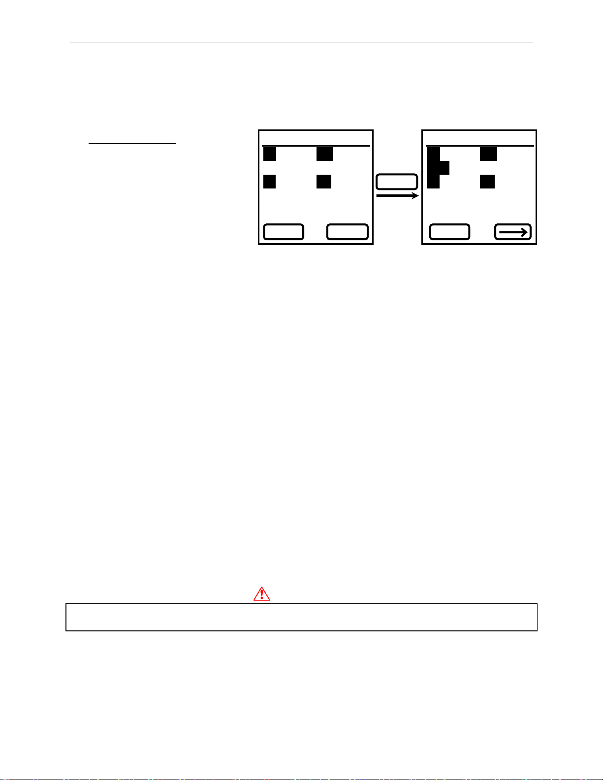
From the Measurement menu select ‘Gas Unit’ and press ‘Change’ to alter the concentration unit
for any sensor. Then scroll to and press ‘Done” and ‘Save’ to save changes. Options include:
Gas Unit Options
ppm (parts per million)
mg/m3 (mg per cubic meter)
µmol/mol (micromole per mole )
10-6 (1 millionth mole fraction)
% (Volume %)
% LEL (% of Lower Explosive Limit
The units ppm, µmol/mol (micromole per mole) and 10-6 are essentially the same unit expressed
with a different label. Conversion from ppm to mg/m3 is done automatically using the gas
molecular weight stored in the firmware. Units for sensors reading in % Vol or %LEL cannot be
changed.
CAUTION! Be sure that the Gas Concentration Unit of the instrument matches that of the
Calibration Gas used for each sensor. Otherwise dangerously low readings could result. Once
calibration is complete, the units can be changed between the first four on the list above and the
readings will be correct. Then make sure that alarm limits are entered in the same units that are
selected for the concentration readout.
5.6 Alarm Settings
Use this menu to change alarm limits, select alarm devices, enable a heartbeat light and enter
Man-down alarm parameters.
5.6.1 High, Low, STEL and TWA Alarm Limits
In the ‘Alarm Setting’ menu, select the desired alarm type and enter the values for each sensor as
described above in Section 5.3.3. Make sure that the concentration units of the alarm limits
match those selected for the displayed concentration readings. Note: Some alarm limits are not
applicable to all sensors. For example, the oxygen and LEL sensors do not appear in the list of
STEL and TWA alarm limits.
5.6.2 Alarm Device
Use this menu to select or de-select any combination of the audio (buzzer), visual (LED) or
vibration alarms.
WARNING!
Disabling all of the alarm devices prevents notification of hazardous gas concentrations and can
lead to serious injury or death!
5.6.3 Heart Beat Light
The ‘Heartbeat’ light flashes an LED at regular intervals to verify that the unit is still on. This is
especially useful in high noise situations where the pump cannot be heard. The interval between
flashing lights can be set between 1 and 10 seconds, or turned off by setting to 0.
Gas Unit
COm H2S
ppm ppm
O2 LEL
% %LEL
Change
Done
Inc/+
Change
Gas Unit
COm H2S
ppm ppm
O2 LEL
% %LEL
Page 22
POLI User’s Guide
22
5.6.4 Man-Down Function
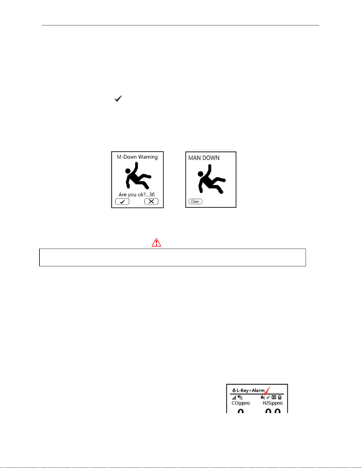
The POLI includes a Man-Down Alarm as a critical and potentially lifesaving safety feature for
all models. When a user who is carrying the instrument stops moving or shifts to an abnormal
position for a set period of time, the Man-Down Alarm is triggered, notifying anyone within
earshot that the user may need rescue. The user is pre-warned by visual and audio alarms at 2
pulses per second that the Man-Down condition has been detected. He then has a set time to clear
the warning by pressing ‘ ’ if he is OK. If not cleared in time, a louder Man-Down Alarm
starts, consisting of a short vibration followed by a pitch-rising, once-per-second alarm to warn
nearby co-workers. During the warning period the user can also press ‘X’ if he is in distress, to
start the full Man-Down Alarm immediately. These alarms are very different from high-gas
alarms, so that co-workers can easily distinguish them. If a full Man-Down Alarm starts but the
user is OK, it can be stopped using the Left key (Clear).
Future versions of the POLI will allow connection to a wireless network for transmission of
various alarms, including Man-Down, to team-mates, supervisors or safety officers on site or at
remote locations for timely rescues.
WARNING!
The Man-Down feature cannot detect a worker in distress in all situations even if they have
collapsed. The Man-Down function should not be used to supplant other safety precautions.
5.6.4.1 Man-Down On/Off
The Man-Down On/Off function has 4 settings:
•
Off
•
On Alarm is triggered with insufficient movement in any direction. The pre-warn or
alarm can be cleared by quickly tilting, or by pressing the Left [+/OK] key.
•
Vertical Off The alarm stays off as long as the instrument is held in a vertical position,
such as clipped to a belt (or straight upside-down), and triggers when in any other
position including held sideways or laying face up or down. A pre-warn can be cleared by
quickly returning the POLI to a vertical position, or pressing the Left [+/OK] key.
•
Horizontal Off The alarm stays off as long as the instrument is held in a horizontal
position, such as laying face up on a table, and triggers when in any other position. A prewarn can be cleared by quickly returning the POLI to a horizontal position, or pressing
the Left [+/OK] key.
The Man-Down icon on the main screen verifies that the
Man-Down function is enabled.
Page 23

POLI User’s Guide
23
5.6.4.2 Man-Down Warn Time
This menu allows adjustment of the time allowed for the user to clear a pre-warn signal before
the unit goes into full Man-Down Alarm. The pre-warn time can be adjusted between 10 and 60
seconds and the default value is 30 seconds.
5.6.4.3 Man-Down Threshold (Sensitivity)
This menu allows adjustment of the sensitivity to motion (On Mode) or position changes
(Vertical or Horizontal Off Modes) for detecting a Man-Down condition. Low sensitivity
means fewer alarms and High sensitivity means a greater likelihood of triggering an alarm.
5.6.4.4 Man-Down Motionless Time
This menu allows adjustment of the time allowed for stopped motion (On Mode) or position
changes (Vertical or Horizontal Off Modes), before a Man-Down condition is detected. The
motionless or position-change time can be adjusted between 10 and 60 seconds and the default
value is 30 seconds.
5.7 Datalog
The instrument displays a floppy disk icon on the main screen to indicate that gas readings are
being recorded in datalog. The instrument stores the measured gas concentration for each sensor
along with date and time for each measurement. The POLI has enough memory to record six
months’ worth of data for four sensors at one-minute intervals. All data are retained (even after
the unit is turned off) in non-volatile memory so that they can be downloaded at a later time to a
PC using mPower Suite software (see Section 6). Datalogging cannot be turned off. When
datalogging is full, it begins to overwrite the oldest data, which are permanently lost.
5.7.1 Clear All Data
This operation erases all data stored in the Datalog.
CAUTION!: Once the Datalog is cleared it cannot be recovered.
5.7.2 Datalog Interval
The default interval is 60 seconds, and can be changed in a range of 1 to 3,600 seconds.
5.7.3 Datalog Sensor Selection
This menu allows selection of which sensors are included in the datalog. The entire list of
installed sensors is shown, and they can be individually selected or de-selected.
Note: Turning a sensor off in Datalog does not affect its concentration readout, alarm settings, or
any other settings.
5.8 Monitor Set-up
The instrument displays a floppy disk icon to indicate that gas readings are being recorded in
datalog. The instrument stores the measured gas concentration for each sensor, date and time for
5.8.1 LCD Contrast
The display contrast can be adjusted from values of 20 to 100. Normally the default setting does not
need to be changed except in extreme ambient conditions of temperature and/or light.
Page 24
POLI User’s Guide
24
5.8.2 Pump Speed
If the POLI is equipped with a pump, it can be set to low or high flow, or turned off to save
battery and sample by diffusion. Low flow typically runs between 250 and 350 cc/min while
high flow runs between 350 and 450 cc/min, both with a 0.45 µm filter in place. Running at low
speed is quieter, extends pump lifespan, and conserves a small amount of power. Operating in
diffusion mode with the pump off gives somewhat longer response times than with the pump on.
There is almost no difference in sampling accuracy, except that a high pump speed gives faster
and more accurate response when an extended length of sampling tubing is attached to the inlet.
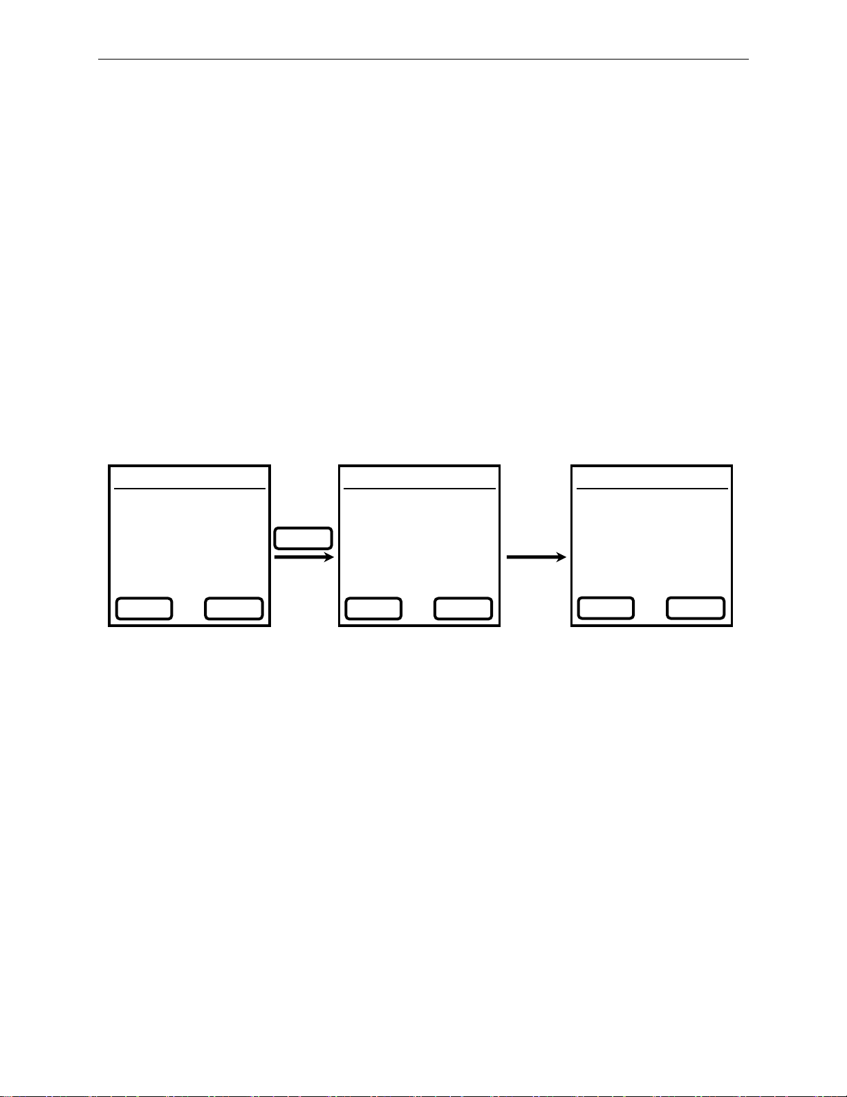
5.8.3 Pump Stall
The Pump Stall setting defines the current draw threshold the detects a blocked pump. During
normal operation if the gas inlet becomes plugged, the pump automatically turns off to avoid
further damage. To adjust the stall threshold, enter the Pump Stall menu and press ‘Change’.
When prompted, block the inlet with a finger for 5 seconds and let go. During the blockage the
pump should nearly stall and the current (I) reading should increase to a high value. The
Threshold will adjust itself automatically. If the new Threshold seems unsatisfactory for some
reason, press ‘Clear’ and repeat the 5-second blockage. When satisfied, press ‘Done’ followed by
‘Save’ to accept the new Pump Stall Threshold.
NOTE: A different Pump Stall Threshold must be set for each pump speed. The instrument
remembers the corresponding thresholds so that the user does not need to re-set the threshold
each time the pump speed is changed.
NOTE: The current (I) value depends on the Pump Speed and the condition of the inlet filter. At
high speed the I value is typically in the range 100-500, while at low speed it is typically 300-
900. If the I readings are at the high end or above these ranges, some maintenance should be
done such as replacing the filter, checking the gas flow path for obstructions or servicing the
pump.
5.8.4 Temperature Unit
The POLI is equipped with an internal thermometer whose display units can be chosen in either
Fahrenheit (°F) or Celsius (°C). The temperature readout can be viewed by scrolling through the
Main User Menu (Section 4.6).
5.8.5 Language
Language options English, Traditional Chinese and Simple Chinese are available.
Pump Stall
Current Pump
Thresh Setting:
I = 526
Thresh = 1235
Change
Done
Change
Clear
Done
Pump Stall
Please Block
Pump For 5 Sec:
I = 526
Thresh = 526
Block
Pump
Pump Stall
Please Block
Pump For 5 Sec:
I = 2350
Thresh = 1837
Clear
Done
Page 25
POLI User’s Guide
25
5.8.6 Backlight Mode
The LCD backlight can be set to illuminate automatically (in low ambient light conditions),
illuminate manually, or shut off. In Manual Backlight Mode the backlight can be turned on by
pressing either key. Using the Left [ /↓] key is convenient because it does not scroll to another
display (but does test the alarms). The backlight turns off automatically after 10 seconds if no
key is pressed.
5.8.7 LCD Auto Flip
The LCD can be configured to flip automatically when the POLI is positioned upside-down. The
auto-flip feature can be turned off.
5.8.8 Clock Set-up
The Clock Set-up menu is used to adjust the date and time as for any numerical inputs (see
Section 5.3.3). The date is in Month-Day-Year format and the clock is in 12-hour format. The
clock can also be set to synchronize with the PC, if that option is enabled using mPower Suite.
5.9 Wireless Set-up
Wireless communication will become operative in the MP400S and MP400H models (available
end of 2019). It is not included with MP400 or MP400P POLI models.
5.9.1 Register
Registering connects communication between the current instrument and the host module.
5.9.2 Host Module ID
The ID of the Host Module is displayed here.
5.9.3 Channel
The operating channel can be selected between 904.5 MHz, 915 MHz and 927 MHz.
Page 26
POLI User’s Guide
26
6. Data Communication
The mPower Suite software can be used to 1) download logged data, 2) upload configuration
parameters to the instrument, 3) display readings on a PC and download in real time and 4)
upgrade the instrument firmware. mPower Suite and instrument firmware can be downloaded
from our website at https://www.mpowerinc.com/software-downloads/ .
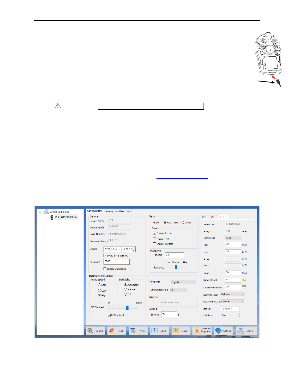
6.1 Connecting and Configuring
• Turn on the instrument, cycle through the Main User Mode and enter PC Comm.
• Connect the USB cable to the PC and the Micro-USB end to the instrument.*
WARNING! Connect only in non-hazardous environments!
• Start mPower Suite on the PC and click the “Search” button to find the instrument.
• Find the instrument in the left bar Device Connected list. Click on the S/N to get the
configuration file from the instrument.
• Edit the configuration parameters as desired including those under the tabs for each sensor in
the upper right. Click “Write” to upload the configuration to the instrument.
• “Read” allows downloading the current configuration file from the instrument.
• “Save” allows storing the current configuration file to the PC.
• “Load” allows calling up a stored configuration file from the PC to mPower Suite.
• To update the instrument firmware, select “Firmware Upgrade”. The firmware must first be
downloaded to the PC from the mPower website www.mPowerinc.com.
*NOTE: Any locally-obtained USB A to Micro B USB cable will work for battery charging, but will not
work for communication with mPower Suite software. The mPower USB cable P/N M-011-3003-000 is
required for a PC to recognize the instrument and communicate with mPower Suite.
mPower Suite Configuration Screen
Micro B (5-Pin)
to USB cable
Page 27
POLI User’s Guide
27
6.1.1 Configuration Details
These items can only be set up using mPower Suite and are not accessible in the instrument
Configuration Mode
• Bump and Calibration due notifications can be set between 1 and 360 days, but should be
limited to 180 days for all POLI instruments. Notifications are disabled by setting the
intervals to zero.
• Calibration Gas and a Measurement Gas can be selected from a list of a few hundred
compounds for PID and Pellistor LEL sensors. A correction factor is calculated based on the
calibration and measurement gas and applied to make the sensor display in concentration
equivalents of the measurement gas.
6.2 Datalog Retrieval
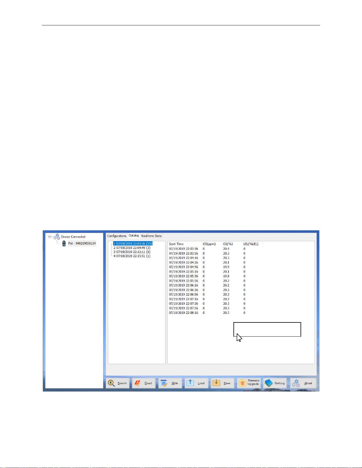
• To download the datalog from the instrument to the PC, select “Get Log”. This process can
take several minutes because datalogging is always on and large files can be created. The
datalog files will appear under the “Datalog” tab on the top of the screen. Below is a sample
screen of datalog information listing sample time and instantaneous readings. A new Single
Datalog file is created each time the instrument is turned on or the configuration is changed.
The middle panel shows the file start time and number of data points.
• To export data to a csv file readable by Excel or other spreadsheet software, move the cursor
over the right data panel and click the right mouse button, and then select either the current
Single Datalog file or all the stored data (Whole Datalog).
mPower Suite Datalog Screen
Export Single Datalog
Export Whole Datalog
Page 28
POLI User’s Guide
28
6.3 Real-Time Data
• (This function requires mPower Suite version 1.1.0.114 or later with NEO firmware v.1.9.1
or later.)
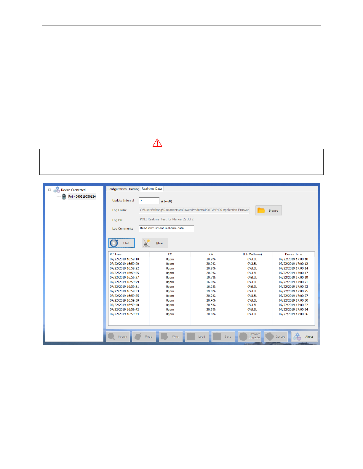
• To display a list of readings in real time, click on the “Real-time Data” tab on the top of the
screen. Enter the desired reading time interval, select a folder on the PC for storing the data,
and create a file name.
• Ensure that the POLI is connected and click “Start” to begin real-time monitoring. Select
“Stop” when finished and “Clear” to discard the data when no longer needed.
The data should be available as an Excel-readable .csv file in the folder selected. To separate the
data into columns in Excel, click on the “Data” menu on top and select “Text to Columns” to
convert.
WARNING!
Safety certificates for hazardous locations are invalid when the POLI is operated with a cable
connected to a computer or any other device. Perform real-time data transfers only in areas
known to have no risk of explosion hazard.
mPower Suite Real-time Data Screen
Page 29
POLI User’s Guide
29
7. Maintenance
The POLI requires little maintenance, aside from daily battery charging (see Section 2), regular
filter replacement, and sensor replacement as needed (1 to 3 years depending on sensor and use
conditions). Under extreme conditions, the pump or battery may need service or replacement.
7.1 Year of Manufacture
The year of manufacture can be identified from the fifth and sixth digits of the serial number,
where 00-99 indicates the manufacturing year is 2000 to 2099.
7.2 Replacing Filters
If the external filter is dirty or clogged, remove it by unscrewing it from the inlet. Discard it and
replace it with a new water-trap filter. Dirty filters can be recognized by symptoms such as:
• Visible filter discoloration
• Frequent pump stalls
• A high pump current (I) value shown in the Pump Stall menu
We recommend filter replacement at least every month for instruments that are used regularly,
and more frequently, possibly daily, when used under dusty or wet conditions.
IMPORTANT! A pumped POLI should not be calibrated or operated without a filter. Operation
without a filter may damage the instrument. The only exception to this requirement is for use
with reactive gases that may be partially lost on the filter.
7.3 Removing/Cleaning/Replacing Sensor Modules
WARNING!
Replace sensors only in non-hazardous locations.
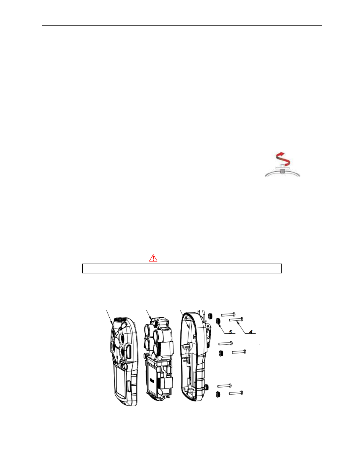
All sensors are located inside the sensor compartment on the top side of the POLI circuit board
assembly. They are accessed by removing the six screws in the back of the POLI and then
turning the instrument over and lifting off the sensor cover.
Page 30

POLI User’s Guide
30
1. Turn off the instrument.
2. Remove the six screws in the back of the instrument.
3. Turn the instrument over, lift off the front cover.
4. Carefully lift out each sensor you wish to inspect or replace.
5. Install the replacement sensor. Make sure the electrical contact pins are aligned with the
holes in the PC board and that the sensor is seated firmly. The location of a sensor does not
matter except that high-power sensors have double winged housings and can only be placed
in slots 1 and 2 with double-winged openings. Low-power sensors have single wings and
can be inserted into any of the four sensor slots. The firmware automatically recognizes the
sensor location.
6. Replace the cover and tighten the 6 screws.
IMPORTANT! Always perform a full calibration after replacing sensors.
7.4 Replacing Pump or Battery
For replacement of battery or pump, please contact an authorized mPower service center.
Page 31

POLI User’s Guide
31
8. Troubleshooting
Problem
Possible Reasons & Solutions
Cannot turn on power after
charging the battery
Reasons:
Defective charging circuit. Defective battery.
Solutions:
Try charging the battery again. Replace battery or charger.
Lost password
Solutions:
Call Technical Support at (408) 320-1266
Buzzer, LED lights, and
vibration motor inoperative
Reasons:
Buzzer and/or other alarms disabled. Bad buzzer.
Solutions:
Check under ‘Alarm Settings’ in Configuration Mode that
buzzer and/or other alarms are not turned off. Call
authorized service center.
Pump failed message
Pump alarm
Reasons:
Inlet probe blocked. Direct connection to calibration gas
outlet before the regulator is opened. External filter plugged
with dirt or liquid. Water condensed in the internal gas
distribution lines. Bad pump or pump circuit.
Solutions:
Remove the blocking materials and then press [+/OK] key
to reset the pump alarm. Replace the contaminated external
filter. Be careful not to allow water condensation inside the
unit. Replace or rebuild the pump (by Service Center).
Cannot communicate with PC
Reasons:
Wrong cable.
Solutions:
Use mPower USB cable P/N M-011-3003-000.
For replacement parts please contact an authorized mPower Service Center.
Page 32
POLI User’s Guide
32
9. Technical Specifications
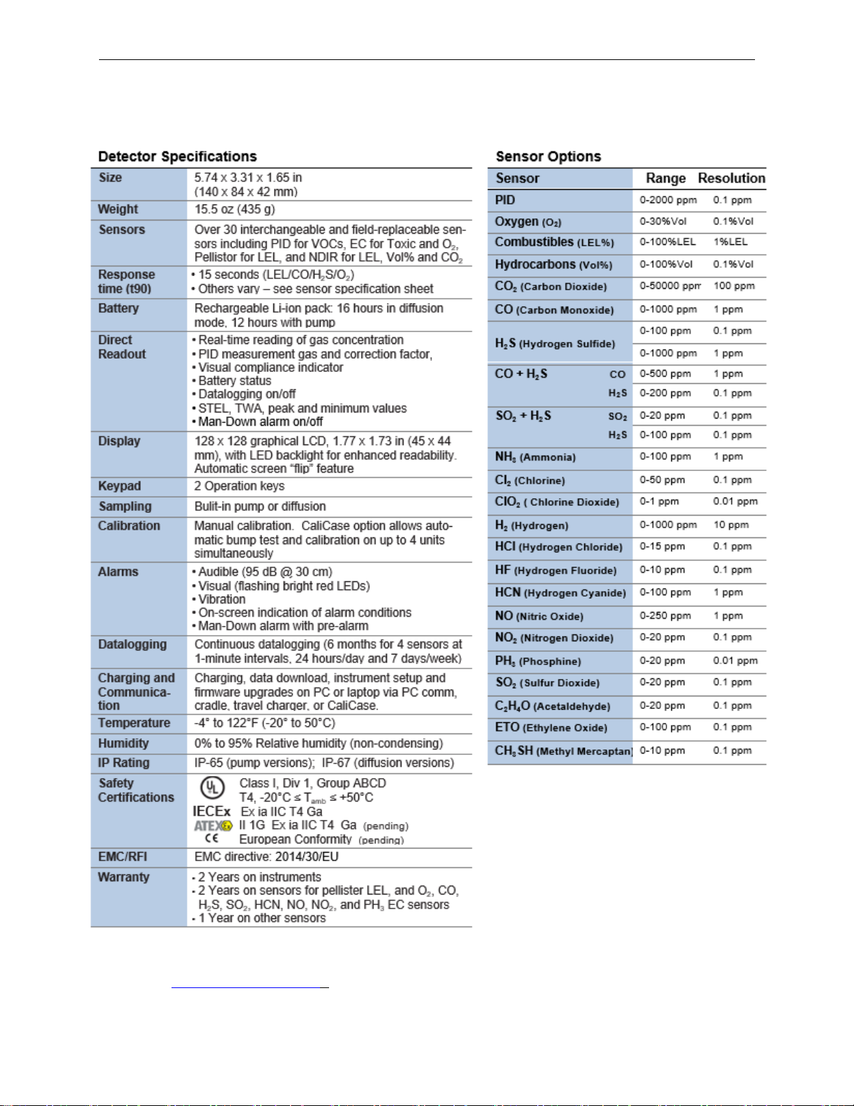
All specifications and listed sensors are subject to change without notice. Please check for
updates at www.mpowerinc.com .
Page 33

POLI User’s Guide
33
Recommended Gas Span Concentrations
Note: Use balance gas of air if available, otherwise use nitrogen balance gas
Sensor
Range
Calibration Gas
PID
0.1-2000 ppm
100 ppm Isobutylene
LEL/O2/CO/H2S (mPower Std 4-gas mix)
50%LEL/18% O2/50 ppm CO/15 ppm H2S
Oxygen (O2)
0.1-30%Vol
18 %Vol
Combustibles (LEL%)
1-100%LEL
50 %LEL (2.5 %Vol Methane)
Hydrocarbons (Vol%)
0.1-100%Vol
20 %Vol Methane
CO2 (Carbon Dioxide)
100-50000 ppm
5000 ppm (0.5 %Vol) Carbon Dioxide
CO (Carbon Monoxide)
1-1000 ppm
50 ppm CO
H2S (Hydrogen Sulfide)
0.1-100 ppm
25 ppm H2S
H2S (Hydrogen Sulfide)
1-1000 ppm
100 ppm
CO + H2S CO
H2S
1-500 ppm
50 ppm
0.1-200 ppm
25 ppm
SO2 + H2S SO2
H2S
0.1-20 ppm
5 ppm
0.1-100 ppm
25 ppm
NH3 (Ammonia)
1-100 ppm
50 ppm
Cl2 (Chlorine)
0.1-50 ppm
10 ppm
ClO2 ( Chlorine Dioxide)
0.01-1 ppm
0.5 ppm (Requires ClO2 generator)
H2 (Hydrogen)
10-1000 ppm
700 ppm
HCl (Hydrogen Chloride)
0.1-15 ppm
10 ppm
HF (Hydrogen Fluoride)
0.1-10 ppm
25 ppm NO ppm
HCN (Hydrogen Cyanide)
1-100 ppm
10 ppm
NO (Nitric Oxide)
1-250 ppm
25 ppm
NO2 (Nitrogen Dioxide)
0.1-20 ppm
5 ppm
PH3 (Phosphine)
0.01-20 ppm
5 ppm
SO2 (Sulfur Dioxide)
0.1-20 ppm
5 ppm
C2H4O (Acetaldehyde)
0.1-20 ppm
10 ppm Ethylene Oxide
ETO (Ethylene Oxide)
0.1-100 ppm
10 ppm
CH3SH (Methyl Mercaptan)
0.1-10 ppm
5 ppm
Page 34

POLI User’s Guide
34
Technical Support and mPower Contacts
mPower Electronics Inc.
3046 Scott Blvd. Santa Clara, CA 95054
Phone: (408) 320-1266
Fax: (669) 342-7077
[email protected]
www.mpowerinc.com
 Loading...