

Page 1
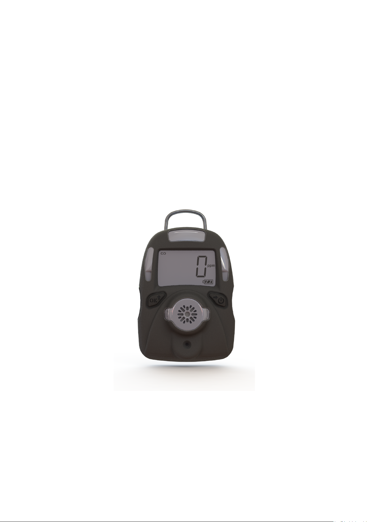
MP100
User’s Guide
Rev. C
July 2017
Page 2

MP100 User’s Guide
Contents
Read Before Operating ................................................................................................................... 2
General Information ....................................................................................................................... 3
User Interface .................................................................................................................................. 4
Display .............................................................................................................................................. 5
Using MP100 .................................................................................................................................... 6
Turn the unit on ....................................................................................................................... 6
Warm up sequence .................................................................................................................. 6
Normal mode ........................................................................................................................... 7
Real time reading ............................................................................................................ 7
STEL screen......................................................................................................................7
TWA screen ...................................................................................................................... 7
Peak screen ...................................................................................................................... 7
Min screen (for Oxygen sensor only) ............................................................................. 8
Turn the unit off ...................................................................................................................... 8
Config mode ..................................................................................................................................... 9
Enter Config mode .................................................................................................................. 9
Sensor calibration.....................................................................................................................9
Calibration process................................................................................................................10
Zero calibration ..................................................................................................................... 11
Span calibration .................................................................................................................... 11
Change alarm limit ............................................................................................................... 11
Change span value ................................................................................................................ 12
Change display unit .............................................................................................................. 13
Vibrator enable/disable ......................................................................................................... 13
Power on zero enable/disable ............................................................................................... 13
Fast power on enable/disable ............................................................................................... 14
Reset config ............................................................................................................................ 14
Exit Config mode ................................................................................................................... 14
Maintenance .................................................................................................................................. 15
Replace the battery ............................................................................................................... 15
Replace the sensor filter ........................................................................................................ 15
Replace the sensor ................................................................................................................. 16
Ordering information ................................................................................................................... 18
Specifications ................................................................................................................................. 19
Sensor configuration......................................................................................................................20
Alarm signal summary ................................................................................................................. 21
Trouble shooting.............................................................................................................................23
1
Page 3

MP100 User’s Guide
Read Before Operating
This manual must be carefully read by all individuals who have or will have the responsibility of
using, maintaining, or servicing this product. The product will perform as designed only if it is
used, maintained, and serviced in accordance with the manufacturer’s instructions.
Warning
Never operate the monitor when the cover is removed.
Remove the monitor cover and battery only in area known as non-hazardous.
Use only mPower’s lithium battery part number 1.17.02.0002 (3.6V, 2700mAH, AA size).
This instrument has not been tested in an explosive gas/air atmosphere having an oxygen
concentration greater than 21%.
Substitution of components will impair suitability for intrinsic safety.
Substitution of components will void warranty.
It is recommended to bump test with a known concentration gas to confirm the instrument is
functioning properly before use.
Before use, ensure that the ESD film on the display is not damaged or peeling.
Avertissement:
N'utilisez jamais le moniteur lorsque le couvercle est enlevé.
Retirer le couvercle du moniteur et la batterie uniquement dans une zone connue comme non
dangereuse.
Utilisez uniquement le numéro de pièce de la batterie au lithium mPower 1.17.02.0002 (3.6V,
2700mAH, taille AA).
Cet instrument n'a pas été testé dans une atmosphère explosive gaz / air ayant une concentration
en oxygène supérieure à 21%.
La substitution de composants compromettra l'aptitude à la sécurité intrinsèque.
La substitution des composants annulera la garantie.
Il est recommandé de tester avec un gaz de concentration connu pour confirmer que l'instrument f
onctionne correctement avant de l'utiliser.
Avant de l’utiliser, assurez-vous que le film ESD sur l'écran n'est pas endommagé ou épluché.
Proper Product Disposal at The End Of Life
The Waste Electrical and Electronic Equipment(WEEE) directive (2002/96/EC) is
intended to promote recycling of electrical and electronic equipment and their
components at end of life . This symbol (crossed-out wheeled bin) indicates
separate collection of waste electrical and electronic equipment in the EU
countries. This product may contain one or more Nickel-metal hydride (NiMH),
Lithium-ion, or Alkaline batteries. Specific battery information is given in this
user guide. Batteries must be recycled or disposed of properly. At the end of its
life, this product must undergo separate collection and recycling from general or
household waste. Please use the return and collection system available in your
country for the disposal of this product.
2
Page 4

MP100 User’s Guide
General Information
UNI (MP100) is a single sensor, portable, personal toxic gas monitor. It displays gas
concentration continuously on a big segment LCD. It also monitors STEL, TWA, peak and min
(for O2 only) value of the gas, and can be displayed on demand.
High、Low、STEL、TWA alarm threshold values are configurable. The shell is made of high
strength, durable material. Two key operation, simple to use. Sensor and battery can be replaced
easily. Calibration is also very convenient.
3
Page 5
MP100 User’s Guide
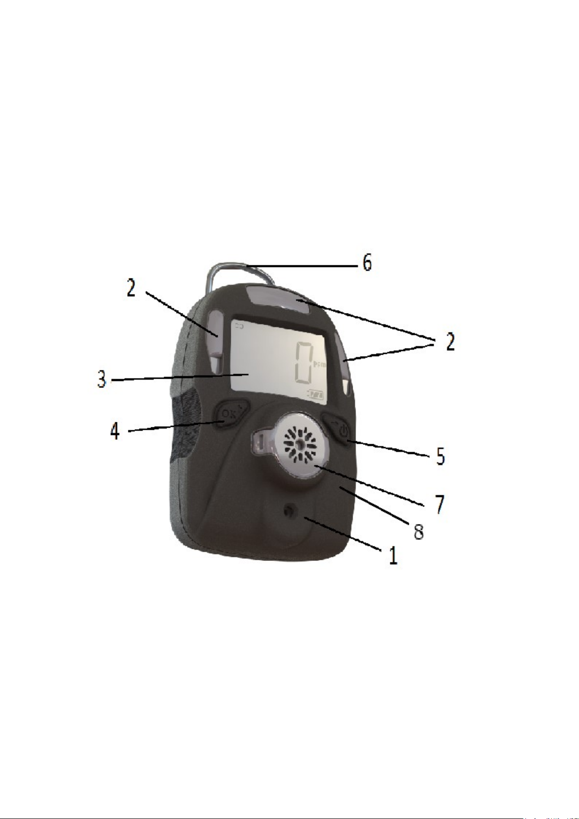
User Interface
1. Buzzer
2. LED alarm window
3. LCD
4. Left Key (Confirm/Number increasing)
5. Right Key (Power/ Cursor moving)
6. Alligator clip
7. Sensor
8. Vibrator
4
Page 6

MP100 User’s Guide
Display
1. Gas name, includes: CO, H2S, SO2, O2, VOC
2. Question mark
3. OK
4. Gas unit, includes: x10-6, ppm, %, mg/m3, µmol/mol
5. Battery
6. HIGH, LOW, STEL, TWA alarm
7. Span calibration
8. Zero calibration
9. Number
5
Page 7
MP100 User’s Guide
Using MP100
Turn the unit on
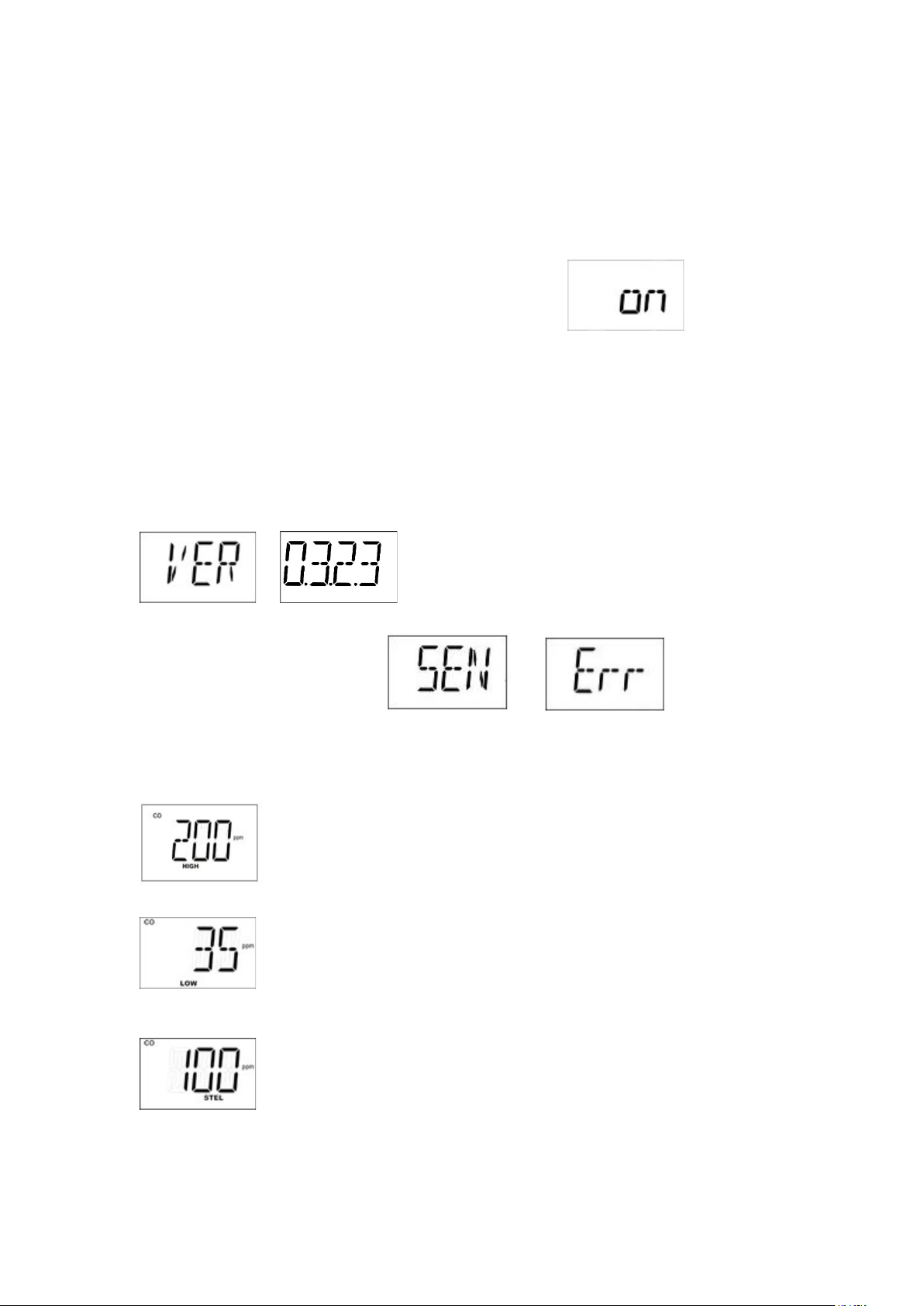
Press and hold the Right Key for 3 seconds, until LCD displays , buzzer beeps,
green LED flashes, then release the button, the unit is powered on.
Warm up sequence
After powered on, the unit enter warm up and self test sequence, show the firmware version as
follows:
If the sensor is not able to be identified by the instrument or is not installed into the instrument,
then the screen toggles between and .Otherwise, the
following values will be shown accordingly:
High alarm threshold value:
Low alarm threshold value:
STEL (short-term exposure limit) alarm threshold value:
6
Page 8
MP100 User’s Guide
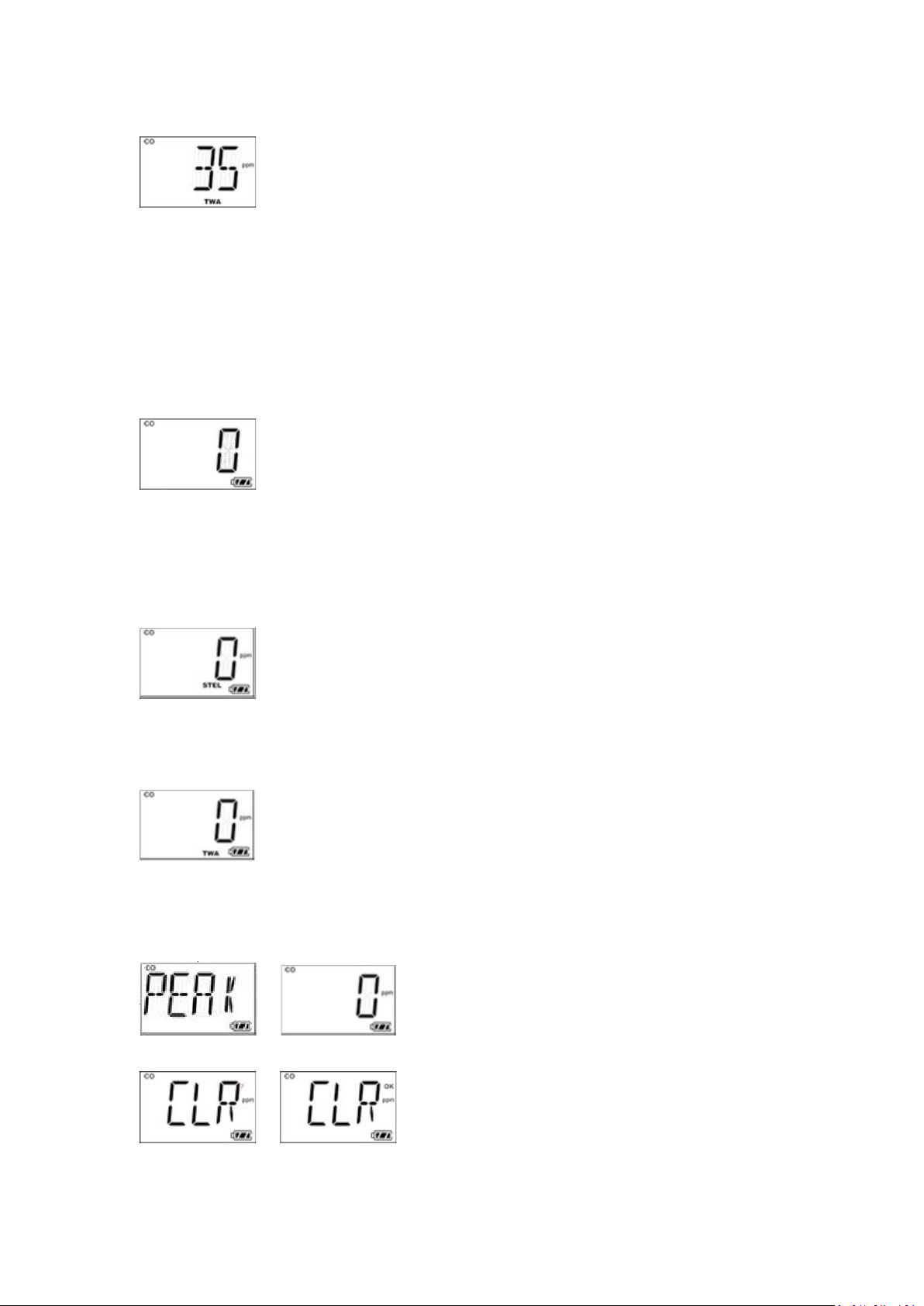
TWA (time-weighted average) alarm threshold value:
Normal mode
Real time reading
The unit enter normal mode, start monitoring gas concentration and display on the LCD screen.
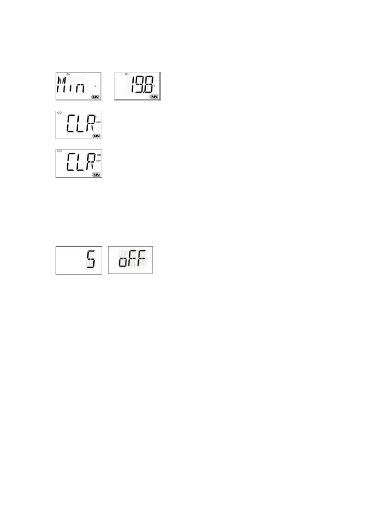
User can check some other values like STEL,TWA, PEAK, and MIN (for O2 only) by pressing the
Right Key.
STEL screen:
TWA screen
Peak screen
Press the Left Key to clear peak value
Press the Left Key again, peak value is cleared.
7
Page 9
MP100 User’s Guide
Min screen (for Oxygen sensor only)
Press the Left Key to clear min value
Press the Left Key again, minimum value is cleared
Turn the unit off
In normal display mode, press and hold the Right Key, then the unit will display 5 seconds count
down, with red LEDs flash and buzzer beeps once per second.
After 4 short flashes and beeps, unit gives a long flash and beep, LCD displays “Off”, the unit is
powered off.
8
Page 10
MP100 User’s Guide
Config mode
In Config mode, user can do calibration, change parameters for the unit. In general, use the Left
Key to increase number or confirm, use the Right Key to move cursor or move to the next
programming item.
Enter Config mode
Press and hold the Left Key and the Right Key together for 3 seconds, then the unit enter Config
mode.
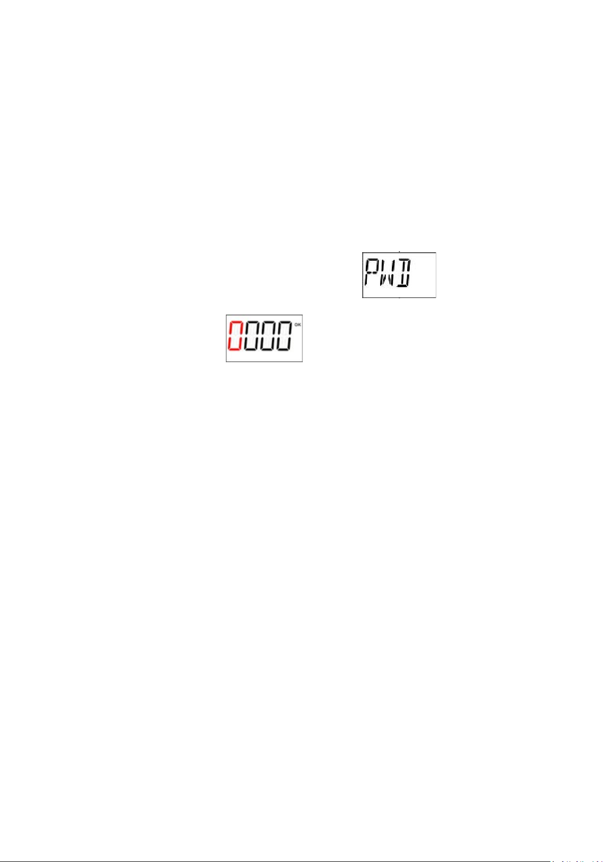
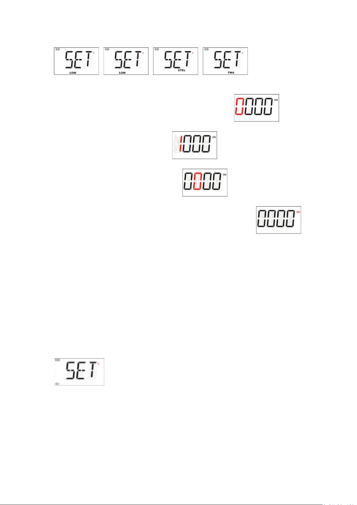
The Config mode is password protected, LCD displays to prompt enter
password. The screen displays , with one digit flashing in red, to let user input
password.
To input password, use the Left Key to increase the number, use the Right Key to move cursor.
After all four digits are input, the cursor will move to “OK”, use the Left Key to finish password
input and enter the Config mode.
If the digit input is mistaken, use the Right Key to move cursor between four digit and “OK” mark,
to change the input.
Sensor calibration
Before the unit can monitor gas correctly, it need to know the metric, this is done by zero
calibration and span calibration.
9
Page 11
MP100 User’s Guide
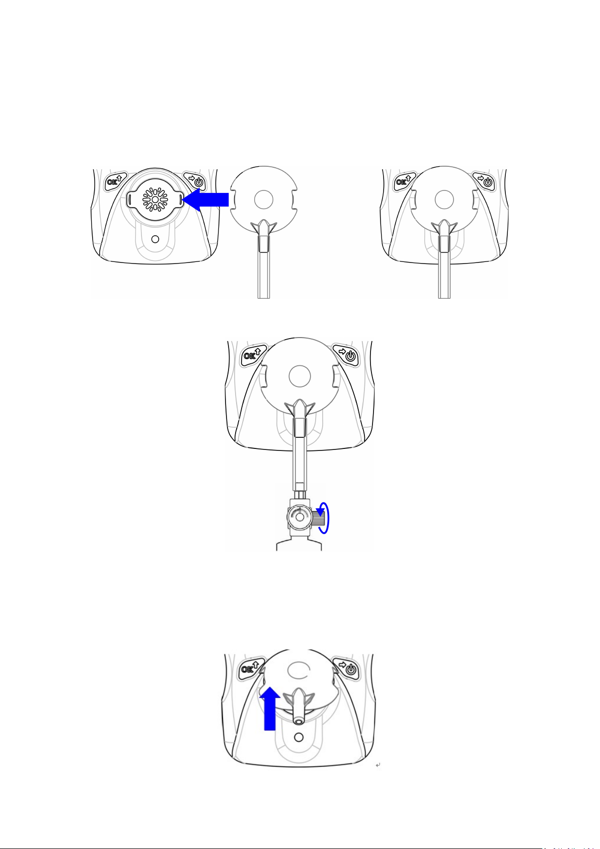
Calibration Process
1. Attach the Calibration Adapter over the inlet port on the front of MP100 by pressing it into
place.
2. Enter the calibration function, open the gas cylinder, press the Left Key, and start calibration
after countdown.
3. Take off the Calibration Adapter (according to the direction of the icon and suggest to make use
of the Calibration Adapter’s inlet), and complete calibration. When monitoring, never operate the
MP100 with the Calibration Adaptor attached. The MP100’s sensor operates by diffusion. If the
Calibration Adapter is attached during normal operation, inconsistent and lower-than-normal
readings will occur because of decreased concentration of the gas being monitored.
10
Page 12
MP100 User’s Guide
Zero calibration
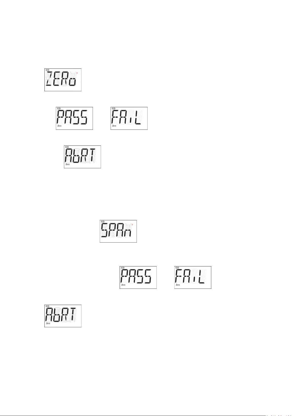
Zero calibration is to get the base line for the sensor, it is done in fresh air. When LCD displays
, press the Left Key to start zero calibration. Unit will start 15 seconds
count-down, after count-down is finished, zero calibration result will be displayed on the LCD,
pass or fail .
If user don’t want to do zero calibration during 15 seconds count, press the Right Key, LCD
displays , zero calibration is aborted.
Span calibration
Span calibration is to get the metric of the sensor to the gas, it is done with a known concentration
gas. When LCD displays , apply the known gas to the unit, then press the Left
Key to start span calibration. Unit will start count-down, the count-down time depends on
different sensors ( normally is 60 seconds), after count-down is finished, span calibration result
will be displayed on the LCD, pass or fail .
If user don’t want to do span calibration during count-down, press the Right Key, LCD displays
, span calibration is aborted.
Change alarm limit
All the preset alarm limit: High, Low, STEL, TWA, can be changed. When LCD displays:
11
Page 13
MP100 User’s Guide
, , , , press the Left Key
to change the corresponding alarm limit, the value change process are similar.
First the current setting value is displayed, with the first digit flashing: .
Use the Left Key to increase the current digit, , cycle from 0 to 9.
Use the Left Key to move cursor to the next digit:
After all digits are done, use the Right Key to move cursor to “OK” symbol, ,
press the Left Key to confirm the changing.
* MP100 will show “Err”, if the input data is invalid as follows,:
- Low alarm setting is bigger than high alarm setting.
- High alarm setting is smaller than low alarm setting.
- Input data is bigger than measuring range.
Change span value
The span calibration preset value can also be changed, the change process is similar with the alarm
limit. But the new span will not take effect until user successfully completes a span calibration
next time.
*MP100 will show “Err”, if the input data is invalid as follows:
- Span setting is smaller than 5% measuring range or bigger than measuring range.
- For Oxygen sensor, span setting is bigger than 19.0 .
12
Page 14
MP100 User’s Guide
Change display unit
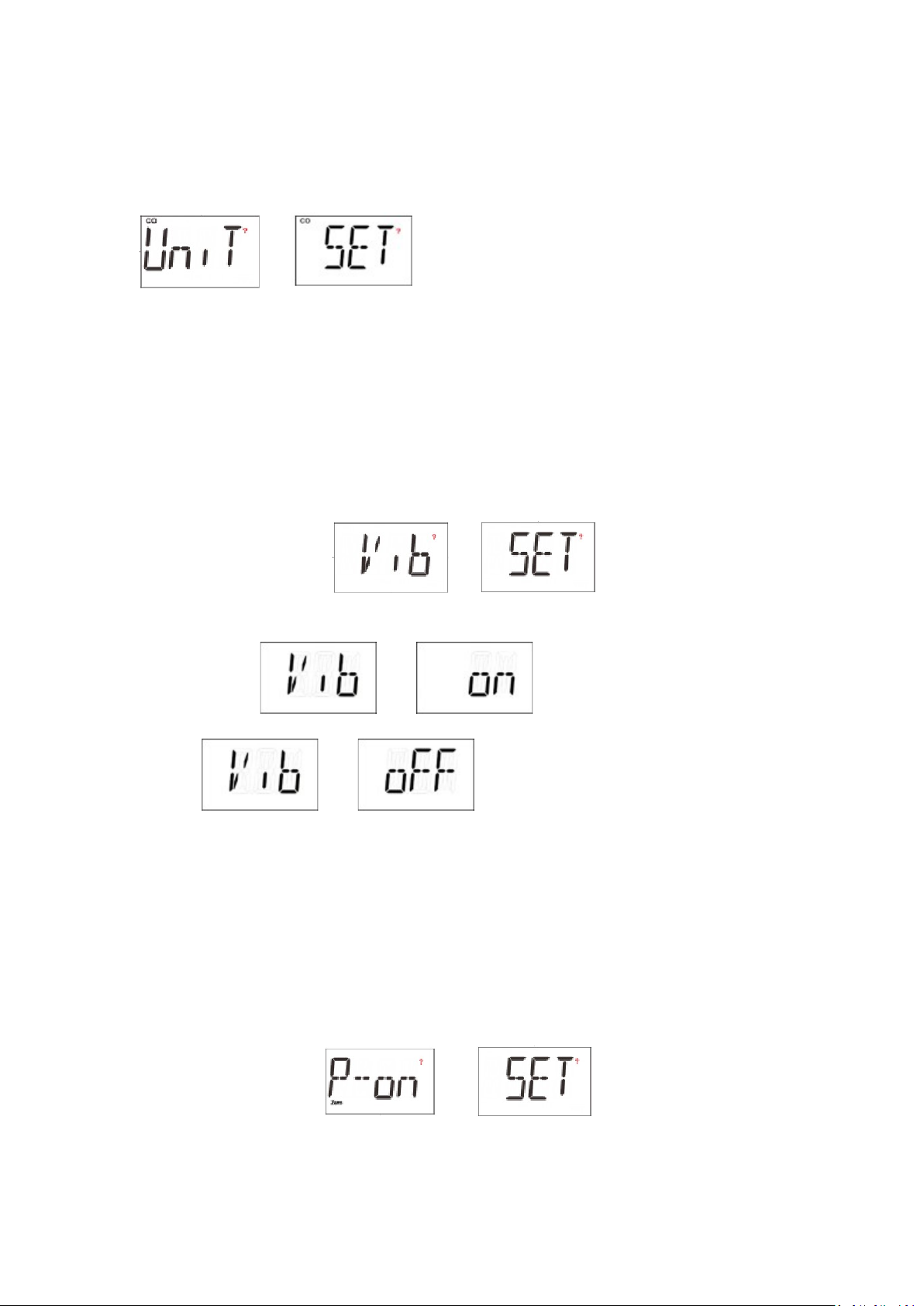
MP100 supports different gas unit, to change gas unit, when LCD toggles between
and , press the Left Key to change gas unit. The supported
units for current sensor are all displayed on the LCD, the current selected unit is blinking. Use the
Right Key to change unit, use the Left Key to confirm selected gas unit.
Vibrator enable/disable
The vibrator consumes a lot of power, it can be disabled to save battery power, to extend the
battery life.
When LCD toggles between and , press the Left Key to
change the vibrator enable/disable status. The current vibrator status is displayed on the LCD,
toggling between and if the vibrator is enabled, or toggling
between and , if the vibrator is disabled. Use the Right Key
to change the enable/disable status, and use the Left Key to confirm the change.
Power on zero enable/disable
Sensor base line may have some change due to environment (temperature, humidity…), that will
require a zero calibration. MP100 can do zero calibration every time unit is powered on, this
feature can be enabled/disabled.
When LCD toggles between and , press the Left Key to go to
change power on zero calibrations enable/disable status. The current enable/disable status is
displayed on the LCD, use the Right Key to change, use the Left Key to confirm the change.
13
Page 15
MP100 User’s Guide
Fast power on enable/disable
If fast startup is enabled, the screens showing High/Low/STEL/TWA alarm threshold value will be
skipped during warm up sequence.
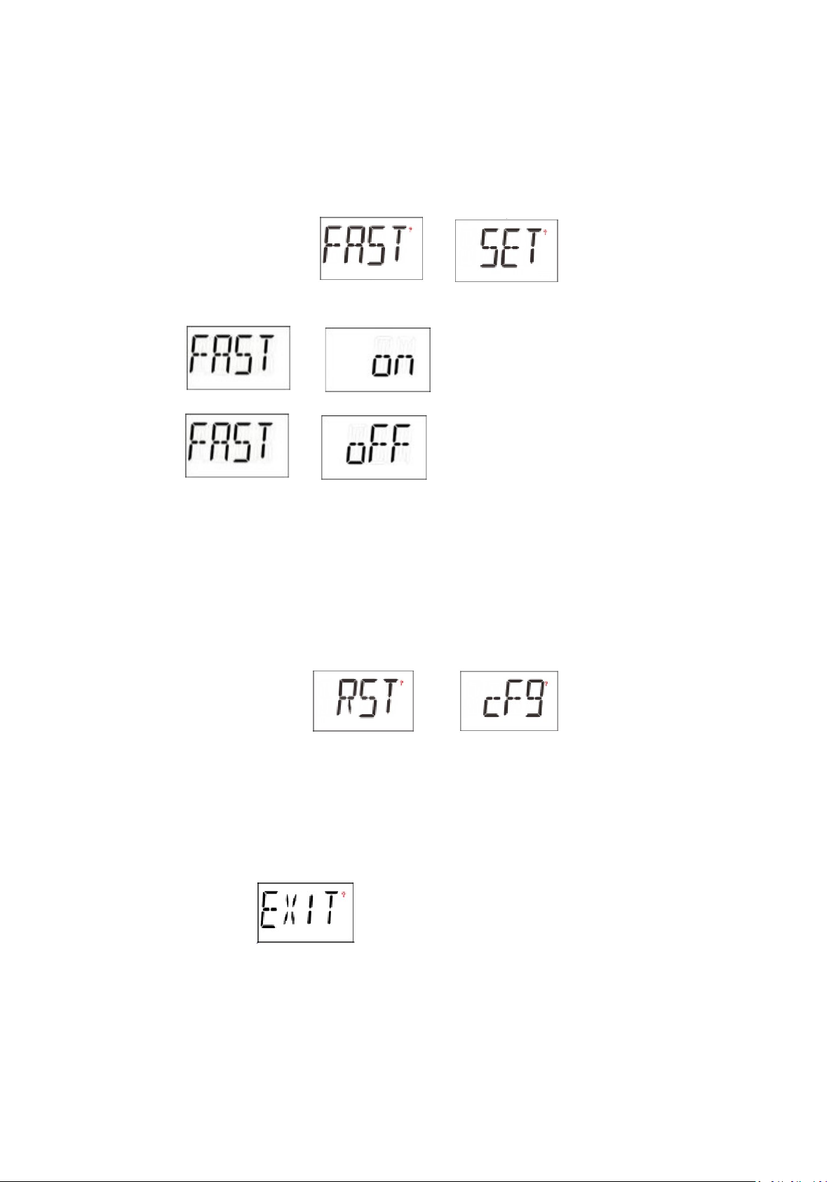
When LCD toggles between and , press the Left Key to
change fast startup enable/disable status. The current status is displayed on the LCD, toggling
between and if the fast startup is enabled, or toggling
between and if the fast startup is disabled. Use the Right
Key to change the enable/disable status, use the Left Key to confirm the change.
Reset config
If the unit parameter is messed up and user do not know how to set them back, user can use reset
config to make all the parameters back to factory default.
When LCD toggles between and , press the Left Key to
enter config reset menu, press the Left Key to confirm config reset.
Exit Config mode
When LCD displays , press the Left Key exit from Config mode back to normal
mode.
14
Page 16
MP100 User’s Guide
Maintenance
Maintenance should be performed only by a qualified person who
has proper training and fully understands the contents of the manual.
Replace the battery
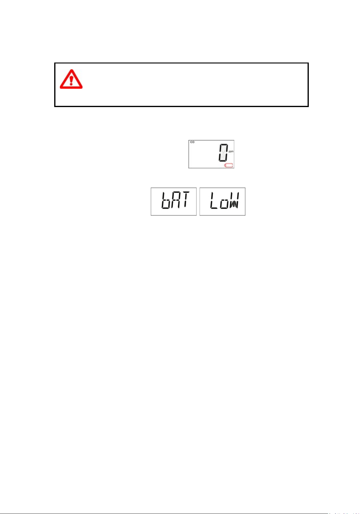
When the battery’s charge is low, LCD displays , battery low alarm will be
triggered once every minute. User need to replace the battery.
When battery is dead, LCD displays , battery dead alarm will
be triggered once every second. User need to replace the battery.
To replace battery:
1) Turn off the MP100.
2) Place the MP100 face down on a soft surface.
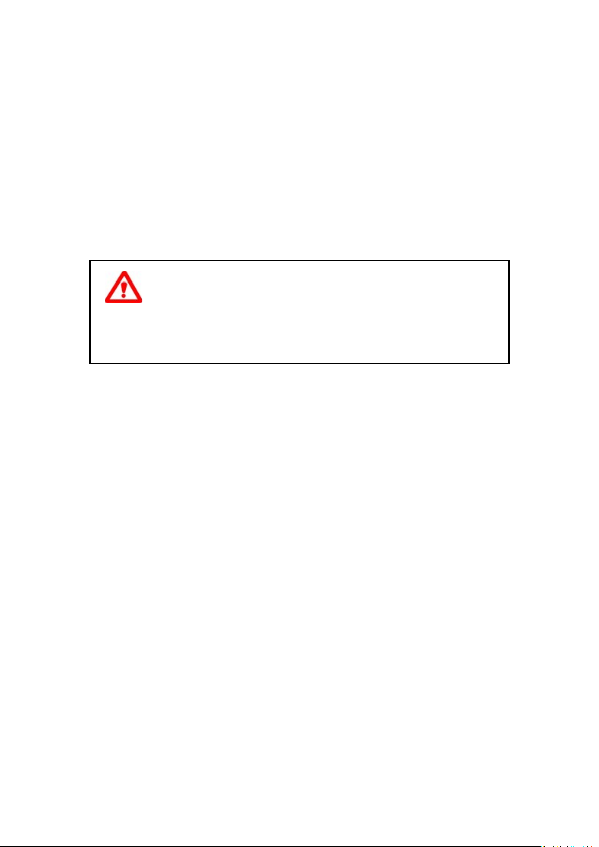
3) Use a screwdriver to loosen each of the four screws by turning them counterclockwise.
4) Remove the top cover after carefully unplug the buzzer connector.
5) Slide the battery out of its compartment.
6) Place the new battery into the compartment with its “+” end oriented toward the “+” on the
printed circuit board.
7) Plug the buzzer connector and install the top cover back.
8) Install the screws back from the back cover.
Replace the sensor filter
A “peel-and-stick” filter should be used on the MP100 in order to keep debris from fouling the
sensor. Sheets of 5 filters are available. When the filter appears dirty, replace it with a new one and
dispose of the dirty filter.
1) Turn off the MP100.
2) Place the MP100 face down on a soft surface.
3) Use a screwdriver to loosen each of the four screws by turning them counterclockwise.
4) Remove the top cover after carefully unplug the buzzer connector.
5) Peel a filter from the sheet and center it over the sensor. Gently press down.
6) Plug the buzzer connector and install the top cover back.
7) Install the screws back from the back cover.
15
Page 17
MP100 User’s Guide
Replace the sensor
MP100 models are designed so that you can easily change the sensor.
1) Turn off the unit.
2) Place the MP100 face down on a soft surface.
3) Use a screwdriver to loosen each of the four screws by turning them counterclockwise.
4) Remove the top cover after carefully unplug the buzzer connector.
5) Replace the old sensor with a new one. Make sure the pins are not bent or corroded . Align the
pins to the corresponding holes and push the sensor straight in . The sensor should fit flush
against the printed circuit board.
6) Plug the buzzer connector and install the top cover back.
7) Install the screws back from the back cover.
Sensors are not interchangeable. Use only mPower’ s
sensors, and use only the sensor type specified for your MP100 monitor.
Use of non-mPower’s components will void the warrenty and can
compromise the safe performance of this product.
16
Page 18
MP100 User’s Guide
Caution
Change battery only in area known to be non-hazardous.
Use only mPower’s battery, PN: 1.17.02.0002.
Attention:
Changez la batterie uniquement dans une zone connue pour être non
dangereuse.
Utiliser uniquement la batterie mPower PN: 1.17.02.0002.
17
Page 19

MP100 User’s Guide
Ordering information
Kit Package
MP100 instrument with sensor,
AA size lithium battery with alligator clip
One mini-CD with instruction manual
Calibration adapter
Calibration Kits(Optional):
Test gas (for sensor as specified)
Gas regulator with flow controller
Hard transport case
Multi-unit charging and calibration station
Year of manufacturing
To identify the year of manufacturing, please refer to the serial number of the instrument.
The fifth to sixth digit in the serial number indicates the year of manufacturing. 00~99
indicates the manufacturing year is 2000 to 2099.
18
Page 20

MP100 User’s Guide
Specifications
Size 3.46 x 2.44 x 1.3 in.
(88 x 62 x 33mm)
Weight 4.4 oz (125g)
Temperature
Humidity 5 ~ 95% relative humidity(non-condensing)
Alarm type High alarm, low alarm, STEL alarm, TWA alarm,
Alarm signal Audible: 90dB @ 30cm
Calibration 2 point calibration, zero and span, power on zero
Event log Up to 10 alarm events
Response
time(T90)
IP rating IP67
EMI/RFI Compliant with EMC 2004/108/EC
Certifications UL/cUL:
Battery Replaceable AA size Lithium battery,
Sensor CO/H2S expected operating life 5 years in air, others 2
Warranty
-4℉ ~ 122℉(-20℃ ~ 50℃)
adjustable.
Over range alarm, battery low alarm.
Visual: Bright red LED.
Sense: Built in vibrator.
(need user confirm).
20 seconds(only for CO/H2S/O2)
Class I, Group A, B, C, D
Class II, Group E,F,G
Class III
T4, -20° C≤ Tamb≤ +50° C
3 years if used within specs
years
CO/H2S 2 years if used within specs,others 1 year
19
Page 21
MP100 User’s Guide
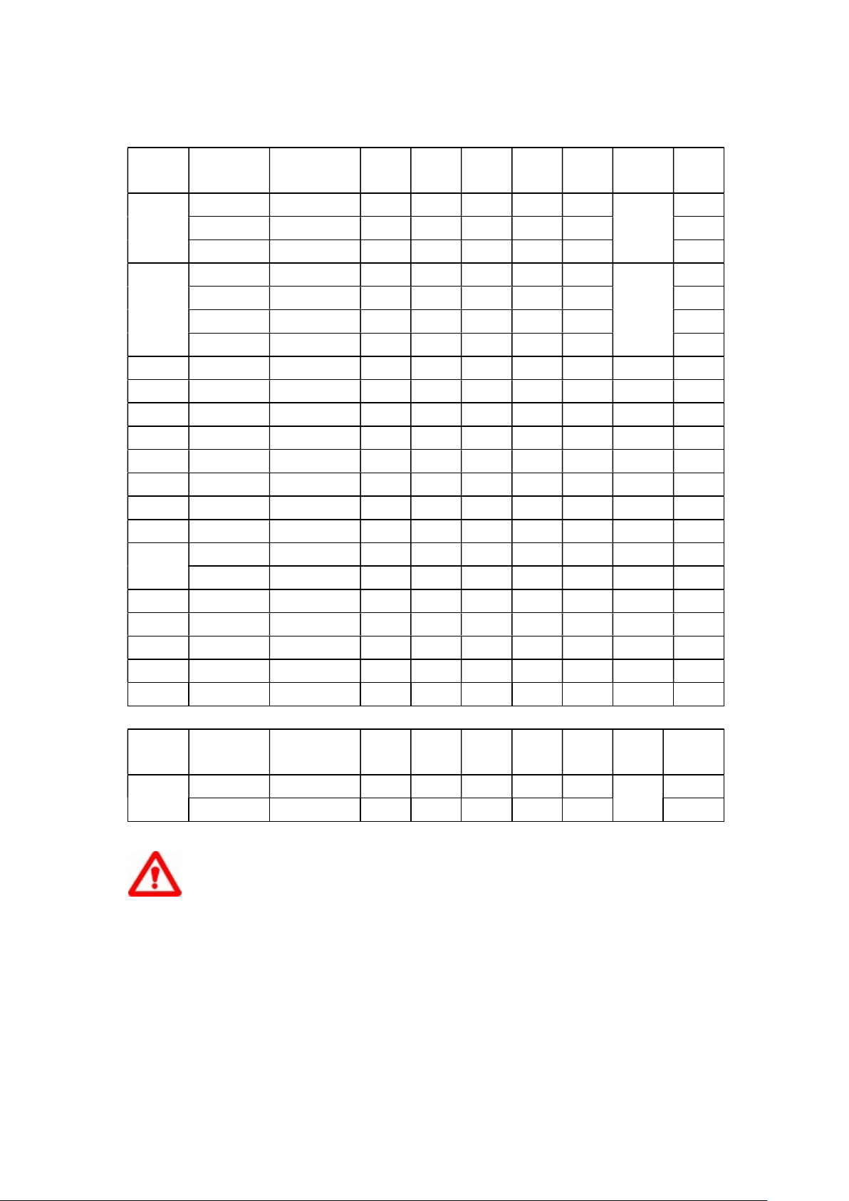
Sensor configuration
Sensor Range
(ppm)
CO
H2S
NH3 0-50 1 50 25 50 35 25 Orange 150
Cl2 0-10 0.1 10 0.5 5 1 0.5 Orange 30
ClO2 0-1 0.01 0.5 0.2 0.5 0.3 0.1 Orange 120
HCN 0-100 1 10 4.7 50 4.7 4.7 Orange 200
NO 0-250 1 25 25 50 25 25 Orange 30
NO2 0-20 0.1 5 1 10 1 1 Orange 30
PH3 0-5 0.01 5 1 2 1 0.3 Orange 60
SO2 0-20 0.1 5 2 10 5 2 Orange 15
ETO
O3 0-1 0.02 1 0.1 0.2 0.1 0.1 Orange 60
HF 0-10 0.1 6 2 6 6 3 Orange 90
HCl 0-15 0.1 10 2 5 5 1 Orange 90
CH3SH 0-10 0.1 5 0.5 5 0.5 0.5 Orange 35
C2H4O
Sensor Range
O2
0-1999 1 100
0-1000 1 100
0-500 1 50 35 200 100
0~50 0.1 25 10 20 15 10 Light
0-100 0.1 25 10 20 15 10 20
0~200 0.1 25 10 20 15 10 20
0~1000 1 25 10 20 15 10 30
0-100 0.1 10 1 5 5 1 Orange 120
0-200 0.1 10 5 10 5 1 Orange 120
0-20 0.1 5 2 10 5 2 Orange 120
(%)
0 - 25 0.1 18 19.5 23.5
0 - 30 0.1 18 19.5 23.5
Resolution
(ppm)
Resolution
(%)
Span
(ppm)
Span
(%)
Low
(ppm)
Low
(%)
High
(ppm)
35 200 100
35 200 100
High
(%)
STEL
(ppm)
STEL
(%)
TWA
(ppm)
TWA
(%)
- - Dark
- - 20
Panel
Ring
35 Red 20
35 20
35 20
Blue
Panel
Ring
Blue
T90(s)
20
T90(s)
20
Caution
Use only mPower sensors.
Call for availability.
20
Page 22
MP100 User’s Guide
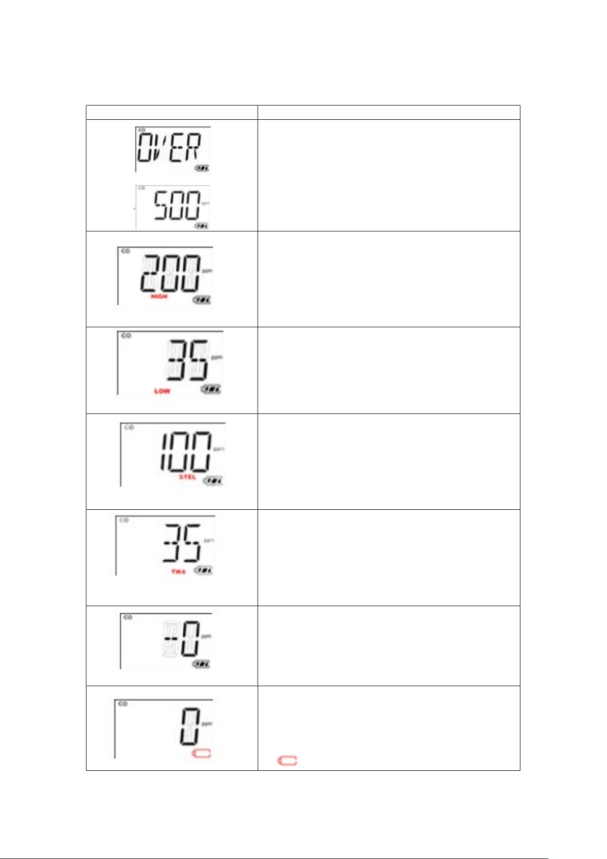
Alarm signal summary
LCD Display Reason/Alarm Signals
Over range:
Buzzer 3 beep per second
LED 3 flash per second
1 vibration per second
“OVER” and “500” 1 flash per second
High alarm:
Buzzer 3 beep per second
LED 3 flash per second
1 vibration per second
“HIGH” 2 flash per second
Low alarm:
Buzzer 2 beep per second
LED 2 flash per second
1 vibration per second
“LOW” 2 flash per second
STEL alarm:
Buzzer 1 beep per second
LED 1 flash per second
1 vibration per second
“STEL” 2 flash per second
TWA alarm:
Buzzer 1 beep per second
LED 1 flash per second
1 vibration per second
“TWA” 2 flash per second
Negative drift alarm:
Buzzer 1 beep per second
LED 1 flash per second
1 vibration per second
Battery empty alarm:
Buzzer 1 beep per minute
LED 1 flash per minute
1 vibration per minute
1 flash per minute
21
Page 23
MP100 User’s Guide
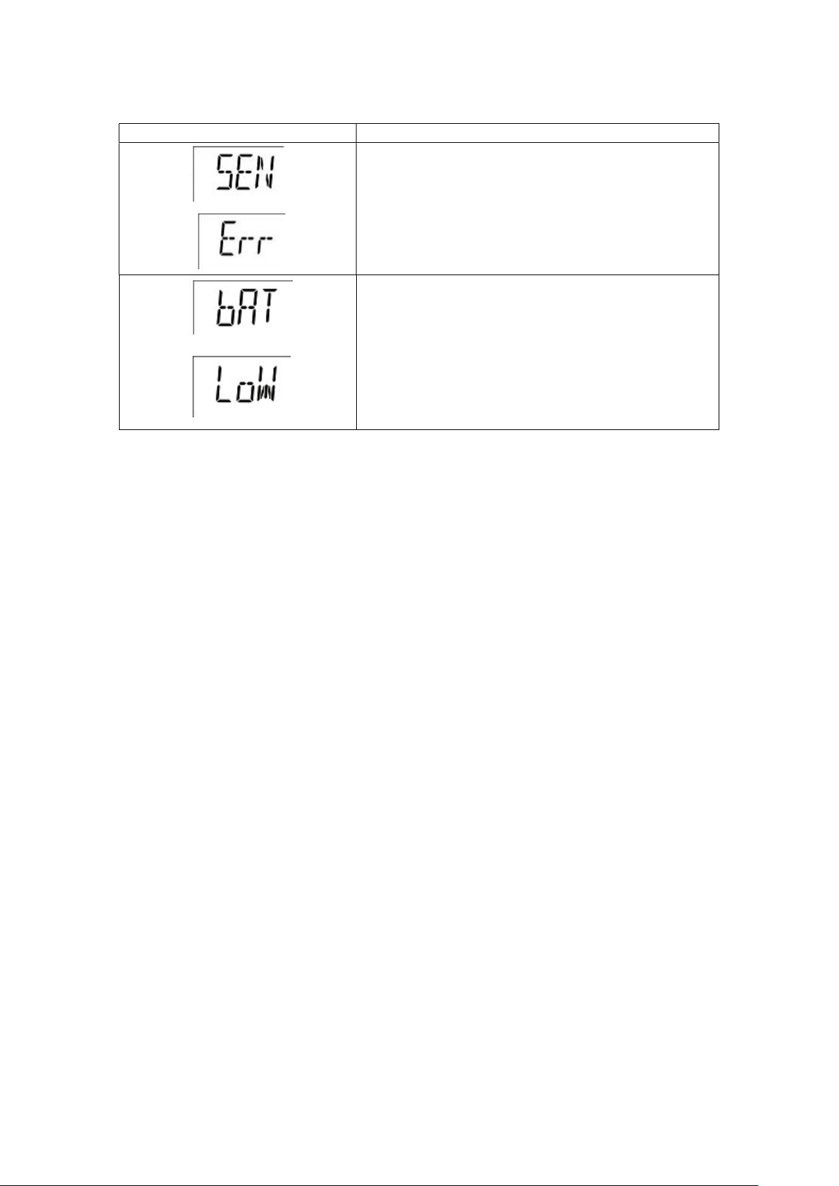
LCD Display Reason/Alarm Signals
Sensor error:
Buzzer 1 beep per second
LED 1 flash per second
“SEN Err”1 flash per second
Battery low alarm:
Buzzer 1 beep per second
LED 1 flash per second
“bAT LoW”1 flash per second
22
Page 24

MP100 User’s Guide
Trouble shooting
Problem Possible reason Solution
Can not turn on unit Battery not installed Install battery.
Depleted or defective battery Replace battery.
Reading abnormally low Calibration Adapter is attached. Remove Calibration Adapter.
Incorrect calibration. Calibrate the MP100.
Buzzer, LED, or vibration
alarm inoperative
Bad buzzer, LEDs, or vibration
alarm.
Blocked alarm port Unblock alarm port.
Call authorized service center.
23
Page 25

MP100 User’s Guide
mPower Electronics (Shanghai) Co.,Ltd.
www.mpower-electronics.com
TechSupport: [email protected]
24
 Loading...