

Page 1
MPLAB® PICkitTM 4 In-Circuit Debugger
C: 10 M: 100 Y: 100 K: 20 PMS: 7621C
Standard
QUICK START GUIDE
GETTING STARTED
1
Install the Latest Software
Download the MPLAB X IDE software from www.microchip.com/mplabx and install onto your computer. The installer
automatically loads the USB drivers. Launch MPLAB X IDE.
2
Connect to Target Device
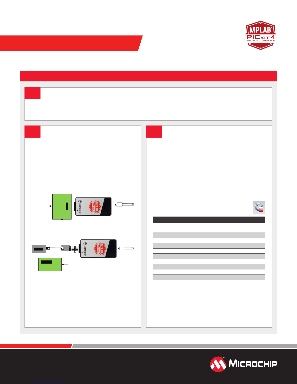
1. Connect the MPLAB PICkit 4 to the computer
using the supplied Micro-B USB cable.
2. Attach the communications cable between the
debugger and target board.
3. Connect external power to target board.
Typical Debugger System – Device with
On-Board Debug Circuitry
Target Device
Power
Target Board
Micro-B USB
from computer
Alternative Debugger System – ICE Device
Header
Device-ICE
Transition Socket
Target Board
Adapter
Power
if needed
Micro-B USB
from computer
3
Create, Build and Run Project
1. Refer to the MPLAB X IDE User's Guide or online help
for instructions to install language tools, create or
open a project, and congure project properties.
2. Check that the conguration bits in your code match
the Recommended Settings below.
3. To execute your code in Debug mode, perform a
debug run. To execute your code in Non-Debug
(release) mode, perform a run. To hold a device in
Reset after programming, use the Hold in Reset icon
in the toolbar.
Recommended Settings
Component Setting
Oscillator
Power Supplied by target
WDT Disabled (device dependent)
Code-Protect Disabled
Table Read Protect Disabled
LVP Disabled
BOD Vdd > BOD Vdd min.
JTAG Disabled
AVdd and AVss Must be connected
PGCx/PGDx Proper channel selected, if applicable
Programming Vdd voltage levels meet programming spec
Note: See MPLAB PICkit 4 In-Circuit Debugger online help for more information.
• OSC bits set properly
• Running
*External target board power supply to be provided by user.
www.microchip.com/pickit4
Reserved Resources
For information on reserved resources used by the
debugger, see the MPLAB
PICkit
4 In-Circuit Debugger
online help.
Page 2
ADDITIONAL INFORMATION
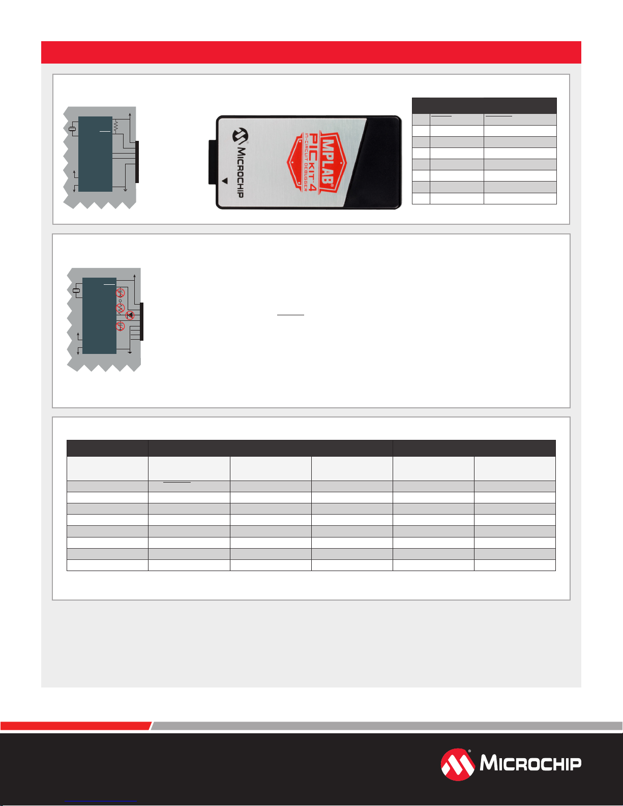
Target Application PC Board
Incorrect
Target Application PC Board
Correct
Typical cable
length is 6 inches
Circuitry and Connector Pinouts
DD
Target V
(tVDD)
VDD
VPP/MCLR
Device
PGC
PGD
50 kΩ
Typical
2
1
5
Connect
4
3
Pin 1 to Pin 1
6
7
8
SS
V
XTAL
Target Application
DD
AV
AVSS
Target Circuit Design Precautions
• Do not use pull-ups on PGC/PGD: they will disrupt the voltage levels, since these lines have
(tVDD)
programmable pull-down resistors in the debugger.
• Do not use capacitors on PGC/PGD: they will prevent fast transitions on data and clock lines
2
1
5
4
3
6
7
8
during programming and debug communications.
• Do not use capacitors on MCLR: they will prevent fast transitions of VPP. A simple pull-up
resistor is generally sucient.
• Do not use diodes on PGC/PGD: they will prevent bidirectional communication between the
debugger and the target device.
• Do
not exceed recommended cable lengths: Refer to the Hardware Specication of the
MPLAB PICkit 4 online help or user's guide for cable lengths.
VPP/MCLR
XTAL*
Device
Target Application
AVDD**
SS**
AV
PGC
PGD
V DD
V
Target V
SS
DD
V
Typical 6-Pin ICSP Pinout
Pin Target MPLAB® PICkit 4
1 MCLR/Vpp NMCLR
2 Vdd Target Vdd
3 Vss (ground) Ground
4 PGD (ICSPDAT) PGD
5 PGC (ICSPCLK) PGC
6 Do Not Connect Do Not Connect
7 Reserved for Future use
8 Reserved for Future use
Pinouts for Additional Interfaces
MPLAB® PICkit 4 Debugging and Programming Data Stream
Pin # ICSP MIPS EJTAG Cortex® SWD
1 Vpp/NMCLR
2 Vdd VIO_REF VTG VTG
3 GND GND GND GND
4 PGD TDO SWo MISO
5 PGC TCK SWCLK SCK
6 AUX NRESET NRST (SCK)
7 TDI TDI TX MOSI
8 TMS TMS SWDIO RX SS
** Target device must be running with an oscillator for the debugger to function as a debugger.
*** If the device has AVdd and AVss lines, they must be connected for the debugger to operate.
The Microchip name and logo, the Microchip logo, MPLAB and PICkit are registered trademarks of Microchip Technology Incorporated in the U.S.A. and other countries. All other trademarks mentioned
herein are property of their respective companies. © 2018, Microchip Technology Incorporated. All Rights Reserved. 2/18 DS50 002721A
DMCI/DGI
U(S)ART/CDC
DGI SPI
www.microchip.com/pickit4
 Loading...