

MPL MCDISK-E, MCDISK-E-1, MCDISK-E-5 User Manual
© 1997 by MPL AG
1
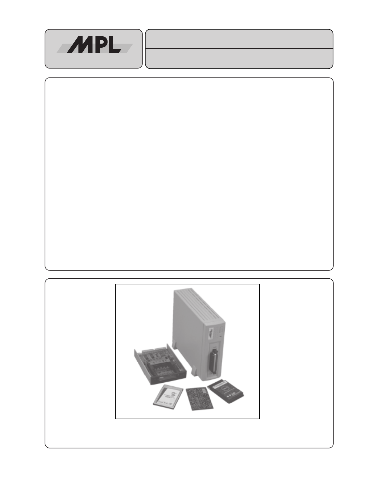
MCDISK-E
USER'S MANUAL
PCMCIA/JEIDA CARD READER/WRITER WITH SCSI INTERFACE
The MCDISK-E (Memory Card Disk) is a two slot card reader/writer for PCMCIA/JEIDA compatible memory cards. Two card
slots allow for simultaneous use of memory cards. The MCDISK-E can handle a wide variety of cards of any size: SRAM, ROM,
OTP, E(E)PROM, FLASH, I/O and PC-ATA disks. To interface those cards to the host equipment it has an SCSI interface. The
SCSI interface is widely used for connecting mass storage devices like hard disks to microcomputers.
A memory card can be thought of as an extremely fast disk storage device, because there are no latencies for moving
mechanical parts like read/write heads. In all other aspects however, a disk device and a memory card are much the same.
The MCDISK-E exists in two versions. The first one is equivalent to a 3.5" Floppy drive which can be easily incorporated into
OEM products. The second one is a desktop case with built-in power supply for easy connection to all computers with a SCSI
interface. However, although the reader/writer device is compact and economically priced, no concessions have been made
in its performance. It provides a fully professional yet highly economic solution to demands for data storage in harsh
environment. This makes the MCDISK-E ideal for use in many industrial and business applications with SCSI data input and/
or output.
MEH-10000-003 Rev. H
References :
MCDISK-E-1 Open frame Reader/Writer for JEIDA/PCMCIA Memory Cards +5V / +12VDC
MCDISK-E-5 Desktop case Reader/Writer for JEIDA/PCMCIA Cards 100-240VAC / 50-60 Hz
TECHNICAL FEATURES
• Size and mounting compatible to 3.5" floppy disk drive
(open-frame with 1” height) for MCDISK-E-1
• Desktop case for horizontal or vertical mounting
for MCDISK-E-5
• Interfaces PCMCIA/JEIDA Memory Cards to any system
with a SCSI interface
• Double card slot
• Separate SCSI ID for each slot can be configured
• SRAM, ROM, OTP, E(E)PROM, FLASH and I/O card support
• PC-ATA disk support
• Card sizes 512 Byte up to 64 MByte (PC-ATA: 4 GByte)
• Powerless card inserting of PCMCIA cards
• Memory card types I, II and III are supported
• Supports direct access to entire memory card (raw access)
• Hybrid card (mixed memory types) and multiple partition
support
• All PCMCIA operations handled automatically by the unit
• Built-in socket and card services feature transparent access
to card data for PCMCIA-unaware host systems
• High data security through block check capability
• Local 68HC11 processor
• SCSI-2 interface with a WD 33C93 SCSI controller
• Standard SCSI command set
• Low power consumption, typ. 120mA (no card inserted)
• Fast 2 Mbytes/s transfer rate
High-Tech Made in Switzerland
2
MCDISK-E
High-Tech Made in Switzerland
TABLE OF CONTENTS
INTRODUCTION ................................................................................................................................................................... 3
I. ABOUT THIS MANUAL............................................................................................................................................ 3
II. SAFETY PRECAUTIONS AND HANDLING ........................................................................................................... 3
III. EQUIPMENT SAFETY ........................................................................................................................................... 3
1. COMMON FOR ALL MCDISK-E ........................................................................................................................................ 4
1.1 COMPATIBILITY................................................................................................................................................... 4
1.2 OPERATION......................................................................................................................................................... 4
1.3 PCMCIA CARD TYPES........................................................................................................................................ 4
1.4 CARD HANDLING ............................................................................................................................................... 4
1.4.1 INSERTING A CARD ............................................................................................................................. 4
1.4.2 EJECTING A CARD ............................................................................................................................... 5
1.5 LED INDICATORS ............................................................................................................................................... 5
1.5.1 BASIC INDICATIONS............................................................................................................................. 5
1.5.2 ERROR SIGNALLING............................................................................................................................ 5
1.6 DRIVER SOFTWARE ........................................................................................................................................... 5
2. MCDISK-E-1 OPEN FRAME.............................................................................................................................................. 6
2.1 SPECIFICATIONS ................................................................................................................................................ 6
2.1.1 PHYSICAL DIMENSIONS...................................................................................................................... 6
2.2 ELECTROSTATIC DISCHARGE (ESD) PROTECTION...................................................................................... 6
2.3 SET-UP................................................................................................................................................................. 7
2.3.1 SET-UP OVERVIEW .............................................................................................................................. 7
2.3.2 PARTS LOCATIONS .............................................................................................................................. 7
2.4 SCSI ID AND OPTIONAL FEATURES ................................................................................................................. 8
2.4.1 SCSI ID................................................................................................................................................... 8
2.4.2 DUAL SCSI ID FEATURE ...................................................................................................................... 8
2.4.3 OPTIONAL FEATURES .........................................................................................................................8
2.5 TERMINATION ..................................................................................................................................................... 8
2.5.1 SCSI BUS TERMINATION ..................................................................................................................... 8
2.5.2 TERMINATOR POWER (TERMPWR) ................................................................................................... 8
2.6 MOUNTING ................................................................................................................... .......................................9
2.6.1 GENERAL HINTS ..................................................................................................................................9
2.6.2 HARDWARE REQUIRED ...................................................................................................................... 9
2.6.3 MOUNTING THE UNIT........................................................................................................................... 9
2.7 POWER AND SCSI BUS CONNECTION........................................................................................................... 10
2.7.1 SCSI BUS CONNECTION ...................................................................................................................10
2.7.2 SCSI Chain .......................................................................................................................................... 10
2.7.3 POWER CONNECTION....................................................................................................................... 10
2.8 DC VOLTAGE MONITOR ...................................................................................................................................10
2.9 MECHANICAL DIMENSIONS ............................................................................................................................ 11
3.MCDISK-E-5 DESKTOP VERSION .................................................................................................................................. 12
3.1 SPECIFICATIONS .............................................................................................................................................. 12
3.1.1 PHYSICAL DIMENSIONS.................................................................................................................... 12
3.2 RADIO AND TELEVISION INTERFERENCE..................................................................................................... 12
3.3 SET-UP...............................................................................................................................................................13
3.3.1 SET-UP OVERVIEW ............................................................................................................................ 13
3.3.2 PARTS LOCATIONS ............................................................................................................................ 13
3.3.3 SCSI ID.................................................................................................................................................13
3.4 TERMINATION ................................................................................................................................................... 13
3.4.1 SCSI BUS TERMINATION ................................................................................................................... 13
3.5 OPTIONAL FEATURES...................................................................................................................................... 13
3.6 MECHANICAL DIMENSIONS ............................................................................................................................ 13
DISCLAIMER ....................................................................................................................................................................... 16
3
High-Tech Made in Switzerland
MCDISK-E
INTRODUCTION
I. ABOUT THIS MANUAL
This manual is written for use by technical personnel responsible for integrating the MCDISK-E reader/writer into their
system. The manual assists the installation procedure by
providing the information necessary to handle, configure and
mount the MCDISK-E reader/writer.
The MCDISK-E reader/writer is designed to work with most
host systems which are fitted with an SCSI interface. It is a
simple procedure to set up the unit, nevertheless, before
attempting any installation, please read through all applicable
sections of this manual and follow the instructions herein.
The following publications relate closely to this product and
supply information about PCMCIA and SCSI interface. For
those involved in writing drivers or special applications that
directly interface to the MCDISK-E, a Technical Reference
Manual provides information required to drive the MCDISK-E
on the SCSI command level.
• MCDISK Technical Reference Manual (supplied by MPL
AG or your local MCDISK supplier). The MCDISK Technical Reference Manual is also available on the internet
under "http://www.mpl.ch" in PDF format.
• PCMCIA PC Card Standard (July 1993, Release 2.1)
• ANSI SCSI-2 Standard (X3.131-199x, Revision 10h)
II. SAFETY PRECAUTIONS AND HANDLING
For personal safety and safe operation of the MCDISK-E,
follow all safety procedures described here and in other
sections of the manual.
• Power must be removed from the computer system before
installing (or removing) the MCDISK-E reader/writer to
prevent the possibility of personal injury (electrical shock!)
and/or damage to the unit.
• Handle the unit carefully, i.e. dropping or mishandling the
read/write unit can cause damage to internal assemblies.
• Read and follow all the instructions and warnings described herein.
• Keep the MCDISK away from all sources of liquids, such
as coffee cups, drinking glasses, washing facilities etc.
• Protect the MCDISK from damp or wet weather.
• Keep this manual available for reference.
For your protection and that of your MCDISK disconnect the
power input immediately if any of the following conditions
exists:
• The power input cable has been damaged.
• Something has been spilt onto the case.
• The MCDISK has been damaged in any way, e.g. through
dropping.
• The MCDISK has been exposed to excess moisture or
rain.
• You suspect that the unit requires servicing or repair.
WARNING: There are no user-serviceable components on the MCDISK-E!
III. EQUIPMENT SAFETY
Great care is taken by MPL that all it's products are thoroughly
and rigorously tested before leaving the factory to ensure that
they are fully operational and conform to specification. However, no matter how reliable a product, there is always the
remote possibility that a defect may occur. The occurrence of
a defect on this device may, under certain conditions, cause
a defect to occur in adjoining and/or connected equipment. It
is the users responsibility to ensure that adequate protection
for such equipment is incorporated when installing this
device. MPL accepts no responsibility whatsoever for such
kind of defects, however caused.
4
MCDISK-E
High-Tech Made in Switzerland
1. COMMON FOR ALL MCDISK-E
1.1 COMPATIBILITY
MCDISK-E operates with various system platforms using
standard driver software. Some host systems do not fully
support MCDISK-E and require special driver software. MPL
AG provides a "Technical Note for MCDISK" that reflects the
actual status of software support for different host systems.
Additionally, this Technical Note lists PCMCIA card type
compatibility tests performed by MPL AG or MCDISK users.
1.2 OPERATION
This chapter provides information about the use of the
PCMCIA cards and the LED indicators.
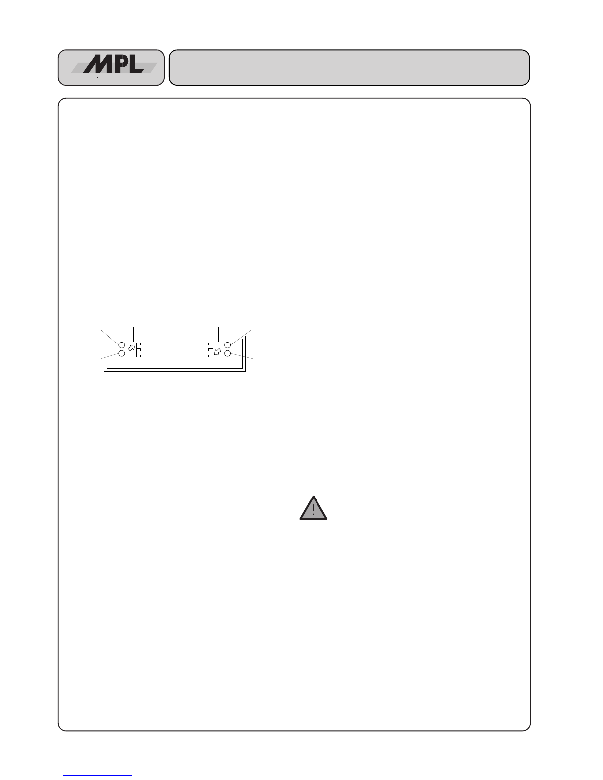
The illustration below identifies the items visible on the front
panel of the MCDISK-E.
Fig.1.2: Front view
1.3 PCMCIA CARD TYPES
The MCDISK-E has been designed to accept three different
PCMCIA card types:
• Type I: Thickness 3.3 mm, no raised substrate area
• Type II: Thickness 5.0 mm, 48 mm wide raised substrate
area
• Type III: Thickness 10.5 mm, 51 mm wide raised
substrate area
The lower card slot accepts all three types of cards. Due to the
front panel cutout, the upper card slot only accepts type I and
II cards.
Type I and II cards can be inserted simultaneously in the lower
and upper slot. Type III cards must be inserted in the lower
slot, likewise occupying the space of the upper slot.
1.4 CARD HANDLING
Follow the instructions as described in this section when
inserting and ejecting PCMCIA cards. Refer to Figure 5 to
locate indicated items.
1.4.1 INSERTING A CARD
When inserting a card into one of the card slots of the MCDISKE, care must be taken to ensure that the card is inserted
correctly. Follow these steps to insert the card:
1. Orientate the memory card so that the printed surface (e.g.
with manufacturer name/logo) is up and the 68-pin connector points towards the MCDISK-E card slot. Note that
some cards have an arrow indicating direction of insertion.
2. Insert the card into the slot. It should slide easily into the
slot until approx. 15 mm remain exposed and the card
comes to a soft stop. At this point gentle pressure is
required to make the final connection between the
memory card and the card slot connector.
If the card comes to a sudden stop earlier than described
above, do not press any further! Key guides on the card
and in the card slot ensure that the card cannot be fully
inserted (does not reach the connector) when inserted in
the wrong way! Remove the card, check orientation and
try again.
3. When the card is fully inserted a small portion of the card
will remain exposed from the card slot opening. The red
LED on the front of the MCDISK-E will go off indicating that
the card is present. If the red LED remains lit then the card
has not been inserted correctly or cannot be operated by
the MCDISK-E (e.g. bad card type).
WARNING: Do NOT use excessive force to overcome any resistance when inserting the card. This
should not be necessary and will severely damage
both the card and the MCDISK-E.
Power LED
(green)
Lower card
eject button
Error LED
(red)
Upper card
eject button
Access LED
upper slot
Access LED
lower slot
5
High-Tech Made in Switzerland
MCDISK-E
1.4.2 EJECTING A CARD
Each card slot has its own card eject button. The eject button
at the left hand side of the card slots serves the upper card slot,
the eject button on the right hand side the lower card slot.
Arrows are printed on the eject buttons that point to the card
slot they serve.
To remove the PCMCIA card push the corresponding eject
button. The card is released from the connector inside and it
may now be pulled free.
CAUTION: Do NOT attempt to pull the card free without first
pressing the card eject button!
Do NOT attempt to remove the card when the yellow LED is
lit (see also next section)!
WARNING: Avoid the situation where foreign objects, dust,
liquids etc. can enter the MCDISK-E through the card slot
opening. This can cause severe damage.
1.5 LED INDICATORS
The MCDISK-E is equipped with four LED indicators. Refer
to Figure 1.2 for the location of the indicators.
1.5.1 BASIC INDICATIONS
The green LED (upper left hand side) is the power indicator.
It is lit whenever the unit is turned on.
The yellow (right hand side) LEDs are the access indicators
for the upper and lower slot. They are illuminated whenever
an access to the memory card in the corresponding slot takes
place.
Don’t eject the PCMCIA card when the yellow LED is lit!
The red (left hand side) LED is the status indicator. It is
illuminated when the MCDISK-E is not operable due to one
of the following reasons:
• There is no card inserted. If a card is inserted correctly, the
red LED will go off.
• There is a card inserted, but it cannot be accessed by the
MCDISK-E. Such errors can have various causes: the unit
is attempting to write to a write-protected or read-only
card, unknown I/O card, hardware error on a memory card,
etc.
During start-up (power up or SCSI bus reset), the MCDISKE performs some internal self tests. When everything is okay,
the red and both yellow indicators will flash twice simultaneously to indicate proper start-up and proper SCSI connection.
1.5.2 ERROR SIGNALLING
In case of an error, the red and both yellow indicators will show
a diagnostic status:
• All three indicators remain unlit: Ensure that the unit is
connected correctly to a powered SCSI bus. Likewise the
unit cannot start-up when the SCSI bus is not or not
correctly terminated (TERMPWR OK?). If the SCSI bus is
okay and the indicators still remain unlit, there may be a
hardware problem and the unit requires service.
• All three indicators flash only once and then remain unlit:
The internal RAM test has failed. The unit requires service.
• The error LED flashes repeatedly: There is a SCSI hardware problem.
• The error LED double-flashes repeatedly: This indicates a
severe SCSI bus protocol error that prevents the MCDISK from continuing SCSI operation. The MC-DISK
needs to be reset to recover from this error. If the error is
permanent, check SCSI cabling, terminators and SCSI
ID's.
• The error LED triple-flashes repeatedly: The ROM contents are not okay. The unit requires service.
• The LEDs show some other pattern than those listed
above: There is a serious hardware problem, and the unit
needs to be returned to your local MCDISK-E supplier for
repair.
1.6 DRIVER SOFTWARE
If your MCDISK supplier has provided a driver software
package with your MCDISK-E, this must be loaded on the host
computer before commencing to work with the MCDISK-E.
Follow the instructions provided with the driver and/or the
procedures laid down for installing software on the host
computer provided in the host computer documentation.
If you have an Internet access you can visit our Web site at
http://www.mpl.ch
There you will find different tools, drivers and additional
documentation especially for MCDISKs.
 Loading...