

MPL IDE2PCC User Manual
IDE2PCC
User Manual
IDE2PCC
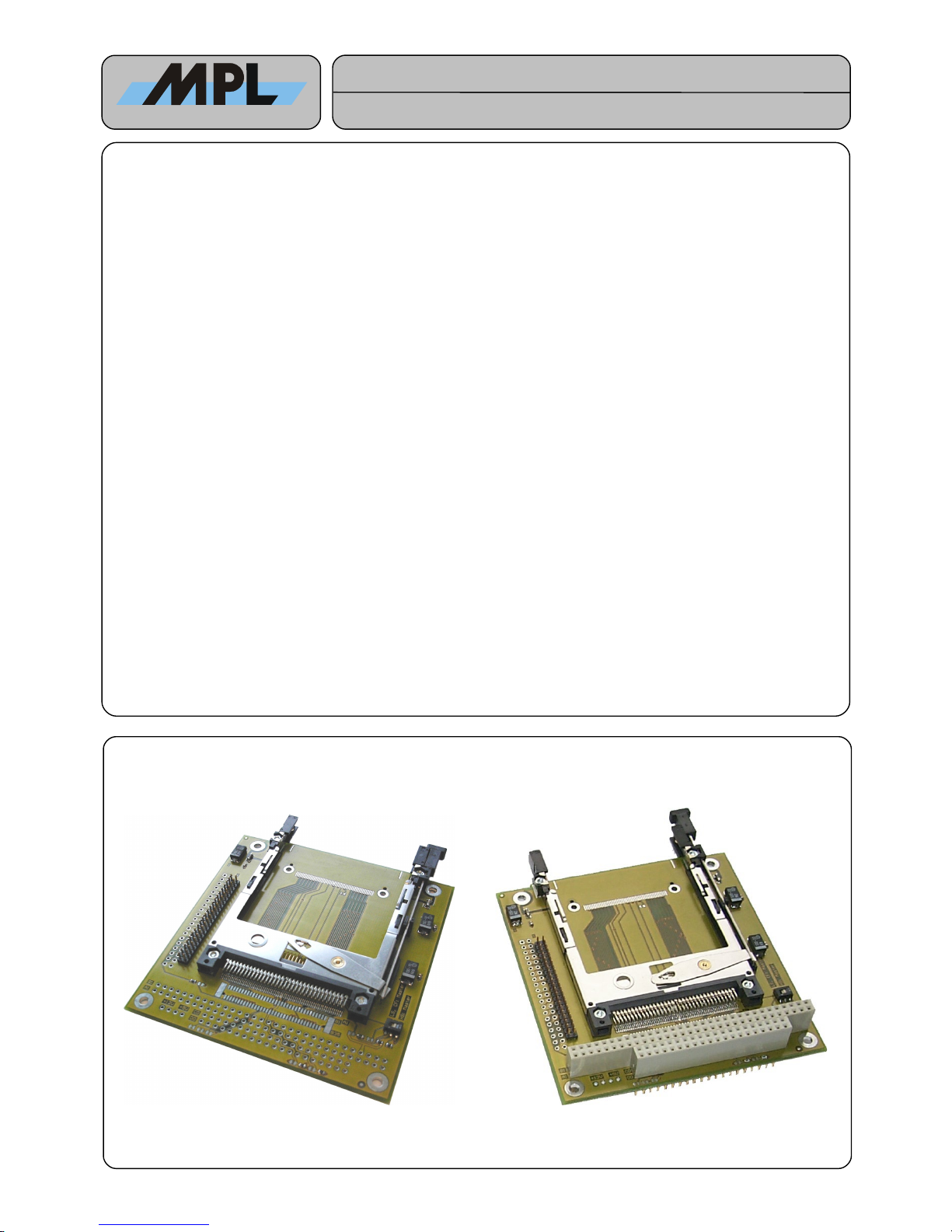
The IDE2PCC is a cost effective and easy to use adapter for connecting PCMCIA PC Cards ATA with true IDE interface
(PC Cards) to the standard IDE port of a single board computer (SBC) from MPL or other manufacturers.
For mechanical fixing in MPL’s PIP family, the IDE2PCC can be connected to the PC/104 slot. The PC Card slot is then
available on the right side of the PIP case. For mounting on top of other SBCs, the mounting holes defined in the PC/104
specification are available.
The IDE signals are connected to the IDE2PCC via a standard 40 or 44 pin IDE cable. The power is distributed either
with the 44 pin IDE cable or through the PC/104 connector.
There are two standard variants of the IDE2PCC available. Others are possible on request:
IDE2PCC-1A44: With PC Card interface, 44 pin IDE connector and PC/104 connector.
(For PIPx / MIPx with the possibility to install an additional PC/104 card on top of it, no 12 V
PC Card support).
IDE2PCC-1N44: With PC Card interface, 44 pin IDE connector without PC/104 connector
(For general use with any kind of SBC with IDE port, no 12 V PC Card support).
At the time of writing of this manual the following MPL products are supported:
• PIP405
• The full MPL PIP-Product Range
• MIP405
• MIP520
Features:
• Easy to use & inexpensive
• PC/104 form factor
• Optional separate power connector
• 44 pin (optional 40 pin) IDE connector
• Master / Slave selection possible
• Optional 2 PC Card Slots (Master & Slave)
• For bigger order quantities several assembly options are available. Please feel free to contact MPL AG
for further information.
2003 by MPL AG
1
High-Tech • Made in Switzerland

MEH-10093-001 Rev. B
IDE2PCC
User Manual
TABLE OF CONTENTS
1. INTRODUCTION............................................................................................................................................................... 3
1.1 ABOUT THIS MANUAL................................................................................................................................................ 3
1.2 SAFETY PRECAUTIONS AND HANDLING................................................................................................................ 3
1.3 ELECTROSTATIC DISCHARGE (ESD) PROTECTION..............................................................................................3
1.4 EQUIPMENT SAFETY................................................................................................................................................. 3
2. GENERAL INFORMATION............................................................................................................................................... 4
2.1 DESCRIPTION............................................................................................................................................................. 4
2.2 SPECIFICATIONS....................................................................................................................................................... 4
3. ASSEMBLY OF THE IDE2PCC........................................................................................................................................5
4. PIN ASSIGNEMENT AND SIGNAL DESCRIPTION......................................................................................................... 6
4.1 44 PIN IDE CONNECTOR (J4).................................................................................................................................... 6
4.2 40 PIN IDE CONNECTOR (J1).................................................................................................................................... 6
4.3 PC/104 CONNECTOR (J2 / J5)................................................................................................................................... 7
4.4 OPTIONAL 4 PIN POWER CONNECTOR (J3)........................................................................................................... 7
5. USE OF THE IDE2PCC.................................................................................................................................................... 8
5.1 SELECTION OF THE NEEDED IDE2PCC.................................................................................................................. 8
5.2 SLIDE SWITCH CONFIGURATION............................................................................................................................. 8
5.3 INSTALLING THE IDE2PCC........................................................................................................................................ 8
5.4 USE OF THE PC CARDS............................................................................................................................................ 8
5.5 BOOT FROM IDE2PCC............................................................................................................................................... 9
6. MECHANICAL DATA...................................................................................................................................................... 10
7. COPYRIGHT, REVISION HISTORY............................................................................................................................... 12
8. DISCLAIMER.................................................................................................................................................................. 12
9. SUPPORT....................................................................................................................................................................... 12
2003 by MPL AG
2
High-Tech • Made in Switzerland

MEH-10093-001 Rev. B
IDE2PCC
User Manual
1. INTRODUCTION
1.1 ABOUT THIS MANUAL
This manual provides all the information necessary to handle and configure the IDE2PCC.
The manual is written for technical personnel responsible for integrating and using the IDE2PCC into their systems.
1.2 SAFETY PRECAUTIONS AND HANDLING
For personal safety and safe operation of the IDE2PCC, follow all safety procedures described here and in other
sections of the manual.
• Remove power from the system before installing (or removing) the IDE2PCC to prevent the possibility of personal
injury (electrical shock) and / or damage to the product.
• Handle the product carefully; i.e. dropping or mishandling the IDE2PCC can cause damage to assemblies and
components.
• Do not expose the equipment to moisture.
NOTE:
There are no user-serviceable components on the IDE2PCC.
1.3 ELECTROSTATIC DISCHARGE (ESD) PROTECTION
Though there are no components on the IDE2PCC that are sensible to electrostatic discharge some precautions were
taken to protect the circuits of the IDE interface connected to the IDE2PCC. The electrostatic charge of the PC Card to
be inserted is shunt to the system ground during insertion via the card rails. The connector pins itself do not have
additional protection!
1.4 EQUIPMENT SAFETY
Great care is taken by MPL that all its products are thoroughly and rigorously tested before leaving the factory to ensure
that they are fully operational and conform to specification. However, no matter how reliable a product, there is always
the remote possibility that a defect may occur. The occurrence of a defect on this device may, under certain conditions,
cause a defect to occur in adjoining and/or connected equipment. It is your responsibility to protect such equipment when
installing this device. MPL accepts no responsibility whatsoever for such defects, however caused.
2003 by MPL AG
3
High-Tech • Made in Switzerland

MEH-10093-001 Rev. B
IDE2PCC
User Manual
2. GENERAL INFORMATION
2.1 DESCRIPTION
The IDE2PCC is a cost effective and easy to use adapter for connecting PCMCIA PC Cards ATA (PC Cards) to the
standard IDE port of a single board computer (SBC) from MPL or other manufacturers.
With IDE2PCC the storage cards are used like IDE hard disks.
They are not hot plug capable in IDE2PCC.
If you require hot plug use the PCCARD of MPL AG.
2.2 SPECIFICATIONS
2.2.1 SUPPORTED CARD TYPES
Only PCMCIA PC Cards ATA with true IDE interface (PC Cards) are supported. These cards are memory cards and
have a true IDE mode and so they can be directly connected to the standard IDE/ATA interface via IDE2PCC. For I/O
cards like MODEM, LAN, .. please use MPL’s PCCARD (www.mpl.ch).
2.2.2 POWER SUPPLY
• IDE2PCC accepts only 5 V PC Cards.
• Care has to be taken with defective storage cards. There are no protection circuits on the IDE2PCC against
increasing current flow. All the current provided by the SBC can flow to the storage card.
2.2.3 OPERATING ENVIRONMENT
• Temperature range: -20° C to +70° C
• Relative humidity: 95% maximum (non condensing)
2.2.4 STORAGE ENVIRONMENT
• Temperature range: -40°C to +85°C
• Relative humidity: 95% maximum (non condensing)
2003 by MPL AG
4
High-Tech • Made in Switzerland
 Loading...