

MPK VisionVent M pro 4751P, 44P, VisionVent M pro 4701P, 4400P, 46P Fitting And Operating Instructions
...Page 1
1
Fitting and Operating Instructions
GB
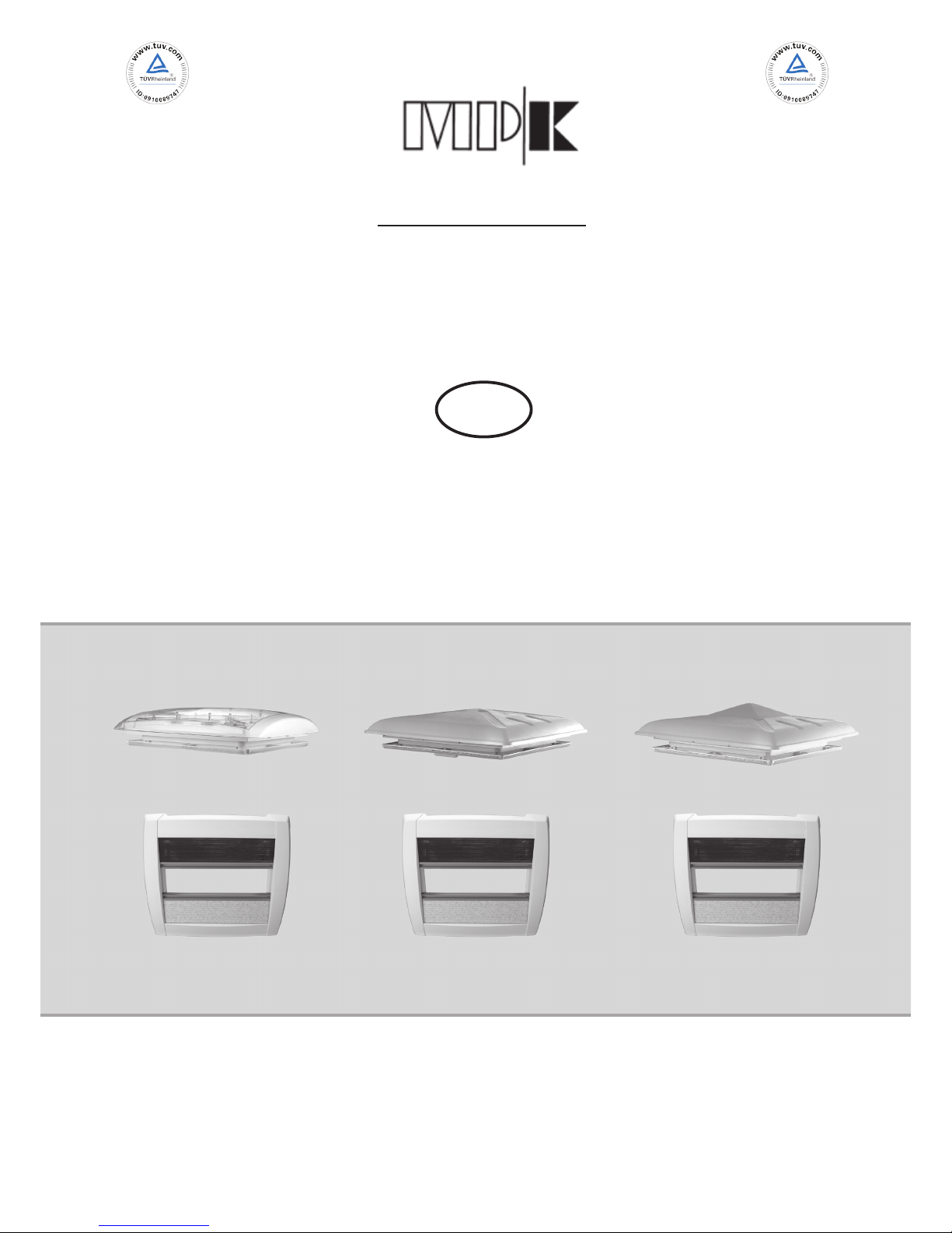
Rooight VisionVent M pro - Model 4751P (4701P)
Special Models 44P/ 4400P, 46P/ 4600P/ 42P
Issue May 2011
Metall- und Plastikverarbeitungs- GmbH & Co. KG Kierspe
Internet: www.mpk-kierspe.de
We reserve the richt to change technical
specications without notice. E&OE
ISO 9001:2008
Cert.-No. 01 100 89747
ISO 14001:2004
Cert.-No. 01 104 069609
Page 2
2
We only recommend installation by authorised dealers.
Please read these instructions carefully before tting and operating the rooflights.
Illustration
1 2
3
4 5
6
7 8
9
standard
screw
hole
plastic
screw hole
Important: We cannot be held responsible for incorrect tting, handling or operation.
Any product faults relating to the production and materials used should be noticed to us via
an authorised dealer immediately.
10 11 12
wrongwrong
wrong
wrong
wrong
Page 3
3
Fitting Instructions
Warning!
Fitting position
Aperture size
Roof thickness
Fitting direction
Fixing screws
- Upper frame
- Inner frame
Sealing
Fitting
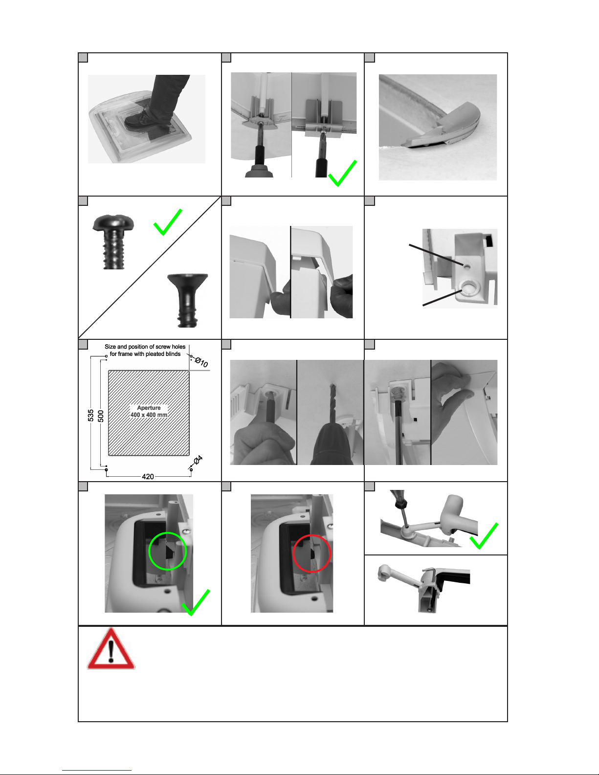
Never stand on the dome of the rooight!
(See picture 1)
Choose a tting position that will not interfere with other roof
mounted components (e.g. roof-racks/antenna’s etc.) and avoid
internally installed electrical cables and furniture, which could
impede the correct operation of the rooight.
The rooight should only be tted to a at roof surface, both in-
ternally and externally.
400x400 mm (see technical data page 5)
Ensure the correct rooight is selected for the roof thickness (for
available size options see technical data page 6).
Rooights must only be tted with the operating handles facing
the front and rear of the vehicle, not across the vehicle.
Pan 3,5 mm/head according to DIN ISO 7049 (DIN 7981)
Screw size - When fully tightened the screw should enter the outer
frame about 10 mm.
The length of the screw for the inner frame max. 10mm.
Do not use countersunk screws as they will damage the rooight
frame (see picture 4).
Use only long term exible sealant, suitable for external use, (not
supplied), and also suitable for the material of the upper frame.
Consult your sealant supplier.
Separate the inner and outer frames and t the outer frame to
the outside of the roof aperture onto a bed of sealant, with the
operating handles facing front and rear of the vehicle.
Place over the screw holes on the inside of the frame, the 8
xing brackets; four in each corner, four in the centre of each
side. Secure with screws (see picture 2). Screws not supplied.
Attention: Do not over-tighten the screws, stop as soon as the
brackets start to distort. (See picture 3).
Max. Torque 0.5 Nm
To t the inner frame, gently pull out the pointed ends of the cover
proles to release them and reveal the xing points.
(See picture 5).
There are two xing holes in each corner of the frame, for two
xing options (See picture 6 - 7).
It is recommended that the inner frame is tted with the blinds to
the side of the vehicle, opposing the operating handles..
Page 4
4
Fitting Instructions
Fitting
Instruction for use
Free-air-ow
Before driving
The four large holes are used to t the frame to the inner lining
panel only, where there is no supporting timber frame, using the
large plastic screws supplied. Offer up the inner frame into the
outer frame and mark the central position of the large holes. Drill
holes for the screws and secure the frame to the roof with the
plastic screws. Tighten by hand, do not over-tighten.
(See pictures 8 - 9)
The four small holes are used to t the frame to the roof when
there is a timber support under the roof lining, using standard
screws (not supplied). Make sure the timber support is large
enough and under the small xing holes. (See picture 7)
Offer up the inner frame into the outer frame. Secure the frame
to the roof by xing the screws directly into the timber support.
Tighten by hand, do not over-tighten.
Attention: Make sure that the outer panel is not damaged by
drilling through (max drill depth 5mm) or using screws that are
too long.
Ret the inner frame covers by locating the securing lugs and
keeping the covers parallel against the roof whilst sliding them
carefully onto the frame, ‘clicking’ back into position, without
distorting.
The rooight can be opened fully by the handles, or in four different directions, so that the dome can be angled against driving
weather conditions.
The ynet and the blind can be operated together or separately.
To open the rooight dome both have to be opened.
When closed there is a free airow through the rooight, which
must be kept free at all times (see technical data page 5-7)
IMPORTANT: All rooights must be locked down before traveling
and both roller blinds locked in the fully open position against the
frame.(See picture 10-11)
Make sure the ynet and the blind are in open position to avoid
damage and noise by airow.
Operation Instruction
Page 5

5
Care Instructions
Technical Data:
Aperture: 400 x 400 mm
Corner radius: 25 mm
Size dome model 42P: 470 x 470 mm
other models: 560 x 560 mm
Height over roof model 42P: 91 mm
model 44P/ 4400P: 117 mm
model 46P/ 4600P: 92 mm
model 4751P (4701P): 96 mm
Free-air-ow: Please refer to model options
Outer frame material: Polypropylene
Dome material model 4751P PMMA/ SAN
Other models: Polypropylene
Product description
- Clear or opaque domes with free airow
- Spring assisted mechanism, can be tipped in 4 directions, with locks
- concealed xing screws
- Inner frame with pleated ynet + blind (optional ynet only)
- ECE R43 Whole Vehicle Type Approved
Model 4400P approved according to TA29
(Please ask for further details.)
Technical Information
The rooight should only be washed by hand, using a sponge
with plenty of clean water to avoid scratching. Caustic detergents
and solvents may attack the plastic and make it brittle or disinte-
grate.
For easier cleaning of the dome it can be removed from the frame
by releasing the four screws holding the handle arms (models from
May 2010, Torx TK10 screws). (See picture 12)
Make sure that only the original screws are used when replacing
the dome and that they enter the thread in the plastic correctly.
Do not over-tighten.
Never remove the screws holding the dome and the handles together (see picture 12). These are secured by a torque screwdriver
and should only be handled by an approved dealers.
To remove the inner frame for cleaning, with the ynet and blind
attached, follow the reverse of the tting instructions; removing
covers and screws.
Cleaning
Page 6

6
Technical Information
Model options:
Model 44 (opaque dome)
white grey beige blind net roof thickness air-ow weight
440VPW-D 440VPG-D -------- X X 24 - 56 mm 95 cm² 3090 g
441VPW-D 441VPG-D -------- X X 42 - 70 mm 95 cm² 3190 g
Model 4400 (clear dome)
white grey beige blind net roof thickness air-ow weight
4400VPW-D 4400VPG-D -------- X X 24 - 56 mm 95 cm² 3090 g
4410VPW-D 4410VPG-D -------- X X 42 - 70 mm 95 cm² 3190 g
Model options:
Model 46 (opaque dome)
white grey beige blind net roof thickness air-ow weight
460VPW-D 460VPG-D -------- X X 24 - 56 mm 150 cm² 3135 g
461VPW-D 461VPG-D -------- X X 42 - 70 mm 150 cm² 3235 g
460VPW-D-3 460VPG-D-3 -------- X X 24 - 56 mm 30 cm² 3135 g
461VPW-D-3 461VPG-D-3 -------- X X 42 - 70 mm 30 cm² 3235 g
Model 4600 (clear dome)
white grey beige blind net roof thickness air-ow weight
4600VPW-D 4600VPG-D -------- X X 24 - 56 mm 150 cm² 3135 g
4610VPW-D 4610VPG-D -------- X X 42 - 70 mm 150 cm² 3235 g
4600VPW-D-3 4600VPG-D-3 -------- X X 24 - 56 mm 30 cm² 3135 g
4610VPW-D-3 4610VPG-D-3 -------- X X 42 - 70 mm 30 cm² 3235 g
Model options:
Model 4751 - clear dome (4701)
white grey beige blind net roof thickness air-ow weight
4751VPW-D 4751VPG-D -------- X X 24 - 56 mm 150 cm² 3645 g
4761VPW-D 4761VPG-D -------- X X 42 - 70 mm 150 cm² 3745 g
Model 42P on request only!
Page 7

7
Spare parts
Colour frame:
No. Spare parts beige
white
grey
Replacement dome, locks
1a Replacement dome model 4751P (4701P)
clear - 150 cm² air-ow --------------- 4751.52VW 4751.52VG
1b Replacement dome model 46P / 4600P
opaque - 150 cm² air-ow --------------- 460.52VW 460.52VG
opaque - 30 cm² air-ow --------------- 460.52VW-3 460.52VG-3
clear -150 cm² air-ow --------------- 4600.52VW 4600.52VG
clear - 30 cm² air-ow --------------- 4600.52VW-3 4600.52VG-3
5
6
4
3
1
2
3
4a
Page 8

8
Colour frame:
No. Spare parts beige
white
grey
Replacement dome, locks
1c Replacement dome model 44P / 4400P
opaque - 95 cm² air-ow --------------- 440.52VW 440.52VG
clear - 95 cm² air-ow --------------- 4400.52VW 4400.52VG
1d Replacement dome model 42P
opaque - 150 cm² air-ow --------------- 420.52VW 420.52VG
opaque - 30 cm² air-ow --------------- 420.52VW-3 420.52VG-3
5 Locks; 1 set supplied in polybag with hanger --------------- 420.99S 420.99S
6 Torx screws for handles --------------- 8000.4 8000.4
Replacement frame, xing parts:
2 Outer frame for mod. 44P - 4751P (4701P)
for roof thickness 24 - 56 mm --------------- 420.21W 420.21G
for roof thickness 42 - 70 mm --------------- 421.21W 421.21G
3 Fixing kit - incl. 4 corner brackets, 4 side brackets --------------- 4750.99D 4750.99D
and 4 plastic screws
4 Inner frame, compl. with ynet/ blind --------------- 4750.22PW 4750.22PG
Inner frame, upgrade kit with xing brackets --------------- 4750.22PW-K 4750.22PG-K
4a Side covers for inner frame --------------- 4750.1W 4750.1G
Spare parts
 Loading...