

Page 1

LinkCom 5 User Manual
LinkCom 5 User Manual
How to configure and use LinkCom 5
D13086-002
June 16
Page 2

LinkCom 5 User Manual
Page 2
Page 3

LinkCom 5 User Manual
Page 3
Content
1 ABOUT MPI TECH ................................................................................................ 6
1.1 Trademarks ................................................................................................ 6
1.2 Contact ...................................................................................................... 6
2 INTRODUCTION .................................................................................................. 7
2.1 Terms and definitions ................................................................................... 7
2.2 Related documentation ................................................................................. 8
2.3 About this document .................................................................................... 9
2.4 Document history ........................................................................................ 9
3 INTRODUCTION TO LINKCOM 5 ........................................................................ 10
3.1 Intention .................................................................................................. 10
3.2 Product features ........................................................................................ 10
3.3 Requirements ............................................................................................ 11
3.3.1 PC system requirements ............................................................................... 11
3.3.2 Printer requirements..................................................................................... 11
3.3.3 Host system requirements ............................................................................. 11
4 FEATURES OF LINKCOM 5 ................................................................................. 13
4.1 Overview of LinkCom 5. .............................................................................. 13
4.2 End to end control ..................................................................................... 13
5 INSTALLATION ................................................................................................. 14
5.1 Installation requirements. ........................................................................... 14
5.2 The LinkCom 5 PrintServer can be hardware connected in 3 different ways: ...... 14
5.2.1 Connection via PRT/LAN ports ........................................................................ 14
5.2.2 Connect a USB printer .................................................................................. 15
5.2.3 Host2Net connection .................................................................................... 15
5.2.4 General connection setup .............................................................................. 16
6 OPERATING LINKCOM 5 .................................................................................... 18
6.1 Using test button to print PrintServer configuration ........................................ 18
6.2 Using test button to reset PrintServer to factory defaults ................................ 18
6.3 Understanding PrintServer LED signalling...................................................... 19
6.4 LED signalling explained ............................................................................. 19
7 CONFIGURING LINKCOM 5 PRINTSERVER ........................................................ 20
7.1 Use of PrintGuide ....................................................................................... 20
7.2 Getting started with PrintGuide .................................................................... 20
7.3 Configuring logical printers ......................................................................... 21
7.4 Configuring AFP/IPDS transform .................................................................. 21
7.4.1 PPD ............................................................................................................ 21
7.4.2 IPDS........................................................................................................... 22
7.4.3 Physical Printer ............................................................................................ 24
7.4.4 Strings........................................................................................................ 26
Page 4

LinkCom 5 User Manual
Page 4
7.4.5 Output driver ............................................................................................... 27
7.5 Configuring AFP/ICDS transform .................................................................. 28
7.5.1 PPD ............................................................................................................ 28
7.5.2 PSS ............................................................................................................ 29
7.5.3 Physical Printer ............................................................................................ 30
7.5.4 Strings........................................................................................................ 32
7.5.5 Output driver ............................................................................................... 32
7.6 Configuring DCA Transform ......................................................................... 33
7.6.1 Telnet Print ................................................................................................. 34
7.6.2 DCA ........................................................................................................... 34
7.6.3 Physical Printer ............................................................................................ 35
7.6.4 Strings........................................................................................................ 37
7.6.5 Output Driver .............................................................................................. 38
7.7 Configuring SCS transform .......................................................................... 39
7.7.1 Telnet Print ................................................................................................. 39
7.7.2 SCS ............................................................................................................ 40
7.7.3 Physical Printer ............................................................................................ 41
7.7.4 Strings........................................................................................................ 43
7.7.5 Output Driver .............................................................................................. 44
7.8 Configuring Transparent TCP/IP Printing ....................................................... 45
7.8.1 T Port ......................................................................................................... 46
7.8.2 Physical Printer ............................................................................................ 47
7.8.3 Strings........................................................................................................ 47
7.8.4 Output Driver .............................................................................................. 47
7.9 Printer templates ....................................................................................... 49
7.10 Internal LinkCom 5 web server .................................................................... 49
7.10.1 Accessing the internal web server .................................................................. 49
7.10.2 Status page with Configuration Page. ............................................................. 50
7.10.3 Advanced Configuration ................................................................................ 50
7.10.4 General ....................................................................................................... 51
7.10.5 Logical Printers ............................................................................................ 51
7.10.6 TCP/IP section ............................................................................................. 53
7.10.7 Password section ......................................................................................... 54
7.10.8 Logout of web server .................................................................................... 54
7.10.9 Restart PrintServer ....................................................................................... 54
7.10.10 Restore Factory Default Configuration. ............................................................ 54
7.10.11 Remember to save changes and restart PrintServer ......................................... 55
8 CONFIGURATION OF HOST SYSTEMS ................................................................ 56
8.1 Setup in mainframe TCP/IP environment ...................................................... 56
8.2 PSF/MVS AFP/IPDS printing ........................................................................ 56
8.2.1 PSF/MVS start-up procedure .......................................................................... 56
8.3 PSS/MVS AFP/ICDS printing ........................................................................ 56
8.3.1 PSS printer profile using TCP/IP attachment .................................................... 57
8.4 PSS/VM AFP printing using TCP/IP ............................................................... 58
8.4.1 Sample PSS VM printer profile definition using TCP/IP ...................................... 58
8.5 Setup in OS/400 TCP/IP environment ........................................................... 58
Page 5

LinkCom 5 User Manual
Page 5
8.6 PSF/400 AFP Printing Using TCP/IP .............................................................. 58
8.7 AS/400 / iSeries Settings for Version 3.7, - 7.x ............................................. 59
8.7.1 Creating the PSF configuration ....................................................................... 59
8.7.2 Creating the Printer Device Description ........................................................... 60
9 SCS/DCA PRINTING USING TN3270E/TN5250E ............................................... 62
9.1 TN3270e setup using OS/390 communication server ...................................... 62
9.1.1 Mainframe TCPIP profile definitions: ............................................................... 62
9.2 TN5250e set-up ......................................................................................... 62
9.2.1 Auto-configuration of devices ........................................................................ 63
9.2.2 Manual Configuration of Devices .................................................................... 63
10 LED SIGNALLING EXPLAINED IN DETAILS ........................................................ 67
11 UPDATING FIRMWARE ...................................................................................... 70
11.1 How to update firmware ............................................................................. 70
11.2 Updating firmware with PrintGuide ............................................................... 70
12 USING PRINTGUIDE TO ADD NEW FEATURES ................................................... 72
12.1 Prerequisites ............................................................................................. 72
12.2 Installing new features ............................................................................... 72
13 ENABLING/DISABLING HIDDEN FEATURES ...................................................... 74
13.1 How to enable/disable options ..................................................................... 74
13.2 Disabling IPv6 and DHCPv6 ......................................................................... 74
13.3 Test button reset feature ............................................................................ 75
14 CLONING PRINTSERVER SETTINGS .................................................................. 76
15 TROUBLESHOOTING ......................................................................................... 78
15.1 Changes to the output printer address are not applied .................................... 78
15.2 LinkCom 5 hangs during a restart ................................................................ 79
15.3 Not able to see options for Matrix printing..................................................... 79
15.4 Not able to see finishing options in PrintGuide ............................................... 80
15.5 DCA Output language keeps returning to Matrix ............................................ 81
16 INDEX ............................................................................................................... 82
Page 6

LinkCom 5 User Manual
Page 6
1 About MPI Tech
The MPI Tech Group is a leading provider of document management and document
output solutions that put the customer in charge. With our software and hardware
solutions we enable customers to create, print, secure, transform, distribute and
archive their information.
Our services run on multiple operating systems making it possible for our
customers to manage all their paper and electronic output through a coherent
software and hardware platform.
The MPI Tech products range from Mainframe and Midrange printing solutions
through Server, Embedded and Stand-alone Hardware based transforms to pure
LAN connectivity. The product range also includes document creation tools and
document management and routing solutions that enables customers to manage
their entire document life cycle from document creation to the documents final
destination whether it is digital or paper.
More information is available at www.mpitech.com
1.1 Trademarks
Company and product names mentioned in this manual are trademarks or
registered trademarks of their respective owners. MPI Tech cannot be held
responsible for any technical or typographical errors and reserves the right to make
changes to products and documentation without prior notification.
1.2 Contact
France
40, rue du Général Malleret Joinville
BP 88 - 94402 Vitry sur Seine Cedex
Phone: +33 (0)1 4573 0940
Fax: +33 (0)1 4680 7071
E-mail: [email protected]
Denmark
United Kingdom
Anchor House, 50 High Stret
Bagshot GU19 5AW
Phone: +44 (0)844 800 9803
Fax: +44 (0)1276 452 379
E-mail: [email protected]
Germany
Bavariastrasse 7a
D-80336 Muenchen
Phone: +49 (0)89 35 4762 20
Fax: +49 (0)89 35 4762 11
E-mail: [email protected]
North America - West Coast
4952 Warner Avenue, Suite 301
Huntington Beach, CA 92649-5506
Phone: +1 (714) 840 8077
Fax: +1 (714) 840 2176
E-mail: [email protected]
North America - East Coast
2001 Jefferson Davis Highway, Suite 306
Arlington, VA 22202
Phone: +1 (703) 418 0680
Fax: +1 (703) 418 0684
E-mail: [email protected]
Page 7
LinkCom 5 User Manual
Page 7
2 Introduction
2.1 Terms and definitions
Transform
A conversion from one protocol into another. E.g. the transform from AFP document
type over IPDS data stream into PostScript.
PrintGuide
The Windows application that is used to discover, monitor and configure MPI Tech
PrintServers including LinkCom 5. PrintGuide is also used to backup, modify, and
restore the PrintServer configuration. Feature enablement and software updates are
also applied using PrintGuide.
PrintServer
A device that connects printers to client computers over a network. LinkCom 5 is a
PrintServer, and besides the above description, it can also connect printers with
host systems (AS400, IBM Mainframe, Unix) as well as offer direct TCP/IP port
9100 print from office computers.
Printer definition files
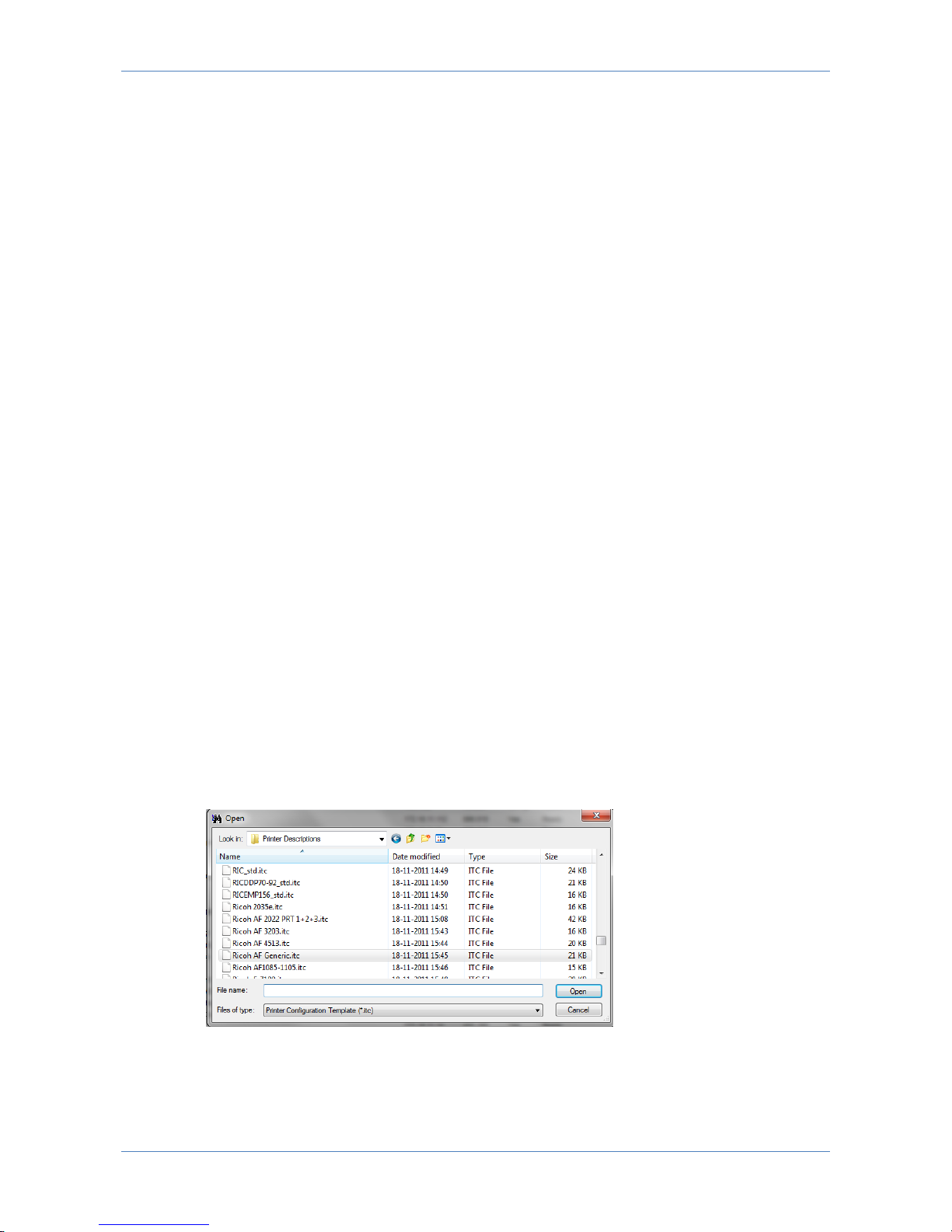
PrintGuide comes preinstalled with predefined printer definition files (*.itc) for
multiple printer models. The files are normally installed in the
“..\MPI Tech\PrintGuide\Printer Descriptions\” subfolder on a computer with
PrintGuide installed. They contain information about trays, duplex-, colourcapabilities, finishing options, paper sizes and printable area.
In order to use a predefined printer definition file with a LinkCom 5 PrintServer, use
PrintGuide to import the desired printer definition file. This is done from the menu
“PrintServer”, “Upload Configuration”. Change “Files of type” to “Printer
Configuration Template” and browse to the location of the ITC files.
Find and select a suitable printer model definition file. It will be applied to the
selected LinkCom 5 PrintServer.
Page 8
LinkCom 5 User Manual
Page 8
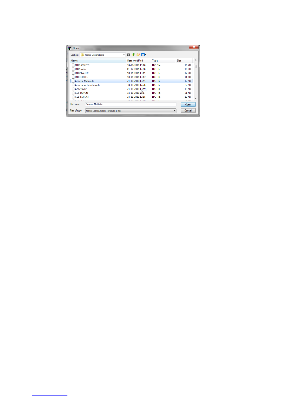
Please note that in order for Matrix options to appear as available options in
PrintGuide it is necessary to first load a matrix printer definition file via PrintGuide.
Firmware
Firmware is the operating system of LinkCom 5. Firmware can be updated using
PrintGuide.
MPI Tech will make firmware updates available to customers with valid
maintenance. Firmware updates can include new features, improvements, error
corrections and other updates.
Host2Net
Host2Net printing is when the PrintServer and the printer are not directly
connected. Instead the PrintServer receives the print data from the host on the LAN
port and targets the output printer using the LAN port sending the output data back
over the network to the destination printer. In this situation, the PrintServer’s PRT
or USB ports are not used.
Maintenance
Maintenance is a yearly fee paid to MPI Tech that allows for the customer to receive
support for their software and hardware solutions purchased from MPI Tech.
The support can be in the form of written help, remote sessions or the like. Error
corrections can also be in the form of new firmware.
2.2 Related documentation
LinkCom 5 Quick Guide, doc. no.D10600
Getting Started with PrintGuide, doc. no. D60364
Host Print Setup Guide, doc. no. D60425
FSL reference, doc. no. D60313
PSS MVS, Product Installation Guide, doc. no. D13052
PSS VM, Installation Guide, doc. no. D13055
EPM Product Guide, doc. no. D13070
Page 9

LinkCom 5 User Manual
Page 9
2.3 About this document
The purpose of this manual is to introduce the LinkCom 5 PrintServer, and help the
user setting up the PrintServer to receive host print data from different host
systems and deliver PCL or PostScript or matrix data (Epson or IBM Proprinter) to a
network or USB printer.
The user is expected to be knowledgeable in how to setup host systems to deliver
data to printers and how to initiate print jobs from the specific host system.
This user guide also contains tips and best practices on the host system side for
various host systems.
2.4 Document history
Major changes in this and previous versions of this manual.
Revision D13086-002
Support for automatic discovering of printer connected via USB or PRT port
Web server added
More detailed configuration page
Support for Matrix printing (Epson and IBM Proprinter emulation)
Revision D13086-001
This is the initial document version.
Page 10

LinkCom 5 User Manual
Page 10
3 Introduction to LinkCom 5
Printing host data on an inexpensive LAN- or USB-based printer used to require
expensive hardware and complicated programming in order to eliminate the
incompatibilities between the two environments. Thanks to the LinkCom 5
PrintServer from MPI Tech, your LAN- or USB-connected printer can receive host
print data using any existing standard TCP/IP host attachments.
LinkCom 5 is capable of receiving host print to support either a USB printer or LAN
connected Printer. Using the built-in transparent network switch, the receiving LAN
based printer can be network connected via the LinkCom 5 PrintServer. This can be
a great benefit eliminating the need for an extra network outlet.
The PrintServer comes with a predefined set of print protocols, print transform and
output device according to the hardware license(s).
High speed print options, full colour support and extra transforms require separate
license.
A new feature for LinkCom 5, is support for Gigabit on the LAN side and that both
IPv6 and IPv4 is now supported.
LinkCom 5 converts host print data to a format that is compatible with standard
office printers. Printers can be connected via LAN or USB. LinkCom 5 delivers realtime conversion that is passed to the printer via the existing LAN or USB
connection.
LinkCom 5 provides conversion of IPDS, ICDS, SCS and DCA host data streams into
PCL5/5c and PostScript languages. Printing to matrix printers using IBM Proprinter
and Epson emulation is also possible with IPDS, SCS and DCA tranforms.
In the basic configuration LinkCom 5 supports one printer session and one ICDS
transform (ICDS to PCL5 or PS). Either one USB printer or one LAN printer. The
LAN printer can either be connected via the LinkCom 5 PRT connector, or reside
elsewhere on the network.
3.1 Intention
This manual describes how to install LinkCom 5, and how to configure the different
features. Please note that some of the features requires additional hardware
licenses.
3.2 Product features
The LinkCom 5 features the following:
TCP/IP session
SCS/DCA with FSL support
IPDS printer emulation (IP40, 4028, 3812, 3816, 4247(matrix))
PCL, PostScript output
Page 11

LinkCom 5 User Manual
Page 11
Provides bi-directional communication between host and selected printer.
(TCP/IP printing. Not USB)
TCP/IP. ver.6 and ver.4 supported.
(Provided that the host/printer also supports IPv6)
Link speed
Gigabit support on the LAN port. 10/100MB support on both LAN and PRT
ports.
3.3 Requirements
This section describes the hardware and host requirements needed for operating
LinkCom 5.
For specification on MPI Tech host-operating system requirements and installation,
please see:
PSS MVS, Product Installation Guide, doc. no. D13052
PSS VM, Installation Guide, doc. no. D13055
EPM MVS Product Guide, document no. D13070
3.3.1 PC system requirements
Hardware:
PC/Server with LAN adapter able to run Windows with the software mentioned
below.
Software:
PrintGuide version S42 065.490 or newer. This version of PrintGuide supports the
LinkCom 5 product, and is used for configuring the product.
3.3.2 Printer requirements
A printer that is connected to LinkCom 5 via a USB cable must be self-powered. It
may not require power via the USB plug exceeding 100mA.
3.3.3 Host system requirements
Mainframe MVS
IBM PSF version 2.1 or higher
PSS/MVS
Either PSS version 6.01 or higher or EPM
ACF/VTAM version 3.1 or higher is required
IBM TCP/IP version 2.1 or higher or Interlink TCP/Access ver.3.1 or higher
Mainframe VM
IBM PSF version 2.1 or higher (only VTAM connection)
Page 12

LinkCom 5 User Manual
Page 12
PSS VM version 6.01 or higher
ACF/VTAM version 3.1 or higher
IBM TCP/IP version 2.1 or higher
Mainframe VSE
PSF/VSE
ACT VTAM
AS/400
OS/400 V3 R1 (incl. PTFs) or higher
PSF/400
Page 13

LinkCom 5 User Manual
Page 13
4 Features of LinkCom 5
LinkCom 5 is delivered preinstalled with features and options according to the
purchased product license. Additional functions, e.g. transforms, full colour, high
speed printing, etc. can be purchased and activated later.
4.1 Overview of LinkCom 5.
LinkCom 5 is a standalone hardware PrintServer.
LinkCom 5 can connect to various types of host and midrange systems and process
host print input to address the needs of heterogeneous print environments. It
provides a method to receive host print data via TCP/IP host attachments, convert
host print data to a format that can be printed on LAN (or USB printers), and
redistribute output to existing LAN print devices. LinkCom 5 provides conversion of
IPDS, ICDS and SCS/DCA host data streams into PCL5/5c or PostScript languages.
Conversion for matrix printing is also possible with IPDS, SCS and DCA host
printing.
LinkCom 5 is licensed to meet the requirements of the actual installation. The
license resides inside the LinkCom 5 PrintServer and enables usage of the
purchased features. Licenses for additional features can be applied and enabled
using PrintGuide.
IPv6 and IPv4 protocols are supported on both incoming and outgoing
communication.
Gigabit speed to and from the PrintServer is supported on the LAN port. 10/100
Mbit is supported on both the LAN and PRT ports.
PrintGuide is used to discover, monitor and configure MPI Tech PrintServers
including the hardware PrintServer LinkCom 5. PrintGuide is used to configure,
backup, alter, and restore configuration settings for PrintServers. LinkCom 5
software updates are installed via PrintGuide.
LinkCom 5 is also equipped with an internal web server for displaying basic
settings. Some configurations possible with PrintGuide, can also be made via the
web server.
4.2 End to end control
Using a direct TCP/IP connection with the printer will allow enhanced end to end
control with LinkCom 5. The LinkCom 5 PrintServer receives status feedback from
the printer and sends the true page count to the AS/400 or mainframe S/390 host
systems. The number of printed pages reported back to the mainframe will always
be the number of printed pages in the printer’s output bin.
Page 14
LinkCom 5 User Manual
Page 14
5 Installation
5.1 Installation requirements.
The LinkCom 5 PrintServer requires that the destination printer either has a fixed IP
address or a fixed pingable host name. There are no such requirements when
printing to printer via a USB port.
A LAN network printer must have one of the following: a fixed IP address, a DHCP
reservation or can be reached using its DNS name. (Example:
printer2.company.org).
5.2 The LinkCom 5 PrintServer can be hardware
connected in 3 different ways:
A network printer connected to the LinkCom 5 PrintServer via the PRT/LAN
ports
A USB printer connected to the LinkCom 5 printer via the USB port
A network printer connected via its own network connection. (Host2Net)
5.2.1 Connection via PRT/LAN ports
Normally the recommended setup for a LAN connected printer is to use the built-in
network switch in the LinkCom 5. This removes the need for an extra network
outlet in the print room.
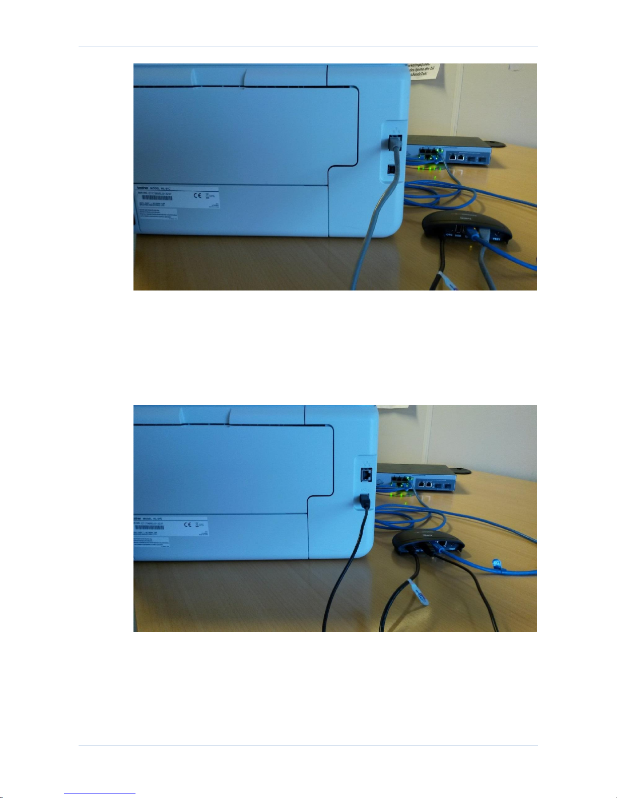
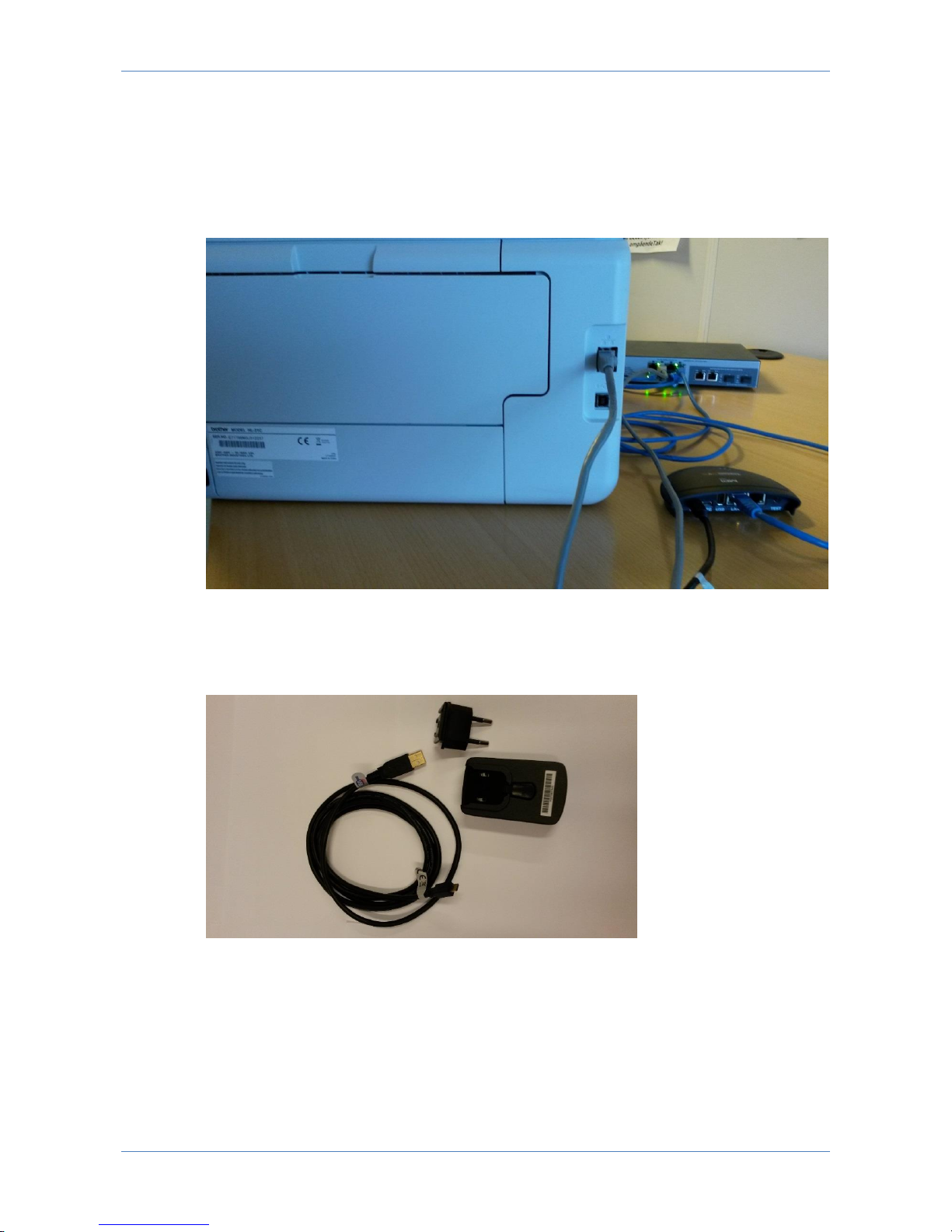
Connect the network printer via the PRT port on the LinkCom 5. The PrintServer is
connected to the network outlet via the LAN port. The setup is illustrated below.
Page 15
LinkCom 5 User Manual
Page 15
5.2.2 Connect a USB printer
A USB printer can be LAN connected via the LinkCom 5 PrintServer.
Connect the LinkCom 5 PrintServer to the network via the LAN port, and connect a
USB cable (USB-A USB-B cable) between the PrintServer and the printer. Plug
the normal USB-A connector into the PrintServer’s USB port, and the USB-B
connector into the USB port on the printer.
5.2.3 Host2Net connection
Host2Net connection is the recommended setup when:
The network printer and the LinkCom PrintServer are located too far from each
other to be directly connected, or
Page 16
LinkCom 5 User Manual
Page 16
local network policies do not allow two network devices to share the same
network connection.
The solution is to connect the LinkCom 5 PrintServer to the network using the LAN
port, and connect the network printer directly to the network. The LinkCom 5 can
be configured to transmit print jobs from the PrintServer to the network printer
over the network.
5.2.4 General connection setup
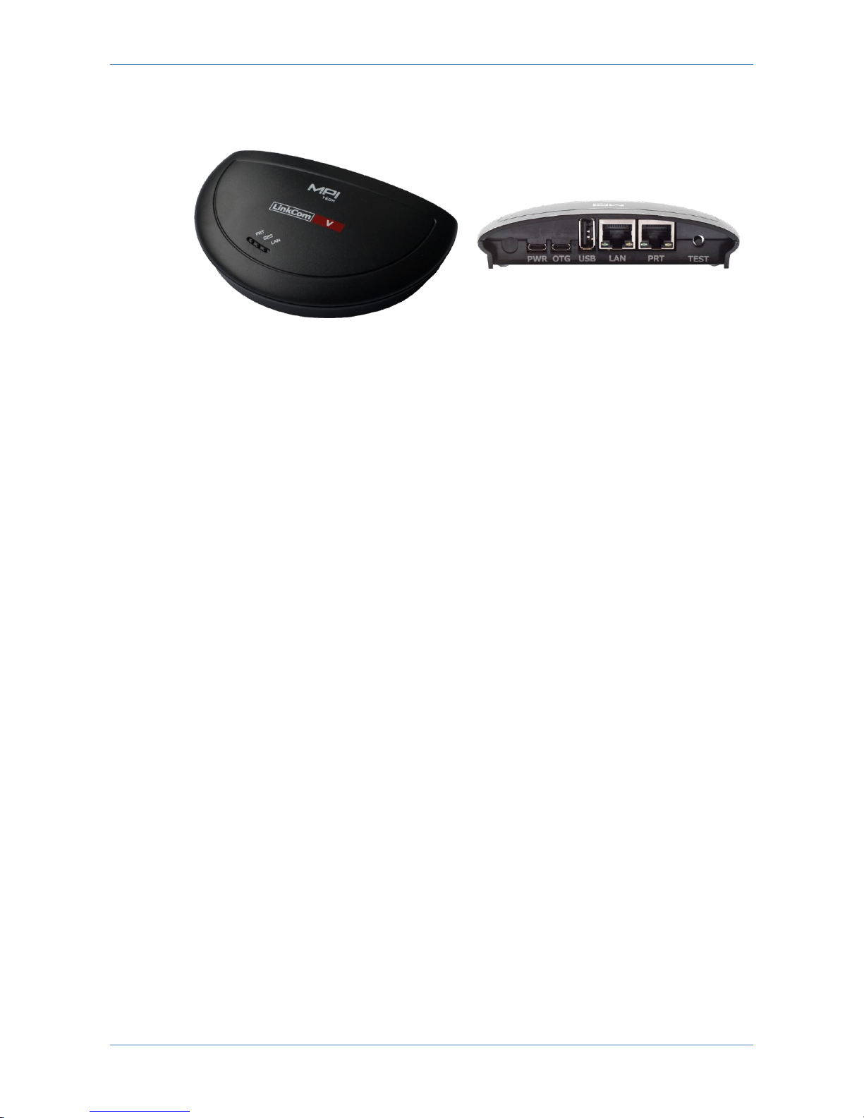
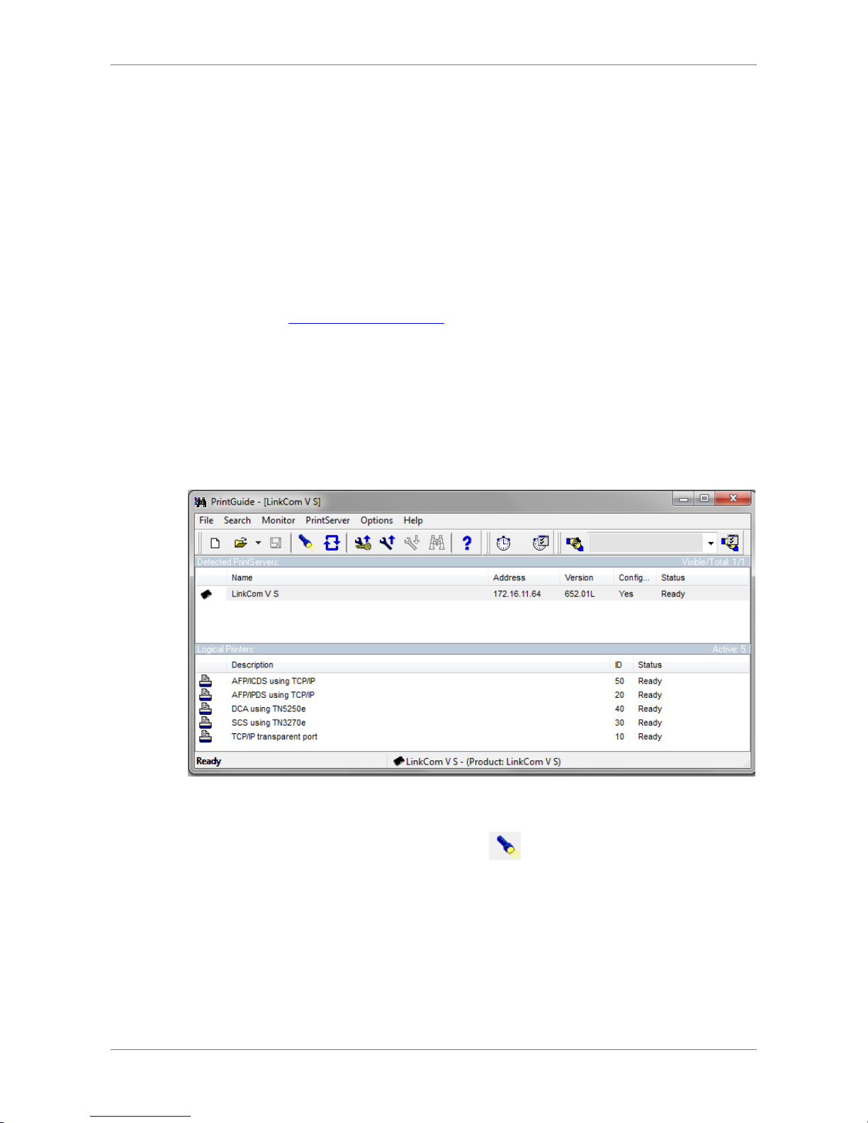
Use the delivered 5V 1A power adapter, regional power plug, and USB-A Micro
USB cable in order to power up the LinkCom 5 PrintServer.
Slide in the regional power plug into the 5V 1A power adapter
Insert the USB-A part of the power USB cable into the 5V 1A power adapter.
Insert the micro USB part of the power USB cable into the PWR socket on the
LinkCom 5 PrintServer. Make sure it is oriented correctly.
Power on the printer
Power up the LinkCom 5.
Page 17

LinkCom 5 User Manual
Page 17
The green LED’s on the LinkCom 5 PrintServer front will blink during the power up
and self-test cycle. A successful power up sequence will end with the LAN led being
constantly lit (indicating that network configuration was successful).
When the LinkCom 5 has successfully completed the power up process it is ready to
be configured using PrintGuide. Refer to section 7 Configuring LinkCom 5
PrintServer for more information about setting up the PrintServer with PrintGuide.
Consult sections 6.4 LED signalling explained, 10 LED signalling explained in details
and 15.2 LinkCom 5 hangs during a restart for help if the PrintServer fail during the
start-up process.
Page 18

LinkCom 5 User Manual
Page 18
6 Operating LinkCom 5
Most setup and management of LinkCom 5 PrintServers is handled through
PrintGuide. Some actions are performed directly on the PrintServer. A built-in web
server offers some configuration options.
6.1 Using test button to print PrintServer
configuration
The test button is located on the rear side of the PrintServer. Pressing the test
button shortly once, will cause the PrintServer to print a basic PrintServer
configuration page on the connected printer. The “PRT” LED will blink one time.
The configuration page contains information about the PrintServer; LinkCom
product name, firmware version, HW/MAC address, IPv6 and IPv4 address
assignment (if relevant), features installed (including transforms, colour support
and resident fonts).
Please note that the printer must be defined in PrintGuide before a configuration
page can be printed. The destination printer must support ASCII text format. If,
however, a USB printer is connected directly to the LinkCom 5 PrintServer via the
USB port the configuration page will be printed on the USB printer thereby
overruling any PrintGuide configuration.
In the situation where the LinkCom 5 PrintServer has not been configured or has
been reset to factory defaults:
If a USB Printer is connected via the LinkCom USB port the configuration page
is printed here.
If a network printer is connected directly to the LinkCom PRT port the
configuration page is printed here.
A detected USB printer will take precedence over a detected network printer when
printing the configuration page. (Please note that directly network or USB printers
are only detected by LinkCom 5 during power up, so a LinkCom 5 power recycle
might be needed)
This makes it easier for a technician not having access to the customers DHCP
server, verifying the setup.
6.2 Using test button to reset PrintServer to
factory defaults
By pressing the test button and holding it pressed between 8 to 60 seconds will
initiate a PrintServer reset to factory defaults routine. After an automatic restart,
the PrintServer will be restored to default settings this includes TCP/IP settings will
default to DHCP assigned IP address. An eventual set device password will not be
cleared.
Page 19

LinkCom 5 User Manual
Page 19
6.3 Understanding PrintServer LED signalling
The PrintServer is equipped with 3 LEDs labelled "PRT", "SES", LAN" for status
signalling.
PRT LED signals print data being sent to or from the designated printer
SES LED signals incoming data from host
LAN LED signals network activity
Each LED can have 4 types of status:
LED is off
LED is constantly lit
LED flashes slowly (approx. 50 times per minute)
LED flashes fast (approx. 100 times per minute)
6.4 LED signalling explained
Right after power up all three front LED’s are off, but shortly after the LAN LED will
start to flash. When the start-up procedure has been completed, the LAN LED
should be lit constantly. The PRT and SES LED may flash shortly from time to time.
For a full list of LED signalling, please see section 10 LED signalling explained in
details“.
Page 20
LinkCom 5 User Manual
Page 20
7 Configuring LinkCom 5 PrintServer
7.1 Use of PrintGuide
All configuration of the PrintServer involves the use of PrintGuide. Please ensure
that you have downloaded the latest version of PrintGuide from
https://www.mpitech.com/ under “Support”, “Software downloads”. The version of
PrintGuide must be PrintGuide version S42 065.490 or newer.
Some configurations can also be made by making changes via the built-in web
server. More about this in section 7.10
Please contact [email protected] if you are not able to get a copy of the
PrintGuide Software version. Make sure to include the LinkCom 5 PrintServer’s MAC
address and Serial number in the e-mail.
For a full introduction to the PrintGuide application, please consult the document
“Getting started with PrintGuide” that is bundled with the software download.
7.2 Getting started with PrintGuide
Install PrintGuide and start the application.
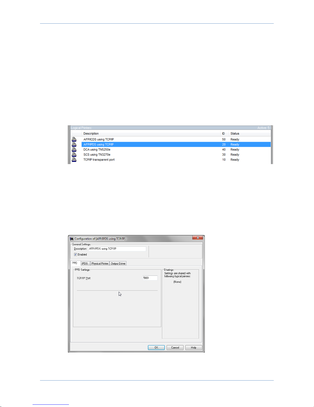
On start-up PrintGuide will scan the network and search for any MPI Tech device
(default setting).
To request a forced network scan, press the icon.
In the default view, PrintGuide displays the PrintServer name, currently assigned IP
address, firmware version (if the PrintServer has been configured), and the general
status.
The list of logical printers displays the available number logical printers/transforms
according to the purchased license.
Page 21
LinkCom 5 User Manual
Page 21
7.3 Configuring logical printers
The PrintServer comes preloaded with the logical printers/transforms that have
been purchased with the PrintServer. All that has to be done, is to configure the
logical printer/transform that is required.
It is possible to configure IPDS, ICDS, DCA, SCS and TCP/IP port 9100 print,
however, the PrintServer can only serve one printer session at a time. E.g. if a host
system is printing AFP over IPDS through the PrintServer a simultaneous DCA print
job must wait for the IPDS job to complete before it can be processed.
7.4 Configuring AFP/IPDS transform
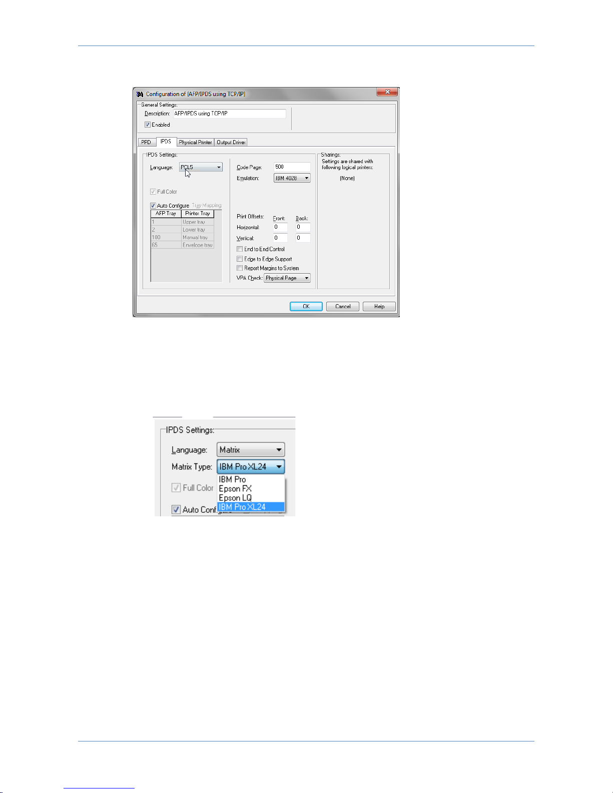
In PrintGuide, select and double-click the AFP/IPDS logical printer
This opens the configuration options:
7.4.1 PPD
The TCP/IP port number is default 5001. But can have any number between 100
and 32000
This is the port number the host system has to target in order to hit the IPDS
transform.
Page 22
LinkCom 5 User Manual
Page 22
7.4.2 IPDS
Language (Output data stream)
Select PCL5 ,PostScript or Matrix*
*) Matrix will only appear as an option, if the logical printer was created based
on a Generic Matrix printer template. (See section 2.1 regarding loading Printer
definition files.)
If Matrix is selected a list of matrix options becomes selectable:
Select between Matrix printer type: IBM Pro, IBM Pro XL 24, Epson FX, Epson
LQ.
Remember to alter your Matrix printer accordingly in case it supports multiple
matrix printer languages.
Code Page
Select the value as required. Default is 500 (Multinational). Value has to match
corresponding value on the host system.
Emulation
Define the IBM emulation which is reported to the IBM host system.
Select the value as required: IBM 3812, IBM 3816, IBM 4028, IBM IP40, IBM 4247*
(IBM 4247 will only appear in the list if the logical printer was created based on a
Page 23

LinkCom 5 User Manual
Page 23
Generic Matrix printer template, and will be the only allowed choice if Matrix is
selected as output data language.)
Full Colour
Available with PostScript output and IBM IP40 emulation (requires a separate
license).
Print Offsets
Is used to adjust the output on the page. Print Offsets will move the entire printed
image on the page. Valid range is -999 to 999 using in units of 1/300 inch. I.e. a
value of 300 will create and offset of 1 inch or approximately. 2.54 cm. Decimals
are not allowed.
Offsets are always calculated using a portrait page, even if the print is landscape.
Examples: Horizontal 150: ½ inch moving to the right (→)
Horizontal -100: 1/3 inch to the left (←)
Vertical 30: 1/10 inch down (↓)
Vertical -60: 1/5 inch up (↑)
AFP Tray Mapping
Is by default set to ‘Auto Configuration’. The available trays are automatically
imported from the trays defined in the Physical Printer definitions. Trays may be remapped by disabling the ‘Auto Configuration’ and click on the tray name and select
the required tray from the list. Only the tray type can be remapped.
End to end control
When checked it causes the PrintServer to receive information from the output
printer about the exact number of printed sheets. This information is sent back to
the host system according to host setup.
Edge to Edge Support
When checked it will inform the host that the output printer supports edge to edge
print (even if the printer is not actually capable of this).
When used with Postscript print, the PrintServer will (if needed) scale down the
print to ensure print data is within the allowed printable area.
When used with PCL print data that is outside the allowed printable area might be
printed outside the actual paper. So use this option with consideration.
Report margins to system
When ticked it will use the margins according to the printer definition, and report
information about the allowed printable areal inside the margins back to the host.
If the option is unchecked, the host will be get the measures of the printable area
of the emulated IBM printer.
Page 24
LinkCom 5 User Manual
Page 24
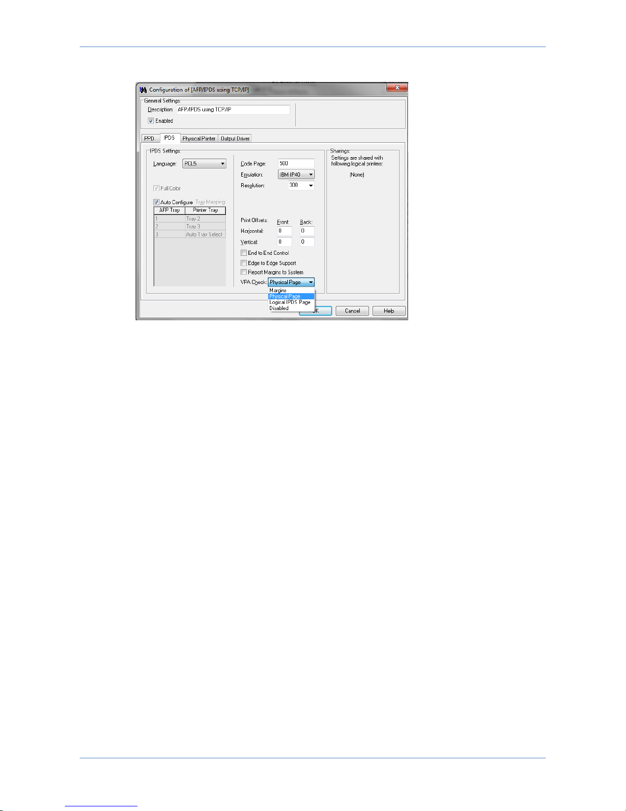
VPA Check - Valid printable area.
This defines what controls the valid printable area reported to the host. An
exception notification is reported back to the host if print data seems to fall outside
the set VPA check option. (Depending on host setup, exception reporting may be
suppressed)
VPA Check Options are:
Margins
Physical Page
Local IPDS Page
Disabled (no notification is sent to the host)
While testing e.g. a new print job it is advisable to use the VPA Check option, in
order to get any errors reported to the host, so that these errors can get corrected.
When printing a known print job (size, format etc.) it is advisable to disable VPA
Check in order to improve performance.
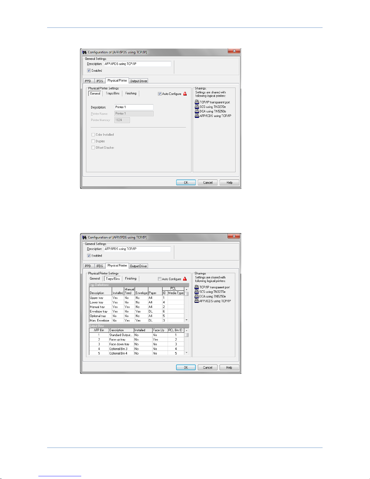
7.4.3 Physical Printer
These parameters are predefined when selecting the Printer Template (see 7.9
Printer templates). The Printer Template defines the target printer in the basic
version. Before any additional options installed in the printer can be accessed,
these must be enabled or defined via the below panels.
If checked ‘Auto Configure’ will attempt to retrieve information about Trays/Bins
paper format etc. directly from the printer. After selecting this option, save the
changes and restart the PrintServer restarted, to collect the information during the
PrintServer start up. Enabling ‘Auto Configure’ disables manual configuration.
Page 25
LinkCom 5 User Manual
Page 25
General printer parameters
General Printer parameters describe the basic printer options: Description and
Printer name and printer memory. Colour, Duplex and Offset capabilities can be
enabled if supported by the printer.
Trays/Bins
Trays/Bins describe and configure the input trays and output bins of the target
printer. Please refer to the printer’s technical manual for configuration of
PCL/PostScript ID’s.
Page 26
LinkCom 5 User Manual
Page 26
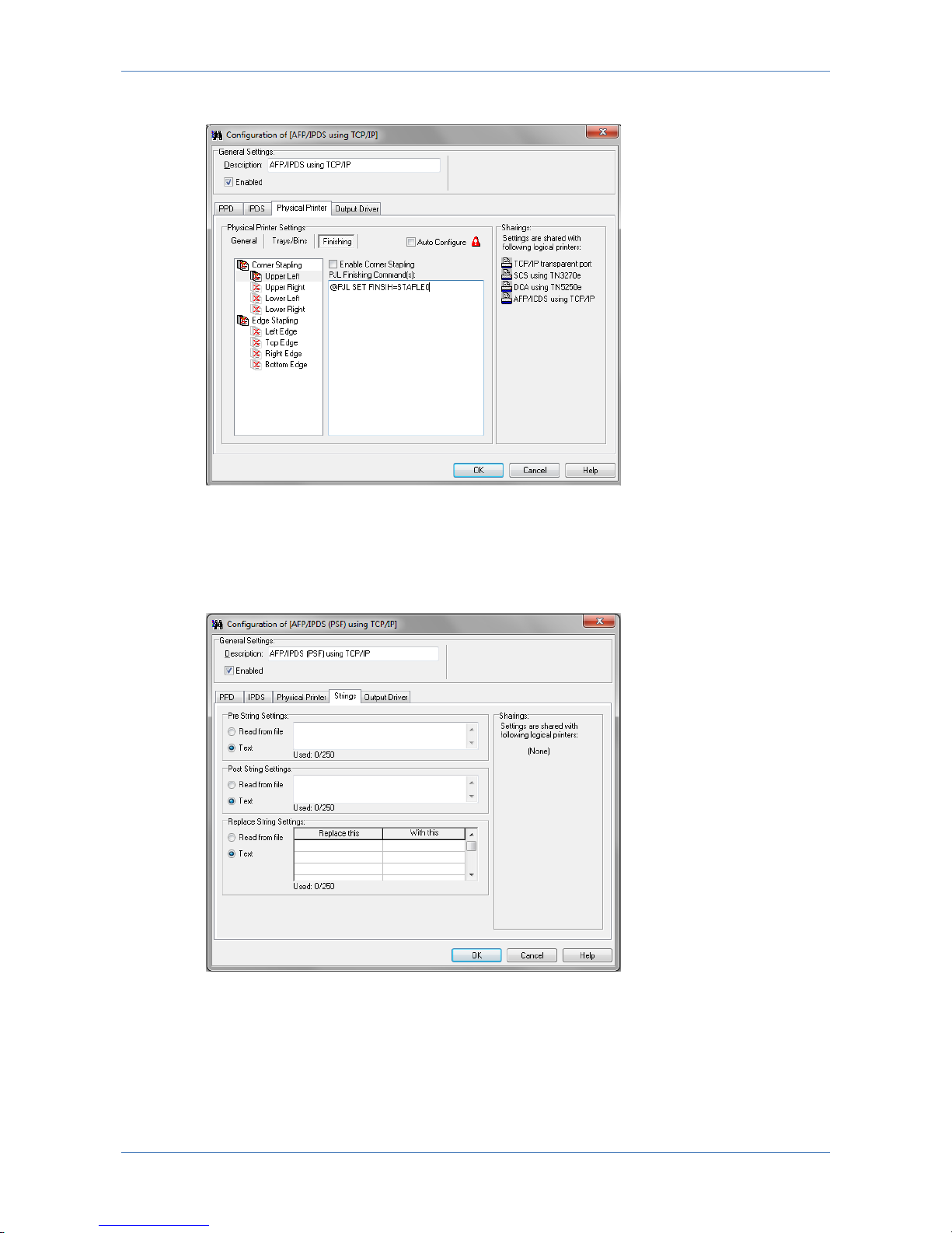
Finishing
Finishing define the stapling options and is configurable if the Printer Template
contains a field for Finishing. Enable stapling for the actual option and consult the
printer’s technical manual for the PJL command to use.
7.4.4 Strings
Strings are used to send data to the printer before the job (Pre String Settings),
after the job (Post String Settings) or can be used to replace data send to the
printer (Replace String Settings). Strings can either be typed in directly, or
imported via a file.
Page 27
LinkCom 5 User Manual
Page 27
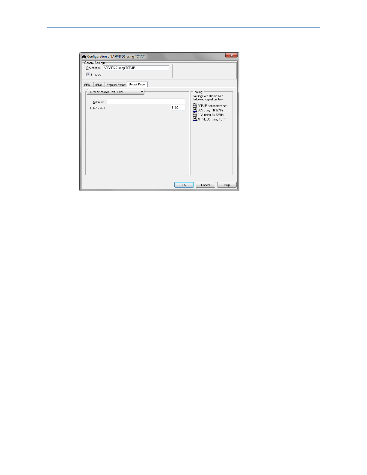
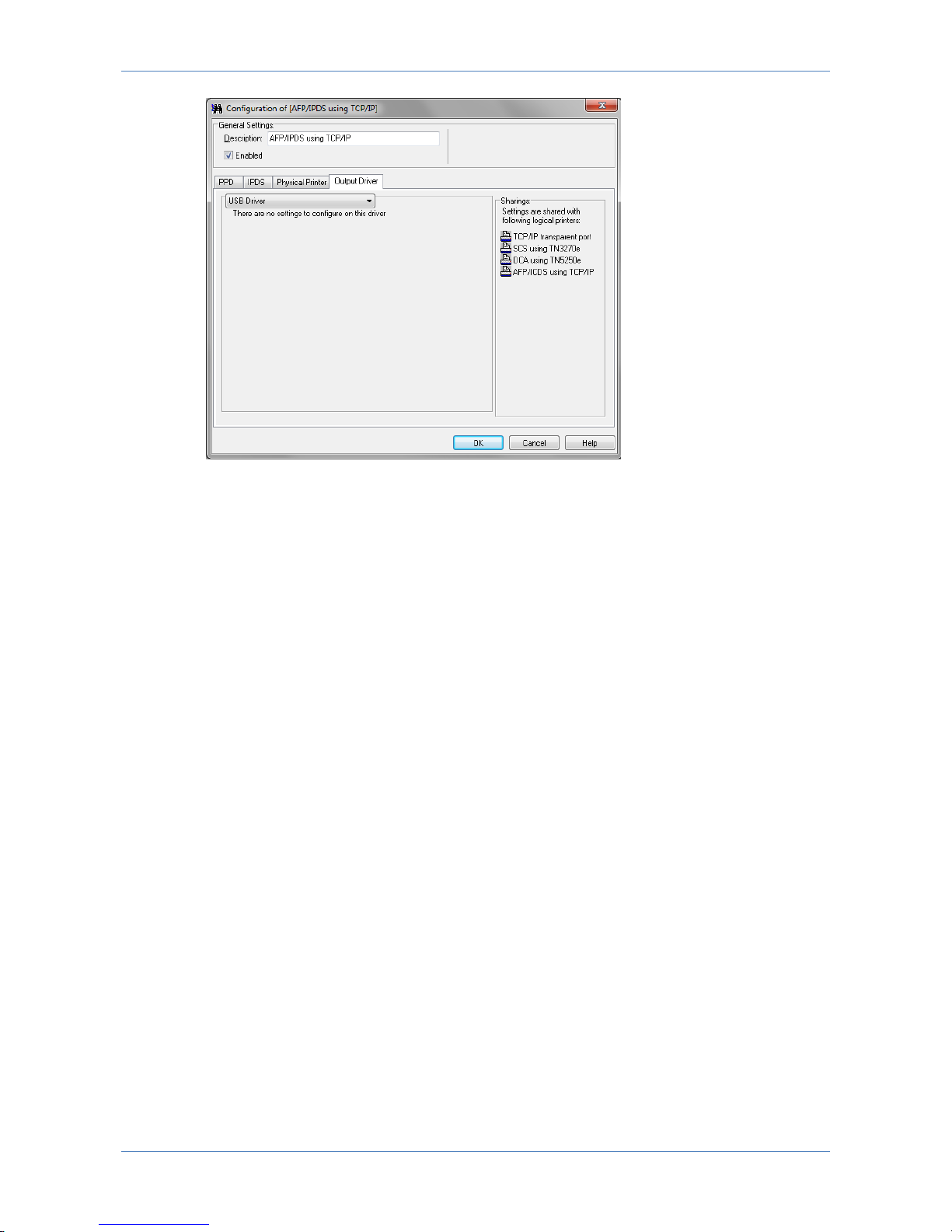
7.4.5 Output driver
Output data from LinkCom 5 can be handled in various ways. Using the default
setup, the data is send to a network printer. “TCP/IP Network port driver”. The IP
Address input field is a text field. Printers can be addressed using IPv4 addresses,
IPv6 addresses or DNS host names.
Example:
172.16.6.148
fe80::d2ff:50ff:fe8c:5ef8/64
printer2.company.org
The selected TCP/IP port (default is 9100) must be a RAW port type, and supported
by the printer.
Page 28
LinkCom 5 User Manual
Page 28
The output printer can also be a USB printer, in which case the PrintServer has to
be directly connected with the USB printer using a USB cable.
7.5 Configuring AFP/ICDS transform
The ICDS transform can be relevant when printing from IBM Mainframe 3270
architecture where the MPI Mainframe products PSS or EPM handles print, as only
those 2 software products can create ICDS data streams.
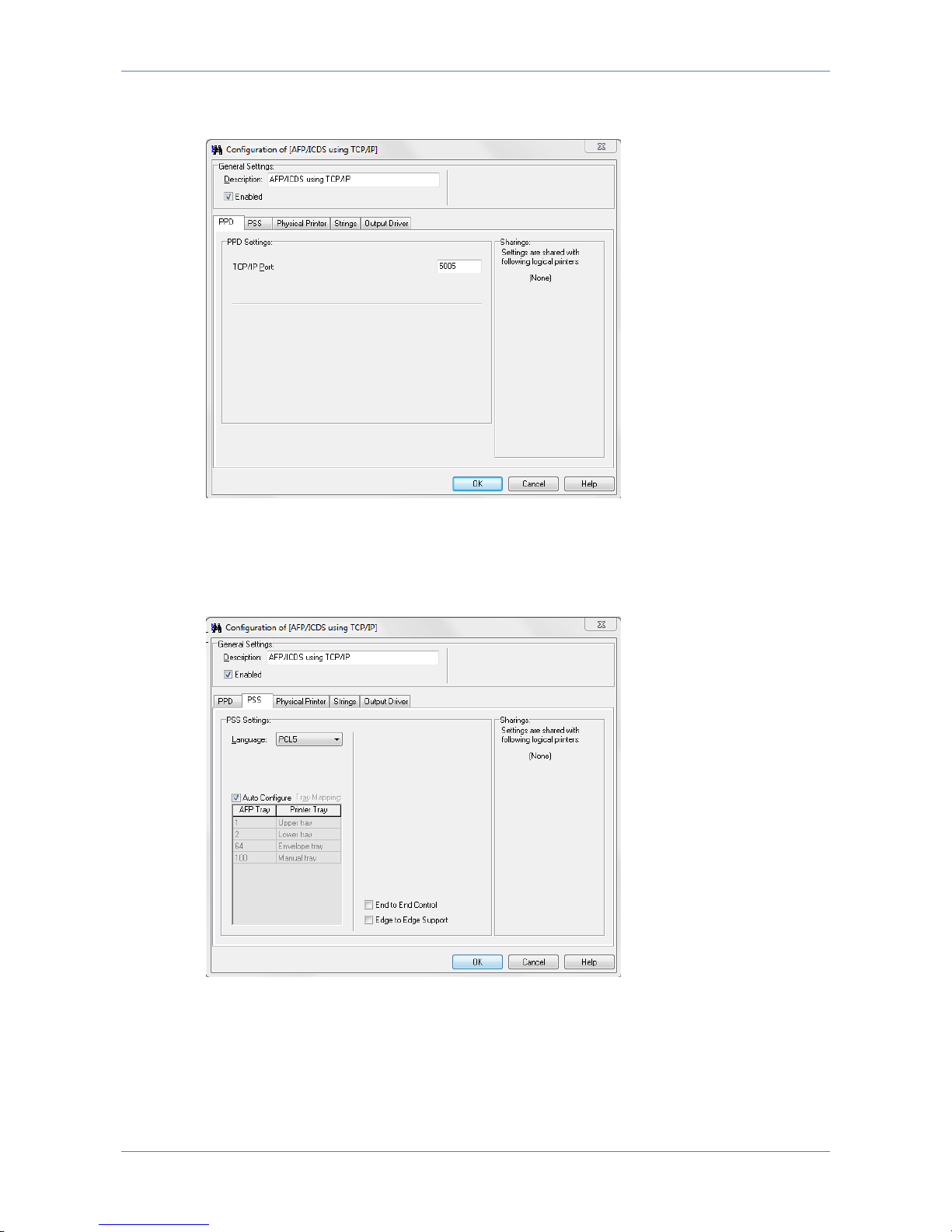
7.5.1 PPD
The TCP/IP port number is default 5005. But can have any number between 100
and 32000.
Page 29
LinkCom 5 User Manual
Page 29
This is the port number the host system has to target in order to hit the ICDS
transform.
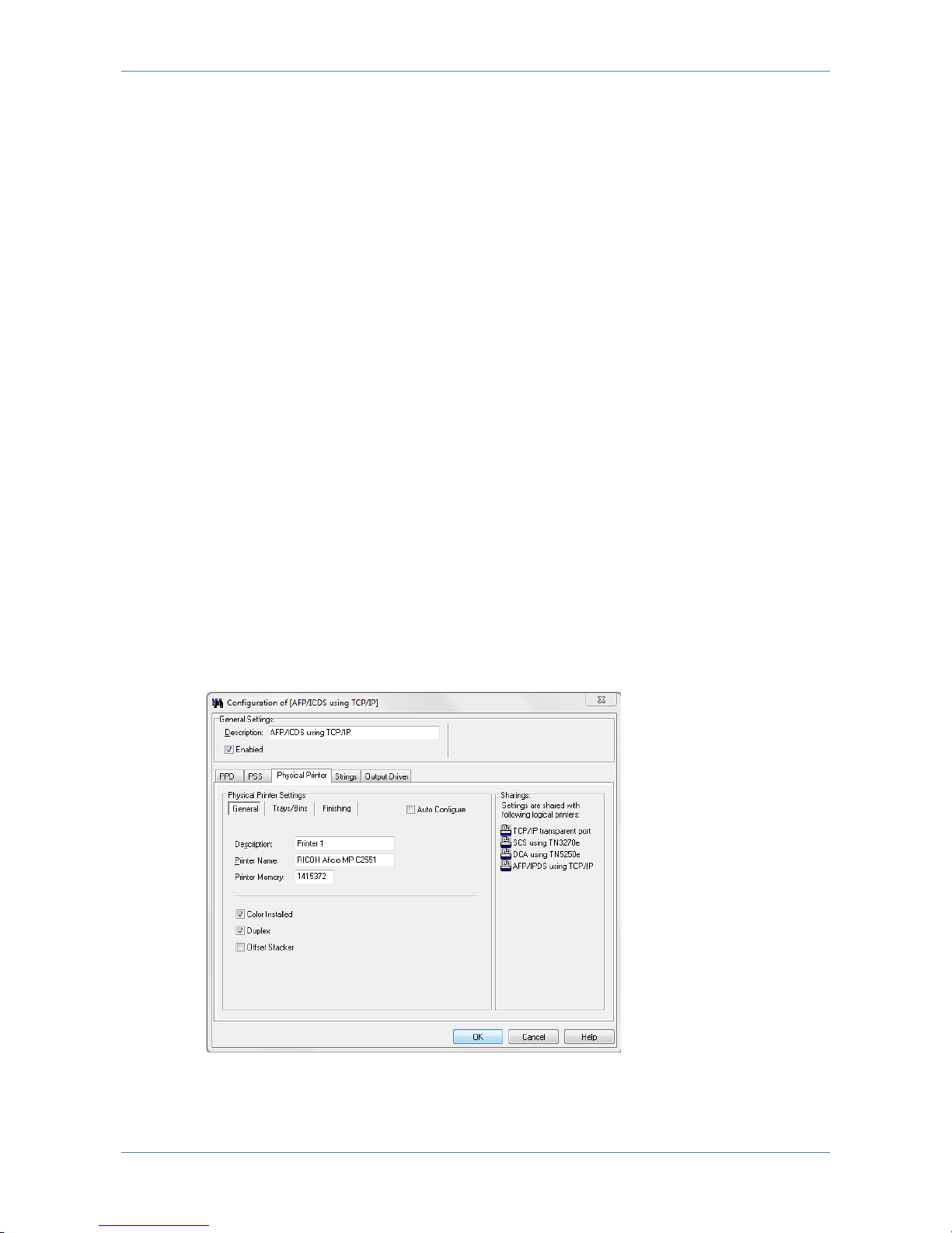
7.5.2 PSS
Language (Output data stream)
Select: PCL5 or PostScript
AFP Tray Mapping
AFP tray mapping is by default set to ‘Auto Configuration’. The available trays are
automatically imported from the trays defined in the Physcial Printer definitions.
Trays can be re-mapped by disabling the ‘Auto Configuration’ and click on the tray
Page 30
LinkCom 5 User Manual
Page 30
name and select the required tray from the list. Only the tray type can be
remapped.
End to end control
When checked it causes the PrintServer to receive information from the output
printer about the exact number of printed sheets. This information is sent back to
the host system according to host setup.
Edge to Edge Support
When checked it informs the host that the output printer supports print from edge
to edge (even if the printer is not capable of this).
When used with PostScript print the PrintServer will (if needed) scale down the
print to ensure print data is within allowed printable area.
When used with PCL print data that is outside the allowed printable area may be
printed outside the actual paper. So use this option with consideration.
7.5.3 Physical Printer
These parameters are predefined when selecting the Printer Template (see 7.9
Printer templates). The Printer Template defines the target printer in the basic
version. These must be enabled or defined via the below panels before any
additional options installed in the printer can be accessed.
When ‘Auto Configure’ is checked it will attempt to retrieve information about
Trays/Bins paper format etc. directly from the printer. After selecting this option,
save the changes and restart the PrintServer to collect information during
PrintServer start up. Enabling ‘Auto Configure’ disables manual configuration.
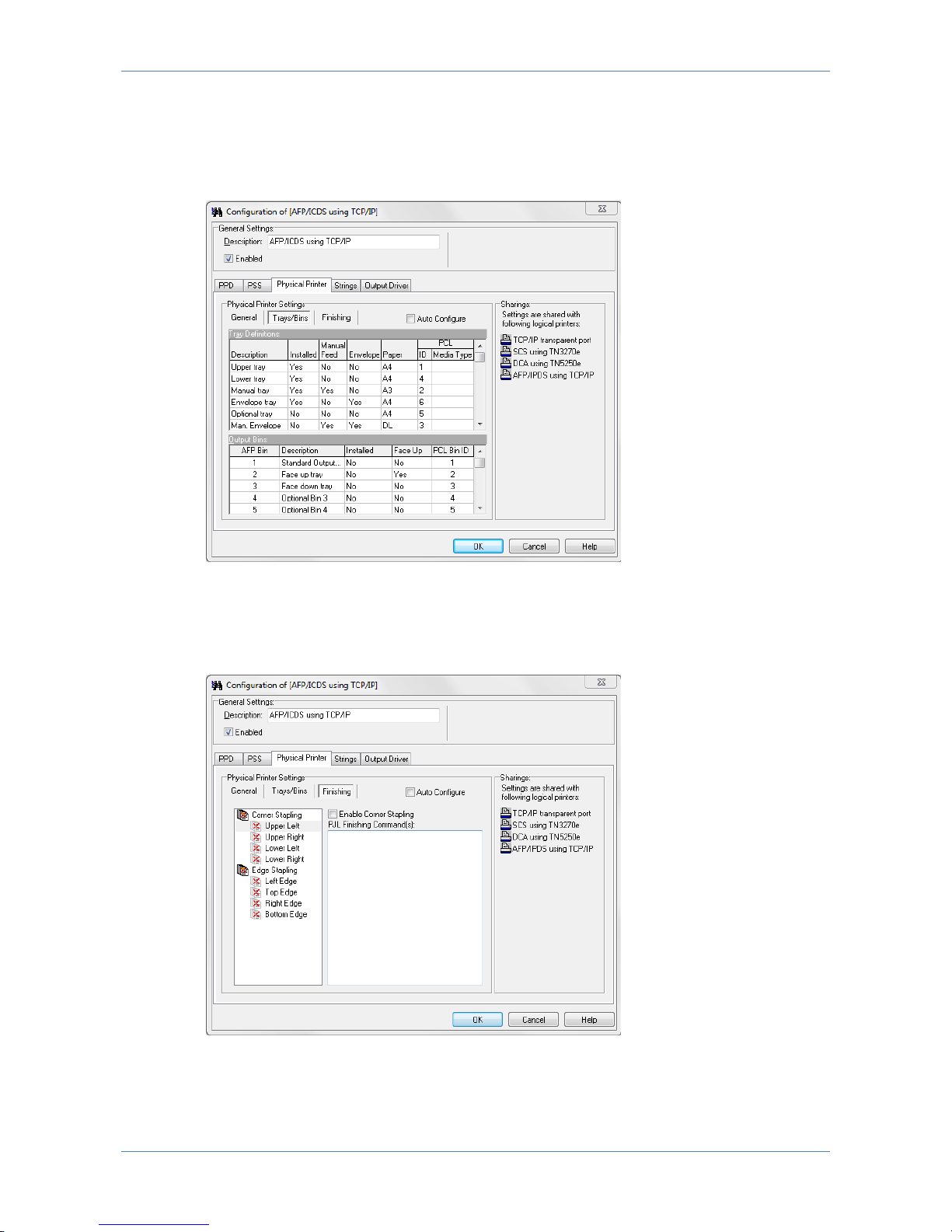
General Printer Parameters
Page 31
LinkCom 5 User Manual
Page 31
General Printer parameters describe the basic options of the printer: Description
and Printer name and printer memory. Colour, Duplex and Offset capabilities may
be enabled if supported by the printer.
Trays/Bins
Trays/Bins describe and configure the input trays and output bins of the target
printer. Please refer to the printer’s technical manual for configuration of
PCL/PostScript ID’s.
Finishing
Finishing define the stapling option and is configurable if the Printer Template
contain a field for Finishing. Enable stapling for the actual option and consult the
printer’s technical manual for the PJL command to use
Page 32
LinkCom 5 User Manual
Page 32
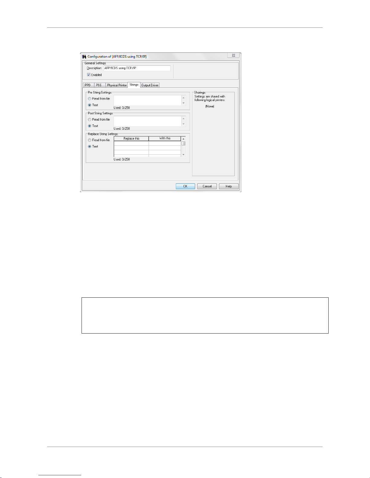
7.5.4 Strings
Strings may be used to send data to the printer before the job (Pre String
Settings), after the job (Post String Settings) or can be used to replace data send
to the printer (Replace String Settings). Strings can either be typed in directly, or
imported via a file.
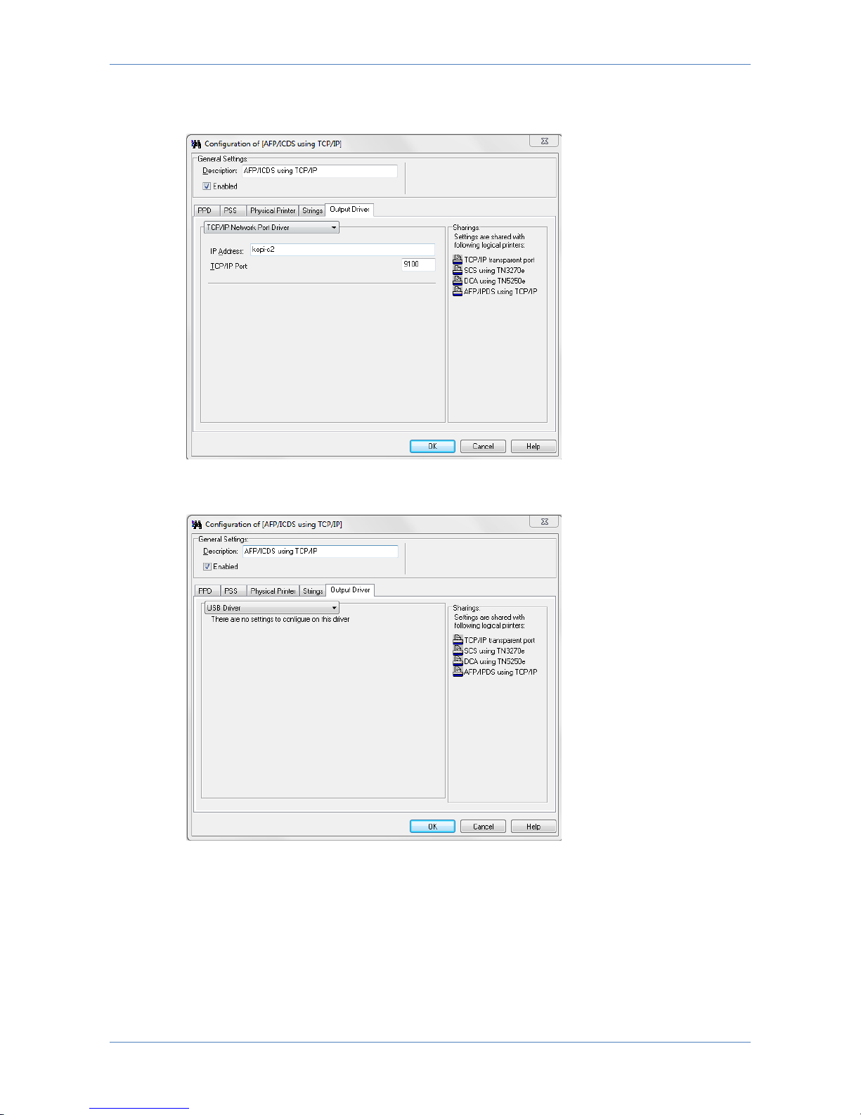
7.5.5 Output driver
Output data from LinkCom 5 can be handled in various ways. Using the default
setup, the data is send to a network printer. “TCP/IP Network port driver”. The IP
Address input field is a text field, so the printer can be addressed using an IPv4
address, an IPv6 address or a DNS host name.
Example:
172.16.6.148
fe80::d2ff:50ff:fe8c:5ef8/64
printer2.company.org
Page 33
LinkCom 5 User Manual
Page 33
The selected TCP/IP port (default is 9100) must be a RAW port type, and supported
by the printer.
The output printer can also be a USB printer, in which case the PrintServer has to
be directly connected with the USB printer using a USB cable.
7.6 Configuring DCA Transform
DCA transform is relevant for AS400 non-graphic text only print. The benefit of
setting up DCA print with PrintGuide, is that once the AS400 host system IP
address and intended DCA printer queue name have been entered, the LinkCom 5
PrintServer will automatically create and configure the DCA printer at the AS400
host. This gives less host system setup compared to e.g. an IPDS printer setup.
Page 34
LinkCom 5 User Manual
Page 34
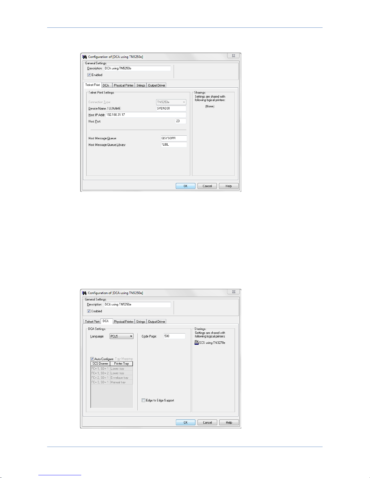
7.6.1 Telnet Print
Device Name / LUNAME
Fill in the Device name you would like to use. This name will automatically be
created as a printer name on your AS400 host. It has to be a unique name and can
have up to 10 characters.
Host IP Address
This is the IP address of the AS400 host system.
Host Port number is 23 and is a predefined host port
7.6.2 DCA
Page 35
LinkCom 5 User Manual
Page 35
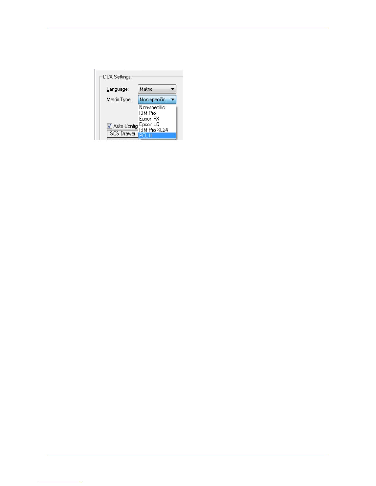
Language (Output data stream)
Select: PCL5, PostScript or Matrix
If Matrix is selected a list of sub matrix options becomes selectable:
Select between Matrix printer type: IBM Pro, IBM Pro XL 24, Epson FX, Epson
LQ, PCL II or Non-specific.
Remember to alter your Matrix printer accordingly in case it supports multiple
matrix printer languages.
Code Page
Select the required value: Default is 500 (Multinational). Value has to match
corresponding value on the host system.
AFP Tray Mapping
Is default set to ‘Auto Configuration’. The available trays are automatically imported
from the trays defined in the Physical Printer definitions. Trays can be re-mapped
by disabling the ‘Auto Configuration’ and click on the tray name and select the
required tray from the list. Only the tray type can be remapped.
Edge to Edge Support
When checked it will inform the host that the output printer supports print from
edge to edge (even if the printer is not capable of this).
When used with PostScript print the PrintServer will (if needed) scale down the
print to ensure print data is within allowed printable area.
When used with PCL the print data outside the allowed printable area might be
printed outside the actual paper. So use this option with consideration.
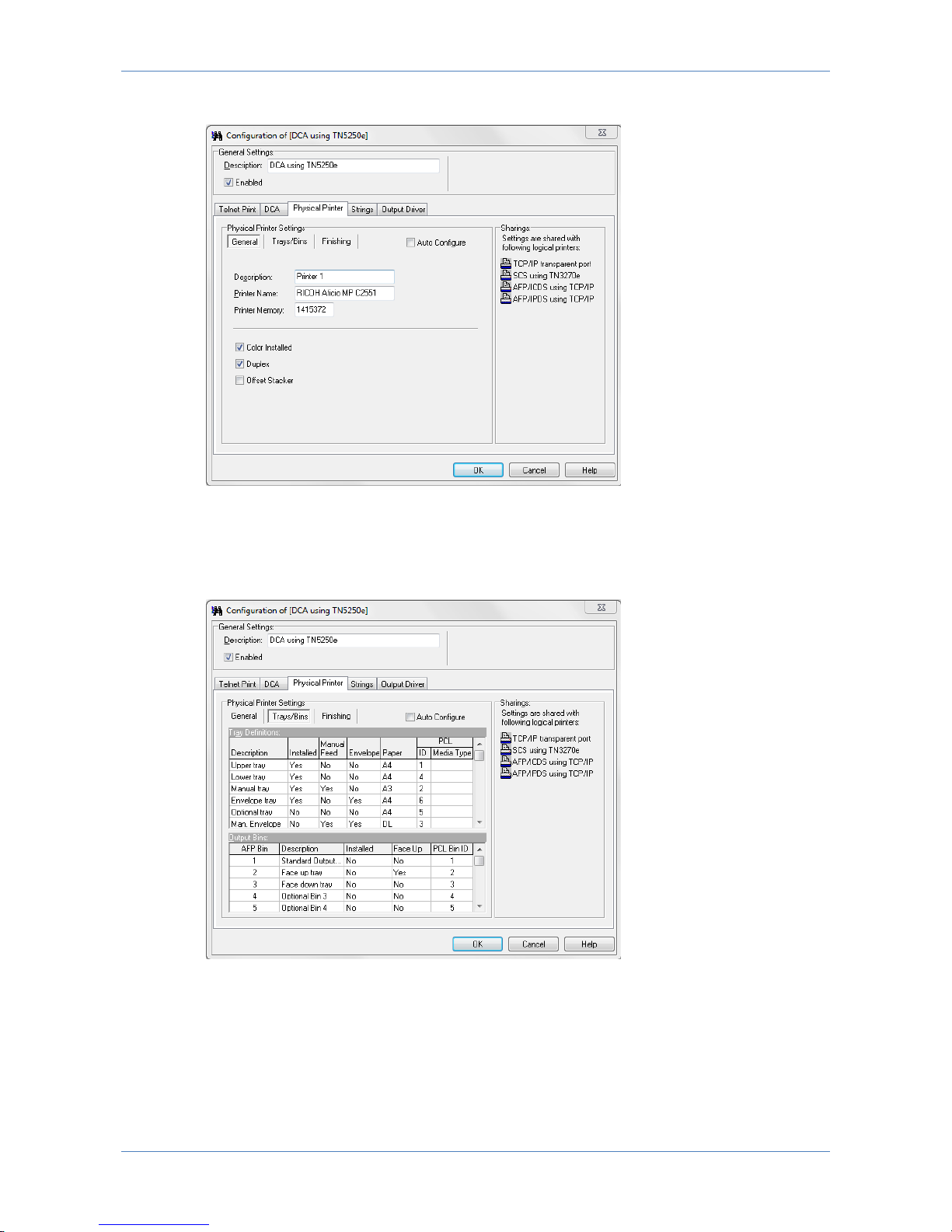
7.6.3 Physical Printer
These parameters are predefined when selecting the Printer Template (see 7.9
Printer templates). The Printer Template defines the target printer in the basic
version. Before any additional options installed in the printer can be accessed,
these must be enabled or defined via the below panels.
‘Auto Configure’ if checked, will attempt to retrieve information about Trays/Bins
paper format etc. directly from the printer. After selecting this option, changes
must be saved and the PrintServer restarted, as the information is collected during
the PrintServer start up. Enabling ‘Auto Configure’ disables manual configuration.
Page 36
LinkCom 5 User Manual
Page 36
General Printer Parameters
General Printer parameters describe the basic options of the printer: Description
and Printer name and printer memory. Colour, Duplex and Offset capabilities may
be enabled if supported by the printer.
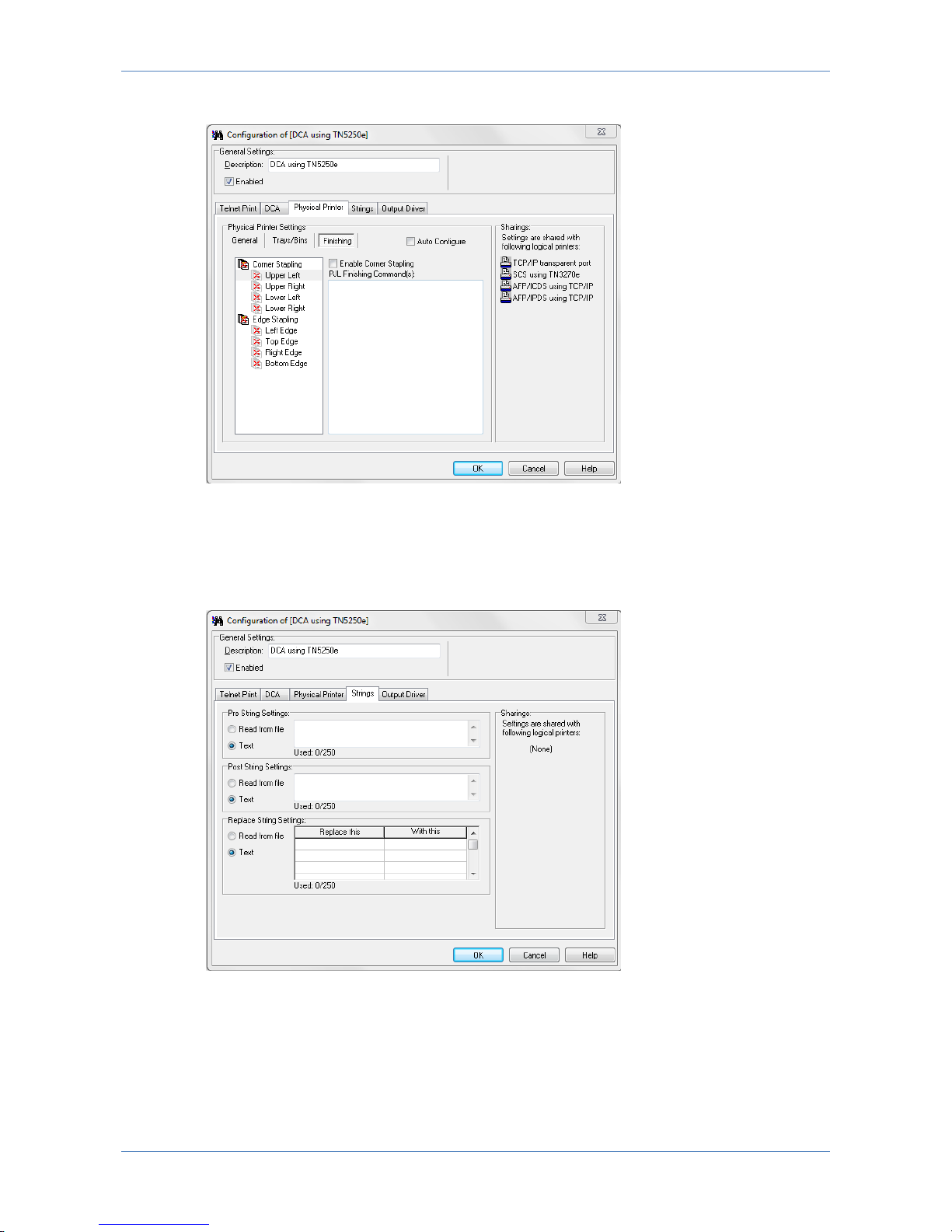
Trays/Bins
Trays/Bins describe and configure the input trays and output bins of the target
printer. Please refer to the printer’s technical manual for configuration of
PCL/PostScript ID’s.
Page 37
LinkCom 5 User Manual
Page 37
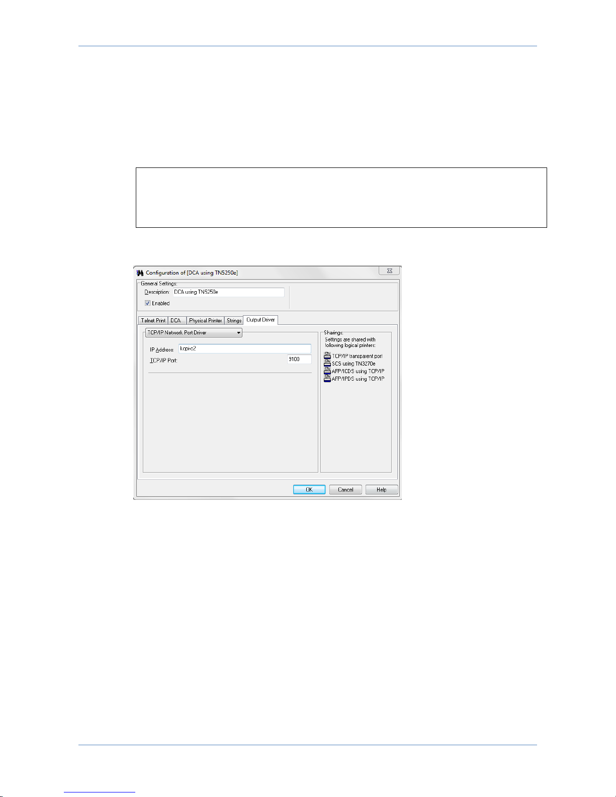
Finishing
Finishing defines the stapling option and is configurable if the Printer Template
contains a field for Finishing. Enable stapling for the actual option and consult the
printer’s technical manual for the PJL command to use.
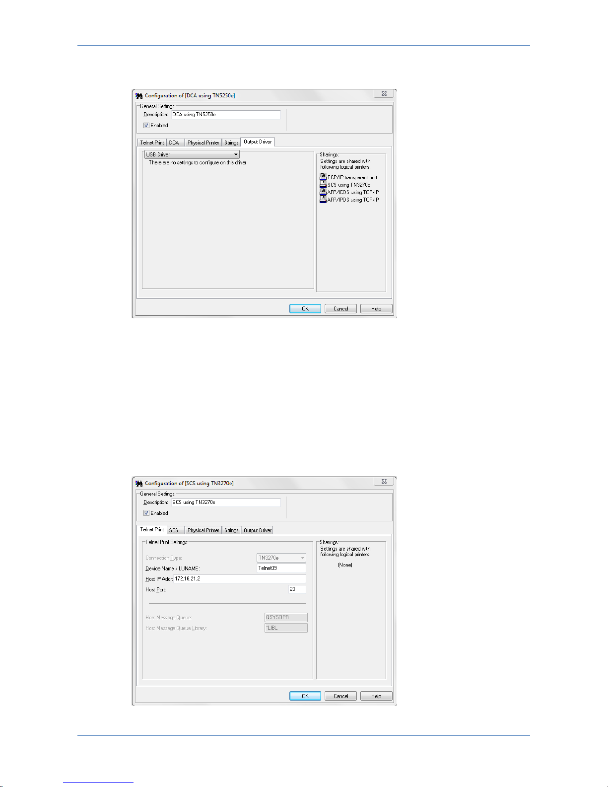
7.6.4 Strings
Strings can be used to send data to the printer before the job (Pre String Settings),
after the job (Post String Settings) or can be used to replace data send to the
printer (Replace String Settings). Strings can either be typed in directly, or
imported via a file.
Page 38
LinkCom 5 User Manual
Page 38
7.6.5 Output Driver
Output data from LinkCom 5 can be handled in various ways. Using the default
setup, the data is send to a network printer. “TCP/IP Network port driver”. The IP
Address input field is a text field, so the printer can be addressed using an IPv4
address, an IPv6 address or a DNS host name.
Example:
172.16.6.148
fe80::d2ff:50ff:fe8c:5ef8/64
printer2.company.org
The selected TCP/IP port (default is 9100) must be a RAW port type, and supported
by the printer.
Page 39
LinkCom 5 User Manual
Page 39
The output printer can also be a USB printer, in which case the PrintServer has to
be directly connected with the USB printer using a USB cable.
7.7 Configuring SCS transform
SCS transform supports LU1 non-graphic text only print from IBM 3270 mainframe.
The benefit of setting up SCS print with PrintGuide, is that when the IBM 3270 host
system IP address and intended SCS printer queue name have been entered the
LinkCom 5 PrintServer will automatically create and configure the SCS printer at
the IBM host. This gives less host system setup compared to e.g. an IPDS printer
setup.
7.7.1 Telnet Print
Page 40
LinkCom 5 User Manual
Page 40
Device Name / LUNAME
Fill in the Device name you would like to use. This name will automatically be
created as a printer name on your IBM 3270 Mainframe host.
Host IP address:
This is the IP address of the IBM mainframe host system.
Host Port number is 23 and is a predefined host port.
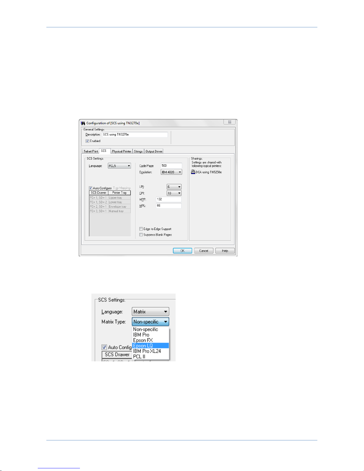
7.7.2 SCS
Language (Output data stream)
Select: PCL5, PostScript or Matrix
When Matrix is selected a list of sub matrix options become selectable:
Select between Matrix printer type: IBM Pro, IBM Pro XL 24, Epson FX, Epson
LQ, PCL II or Non-specific.
Remember to alter your Matrix printer accordingly in case it supports multiple
matrix printer languages.
Page 41

LinkCom 5 User Manual
Page 41
Code Page
Select the required value: Default is 500 (Multinational). Value has to match
corresponding value on the host system.
AFP Tray Mapping
AFP Tray Mapping is default set to ‘Auto Configuration’. The available trays are
automatically imported from the trays defined in the Physical Printer definitions.
Trays can be re-mapped by disabling the ‘Auto Configuration’, clicking on the tray
name and selecting the required tray from the list. Only the tray type can be
remapped.
Emulation
Defines the IBM emulation which is reported to the IBM host system.
Select the value as required: IBM 3812, IBM 3816, IBM 4028.
LPI
Lines per inch.
CPI
Characters per inch
MPP
Maximum characters per page. Defines the maximum characters available per page
width.
MPL
Maximum lines per page.
LPI, CPI, MPP, and MPL values has to be typed in according to host requirements.
Edge to Edge Support
Will when checked inform the host that the output printer supports print from edge
to edge (even if the printer is not capable of this).
When used with PostScript print the PrintServer will (if needed) scale down the
print to ensure print data is within the allowed printable area.
When used with PCL the print data placed outside the allowed printable area may
be printed outside the actual paper. So use this option with consideration.
Suppress Blank Pages
Can be used to avoid unintended blank pages as well as separator sheets.
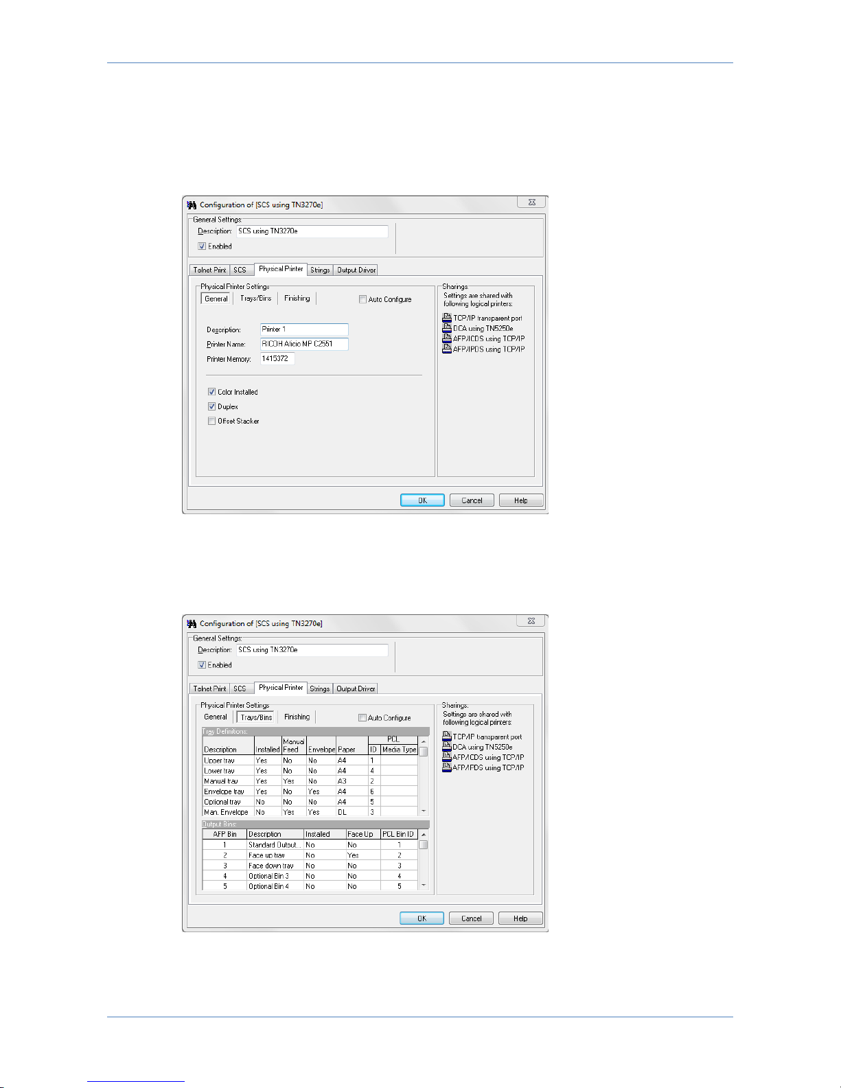
7.7.3 Physical Printer
These parameters are predefined when selecting the Printer Template (see 7.9
Printer templates). The Printer Template defines the target printer in the basic
version. These must be enabled or defined via the below panels before any
additional options installed in the printer can be accessed.
Page 42
LinkCom 5 User Manual
Page 42
When checked ‘Auto Configure’ will attempt to retrieve information about
Trays/Bins paper format etc. directly from the printer. After selecting this option,
save the changes and restart the PrintServer to collect the information during
PrintServer start up. Enabling ‘Auto Configure’ disables manual configuration.
General Printer Parameters
General Printer parameters describe the basic options of the printer: Description
and Printer name and printer memory. Colour, Duplex and Offset capabilities can be
enabled if supported by the printer.
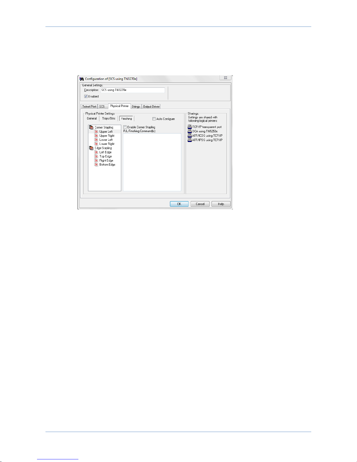
Trays/Bins
Page 43
LinkCom 5 User Manual
Page 43
Trays/Bins describe and configure the input trays and output bins of the target
printer. Please refer to the printer’s technical manual for configuration of
PCL/PostScript ID’s.
Finishing
Finishing define the stapling option and is configurable if the Printer Template
contain a field for Finishing. Enable stapling for the actual option and consult the
printer’s technical manual for the PJL command to use.
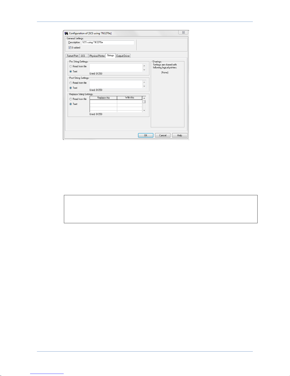
7.7.4 Strings
Strings are used to send data to the printer before the job (Pre String Settings),
after the job (Post String Settings) or can be used to replace data send to the
printer (Replace String Settings). Strings can either be typed in directly, or
imported via a file.
Page 44
LinkCom 5 User Manual
Page 44
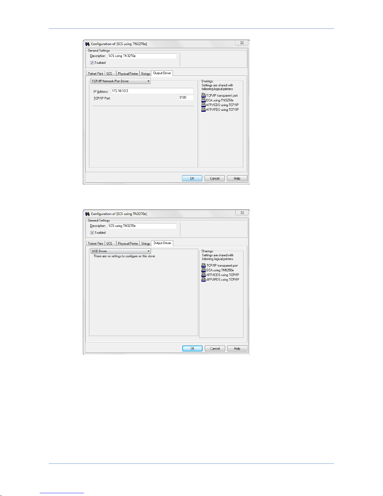
7.7.5 Output Driver
Output data from LinkCom 5 can be handled in various ways. Using the default
setup, the data is send to a network printer. “TCP/IP Network port driver”. The IP
Address input field is a text field, so the printer can be addressed using an IPv4
address, an IPv6 address or a DNS host name.
Example:
172.16.6.148
fe80::d2ff:50ff:fe8c:5ef8/64
printer2.company.org
The selected TCP/IP port (default is 9100) must be a RAW port type, and supported
by the printer.
Page 45
LinkCom 5 User Manual
Page 45
The output printer can also be a USB printer, in which case the PrintServer has to
be directly connected with the USB printer using a USB cable.
7.8 Configuring Transparent TCP/IP Printing
Transparent printing is intended for Windows PC’s, Servers or other TCP/IP host
systems needing to be able to print ordinary TCP/IP print. A LinkCom 5 PrintServer
is not required, as TCP/IP printing is normally handled directly between
host/PC/Server and printer.
The Transparent TCP/IP option makes no alterations to the print job. Any print data
sent to this port is transmitted straight to the output printer. Any response from the
printer e.g. paper low, paper jam etc. is likewise relayed back to the host.
Page 46
LinkCom 5 User Manual
Page 46
There are some situations where using the LinkCom 5 PrintServer for this type of
print is recommended.
Example 1
When printing to a USB connected printer that is not connected to the LAN and
cannot be reached through other channels.
Example 2
The host system needs to send special pre/post/replacement strings along with the
print jobs.
Example 3
In mixed environments where host output and office application output is sent to
the same printer.
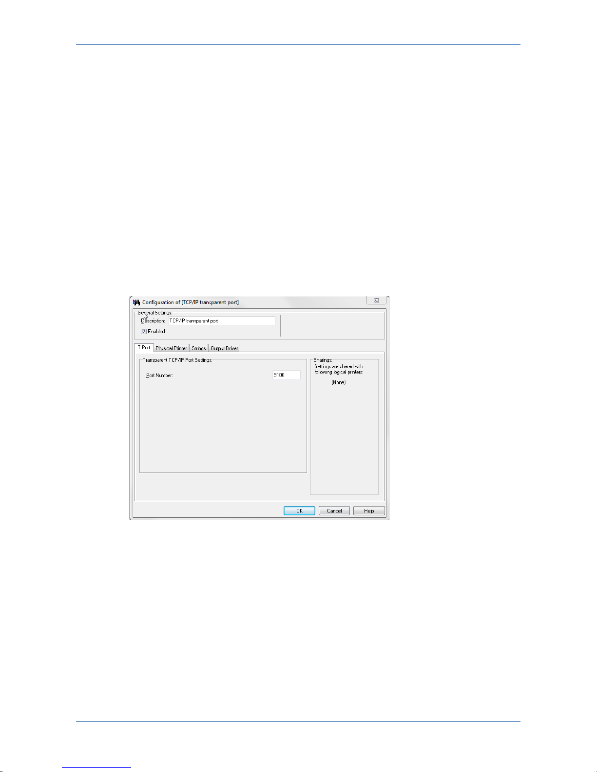
7.8.1 T Port
Port Number
This is the port number that the host system/PC/Server has to print to in order to
target TCP/IP print to the PrintServer. Default settings is TCP port 9100
(recommended), but can be any port as long as incoming print is in RAW format.
If selecting any other port than 9100 please ensure that the selected port number
does not conflict with other port assignments for transforms, devices or network.
Page 47
LinkCom 5 User Manual
Page 47
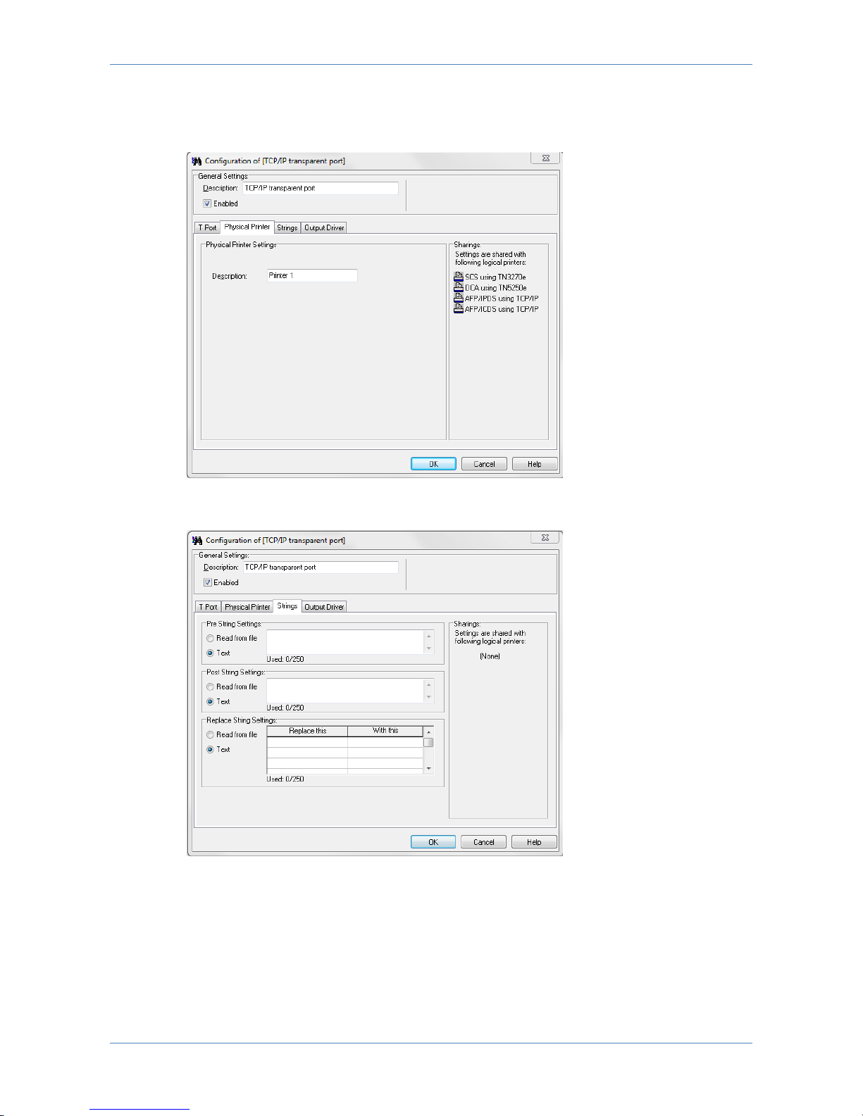
7.8.2 Physical Printer
Description: Name of the Printer.
7.8.3 Strings
Strings may be used to send data to the printer before the job (Pre String
Settings), after the job (Post String Settings) or can be used to replace data send
to the printer (Replace String Settings).
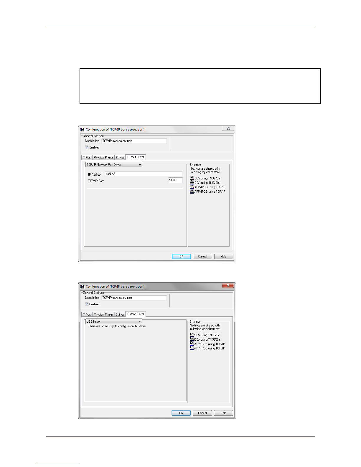
7.8.4 Output Driver
Output data from LinkCom 5 can be handled in various ways. Using the default
setup, the data is send to a network printer. “TCP/IP Network port driver”. The IP
Page 48
LinkCom 5 User Manual
Page 48
Address input field is a text field, so the printer can be addressed using an IPv4
address, an IPv6 address or a DNS host name.
Example:
172.16.6.148
fe80::d2ff:50ff:fe8c:5ef8/64
printer2.company.org
The selected TCP/IP port (default is 9100) must be a RAW port type, and supported
by the printer.
The output printer can also be a USB printer, in which case the PrintServer has to
be directly connected with the USB printer using a USB cable.
Page 49
LinkCom 5 User Manual
Page 49
7.9 Printer templates
Special printer features like stapling, stacking, addressing special input trays and
output bins etc. can be addressed and utilised. It is recommended to import a
Printer template file matching the selected output printer. Printer template files,
contain definitions that enables the usage of the above mentioned features. It also
ensures that trays are mapped correctly.
Printer template files comes preinstalled with PrintGuide. If a template file for your
specific printer model is not available try to use a template file designed for the
main printer model. If no compatible Printer template file is available MPI TECH
support may be able to create a usable template file.
Printer template files are applied to LinkCom 5 PrintServers from PrintGuide.
Highlight the LinkCom 5 print server
Go to menu “Print Server”
“Update Configuration”. (see Printer Definition Files in 2.1 Terms and definitions).
7.10 Internal LinkCom 5 web server
The LinkCom 5 features a built-in web server intended for presenting basic setup
and status.
While it is highly recommended to use PrintGuide for configuring LinkCom 5 some
settings can be managed using the internal web server.
7.10.1 Accessing the internal web server
The LinkCom 5 internal web server can be accessed in 2 ways:
Highlighting the device in PrintGuide, right click and select “Open in Web
Browser”, or
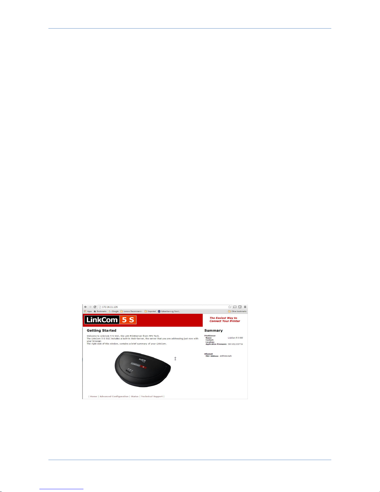
Type the IP address or hostname of the LinkCom 5 in your web browser.
The default page contains the summery information of the LinkCom PrintServer
including MAC Address and current firmware version.
Page 50
LinkCom 5 User Manual
Page 50
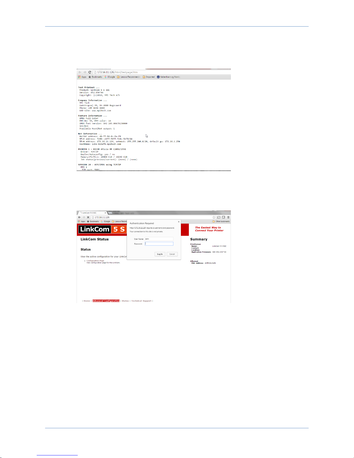
7.10.2 Status page with Configuration Page.
By selecting “Status”, “Configuration Page”, the Configuration Page can be viewed
without having to print it.
7.10.3 Advanced Configuration
If the LinkCom PrintServer has been configured with a password you will be
prompted before being granted access to this settings section.
Login as user “adm” with the assigned “adm” password.
Page 51
LinkCom 5 User Manual
Page 51
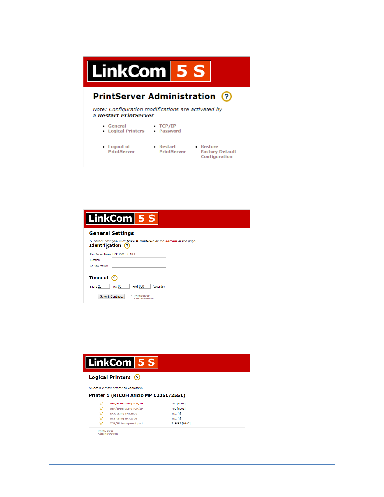
After changing a setting make sure to click “Save” and “Restart PrintServer”
otherwise changes will not take effect.
7.10.4 General
The “General Settings” controls settings for PrintServer name, Location information,
Contact person as well as different timeout settings for the PrintServer.
7.10.5 Logical Printers
This section controls settings with regards to the logical printers that are licensed
for this PrintServer. If a printer definition has been loaded this will also be
displayed.
Page 52
LinkCom 5 User Manual
Page 52
PPD settings
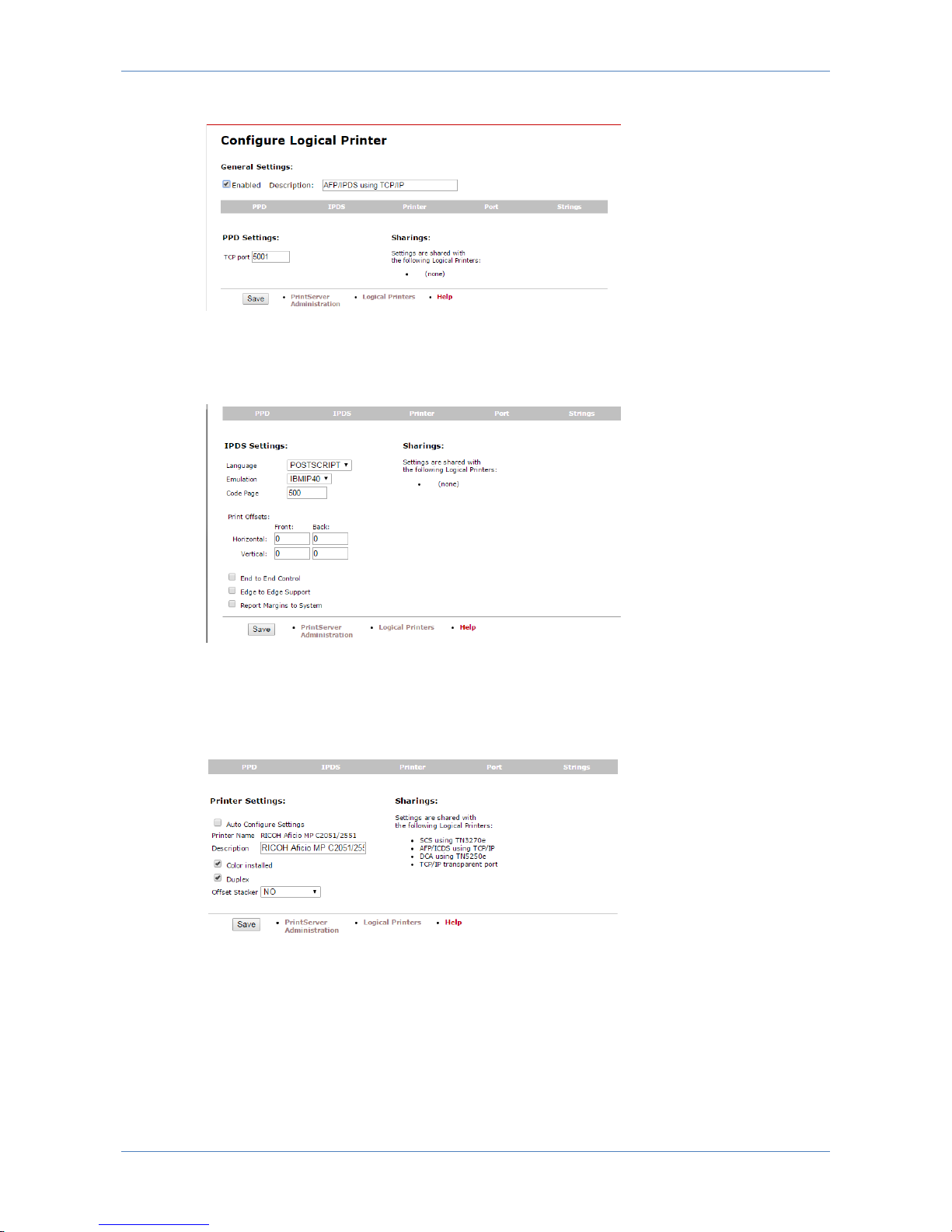
PPD settings allow enabling/disabling of the logical printer as well as controlling the
TCP input port used with this.
IPDS settings
IPDS settings provide access to almost the same controls that are available via
PrintGuide. Among them: Transform language, IBM Printer emulation, Code Page
and various other controls already explained in section 7.4
Printer settings
Printer settings provide access to some configuration of the selected output printer.
But use PrintGuide in order to view and manipulate AFP tray assignments,
trays/bins and finishing options.
Page 53
LinkCom 5 User Manual
Page 53
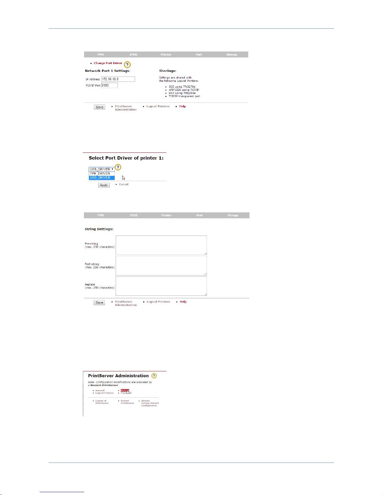
Network port settings
The Port sections allows for entering TCP/IP port as well as IP Address or DNS
name for the output printer. By clicking the “Change Port Driver” option, it is also
possible to change between USB and TCP/IP printing.
Sting settings
The Strings section options include entering Pre-,Post-, or Replace-strings to the
output printer. This is handy if the host sends commands to e.g. change fonts, and
this requires a special command sequence in order for the output printer to
understand.
7.10.6 TCP/IP section
The TCP/IP section gives access to network settings for the LinkCom 5 PrintServer.
It includes DHCP assigned or manual assigned IP address, hostname, Gateway and
DNS server entries.
Page 54
LinkCom 5 User Manual
Page 54
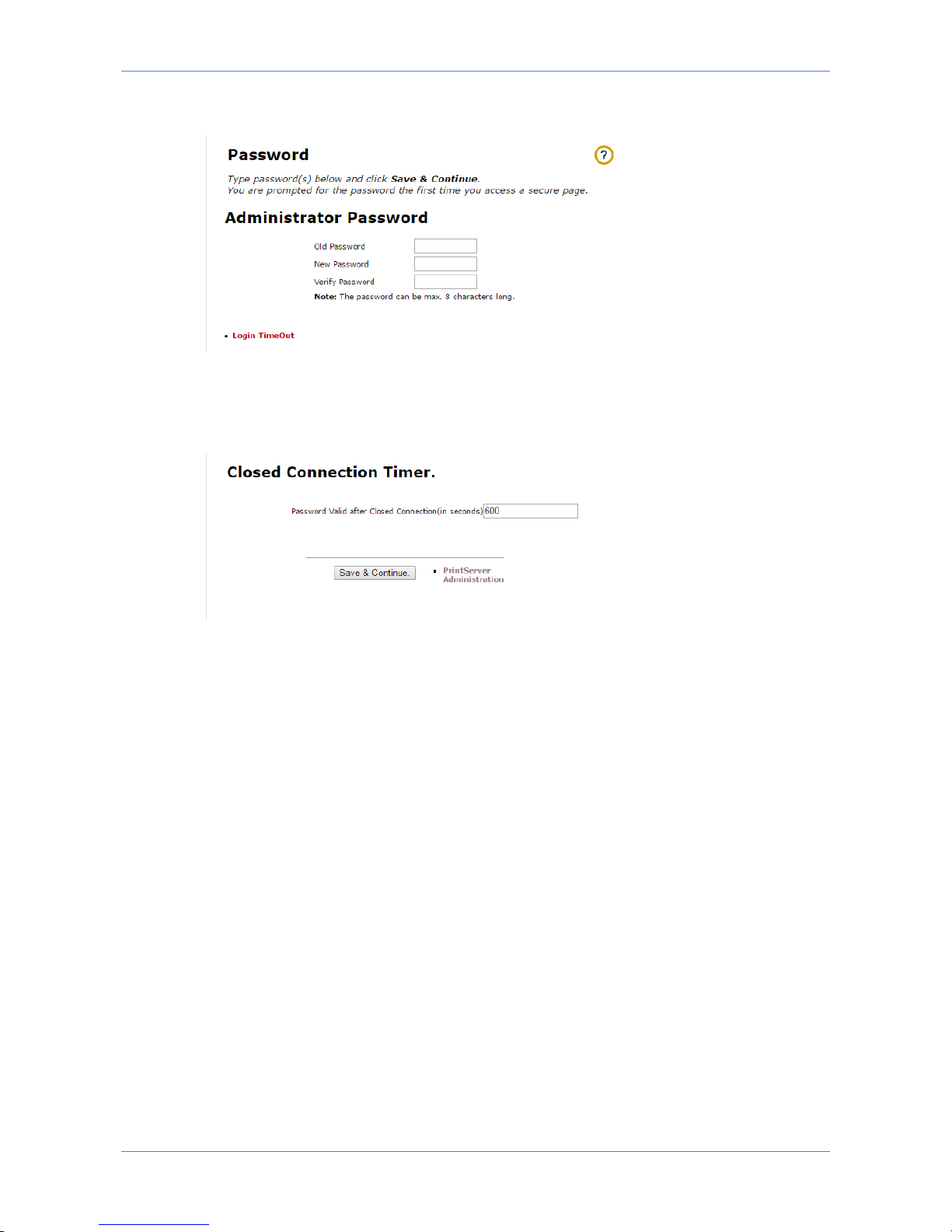
7.10.7 Password section
The Password section enables setting or changing the LinkCom 5 PrintServer
password. To apply changes, type in current password, enter and re-enter the new
password. If no password (= “adm” ) has been assigned the current password will
be adm.
Pressing the link for “Login TimeOut” will set the timeout for a password login.
Within the timeout, a logged-in user opening a new web browser will not be
prompted for password.
When timeout has passed and no activity has been registered, an automatic logout
from the PrintServer takes place.
7.10.8 Logout of web server
Pressing the “Logout of PrintServer” causes the adm user to be logged out of the
PrintServer web server.
7.10.9 Restart PrintServer
Pressing the “Restart PrintServer” causes the PrintServer to restart. A restart is
needed after having performed configuration changes, and having saved changes.
7.10.10 Restore Factory Default Configuration.
Pressing the Restore Factory option causes all of the LinkCom 5 configuration
(except for eventual password) to be cleared and reset to factory defaults.
Remember after resetting, to perform a PrintServer restart, e.g. by selecting
“Advanced Configuration” followed by “Restart PrintServer”
Page 55
LinkCom 5 User Manual
Page 55
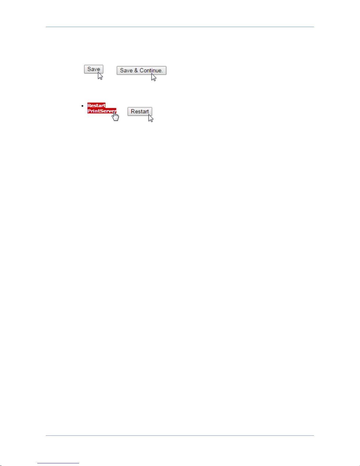
7.10.11 Remember to save changes and restart PrintServer
Any change performed has to be committed by pressing the “Save” or “Save &
Continue” followed by a “Restart PrintServer”
Wait for the LinkCom 5 PrintServer to be online again.
Page 56

LinkCom 5 User Manual
Page 56
8 Configuration of host systems
The host system must be setup to allow printing via the LinkCom 5 PrintServer. The
actual setup depends on the host system. If in doubt, please consult the host
system manual. Please note that the host system sees the LinkCom 5 PrintServer
as a printer.
8.1 Setup in mainframe TCP/IP environment
The descriptions in the sections below relate to the different print options from IBM
Mainframe / System z-series.
8.2 PSF/MVS AFP/IPDS printing
This section provides you with the PSF Start-up Procedures
Once these parameters have been configured, and the basic installation of the
LinkCom 5 PrintServer has been completed, direct AFP / IPDS from PSF / MVS is
possible.
Requirements:
PSF/MVS version 2.2.0 with PTF level UW21345 or higher
TCP/IP ver. 2, Rel. 1 or higher
Interlink TCP/Access Ver.3.1 or higher
8.2.1 PSF/MVS start-up procedure
Using IP address 192.0.110.21 and port number 5001.
The IP address of the LinkCom 5 PrintServer should be programmed in the IP-
address (IPADDR=‘192.0.110.21’). The port number (PORTNO=5001) is the default
port number of the IPDS port in print server.
8.3 PSS/MVS AFP/ICDS printing
This section provides:
000001 //PSF4 PROC
000002 //STEP01 EXEC PGM=APSPPIEP,REGION=1750K
.
.
.
000034 //******************************************************************
000035 //* STANDARD PRINTDEV */
000036 //*****************************************************************
000037 //PRT420 CNTL
000038 //PRT420 PRINTDEV FONTDD=*.FONT01, /* FONT LIBRARY DD */
.
.
.
000058 // IPADDR=‘192.0.110.21’ /* IP ADDRESS */
000059 // PORTNO=5001 /* PORT NUMBER */
000060 //PRT420 ENDCNTL
Page 57
LinkCom 5 User Manual
Page 57
PSS Start-up Procedure
PSS Printer Profile
Once these parameters have been configured and the basic TCP/IP installation of
the LinkCom 5 PrintServer has been completed, direct AFP / ICDS from PSS / MVS
is possible.
Requirements:
PSS, version 6.01 or higher
TCP/IP for MVS, version 2, release 1 or higher
Interlink TCP/Access Ver.3.1 or higher
8.3.1 PSS printer profile using TCP/IP attachment
*TCPIP DEFINITIONS
TCPIP USER=TCPIP
NAMESRV IP=192.0.15.0
NAMESRV IP=192.0.14.1
*------------------------------------------------------------------* PSS PRINTER DEFINITION FOR USE WITH DIRECT TCP/IP CONNECTION
*------------------------------------------------------------------PRINTER PRTID=PRT411,IP=192.0.110.21,
PORT=5005
*-------------------------------------------------------------------
Example of PSS printer profile using TCP/IP
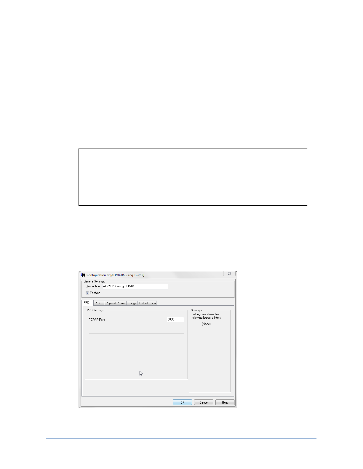
The IP address of the LinkCom 5 print server should be programmed in the IP-
address (IPADDR=‘192.0.110.21’). The port number (PORTNO=5005) is the default
port number of the first ICDS port in the print server. The PrintGuide dialogue
below allows you to enter the TCP/IP Port. See Getting Started with PrintGuide,
doc. no. 60364.
Page 58

LinkCom 5 User Manual
Page 58
8.4 PSS/VM AFP printing using TCP/IP
This section provides: PSS VM printer profile statements.
Once these parameters have been configured, and the basic TCP/IP installation of
the LinkCom 5 PrintServer has been completed, direct AFP / ICDS from PSS / VM
will be possible.
Requirements:
PSS, version 6.01 or higher
TCP/IP for VM, version 2, release 2.1 or higher
8.4.1 Sample PSS VM printer profile definition using
TCP/IP
KEY KEY=12345678901234567890
CONSLOG NO
********************TCP/IP DEFINITIONS*********************
*
TCPIP USER=TCPIP
NAMESERV IP=192.0.15.0
NAMESERV IP=192.0.15.1
*
*******************TCP/IP ATTACHMENT************************
*
PRINTER PRTID=NET022,IP=192.0.110.21,PORT=5005
*
************************************************************
The IP address of the LinkCom 5 print server should be programmed in the IP-
address (IPADDR=‘192.0.110.21’). The port number (PORTNO=5005) is the default
port number of the ICDS port in the print server. The PrintGuide dialogue allows
you to enter the TCP/IP Port. See Getting Started with PrintGuide, doc. no. 60364.
8.5 Setup in OS/400 TCP/IP environment
The description in the below sections relates to the different print options from IBM
platforms running OS/400.
8.6 PSF/400 AFP Printing Using TCP/IP
This chapter provides configuration guidelines for iSeries IPDS Printing over TCI/IP.
These guidelines are applicable for OS/400 version 3.7 and up.
The examples of completed screens given are for OS/400 version 4.X and 5.X and
may vary slightly compared to different OS versions.
Requirements:
Before IPDS printing using TCP/IP can be accomplished, the following points need
to be checked:
TCP/IP is installed and started.
IBM Print Services Facility/400 (PSF) is installed.
Page 59

LinkCom 5 User Manual
Page 59
8.7 AS/400 / iSeries Settings for Version 3.7, - 7.x
To configure IPDS printing on OS/400 from version 3.7 to V7 it is necessary to
create a Printer Device Description. It is also highly recommended to create a PSF
configuration as this includes additional printer settings and e.g. media size
information used with matrix printers. These are created using the following
commands:
CRTPSFCFG
CRTDEVPRT
8.7.1 Creating the PSF configuration
On the iSeries command line, enter a command in the form:
CRTPSFCFG PSFCFG(AFP/NETWRKPRT) IPDSPASTHR(*YES) RLSTMR(*SEC15)
TEXT('<Optional Text description> ')
Where:
AFP is the name an existing library in which the PSF configuration is to be located
and NETWRKPRT is the name given to the PSF configuration object. Any existing
library and a name of choice for the object can be substituted here but the same
values must be used in the creation of the Printer Device Description in the next
step.
<Optional Text description> is an optional text description for the PSF
configuration object.
A completed PSF Configuration looks like this:
PSF Configuration Information Page 1
PSF configuration: NETWRKPRT Library: AFP
User resource library . . . . . . . . . . . . . : *JOBLIBL
IPDS pass through . . . . . . . . . . . . . . . : *YES
Activate release timer. . . . . . . . . . . . . : *NORDYF
Release timer . . . . . . . . . . . . . . . . . : *SEC15
Restart timer . . . . . . . . . . . . . . . . . : *IMMED
SNA retry count . . . . . . . . . . . . . . . . : 2
Delay time between retries. . . . . . . . . . . : 0
Blank page. . . . . . . . . . . . . . . . . . . : *YES
Page size control . . . . . . . . . . . . . . . : *YES
Resident fonts. . . . . . . . . . . . . . . . . : *YES
Resource retention. . . . . . . . . . . . . . . : *YES
Edge orient . . . . . . . . . . . . . . . . . . : *NO
Remote location:
Name or address . . . . . . . . . . . . . . . . : *NONE
TCP/IP port . . . . . . . . . . . . . . . . . . : *NONE
TCP/IP activation timer . . . . . . . . . . . . : 170
PSF defined options: *NONE
Text description. . . . . . . . . . . . . . . . :<Optional Text description>
Device resource library list: *DFT
Page 60

LinkCom 5 User Manual
Page 60
8.7.2 Creating the Printer Device Description
On the iSeries command line, enter a command in the form:
CRTDEVPRT DEVD(<DeviceName>) DEVCLS(*LAN) TYPE(*IPDS) MODEL(0)
LANATTACH(*IP) AFP(*YES) PORT(5001) FONT(11) FORMFEED(*AUTOCUT)
RMTLOCNAME(‘192.194.134.90’) USRDFNOBJ(AFP/NETWRKPRT *PSFCFG)
TEXT('<Option Txt Description> ')
Where:
<DeviceName> is the selected name for the printer Device Description which will
also be used as the name for the Output Queue.
AFP is the name of the library in which the PSF configuration was created in the
previous step.
NETWRKPRT is the name given to the PSF configuration in the previous step.
5001 is by default the port number for the first printer session. Any subsequent
printer sessions will use port no 5002, 5003, 50xx etc.
RMTLOCNAME is the IP address of the LinkCom 5 print server. All printer sessions
printing via the LinkCom 5 print server must point to this IP address.
<Option Txt description> is an optional text description for the Printer Device
Description object.
A completed Device Description looks like this:
Page 61

LinkCom 5 User Manual
Page 61
Display Device Description Page 1
5716SS1 V4R4M0 981108 BLDRB1 09/11/98 12:02:59
Device description . . . . . . . . : DEVD <DeviceName>
Option . . . . . . . . . . . . . . : OPTION *ALL
Category of device . . . . . . . . : *PRT
Device class . . . . . . . . . . . : DEVCLS *LAN
Device type. . . . . . . . . . . . : TYPE *IPDS
Device model . . . . . . . . . . . : MODEL 0
LAN attachment . . . . . . . . . . : LANATTACH *IP
User-defined object . . . . . . . : USRDFNOBJ NETWRKPRT
Library. . . . . . . . . . . . . . : AFP
Object type. . . . . . . . . . . . : *PSFCFG
Data transform program . . . . . . : USRDTATFM *NONE
User-defined driver program . . . .: USRDRVPGM *NONE
Advanced function printing . . . . : AFP *YES
Port number. . . . . . . . . . . . : PORT 5001
Online at IPL. . . . . . . . . . . : ONLINE *YES
Font . . . . . . . . . . . . . . . : FONT
Identifier . . . . . . . . . . . . : 011
Point size . . . . . . . . . . . . : *NONE
Form feed. . . . . . . . . . . . . : FORMFEED *AUTOCUT
Separator drawer . . . . . . . . . : SEPDRAWER *FILE
Separator program. . . . . . . . . : SEPPGM *NONE
Library. . . . . . . . . . . . . . :
Printer error message. . . . . . . : PRTERRMSG *INQ
Message queue. . . . . . . . . . . : MSGQ QSYSOPR
Library. . . . . . . . . . . . . . : *LIBL
Activation timer . . . . . . . . . : ACTTMR 170
Maximum pending requests . . . . . : MAXPNDRQS 6
Print while converting . . . . . . : PRTCVT *YES
Print request timer. . . . . . . . : PRTRQSTMR *NOMAX
Form definition. . . . . . . . . . : FORMDF F1C10110
Library. . . . . . . . . . . . . . : *LIBL
Remote location. . . . . . . . . . : RMTLOCNAME
Name or address. . . . . . . . . . : '192.194.134.90'
Dependent location name. . . . . . : DEPLOCNAME *NONE
Text . . . . . . . . . . . . . . . : TEXT <Option Txt Description>
User-defined options . . . . . . . : USRDFNOPT
-----------------User-defined options------------------
Do the following:
Ping the IP address to verify communication with the printer:
PING ’192.194.134.90’
Vary the printer on:
VRYCFG <DeviceName> CFGTYPE(*DEV) STATUS(*ON)
Start the print writer:
STRPRTWTR <DeviceName>
Page 62

LinkCom 5 User Manual
Page 62
9 SCS/DCA printing using
TN3270e/TN5250e
This chapter provides examples of how to set up SCS/DCA printing using TN3270e
and TN5250e protocols.
9.1 TN3270e setup using OS/390 communication
server
The IBM OS/390 ver. 2.8 is capable of supporting TN3270e sessions communicating
directly. The following describes the required mainframe definitions for a LinkCom
or DocOut. It is assumed that the TN3270e service is already active on the
mainframe.
9.1.1 Mainframe TCPIP profile definitions:
PRTGROUP PRTGRP1
LU08
TCPPRT01 TCPPRT02 TCPPRT03 TCPPRT04 TCPPRT05
TCPPRT06 TCPPRT07 TCPPRT08 TCPPRT09 TCPPRT10
TCPPRT11 TCPPRT12 TCPPRT13 TCPPRT14 TCPPRT15
ENDPRTGROUP
IPGROUP IPGRP1 255.255.0.0:128.0.0.0 ENDIPGROUP
LUMAP LUGRP1 IPGRP1 SPECIFIC PRTGRP1
PRTMAP PRTGRP1 IPGRP1
************
9.2 TN5250e set-up
To set up TN5250, first configure LinkCom 5 using PrintGuide please follow section
7.6.
On many iSeries installations, a device is automatically set up on the iSeries when
LinkCom 5 is booted. For this to happen, the following conditions apply:
Telnet must be started.
The QUATOVRT SYSVAL parameter must be set to a value that is higher than
the number of auto-configured virtual controllers currently running on the
system.
On some installations, the QAUTOVRT SYSVAL parameter is set to 0. This prevents
any virtual controllers being auto-created. In cases where QAUTOVRT SYSVAL
cannot be changed from 0, devices must be configured manually.
Page 63

LinkCom 5 User Manual
Page 63
9.2.1 Auto-configuration of devices
How to set up your iSeries to auto-configure devices:
Issue the command:
WRKCTLD *VWS
This will determine the number of auto-configured Virtual Controllers on the
system.
Issue the command:
DSPSYSVAL QAUTOVRT
If the system value of QAUTOVRT is equal to the number of auto-configured
Virtual Controllers, the QAUTOVRT value should be increased by the number of
devices that will be configured.
9.2.2 Manual Configuration of Devices
This section describes how to create printer definitions on iSeries that have the
QAUTOVRT SYSVAL parameter set to 0. (Normally PrintGuide running the LinkCom
5 DCA setup will automatically have created the printing device)
Prerequisites:
iSeries is configured and running TCP/IP
iSeries PTF level is at the levels described in APAR II10918. Check IBM's
support page for a list of PTFs to be installed for the different versions of
iSeries for TN5250e printing support.
http://www.as400.ibm.com/clientaccess/caiixd1.htm
Firmware level* on the interface is at least S80 xxx.360
Configure iSeries.
Start TCP/IP if not already started by typing STRTCP on the command line.
Method 1: Using the Command Line
Create the device from the Command Line by typing:
CRTDEVPRT DEVD(DEVXXXX) DEVCLS(*VRT) TYPE(3812) MODEL(1)
CTL(QVIRCD0001) FONT(87) TEXT(‘MANUAL CREATION OF VIRTUAL DEVICE
DEVXXXX’)
The value for DEVD should match the Device Name assigned in PrintGuide.
The value of CTL should match the virtual controller on the system (Normally
QVIRCD0001)
The value for TEXT is optional.
Page 64

LinkCom 5 User Manual
Page 64
MAIN iSeries Main Menu
System: S4449156
Select one of the following:
1. User tasks
2. Office tasks
3. General system tasks
4. Files, libraries, and folders
5. Programming
6. Communications
7. Define or change the system
8. Problem handling
9. Display a menu
10. Information Assistant options
11. Client Access/400 tasks
90. Sign off
Selection or command
===> CRTDEVPRT DEVD(DEVXXXX) DEVCLS(*VRT) TYPE(3812)
MODEL(1)CTL(QVIRCD0001) FONT(087) TEXT('MANUAL CREATION OF VIRTUAL
DEVICE DEXXXX')
F3=Exit F4=Prompt F9=Retrieve F12=Cancel F13=Information
Assistant F23=Set initial menu
Check the status of the device is Vary on Pending. The device will remain in this
state until the defined Print Server has established the session. This is done by
restarting the LinkCom 5 from PrintGuide.
Page 65

LinkCom 5 User Manual
Page 65
Method 2: Using Device Definition panels
The Device can also be created using the same values from the Work with Device
Definition Screens using option F4.
The value for DEVD should match the Device Name given in PrintGuide.
The value of CTL should match the virtual controller on the system (Normally
QVIRCD0001)
The value for TEXT is optional.
Create Device Desc (Printer) (CRTDEVPRT)
Type choices, press Enter.
Device description . . . . . . . DEVD > DEVXXXX
Device class . . . . . . . . . . DEVCLS > *VRT
Device type . . . . . . . . . . TYPE > 3812
Device model . . . . . . . . . . MODEL > 1
Online at IPL . . . . . . . . . ONLINE *YES
Attached controller . . . . . . CTL > QVIRCD0001
Font: FONT
Identifier . . . . . . . . . . > 087
Point size . . . . . . . . . . *NONE
Form feed . . . . . . . . . . . FORMFEED *TYPE
Separator drawer . . . . . . . . SEPDRAWER *FILE
Separator program . . . . . . . SEPPGM *NONE
Library . . . . . . . . . . .
Printer error message . . . . . PRTERRMSG *INQ
Message queue . . . . . . . . . MSGQ QSYSOPR
Library . . . . . . . . . . . *LIBL
More...
F9=All parameters F11=Choices F14=Command string F24=More
keys
Page 66

LinkCom 5 User Manual
Page 66
Check the status of the device is Vary on Pending. The device will remain in this
state until the defined PrintServer has established the session. This is done by
restarting; either from PrintGuide or by switching power off and afterwards on.
Create Device Desc (Printer) (CRTDEVPRT)
Type choices, press Enter.
Host print transform . . . . . . TRANSFORM *NO
User-defined options . . . . . . USRDFNOPT *NONE
+ for more values
User-defined object: USRDFNOBJ
Object . . . . . . . . . . . . *NONE
Library . . . . . . . . . .
Object type . . . . . . . . .
Data transform program . . . . . USRDTATFM *NONE
Library . . . . . . . . . . .
User-defined driver program . . USRDRVPGM *NONE
Library . . . . . . . . . . .
Text 'description' . . . . . . . TEXT > 'Manual Def of
DEVXXXX'
More...
F9=All parameters F11=Choices F14=Command string F24=More
keys
Page 67

LinkCom 5 User Manual
Page 67
10 LED signalling explained in details
The three LED lights on the front of the LinkCom 5 PrintServer (PRT, SES and LAN)
each have four states:
LED OFF
LED ON constantly lit
LED flashing slowly (approx. 50 times per minute)
LED flashing fast (approx. 100 times per minute)
LED combinations and explanations
The table shows all possible LED combinations and lists the messages linked to
them (Fast = flashing fast, Slow = flashing slowly).
PRT LED
SES LED
LAN LED
Explanation
Off
Off
Off
The PrintServer is powered off, or has not yet
initiated the start-up procedure
Off
Off
On
Off
Off
Slow
The PrintServer was not able to successfully
complete network start-up. Possible cause: A
DHCP server was not found. Or missing
network link.
Off
Off
Fast
No network connectivity. E.g. there could be a
cabling problem
Off
On
Off Off
On
On
Off
On
Slow
Off
On
Fast
Off
Slow
Off
Off
Slow
On
Inbound data being received. E.g. from host
system.
Off
Slow
Slow
Off
Slow
Fast
Off
Fast
Off
Off
Fast
On
Off
Fast
Slow
Page 68

LinkCom 5 User Manual
Page 68
Off
Fast
Fast
On
Off
Off On
Off
On On
Off
Slow
On
Off
Fast
On
On
Off
On
On
On
The PrintServer has entered a failed state, and
needs to be power cycled.
On
On
Slow
On
On
Fast
On
Slow
Off
On
Slow
On
On
Slow
Slow
On
Slow
Fast
On
Fast
Off On
Fast
On
On
Fast
Slow
On
Fast
Fast
Slow
Off
Off
Slow
Off
On
Outbound activity towards printer.
Slow
Off
Slow
Slow
Off
Fast
Slow
On
Off
Slow
On
On
Slow
On
Slow
Slow
On
Fast
Slow
Slow
Off
Slow
Slow
On
Outbound activity towards printer
Page 69

LinkCom 5 User Manual
Page 69
Slow
Slow
Slow
Slow
Slow
Fast
Slow
Fast
Off Slow
Fast
On
Slow
Fast
Slow
Slow
Fast
Fast
Fast
Off
Off
Fast
Off
On
Problem towards printer
Fast
Off
Slow
Fast
Off
Fast
Fast
On
Off Fast
On
On
Problem towards printer.
Fast
On
Slow
Fast
On
Fast
Fast
Slow
Off
Fast
Slow
On
Problem towards printer.
Fast
Slow
Slow
Fast
Slow
Fast
Fast
Fast
Off Fast
Fast
On
Problem towards printer.
Fast
Fast
Slow
Fast
Fast
Fast
Page 70
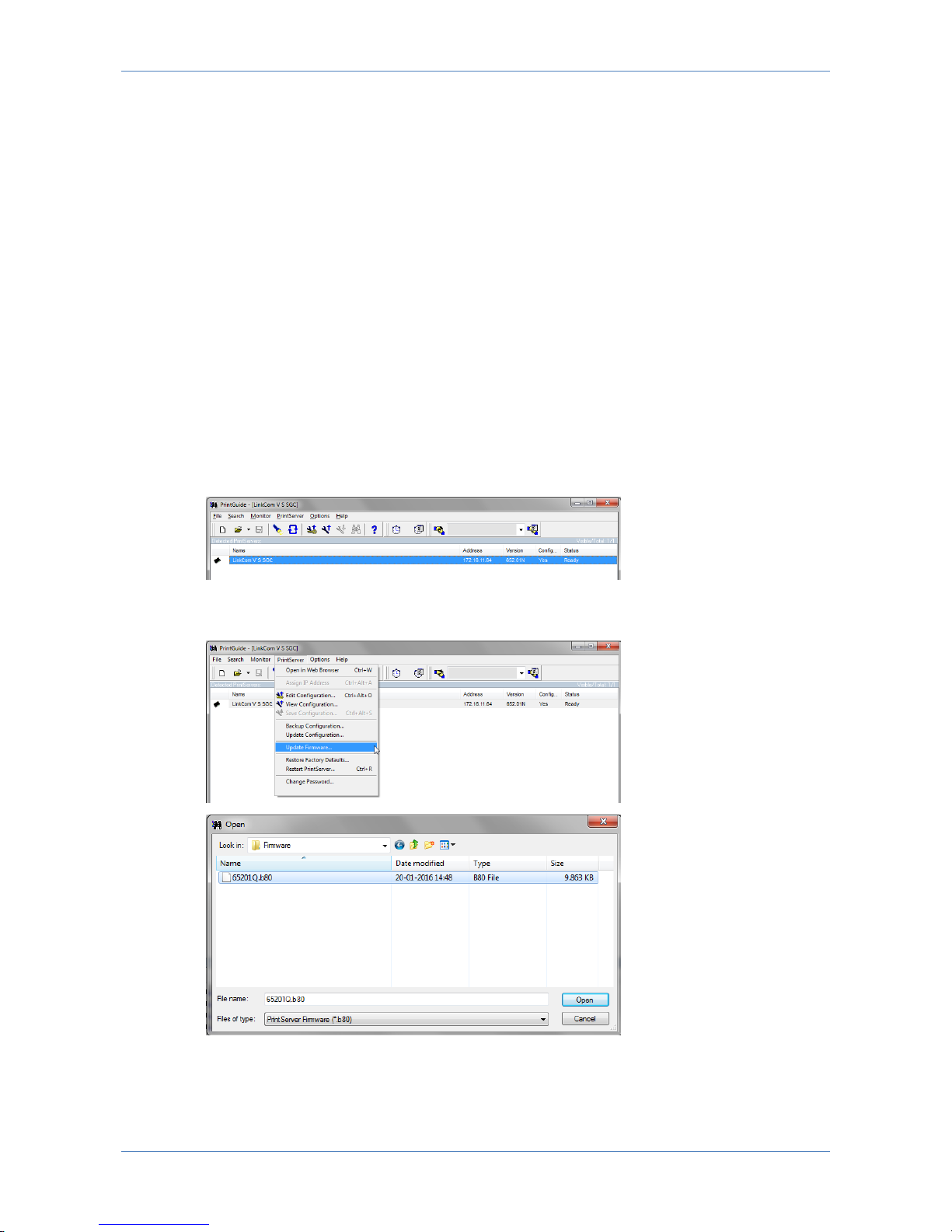
LinkCom 5 User Manual
Page 70
11 Updating firmware
MPI Tech releases updates containing error corrections and/or feature updates for
LinkCom 5 PrintServers. Firmware updates are available to customers with valid
maintenance.
11.1 How to update firmware
Firmware from MPI Tech has a numbering sequence that aligns firmware with the
right PrintServer product. Firmware for the LinkCom 5 PrintServer uses the naming
convention: 652xxx.b80.
Firmware is updated using PrintGuide, and by applying the received firmware file to
the hardware PrintServer.
11.2 Updating firmware with PrintGuide
Open PrintGuide, and in PrintGuide highlight the PrintServer you want to firmware
update.
Go to menu “PrintServer”, “Update Firmware” and browse to the location of your
652xxx.b80 firmware file
Page 71
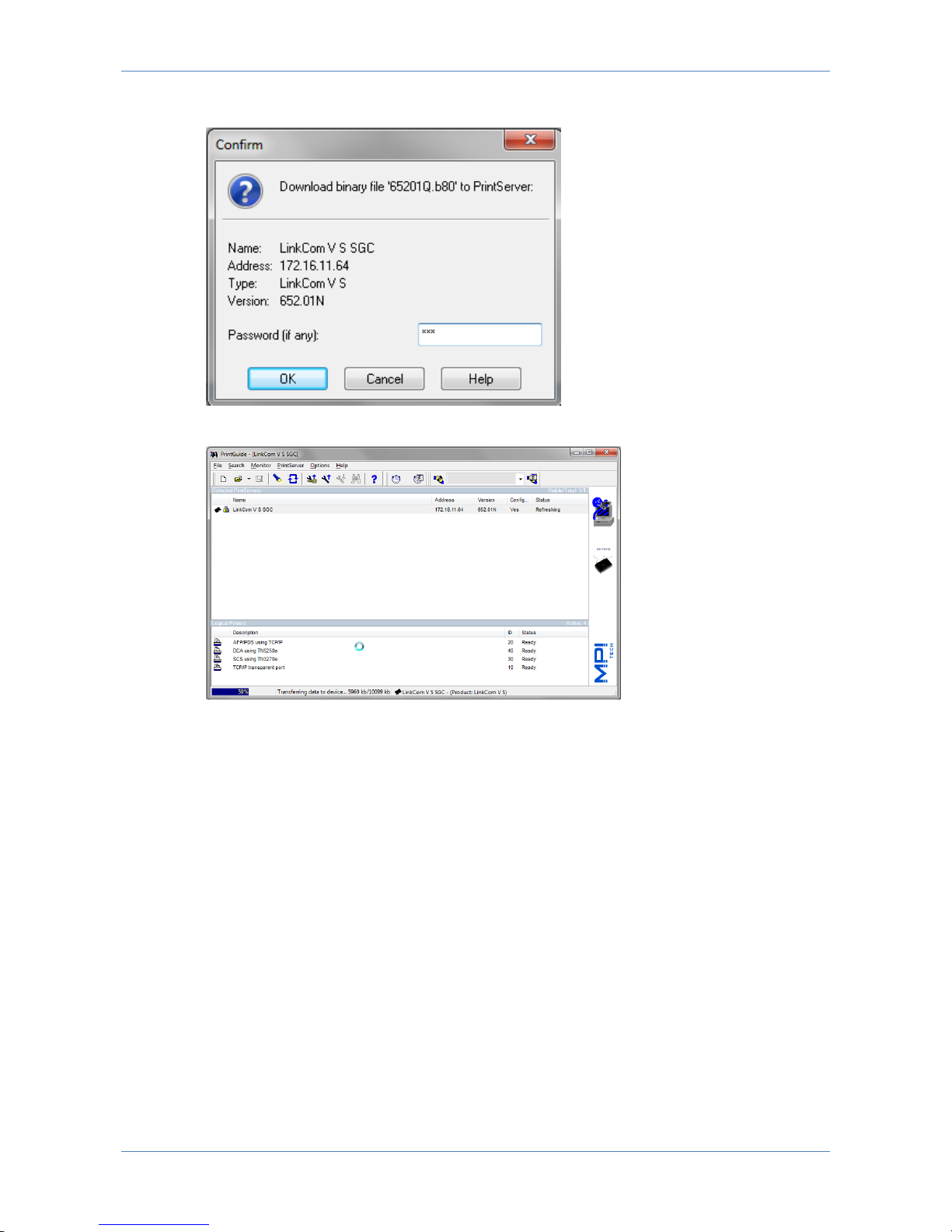
LinkCom 5 User Manual
Page 71
Accept firmware download to the PrintServer.
The PrintServer will automatically restart after uploading the new firmware.
Page 72
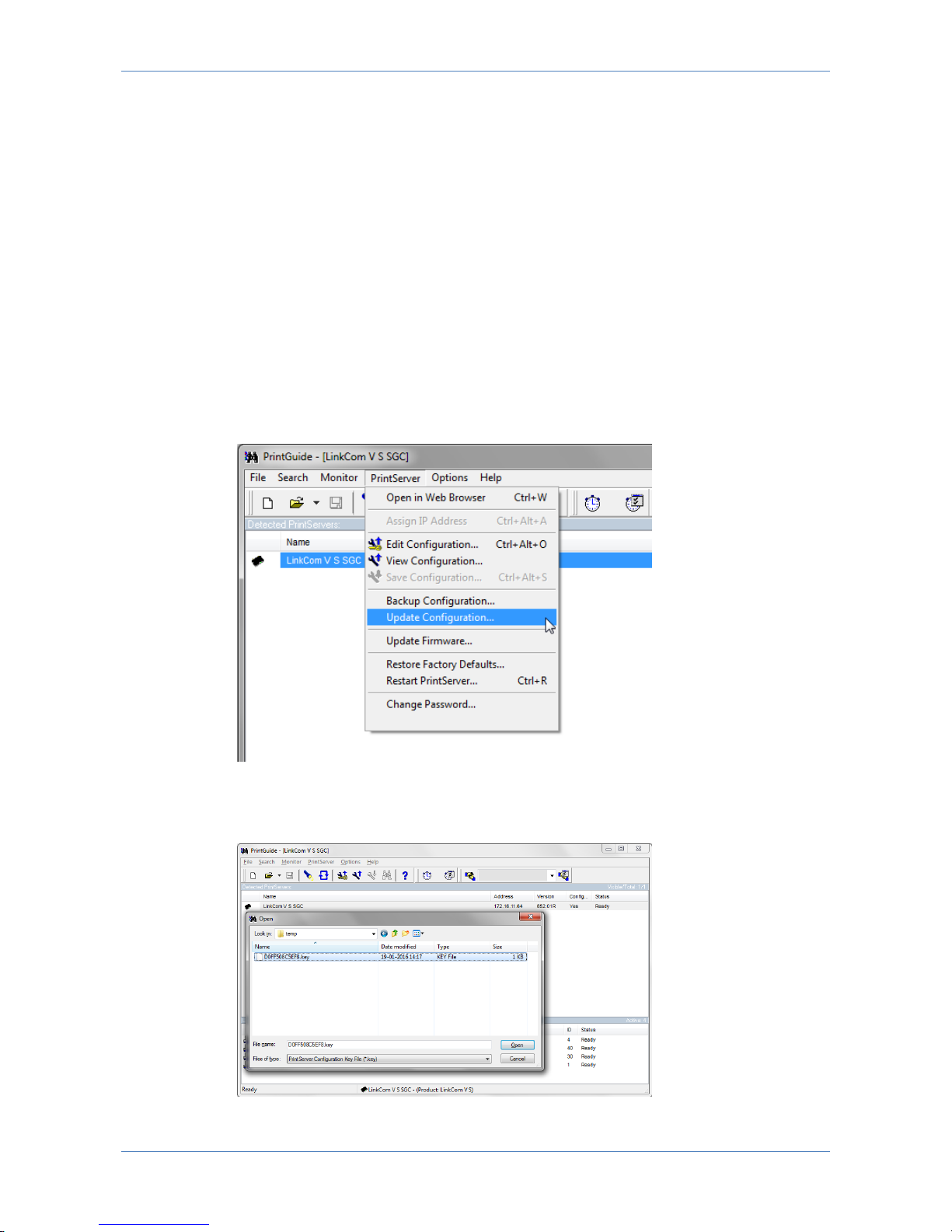
LinkCom 5 User Manual
Page 72
12 Using PrintGuide to add new features
New features purchased after the initial purchase can be enabled via PrintGuide.
12.1 Prerequisites
An updated license key that covers additional features is issued by MPI Tech.
The LinkCom 5 PrintServer must be online and available through PrintGuide.
The PrintGuide version used must be S42 065.490 or newer.
12.2 Installing new features
Open PrintGuide, and highlight the LinkCom 5 PrintServer to be feature
updated.
Go to menu “PrintServer”, “Update Configuration”.
Change file type to “PrintServer Configuration key file” and browse to the
location of your feature *.key file
Select file, and click Open.
Page 73

LinkCom 5 User Manual
Page 73
Confirm downloading key file.
Save changes and accept to restart the PrintServer.
Upon restart the new features will be available and can be configured.
Page 74
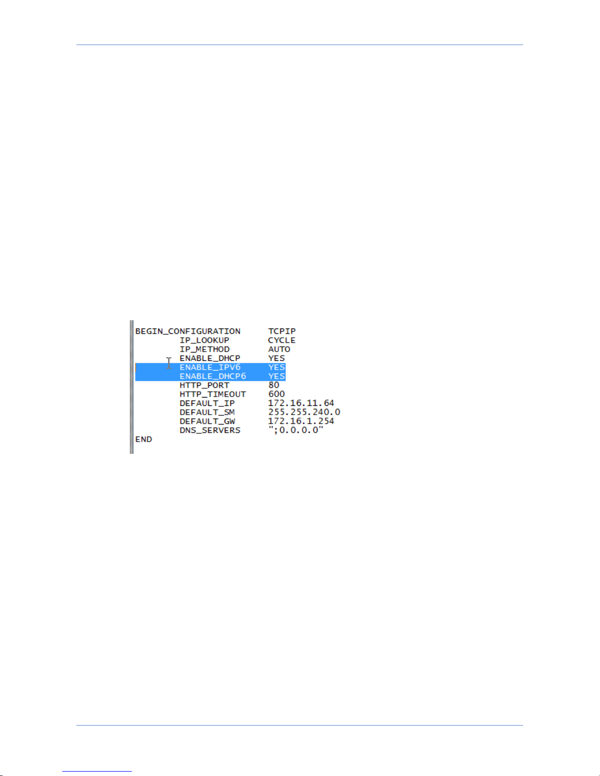
LinkCom 5 User Manual
Page 74
13 Enabling/disabling hidden features
Some LinkCom 5 options cannot be reached from PrintGuide. These settings can
only be changed manually directly in the configuration file. These are called hidden
features
13.1 How to enable/disable options
Any of the hidden options are manipulated the following way:
1. Use PrintGuide to make a configuration backup
2. Open the backup file in a text editor, e.g. Notepad
3. Locate the setting you need to change and change the value
4. Save changes to the configuration file
5. Use PrintGuide to upload the manipulated configuration file to the
PrintServer
6. From PrintGuide save changes and restart the PrintServer
13.2 Disabling IPv6 and DHCPv6
In the backup configuration file, locate the section
“BEGIN_CONFIGURATION TCPIP”
In the default settings IPv6 and DHCP 6 support is enabled.
Disable DHCPv6
Change “ENABLE_DHCP6” from YES to NO
Ordinary IPv6 DHCP support is disabled. The ability to get up an IPv6 address will
be limited to support by IPv6 capable routers. Disabling DHCP6 does not mean that
a static manual IPv6 address can be entered.
Disable IPv6
Change “ENABLE_IPV6” from YES to NO to completely disable IPv6 support.
Page 75
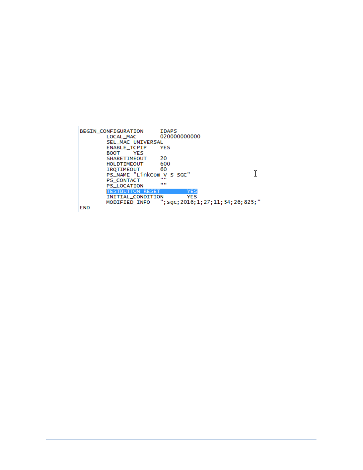
LinkCom 5 User Manual
Page 75
13.3 Test button reset feature
The test button is enabled in the default settings. Pressing the test button holding it
between 8 and 60 seconds will force the PrintServer to reset settings to factory
defaults.
Disable reset to factory defaults via test button
Locate the section “BEGIN_CONFIGURATION IDAPS”
Change TESTBUTTON_RESET value from YES to NO
Save changes.
This change will not disable the ability to print a test page by pressing the test
button.
Page 76
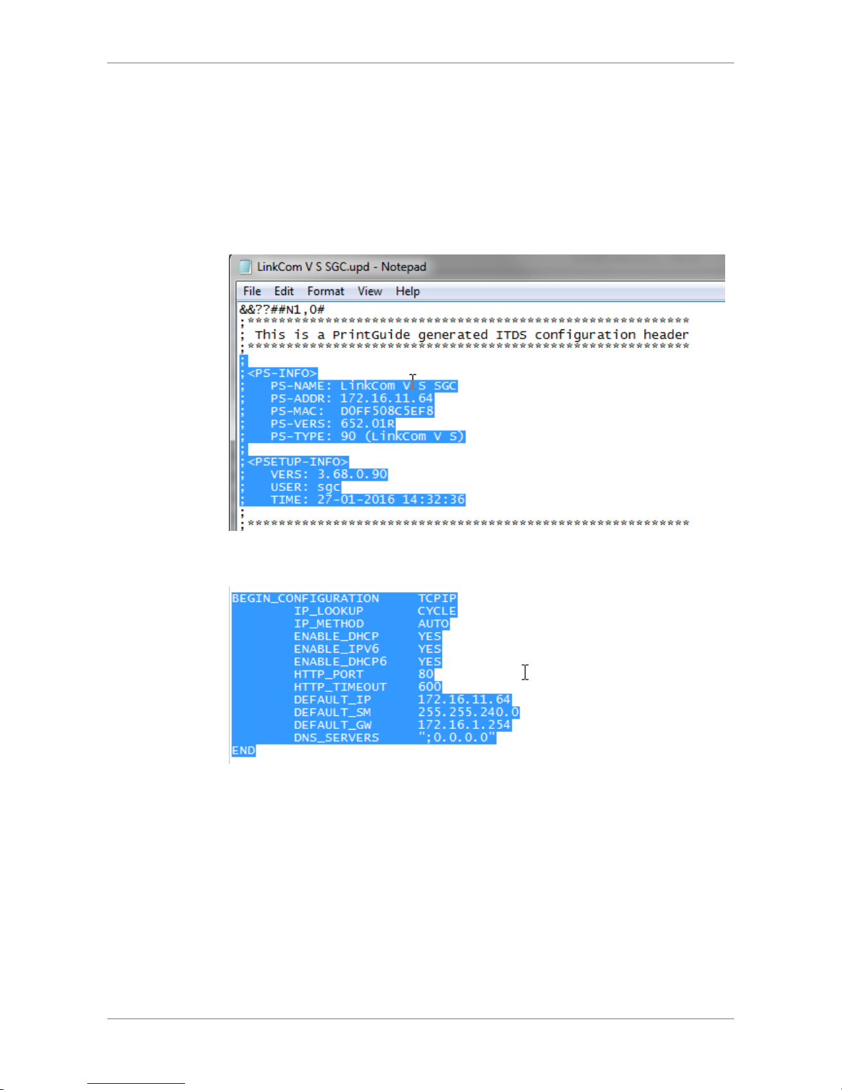
LinkCom 5 User Manual
Page 76
14 Cloning PrintServer settings
It is possible to clone LinkCom 5 PrintServer to multiple units. This sections takes
you through the process.
1. Use PrintGuide to make a configuration backup
2. Open the backup file in a text editor, e,g, Notepad
3. Remove the following sections from the configuration file:
The section that includes the name, MAC address and IP address of the
source PrintSever.
The specific IP address settings for the source PrintServer
Page 77

LinkCom 5 User Manual
Page 77
The sections that hold information about the output printer.
4. Save the configuration file after removing the mentioned sections. Consider
using another filename.
5. Use PrintGuide on the destination LinkCom 5 PrintServer, and import the
cleaned configuration file.
Page 78
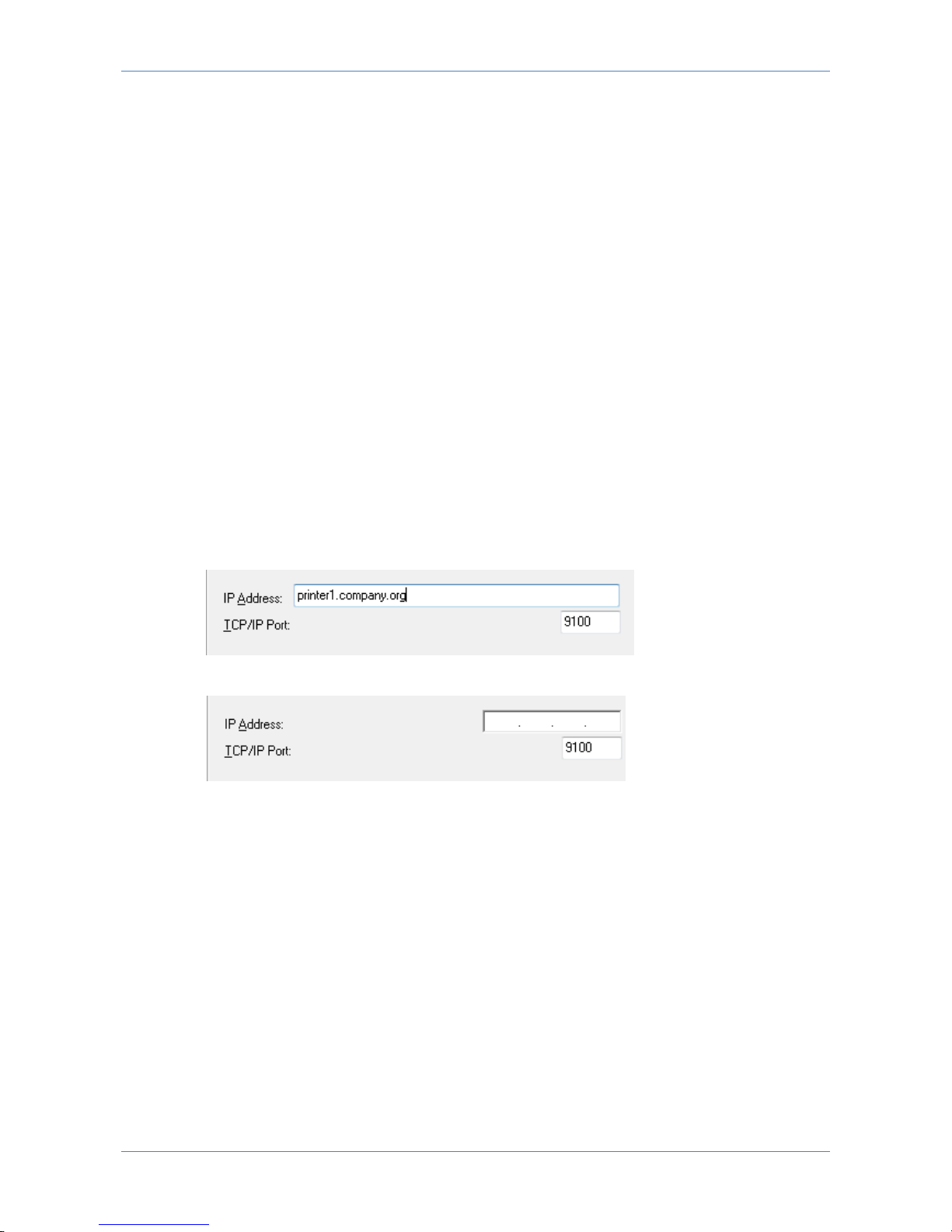
LinkCom 5 User Manual
Page 78
15 Troubleshooting
This chapter addresses known issues and challenges with the PrintServer and how
to work around them.
15.1 Changes to the output printer address are not
applied
Problem:
After assigning a new IP address or a new host name for the output printer (via
PrintGuide), the changes are visible in PrintGuide, but print jobs are not printed on
the intended printer and might be printed on the previously used printer.
This can be caused by the use of an old version of PrintGuide for configuring the
LinkCom 5 PrintServer.
Only use a PrintGuide version that is compatible with LinkCom 5 (version 065.490
or newer). Do not use a PrintGuide version 065.470 or older with LinkCom 5.
With LinkCom 5 a new IP parameter has been included to support output printer
addresses both in the old IPv4 format, as well as IPv6 and DNS formats.
The new PrintGuide accepts the IP input as a string, and interprets the value:
Older versions of PrintGuide only expect and accept an IPv4 address:
In order for the new PrintGuide to be backward compatible and be able to configure
both new and old MPI Tech PrintServers, the new PrintGuide will upload the setting
for the PrintServer and investigate if the old or the new IP representation is
present. If the old way of presenting printer IP addresses is present in the
configuration PrintGuide will expect the PrintServer to be of a type that does not
support the new IP address input format.
Solution:
There are two possible solutions two this issue
Solution 1
Use PrintGuide (version 065.490 or newer) to reset the PrintServer to factory
defaults (Menu “PrintServer”, “Restore Factory Defaults”. Accept a PrintServer
restart. After the power up, the PrintServer needs to be setup again.
Page 79
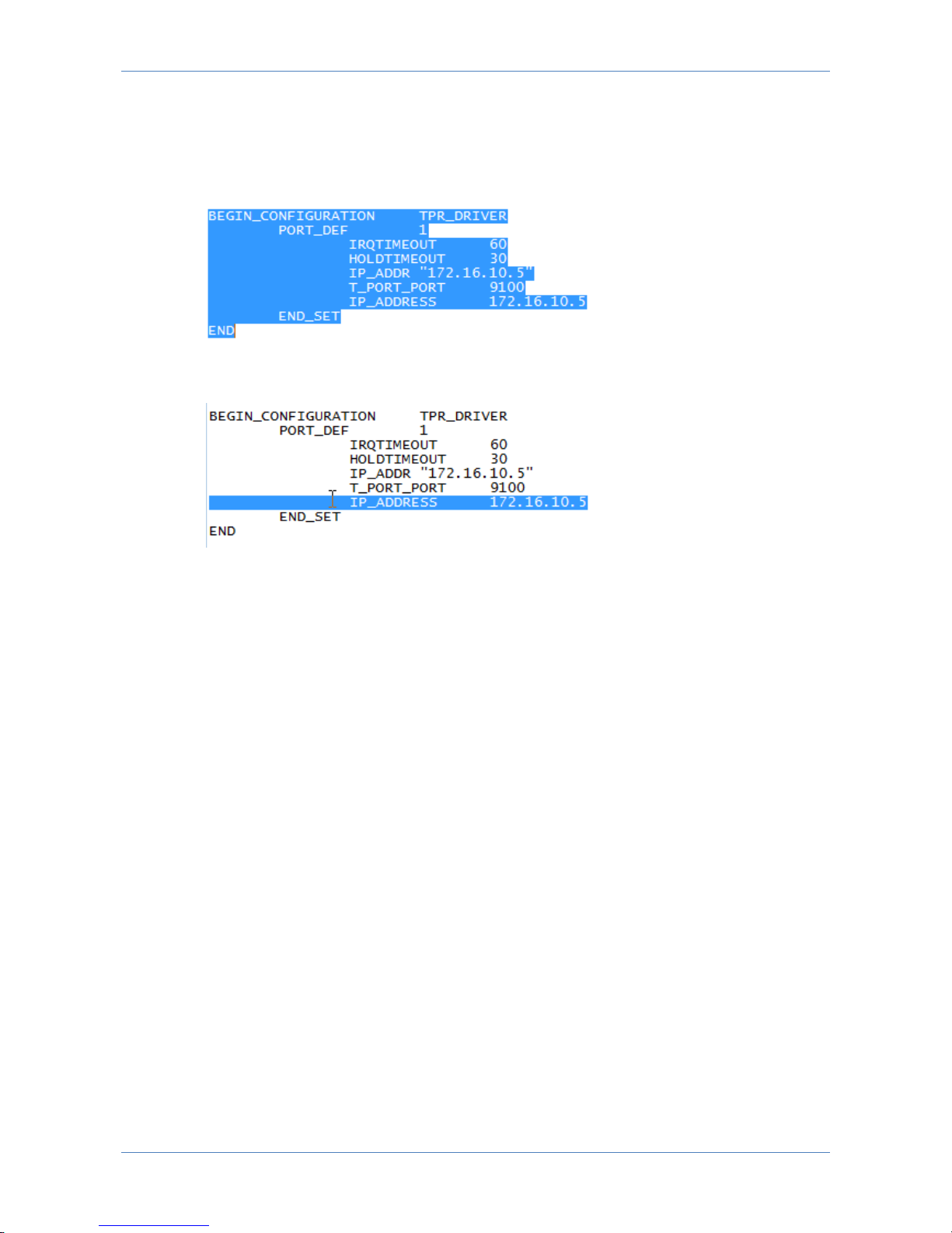
LinkCom 5 User Manual
Page 79
Solution 2
Use PrintGuide (version 065.490 or newer) to back up the PrintServer configuration
before restoring to factory defaults. A xxxxxx.upd file is created.
Open the xxxxxx.upd file in Notepad, and locate the following section:
Remove the entire line starting with IP_ADDRESS (representing the old printer
address format).
Save the updated backup file.
Use PrintGuide to restore to factory defaults, restart the PrintServer and wait for it
to come online again.
Use PrintGuide to upload the corrected settings file. From menu “PrintServer”
,”Update Configuration”.
Accept to import settings and restart the PrintServer.
After the PrintServer restart, printer address settings can again be modified using
PrintGuide.
15.2 LinkCom 5 hangs during a restart
Problem:
In some special cases the LinkCom 5 PrintServer hangs during start up after a
reconfiguration.
The PrintServer will most likely end in a situation where the LAN LED flashes slowly
and continues to do so.
Solution:
Power cycle the PrintServer. It should become available after a restart.
15.3 Not able to see options for Matrix printing
Problem:
Page 80
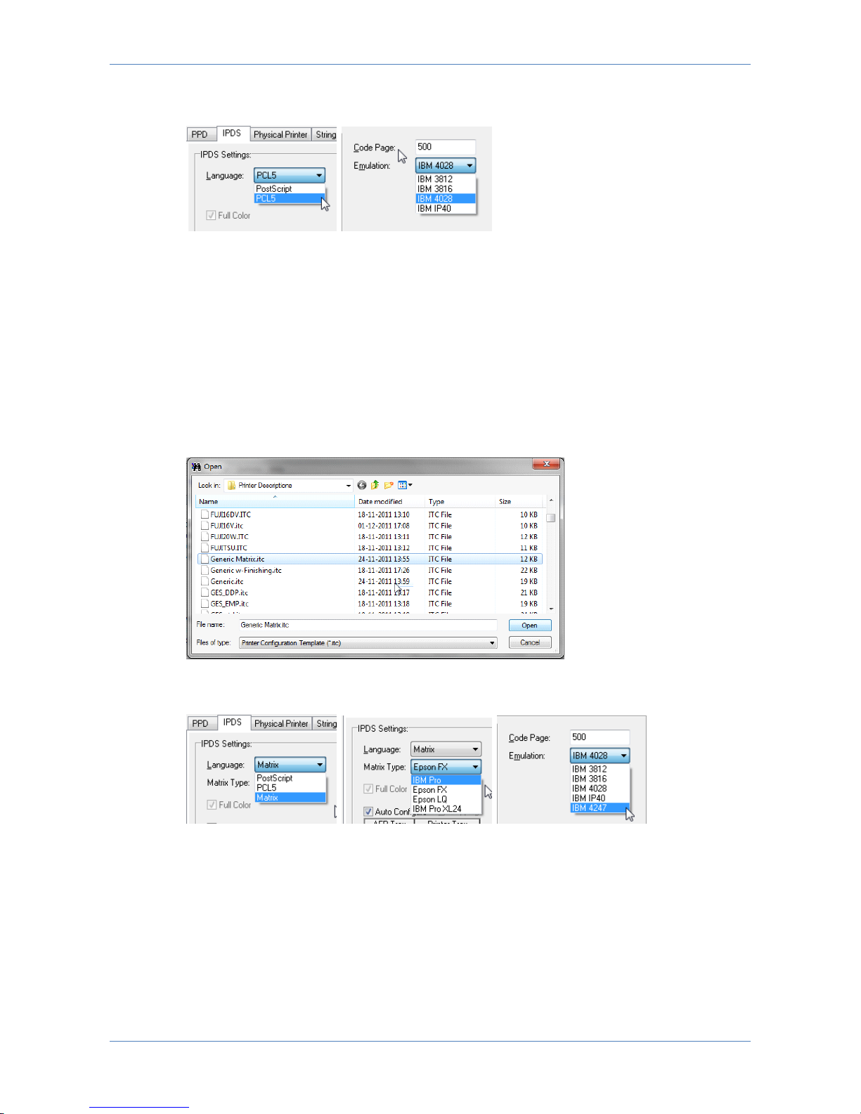
LinkCom 5 User Manual
Page 80
A matrix printer is to be used as output device, but no matrix options are visible for
the LinkCom 5 PrintServer in PrintGuide.
Solution:
Per default LinkCom 5 PrintServer will display PostScript or PCL5 but not Matrix as
possible output transform languages. If Matrix and Epson/IBM Proprinter
emulations are required to be visible and optional in PrintGuide a printer defintion
file for a matrix printer has to be loaded into PrintGuide first.
This is done from the menu “PrintServer”, “Upload Configuration”. Change “Files of
type” to “Printer Configuration Template” and browse to the location of the ITC
files.
Find and select a suitable matrix printer model definition file. It will be applied to
the selected LinkCom 5 PrintServer.
Upon restart of the LinkCom 5 PrintServer, the Matrix options will appear as
optional for the IPDS, DCA and SCS logical printers.
15.4 Not able to see finishing options in PrintGuide
Problem:
Page 81
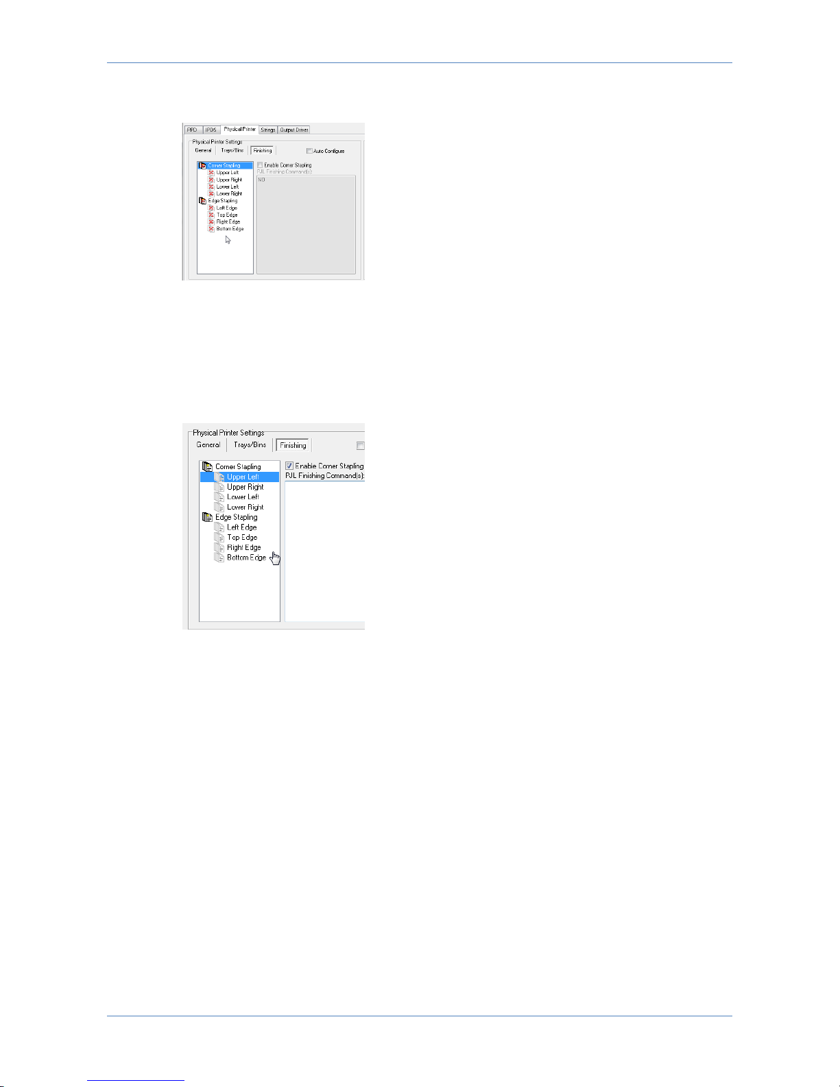
LinkCom 5 User Manual
Page 81
The output printer is a multifunction color printer with finishing options, yet in
PrintGuide finishing options are not visible.
Solution:
Unless the desired options (finishing options, color options, matrix options….) are
defined in the default or loaded printer definition those options will not appear as
options in PrintGuide.
So ensure to load and appropriate printer definition file in PrintGuide. Best is to use
one created for the actual printer if exists.
15.5 DCA Output language keeps returning to
Matrix
Problem:
If the Generic Matrix printer definition has been loaded the DCA Output language
will remain set to Matrix despite changes in PrintGuide.
Solution:
Reset the LinkCom 5 PrintServer to factory defaults. This will clear the conflicting
settings and allow for DCA and ICDS to use PostScript as output language.
Page 82

LinkCom 5 User Manual
Page 82
16 Index
AFP/ICDS
Configure................................................ 28
AFP/ICDS printing ....................................... 57
AFP/IPDS
Configure................................................ 21
AS400 ....................................................... 33
Code page
DCA ....................................................... 35
SCS ....................................................... 41
Configuration page...................................... 18
CPI ........................................................... 41
DCA .......................................................... 34
Configure................................................ 33
DHCPv6
Disable ................................................... 74
Edge to edge .............................................. 30
AFP/ICDS ............................................... 30
AFP/IPDS ................................................ 23
DCA ....................................................... 35
SCS ....................................................... 41
Emulation
IPDS ...................................................... 22
SCS ....................................................... 41
End to end control
AFP/ICDS ............................................... 30
AFP/IPDS ................................................ 23
Factory default ........................................... 18
Finishing
AFP/ICDS ............................................... 31
AFP/IPDS ................................................ 26
DCA ....................................................... 37
SCS ....................................................... 43
Firmware ..................................................... 8
Update ................................................... 70
Full colour
IPDS ...................................................... 23
Hidden features .......................................... 74
Host2Net ............................................... 8, 15
IPDS
Setup ..................................................... 22
IPv6
Disable ................................................... 74
LAN port .................................................... 14
Language
AFP/ICDS ............................................... 29
DCA ....................................................... 35
SCS ....................................................... 40
LED
Combinations .......................................... 67
LAN........................................................ 19
PRT ........................................................ 19
SES ....................................................... 19
Signalling .......................................... 19, 67
License ........................................... 10, 13, 72
Logical printer ............................................ 21
Maintenance ................................................. 8
Margins
AFP/IPDS ................................................ 23
MPL ........................................................... 41
MPP .......................................................... 41
New features .............................................. 72
Offsets
IPDS ...................................................... 23
Options
Disable ................................................... 74
Enable .................................................... 74
Ouput driver
DCA ....................................................... 38
SCS ....................................................... 44
Transparent TP/IP print ............................ 47
Output driver
AFP/ICDS ............................................... 32
AFP/IPDS ................................................ 27
PCL ........................................................... 25
Page 83

LinkCom 5 User Manual
Page 83
Physical printer
AFP/ICDS ............................................... 30
AFP/IPDS ................................................ 24
DCA ....................................................... 35
SCS ....................................................... 41
PJL
AFP/ICDS ............................................... 31
AFP/IPDS ................................................ 26
DCA ....................................................... 37
SCS ....................................................... 43
PostScript .................................................. 25
PPD
AFP/ICDS ............................................... 28
AFP/IPDS ................................................ 21
Printer definition file ...................................... 7
Printer features .......................................... 49
Printer template .................................... 24, 49
PrintGuide......................................... 7, 11, 13
Download ............................................... 20
Getting started ........................................ 20
Search printers ........................................ 20
PrintServer .................................................. 7
PRT port .................................................... 14
PSF/MVS ................................................... 56
PSS ........................................................... 29
Printer profile .......................................... 57
PSS/MVS ................................................... 57
Requirements
Hardware................................................ 11
Host system ............................................ 11
Printer .................................................... 11
Software................................................. 11
SCS .......................................................... 40
Configure................................................ 39
Settings
Clone ..................................................... 76
Strings
AFP/ICDS ............................................... 32
AFP/IPDS ................................................ 26
DCA ....................................................... 37
SCS ....................................................... 43
Transparent TP/IP print ............................ 47
Suppress blank pages
SCS ....................................................... 41
TCP/IP ....................................................... 10
Telnet
DCA ....................................................... 34
SCS ....................................................... 39
Test button ................................................ 18
Reset ..................................................... 75
Transform .................................................... 7
Transparent printing
TCP/IP .................................................... 45
Tray .......................................................... 25
Tray mapping
AFP ........................................................ 23
AFP/ICDS ............................................... 29
SCS ....................................................... 41
Trays
AFP/ICDS ............................................... 31
AFP/IPDS ................................................ 25
DCA .................................................. 35, 36
SCS ....................................................... 42
USB port .................................................... 15
Valid printable area
AFP/IPDS ................................................ 24
Web server ................................................ 49
 Loading...