

Page 1
Echo/Vascular User Manual (15381-C) Page 1 of 46 DCR-00172
Owner’s Manual
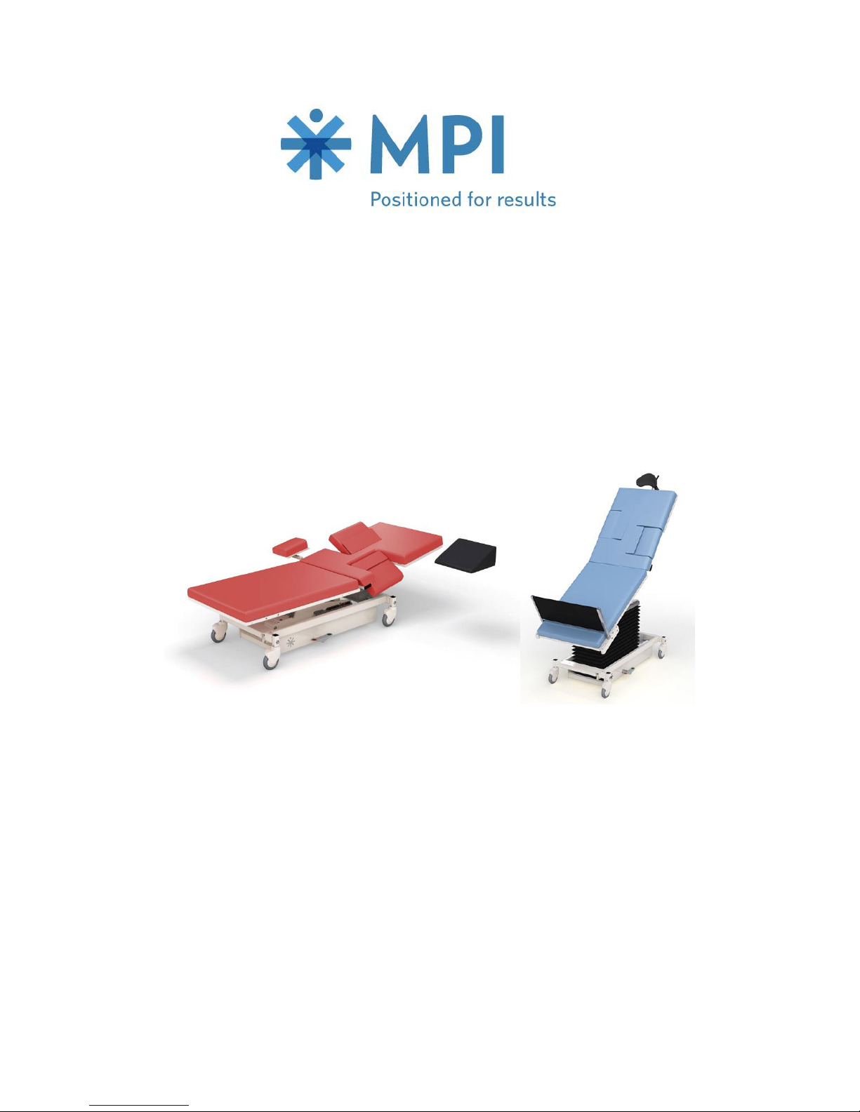
EchoBed® X
VasScan Table™ X
Owner _____________________
Model _____________________
Serial # _____________________
Date _____________________
Page 2

Echo/Vascular User Manual (15381-C) Page 2 of 46 DCR-00172
Table of Contents
Symbols and Definitions ...................................................................... 3
Safety Warnings & Cautions................................................................ 5
Intended Use ....................................................................................... 7
Safety Features ................................................................................... 7
Set Up .................................................................................................. 8
Transport Position................................................................................ 8
Product Illustration ............................................................................... 9
Controls and Indicators ...................................................................... 10
Use Instructions ................................................................................. 14
Powering the Product ..................................................................... 14
Locking the Casters ........................................................................ 15
Hand Control Functions .................................................................. 16
Adjusting Surface Height ................................................................ 16
Adjusting Fowler ............................................................................. 16
Adjusting Trendelenburg ................................................................ 16
Memory Function ............................................................................ 17
Hand Control Lock/Unlock .............................................................. 17
Under-bed Lights ............................................................................ 18
Using the VasScan Table™ X Foot Rest ....................................... 19
Using the Carotid Head Rest .......................................................... 22
Using the Side Rails ....................................................................... 23
Using the Sonographer Extension ................................................. 24
Foley Bag Clip ................................................................................ 25
Storing the Hand Control ................................................................ 25
Under-bed Lights ............................................................................ 25
IV Pole and Holder ......................................................................... 26
Optional Battery .............................................................................. 26
Positioning Wedge .......................................................................... 27
Pediatric Adaptor ............................................................................ 27
Preventative Maintenance ................................................................. 28
Expected Life ..................................................................................... 29
Discard the Unit ................................................................................. 29
Cleaning ............................................................................................. 30
Service Calls ...................................................................................... 32
Troubleshooting Guide ...................................................................... 33
Specifications ..................................................................................... 34
Warranty ............................................................................................ 45
Page 3
Echo/Vascular User Manual (15381-C) Page 3 of 46 DCR-00172
Symbols and Definitions
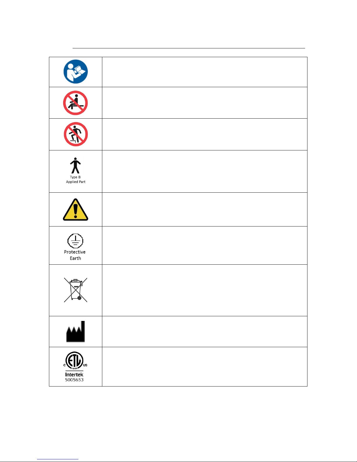
Warning, follow instructions for use. Failure to comply may result in
injury.
Warning, sitting is prohibited. Failure to comply may result in injury.
Warning, standing is prohibited. Failure to comply may result in
injury.
Applied Part complying with specified requirements IEC 60601-1 to
provide protection against electric shock, particularly regarding
allowable patient leakage current.
Warning/Caution, consult accompanying documents.
Any terminal which is intended for connection to an external
protective conductor for protection against electric shock in case of a
fault.
In accordance with the European Directive 2002/96/EC on Waste
Electrical and Electronic Equipment (WEEE), the product must not be
disposed as unsorted municipal waste, but should be collected
separately. Consult your instructional policies and local regulations
regarding disposal. Contact your Medical Positioning, Inc. Service
Representative if additional disposal details are required.
Manufacturer
Agency Mark
Page 4
Symbols and Definitions
Echo/Vascular User Manual (15381-C) Page 4 of 46 DCR-00172
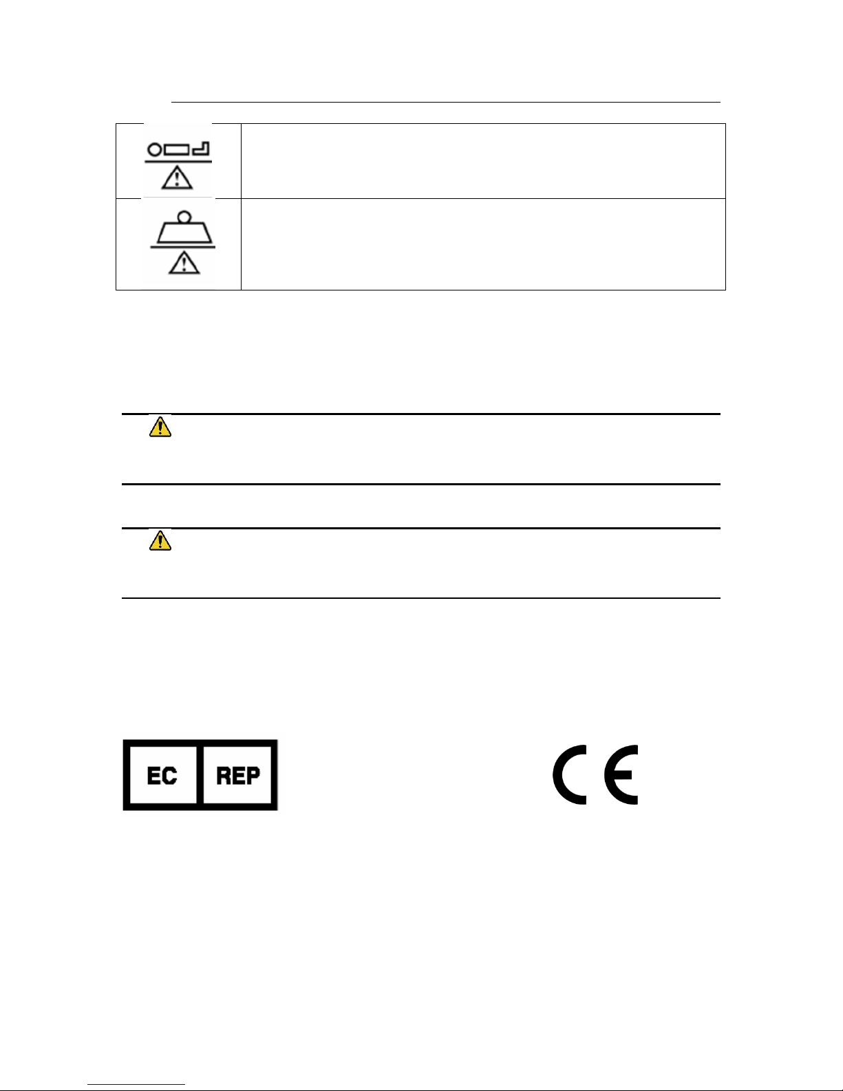
Maximum Patient Weight. Indicates the maximum patient weight
that may be placed on the product.
Safe Working Load. Indicates the sum of the patient weight and
accessories that may be placed on the product.
WARNING / CAUTION / NOTE Definition
The words WARNING, CAUTION, and NOTE carry special meanings and should be
carefully reviewed.
WARNING
Identifies a situation that could result in injury to the patient or caregiver.
CAUTION
Identifies a situation that could result in equipment damage.
Note
Provides special information to make an important instruction more clear.
European Union Representative
MDSS GmbH
Schiffgraben 41
30175 Hannover, Germany
Australian Sponsor
Emergo Australia
Level 20, Tower II
Darling Park
201 Sussex Street
Sydney, NSW 2000
Australia
Page 5

Echo/Vascular User Manual (15381-C) Page 5 of 46 DCR-00172
Safety Warnings & Cautions
WARNING:
Obey these safety instructions to help prevent injury and/or equipment damage:
• Read and understand all warnings in this manual and on the unit itself prior to
use with a patient.
• The device should be operated by trained persons only.
• Authorized and qualified persons will be those who are approved by Medical
Positioning Inc. to repair or modify the product.
• Do not modify this equipment without authorization of the manufacturer.
• Equipment should only be serviced by authorized personnel.
• The procedures in this manual are only manufacturer’s suggestions. The final
responsibility for patient care with respect to this device remains with the
attending physician.
• Do not use in an oxygen rich environment.
• Do not leave patient unattended while using the product.
• To reduce the risk of electric shock, grounding reliability can only be achieved
when the equipment is connected to an equivalent receptacle marked “hospital
only” or “hospital grade”.
• If damage has occurred to the power cord, immediately remove the cord from
service. Failure to do so could result in serious injury or death.
• The battery should be periodically inspected for damage. If damage has
occurred to the battery, immediately remove the battery from service. Failure
to do so could result in serious injury or death.
• Removal of secured covers may increase the risk of electrical shock. Refer
servicing to qualified and approved personnel.
• The potential for electrical shock exists with electrical equipment. Failure to
follow facility protocols may cause death or serious injury.
• Ensure the patient is properly secured prior to using the equipment.
• To reduce the risk of a potential injury, lock casters before using equipment.
• Once the product and patient have been properly positioned for the procedure,
ensure the casters are locked and the hand controller is placed in a safe position
to prevent unwanted contact and unwanted movement of the support surface.
• To reduce the risk of the product becoming unbalanced, always position the
product in the lowest reasonable height when moving.
Page 6

Safety Warnings & Cautions
Echo/Vascular User Manual (15381-C) Page 6 of 46 DCR-00172
• Verify the area around the product is free of impediments before operating to
prevent injury or equipment damage.
• Keep hands and feet clear from beneath the patient surface when lowering
surface height or making positioning adjustments in order to avoid possible
injury.
• Keep hands and feet clear of the scissor lift mechanism when operating or
making positioning adjustments in order to avoid possible injury.
• Keep hands clear of the fowler section hinges during operation to avoid possible
injury.
• Sitting at the end of the patient surfaces can result in device instability. Do not
allow a patient to sit at the head end of the patient surface.
• The footboard should be used for steep reverse Trendelenburg positions to
ensure patient stability.
• Protect vinyl upholstery from sharp objects and abrasion to avoid damage.
• Always read manufacturer’s instructions and warnings before using any cleaning
product or disinfectant. Refer to instructions located in this manual for vinyl
cleaning recommendations.
• Substances such as imaging gels and alcohol will not damage the vinyl surface
when immediately removed. Extended exposure for longer than a few minutes
can damage the top coat and will eventually discolor vinyl.
• Do not use abrasives to clean painted surfaces.
• It is recommended that the product be cleaned between patients; please follow
your facility’s documented policy.
• Keep this manual available for future reference.
• If the product is used adjacent to other electrical equipment, observe the
product and the other electrical equipment to ensure they operate as intended.
• Failure to latch Drop Sections may result in patient injury. Verify Drop Sections
are locked in position before and after use.
• Verify the head rest is secure prior to using the product.
• Verify the side rails are secure prior to using the product and after each side rail
adjustment.
• Do not exceed the weight capacity of the product.
Page 7

Echo/Vascular User Manual (15381-C) Page 7 of 46 DCR-00172
Intended Use
This product is intended to be used in an environment where ultrasound and other such
diagnostic equipment is present, including hospitals, outpatient facilities, and doctor’s
offices. The product is intended to be used by trained healthcare professionals who
possess the ability to operate the product safely. The product’s movements are
controlled both manually and electronically via the product’s hand control.
The product is not intended for use in oxygen rich environments.
Safety Features
• This product is equipped with multiple automated safety features to prevent danger
or damage during use. The entire system is electrically isolated to UL/IEC 60601-1
and CAN/CSA C22.2 No. 601.1 hospital safety standards.
• The actuator assemblies are current overload protected. If overloaded, the
actuators will stop and reset automatically.
• The sealed hand control operates the actuators by directing small amounts of low
voltage D.C. current to the control box. All of the actuator drives are equipped with
internal limit switches which automatically prevent over-extension.
Page 8

Echo/Vascular User Manual (15381-C) Page 8 of 46 DCR-00172
Set Up
The product has been shipped to you in “plug and play” condition. After unpacking the
product, we recommend performing an initial test of your product to ensure that each
function is in correct working order. After reviewing this manual you are ready to begin
using your product.
STEP
ACTION
1
After removing padding and packaging materials locate primary power
supply cord and attach to suitable grounded power outlet.
2
To test actuator function, locate the hand control and depress each
button one at a time. (Depressing multiple buttons simultaneously will
prevent the motor from operating.)
3
If any function does not operate, perform the test procedures listed in
the Troubleshooting Guide.
Transport Position
It is recommended that the patient surfaces be in a horizontal position if the product is
used to transport patients.
Page 9
Echo/Vascular User Manual (15381-C) Page 9 of 46 DCR-00172
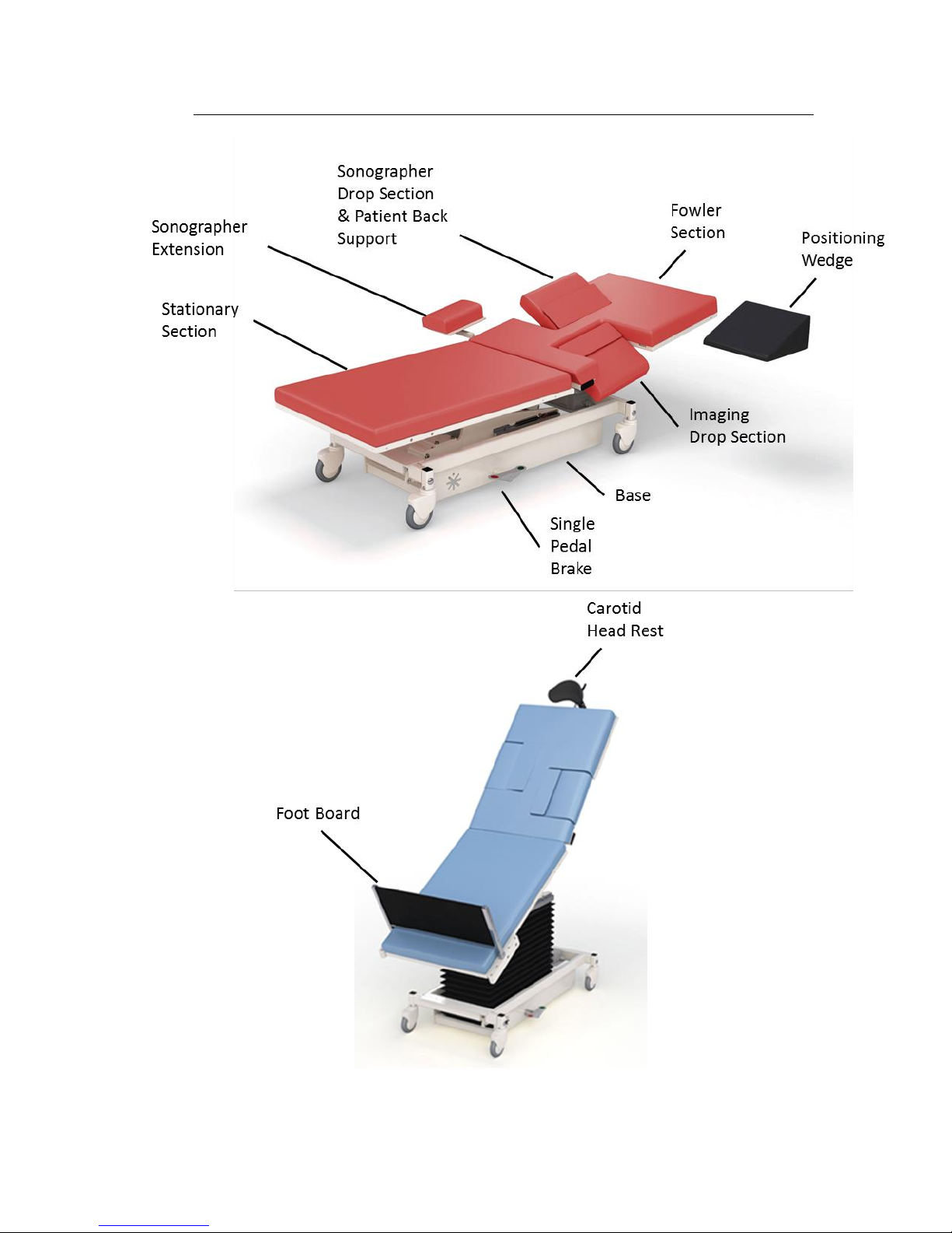
Product Illustration
*Optional features may be shown
Page 10
Echo/Vascular User Manual (15381-C) Page 10 of 46 DCR-00172
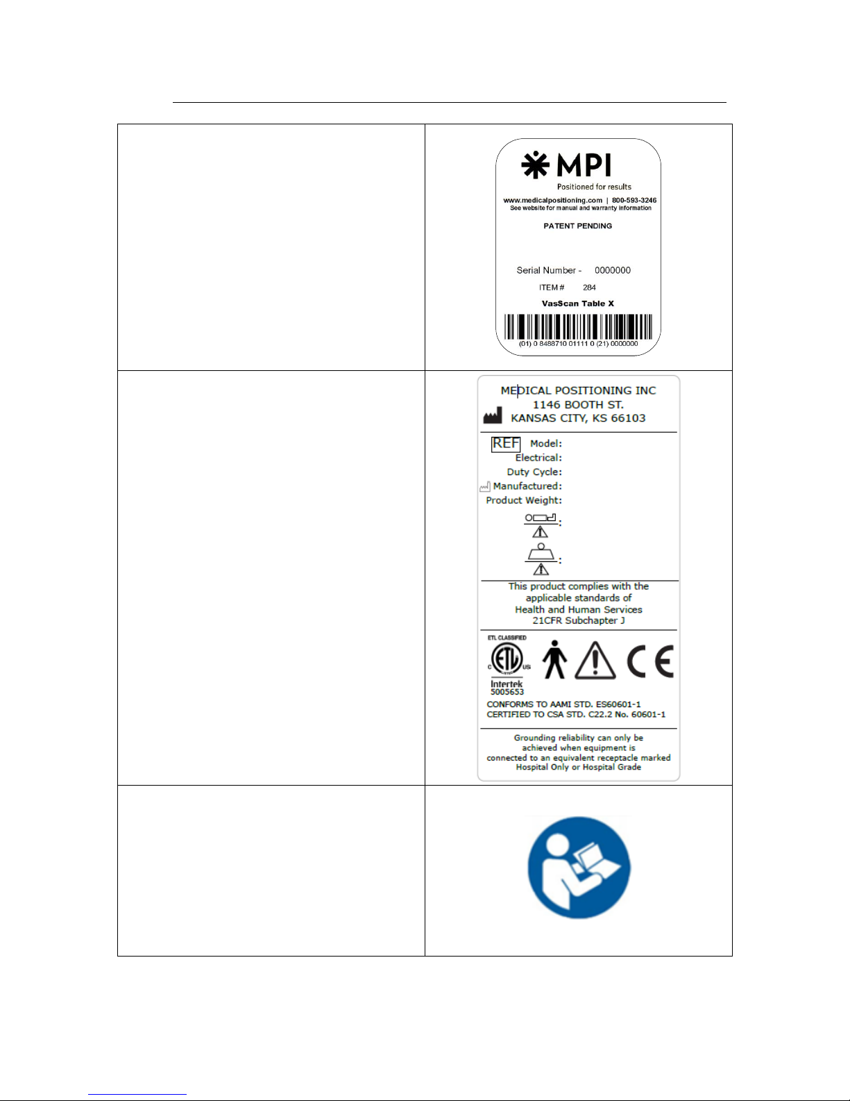
Controls and Indicators
Unique Device Identification Label
• Serial #
• Item #
• Item Description
• Unique Identifier
Certification Label
Refer to Manual Label
Page 11
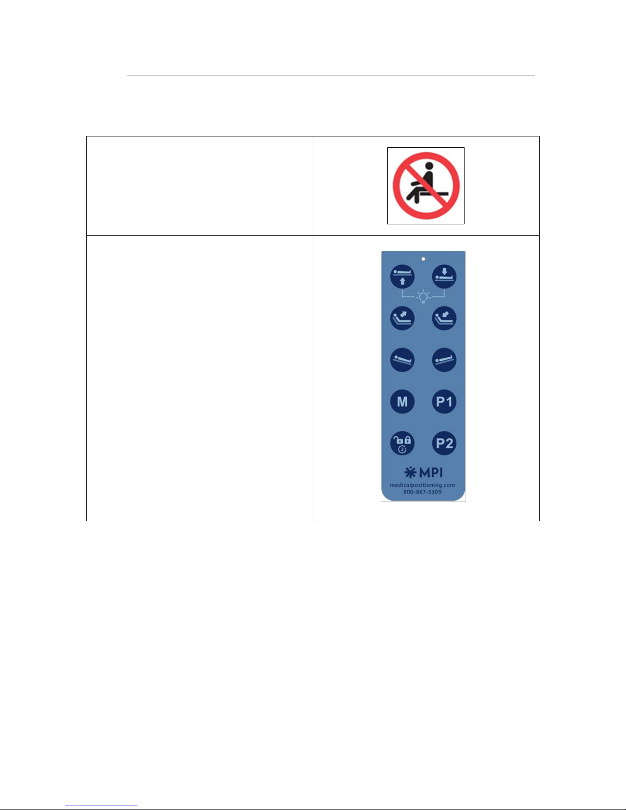
Controls and Indicators
Echo/Vascular User Manual (15381-C) Page 11 of 46 DCR-00172
No Sitting label
Hand Control
Note: Hand control functions will vary
depending on the model purchased. Your
hand control may differ from the images
to the right.
Page 12
Controls and Indicators
Echo/Vascular User Manual (15381-C) Page 12 of 46 DCR-00172
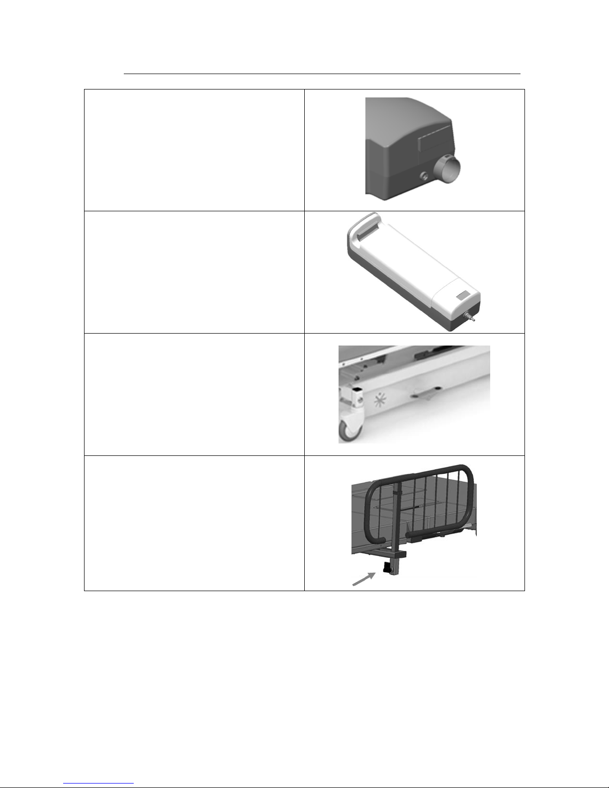
AC Input
Battery
Pedals for Single Pedal Brake
Side Rail Release
Page 13
Controls and Indicators
Echo/Vascular User Manual (15381-C) Page 13 of 46 DCR-00172
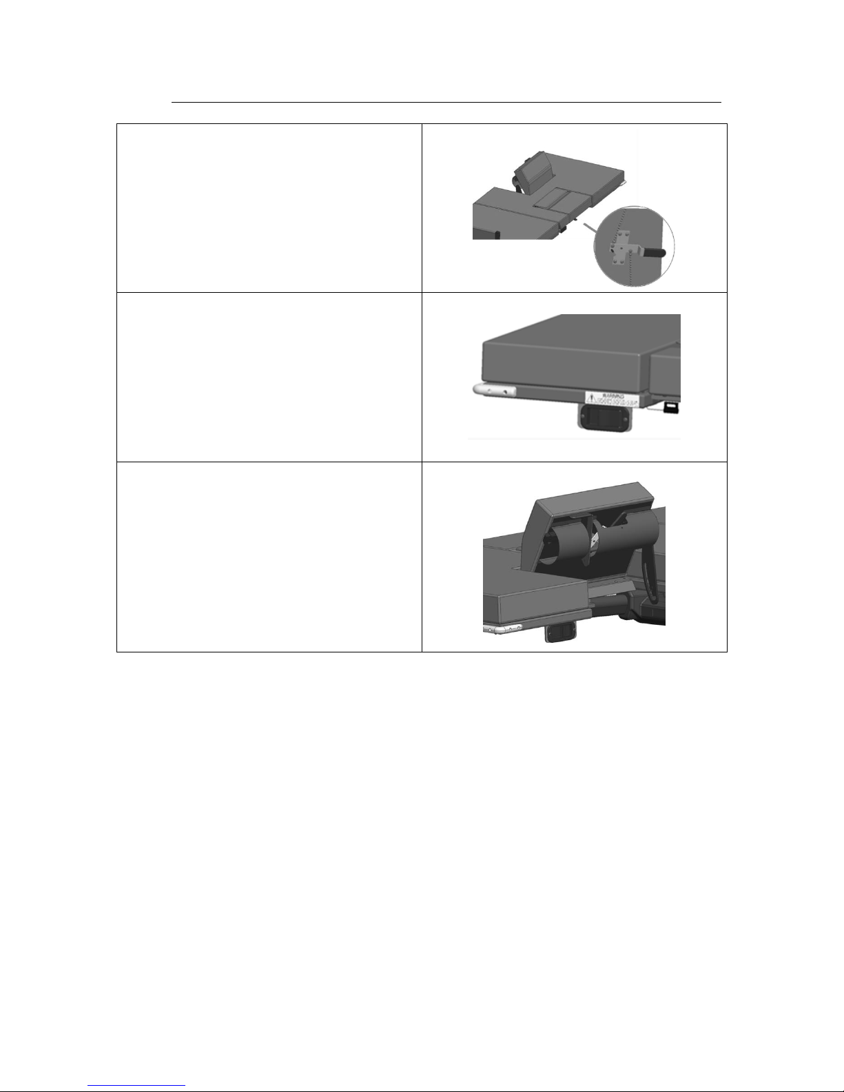
Drop Section Release
Drop Section Remote Release
Back Rest Release
Page 14
Echo/Vascular User Manual (15381-C) Page 14 of 46 DCR-00172
Use Instructions
Powering the Product
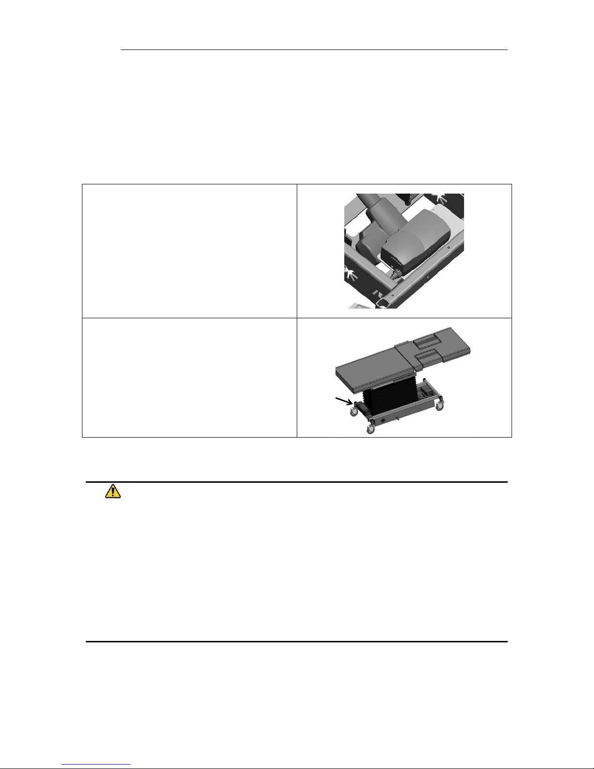
The product can be powered by AC power from a wall outlet or by DC power via the
optional battery. The product is “on” whenever it is plugged into AC power or when a
charged battery is installed. The product should not be positioned in a way that would
make it difficult to remove power by unplugging the AC power cord or removing the
battery.
To apply AC power to the product, attach
the power cord to the AC input located at
the rear of the product.
To apply DC power to the product, install a
battery at the foot end of the product.
Note: The battery may be charged while it
is installed in the product by plugging the
product into AC power.
WARNING
• To reduce the risk of electrical shock, grounding reliability can only be achieved when the
equipment is connected to an equivalent receptacle marked “hospital only” or “hospital
grade.”
• If damage has occurred to the power cord, immediately remove the cord from service.
Failure to do so could result in serious injury or death.
• If damage has occurred to the battery, immediately remove the battery from service.
Failure to do so could result in serious injury or death.
• The battery should be periodically inspected for damage. Replace the battery if necessary.
Page 15
Use Instructions
Echo/Vascular User Manual (15381-C) Page 15 of 46 DCR-00172
Locking the Casters
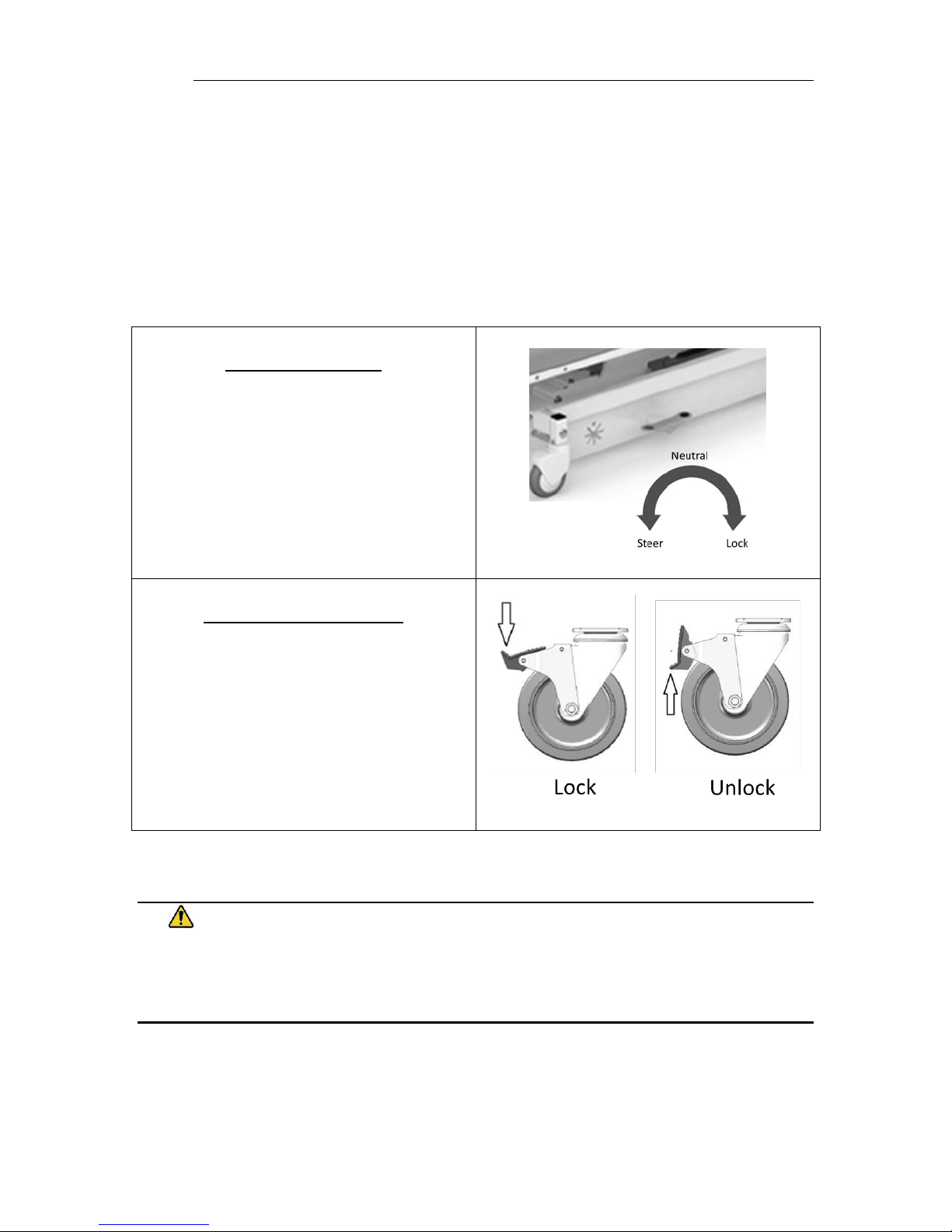
The product may be equipped with total locking casters or individual locking casters.
The total locking casters have 3 functional positions: full swivel, steer, and full lock.
• In the neutral position all four casters may swivel and roll.
• In the steer position the front casters are held in a forward facing orientation
and the rear casters are free to swivel.
• In the lock position all four casters are prevented from both rolling and swiveling.
Single Pedal Braking
Pedals are located on each side of the base
and are used to adjust the caster function.
Individual Locking Casters
The locking tab is located on each caster.
Push down to lock, lift to unlock.
WARNING
• Once the product and patient have been properly positioned for the procedure, ensure the
casters are locked and the hand controller is placed in a safe position to prevent unwanted
contact and unwanted movement of the product surface during the procedure.
Page 16
Use Instructions
Echo/Vascular User Manual (15381-C) Page 16 of 46 DCR-00172
Hand Control Functions
Hand control functions will vary depending on the model purchased. Your hand control
may not include all of the functions listed below.
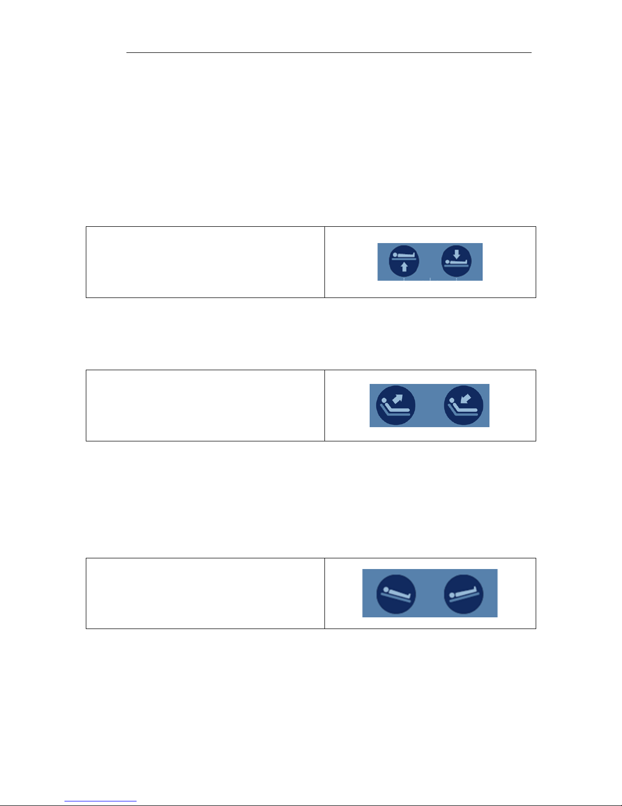
Adjusting Surface Height
The minimum surface height is 19” when the surface is level but will stop at heights
above this value depending on the angle of Trendelenburg or Reverse Trendelenburg.
The limitations are to protect against equipment damage and injury.
Press and hold the applicable hand control
function to adjust the seat height.
Adjusting Fowler
The fowler section may be adjusted between 0° and 65°.
Press and hold the applicable hand control
function to independently adjust the fowler.
Adjusting Trendelenburg
The Trendelenburg / Reverse Trendelenburg angle is limited at various heights in order
to protect against equipment damage and injury. Depending on the product model, the
full range of Trendelenburg / Reverse Trendelenburg will be available between 26” – 30”
of surface height.
Press and hold the applicable hand control
function to independently adjust the
Trendelenburg angle.
Page 17
Use Instructions
Echo/Vascular User Manual (15381-C) Page 17 of 46 DCR-00172
Memory Function
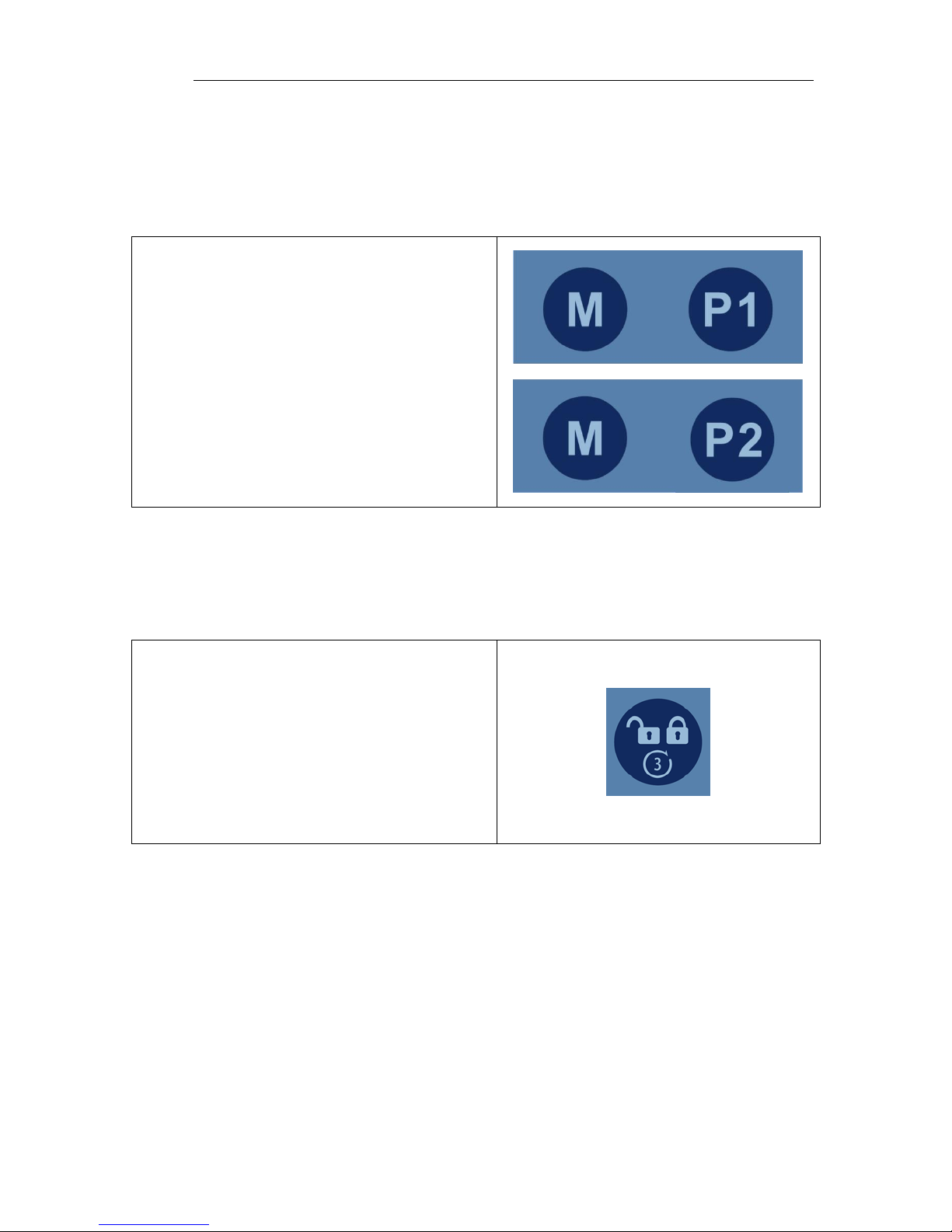
Some product configurations have the ability for the user to set memory positions. The
control box can store two unique positions for buttons P1 and P2. The memory feature
stores the position for height, fowler, and trend.
To set a memory position, press and hold the
“M” button and then simultaneously press
and hold either “P1” or “P2”. The green LED
at the top of the hand control will flash 3
times when the memory position has been
set. Setting a memory function takes
approximately 3-4 seconds.
The memory positions can be reset to new
positions by following the instructions above.
Hand Control Lock/Unlock
The hand control function may be locked during the procedure to prevent unwanted
movement if the buttons are inadvertently depressed.
Press and hold the lock/unlock button for 3
seconds to lock functions. The green LED at
the top of the hand control will light up.
Press and hold the lock/unlock button for 3
seconds to unlock functions. The green LED
at the top of the hand control will turn off.
Page 18
Use Instructions
Echo/Vascular User Manual (15381-C) Page 18 of 46 DCR-00172
Under-bed Lights
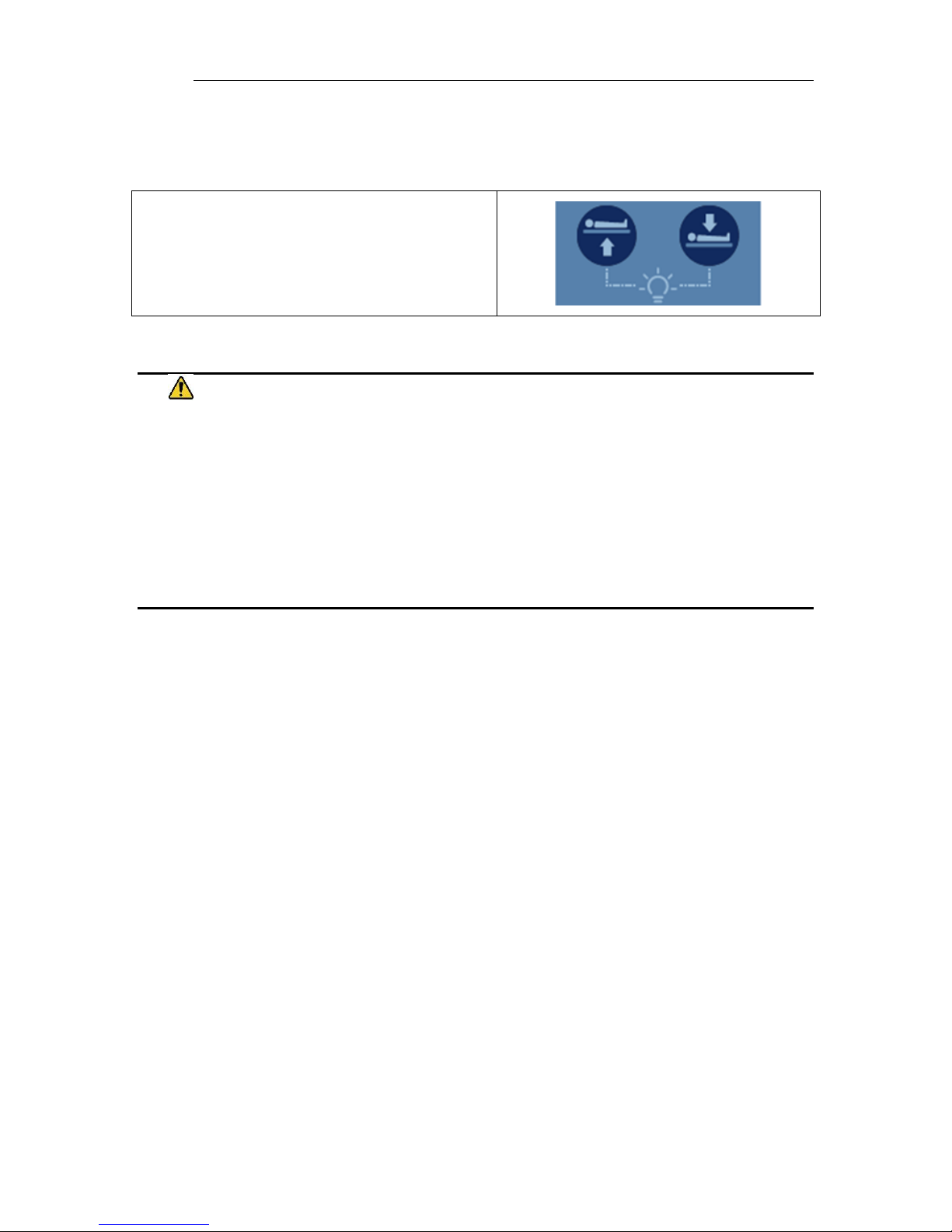
The product may be equipped with optional under-bed lights.
Press both height up-down buttons to turn
on/off the under-bed lights.
WARNING
• Verify the area around the product is free of impediments before operating to prevent
injury or equipment damage.
• Keep hands and feet clear from beneath the patient surface when lowering surface height
or making positioning adjustments in order to avoid possible injury.
• Keep hands and feet clear of the scissor lift mechanism when operating or making
positioning adjustments in order to avoid possible injury.
• Keep hands clear of the fowler section hinges during operation to avoid possible injury.
Page 19
Use Instructions
Echo/Vascular User Manual (15381-C) Page 19 of 46 DCR-00172
Using the VasScan Table™ X Foot Rest
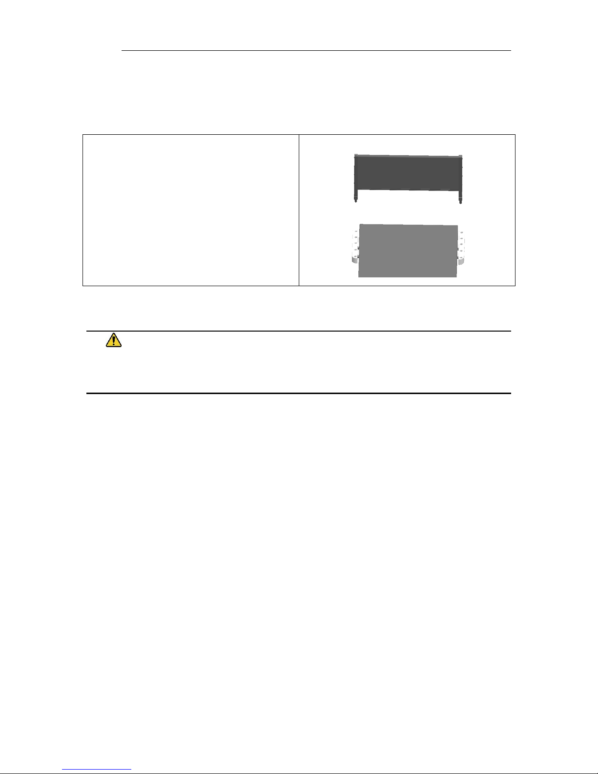
The VasScan Table™ X is equipped with a foot rest used during procedures requiring a
reverse Trendelenburg position.
The foot rest plugs into the receiving block
located on the stationary section. The foot
rest height can be adjusted by
approximately 3” increments.
WARNING
• The footboard should be used for steep reverse Trendelenburg positions to ensure patient
stability.
Page 20
Use Instructions
Echo/Vascular User Manual (15381-C) Page 20 of 46 DCR-00172
Using the Imaging Drop Section
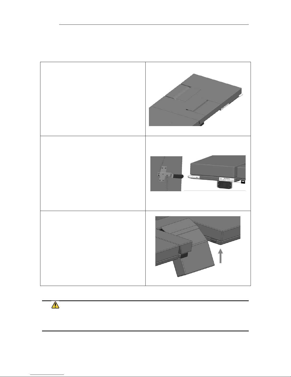
The imaging drop section is located on the fowler section to allow ergonomic
sonographer access to the patient.
Location of Imaging Drop Section
To open the drop section, pull the handle
to release drop section latches.
Or
Use the remote release located on the
opposite side of the support surface.
To close the drop section, lift up on the
drop section up until latches engages.
WARNING
• Failure to latch Drop Sections may result in patient injury. Verify Drop Sections are locked in
position before and after use.
Page 21
Use Instructions
Echo/Vascular User Manual (15381-C) Page 21 of 46 DCR-00172
Using the Sonographer Drop Sections
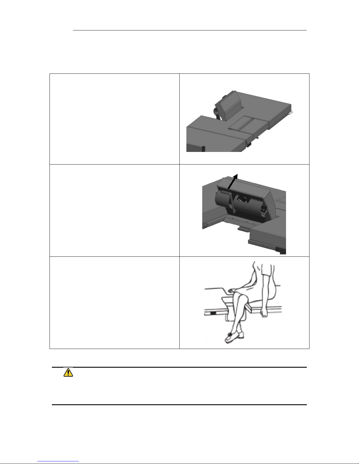
The sonographer drop section allows right handed scanners to get closer to the patient.
It can also be adjusted to act as a patient back rest.
To use the sonographer drop section as a
back rest pull up on the drop section until
it locks into position. There are two back
rest positions to choose from.
To lower from the back rest position, pull
on the handle to release the back rest lock.
Hold the handle while lowering the drop
section until it returns to its stored
position.
To open the sonographer drop section for
better patient access, pull the handle to
release the drop section latches. The
sonographer may be seated as shown
during scanning.
To close the drop section, lift up on the
drop section up until latches engages.
WARNING
• Failure to latch Drop Sections may result in patient injury. Verify Drop Sections are locked in
position before and after use.
Page 22
Use Instructions
Echo/Vascular User Manual (15381-C) Page 22 of 46 DCR-00172
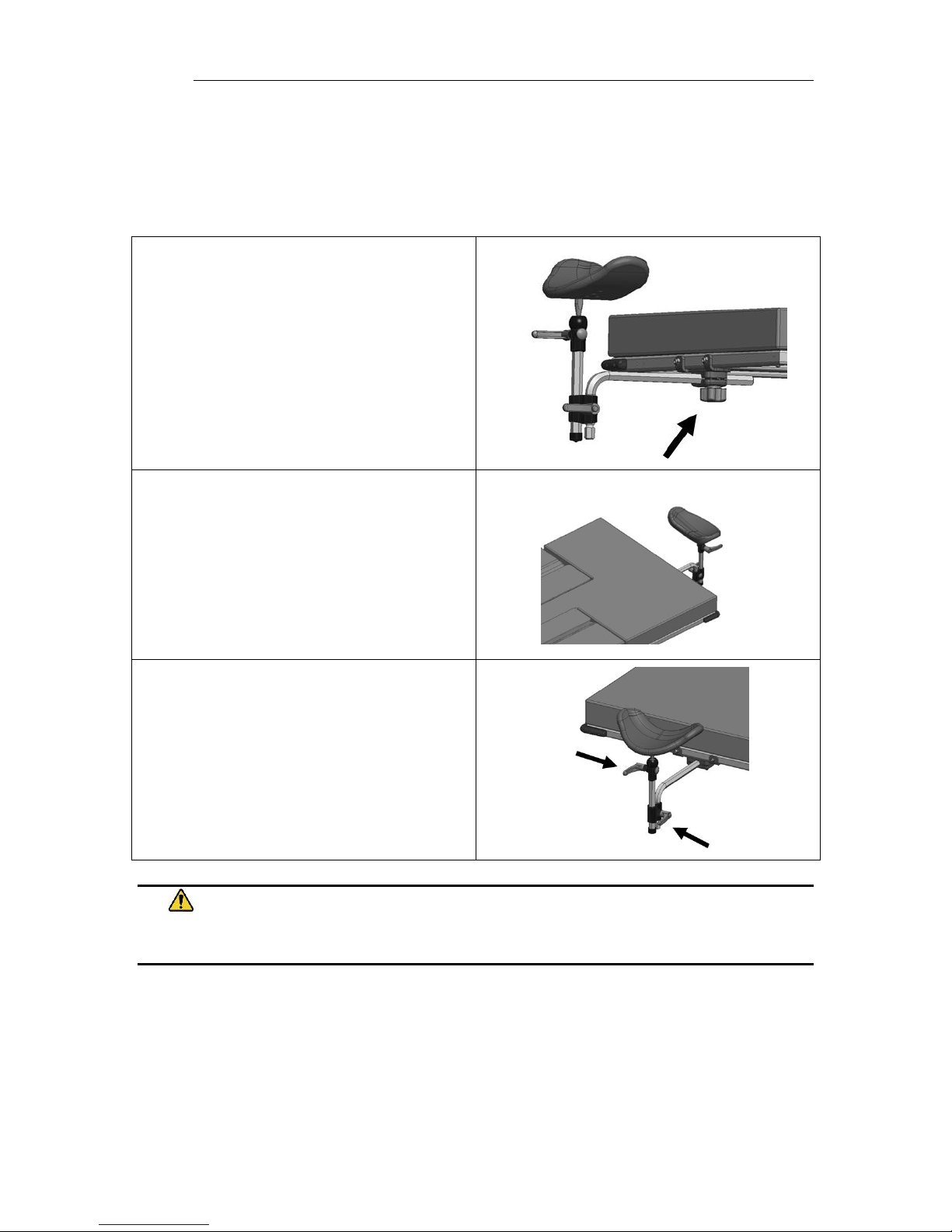
Using the Carotid Head Rest
The product may be equipped with an optional head support to provide better access
during carotid artery scanning. Prior to using the head support the mounting brackets
must be installed at the head end of the product.
The head rest mount is located
underneath the head end of the fowler
section.
Install the head rest and adjust the
location. Tighten the knob on the head
rest mount to secure.
Adjust the height and orientation of the
head rest using the two control knobs.
Tighten to secure.
WARNING
• Verify the head rest is secure prior to using the product.
Page 23
Use Instructions
Echo/Vascular User Manual (15381-C) Page 23 of 46 DCR-00172
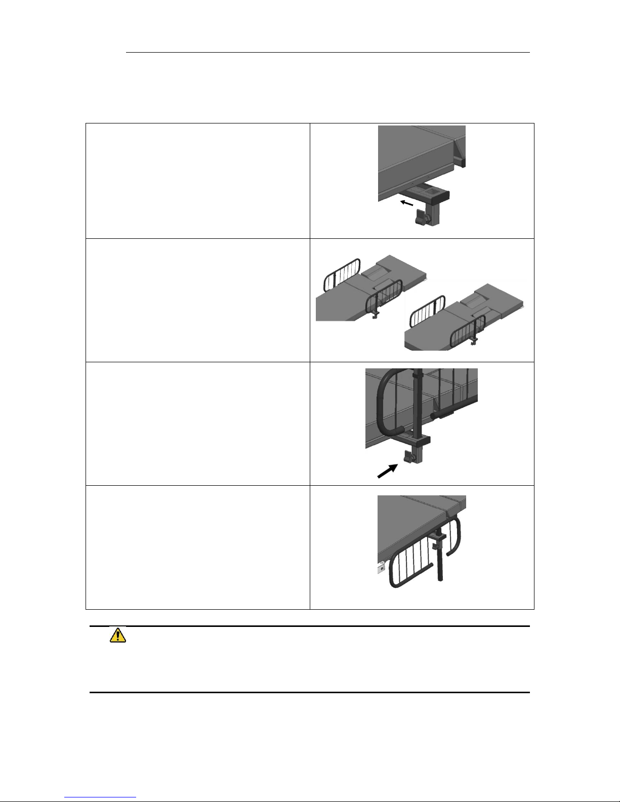
Using the Side Rails
The product may be equipped with optional side rails.
The side rail brackets are stored under the
support surface when not in use and are
pulled out to attach the side rails.
The side rails may be oriented in multiple
directions depending on the access
required for the procedure.
The side rails must be locked in place by
the locking pins.
The side rails may be lowered or removed
by pulling on the release levers.
WARNING
• Verify the side rails are secure prior to using the product and after each side rail
adjustment.
Page 24
Use Instructions
Echo/Vascular User Manual (15381-C) Page 24 of 46 DCR-00172
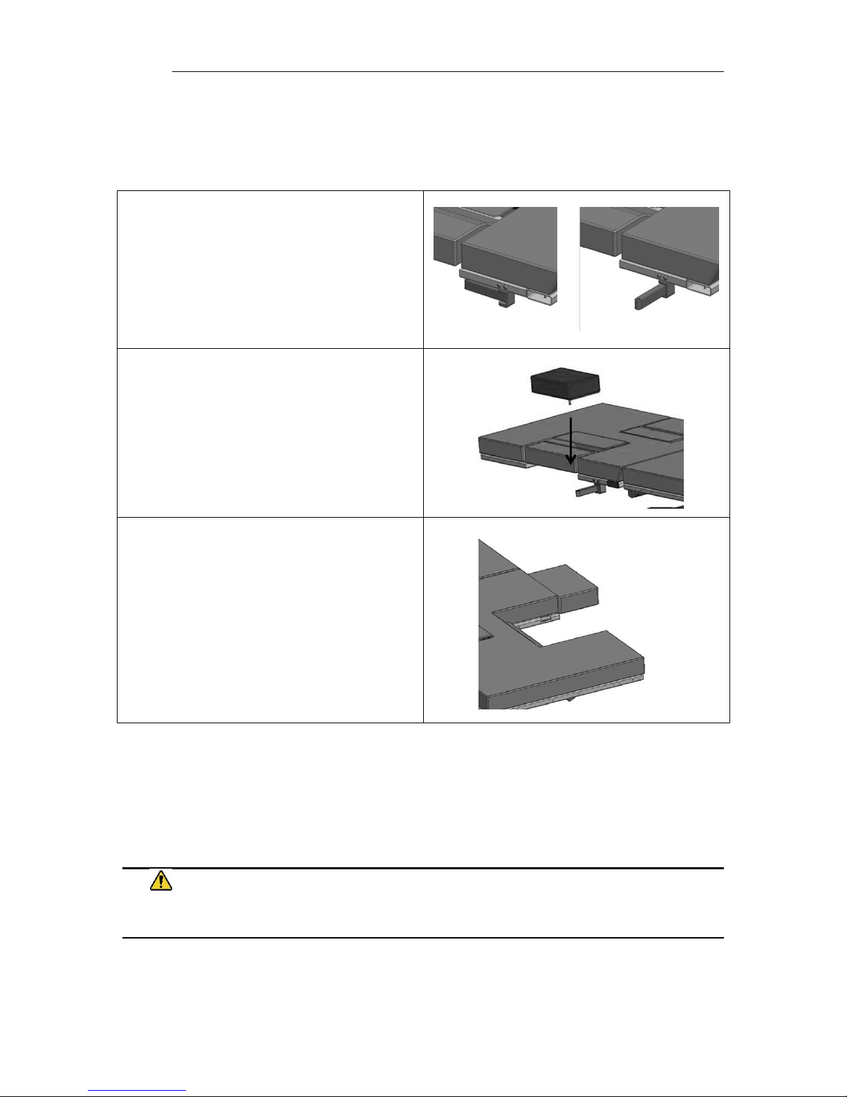
Using the Sonographer Extension
The product may be equipped with an optional sonographer seat extension. This seat
extension allows for a larger seating area for right handed sonographers.
The sonographer seat extension bracket is
stored under the support surface when
not in use and is pulled out to attach the
sonographer’s extension.
The sonographer seat extension is inserted
into the bracket and should fit snugly
against the upholstery.
The sonographer drop section should be
open to provide the maximum seating
area for the sonographer.
Note: When using the sonographer extension the combined weight of the patient and
sonographer shall not exceed the maximum capacity of the product.
Note: The product should be positioned at the lowest reasonable height when using the
sonographer’s extension to ensure maximum stability.
WARNING
• Do not exceed the weight capacity of the product.
Page 25
Use Instructions
Echo/Vascular User Manual (15381-C) Page 25 of 46 DCR-00172
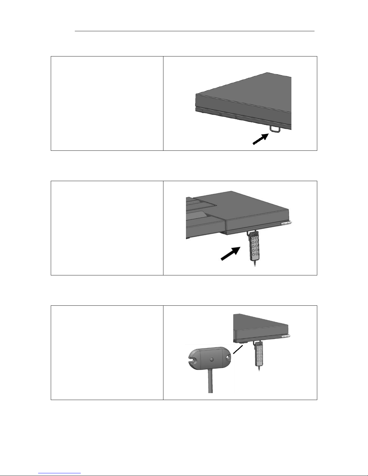
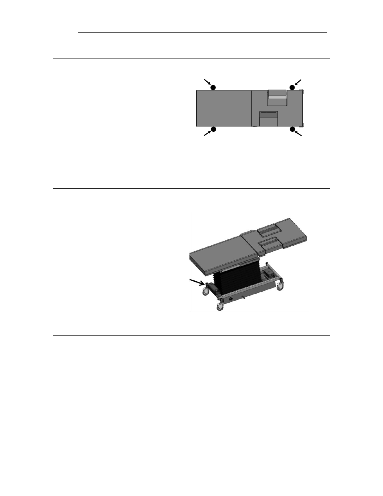
Foley Bag Clip
The product may be equipped with
a hook for hanging a Foley bag.
Storing the Hand Control
The hand control may be hung on
the hook located underneath the
support surface. The hook may be
moved to the end user’s
preference.
Note: If the hand control hook is
moved, ensure there is no
interference through the product’s
range of motion.
Under-bed Lights
The product may be equipped with
under-bed lights.
Page 26
Use Instructions
Echo/Vascular User Manual (15381-C) Page 26 of 46 DCR-00172
IV Pole and Holder
The product may be equipped with
an IV pole. Place the IV pole into
the mounting bracket and tighten
the knob to secure the IV pole to
the product.
The mounting bracket may be
located approximately in the
locations shown.
Optional Battery
The product may be equipped with
an optional battery. The battery
may be charged by plugging in the
product to AC power or by
removing the battery and charging
it on an external charging station.
To remove the battery pull the
release latch and lift the battery.
Note: The lifting capacity of the
product is reduced while on battery
power. The product will only lift a
500lb patient from the minimum
height.
Page 27
Use Instructions
Echo/Vascular User Manual (15381-C) Page 27 of 46 DCR-00172
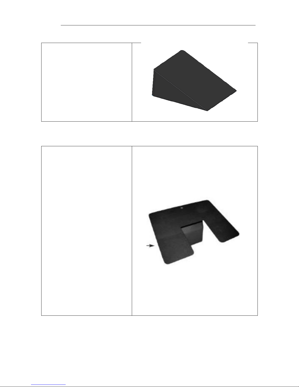
Positioning Wedge
The positioning wedge may be
used to support the patient at a
desired angle.
Pediatric Adaptor
The product may be used with a
pediatric/geriatric adaptor. To
install use the following steps:
1. Lower the Drop Section
2. Remove the non- pinch
closure flap by grasping one
side of the flap and gentle
separating the hook and
loop fastener.
3. Position the adaptor locator
flanges within the imaging
area.
4. Remove the adaptor when
not needed.
5. With the drop-section
lowered, align the top edge
of the non-pinch closure
flap, (within the access
cavity) with the top edge of
the support surface.
6. Press the hook and loop
attachment strips together.
Page 28

Echo/Vascular User Manual (15381-C) Page 28 of 46 DCR-00172
Preventative Maintenance
The following Preventative Maintenance should be performed at a minimum annually.
If any of these checks fail, repair or replace the part as applicable.
• Visually inspect all mechanical assemblies and moving parts on the product
ensuring smooth, steady operation.
• Visually inspect all fasteners (bolts, nuts, screws, etc.) to ensure all are fully
installed. Tighten as necessary.
• Visually inspect all electrical cables and wires for signs of abrasion or other
damage. If damaged, replace.
• Visually inspect all electrical connections to ensure they are fully and properly
connected. Reconnect as necessary.
• Visually inspect the hand control. If damaged, replace.
• Visually inspect the lifting mechanism shroud during raise and lowering. Adjust
or replace if necessary.
• Operate all latch mechanisms to ensure proper engagement of latch into
receiver. Adjust if necessary.
• Operate all motors to ensure full extension, retraction and correct operation.
The motors are permanently lubricated and require no additional lubrication.
• Operate the braking system to ensure proper engagement of the wheel and
swivel lock mechanism. Replace as necessary.
• Operate all accessories to ensure proper attachment and operation. Tighten,
adjust or replace if necessary.
• Remove the seat cover and visually inspect and operate all mechanical and
electrical assemblies as described above.
• Visually inspect the battery for damage. Replace the battery if necessary.
• Unauthorized modification of this product voids any applicable warranty.
WARNING
• No modification of this equipment is allowed.
• Equipment should only be serviced by authorized personnel.
• Removal of secured covers may increase the risk of electrical shock. Refer servicing to
qualified and authorized personnel.
• The potential for electrical shock exists with electrical equipment. Failure to follow facility
protocols may cause death or serious injury.
Page 29

Echo/Vascular User Manual (15381-C) Page 29 of 46 DCR-00172
Expected Life
The expected life of the product is 7 years of normal use. Some components may have a
shorter life and require replacement.
Note: See Warranty section for warranty information.
Discard the Unit
Upon reaching the end of its useful life the product may be discarded in accordance
with local and federal standards. Recycle when possible.
In accordance with the European Directive 2002/96/EC on Waste
Electrical and Electronic Equipment (WEEE), the product must not be
disposed as unsorted municipal waste, but should be collected
separately. Consult your instructional policies and local regulations
regarding disposal. Contact your Medical Positioning, Inc. Service
Representative if additional disposal details are required.
Page 30

Echo/Vascular User Manual (15381-C) Page 30 of 46 DCR-00172
Cleaning
Plastic and Painted Surfaces
The painted metal and plastic surfaces can be cleaned with normal cleaners and
disinfectant.
STEP
ACTION
1
Clean and/or disinfect with liquid cleaner of choice being careful to
follow label instructions provided with cleaner. (Always test a small area
first to determine suitability of solution)
2
Wipe the surface clean with a damp cloth after applying cleaners and
disinfectant to remove excess residue buildup.
Vinyl
The vinyl upholstered surfaces can be cleaned in one of the following ways:
The preferred method of everyday cleaning is using a soft cloth or sponge with mild
soap and water or disinfectant. Spills and accidents require immediate attention for
best results. When caught quickly, most stains such as grease, blood and felt tip pens
can be wiped right off. Mild soap and water is the preferred method; however, typical
hospital-grade antiseptic wipes work as well. For more stubborn stains, a variety of
concentrated and solvent type cleansers may be used without damaging the surface as
long as they are thoroughly rinsed off with water.
Generally speaking, always start with the mildest cleaning agents first. Never use harsh
powdered abrasive cleansers or steel wool. Products containing bleach, ammonia or
alcohol should be wiped from the surface with a wet cloth after use. Residue from these
products will damage vinyl surfaces.
STEP
ACTION
1
Clean and/or disinfect with liquid cleaner while being careful to follow
label instructions provided with cleaner. (Always test a small area first to
determine suitability of solution)
2
Wipe the surface clean with a damp cloth after applying cleaners and
disinfectant to remove excess residue buildup.
Page 31
Cleaning
Echo/Vascular User Manual (15381-C) Page 31 of 46 DCR-00172
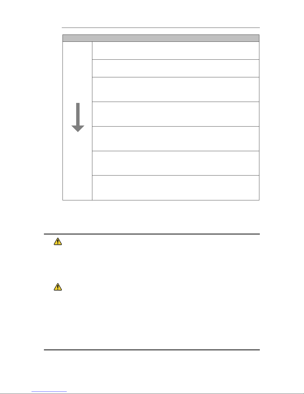
RECOMMENDED MAXIMUM CLEANER TO WATER SOLUTIONS
Mildest
1:1 mix of mild soap and water. Wipe surface with damp cloth with
water only after cleaning.
Straight application of common disinfectants. Wipe surface with damp
cloth with water only after cleaning.
1:1 mix of ammonia and water. Use a soft cotton cloth saturated with
the cleaning material. Wipe surface with damp cloth with water only
after cleaning.
1:4 mix of bleach and water. Use a soft cotton cloth saturated with the
cleaning material. Wipe surface with damp cloth with water only after
cleaning.
1:1 mix of isopropyl alcohol and water. Use a soft cotton cloth saturated
with the cleaning material. Wipe surface with damp cloth with water
only after cleaning.
Straight application of isopropyl alcohol. Use a soft cotton cloth
saturated with the cleaning material. Wipe surface with damp cloth
with water only after cleaning.
Strongest
1:1 mix of acetone and water. Use a soft cotton cloth saturated with the
cleaning material. Wipe surface with damp cloth with water only after
cleaning.
This information is not a guarantee and does not relieve the user from the responsibility
of proper and safe use of the product and all cleaning agents.
WARNING
• It is recommended that the product be cleaned between patients; please follow your
facility’s documented policy.
CAUTION
• Always read manufacturer’s instructions and warnings before using any cleaning product or
disinfectant.
• Substances such as imaging gels and alcohol will not damage the vinyl surface when
immediately removed. Studies have shown that exposure for longer than a few minutes can
damage the top coat and will eventually discolor vinyl.
• Do not use abrasives to clean painted surfaces.
Page 32

Echo/Vascular User Manual (15381-C) Page 32 of 46 DCR-00172
Service Calls
A “Troubleshooting Guide” is included to instruct you in the event of a malfunction. If
you are experiencing any of the following symptoms, this guide may help you quickly
solve the problem. If, after consulting this guide, you are still unable to operate your
product please contact Medical Positioning at 1-800-593-3246. Please have the
following information ready when you call:
1. Model Number or Name of Product
2. Serial Number
3. Date Received
4. Condition When Received
5. Symptom (or problem) Encountered & Result of Troubleshooting Procedure
Complaint Reporting Procedure
In the event of a product malfunction or patient injury, please immediately report the
incident to:
1. __________________________________________________________
(The distributor from whom the product was purchased)
2. Medical Positioning, Inc.
1146 Booth Street
Kansas City, KS 66103
www.MedicalPositioning.com
816-474-1555
800-593-3246 (ECHO)
Page 33

Echo/Vascular User Manual (15381-C) Page 33 of 46 DCR-00172
Troubleshooting Guide
SYMPTOM
PROBABLE CAUSE
SUGGESTION
No Actuator Function
Actuator(s) Not Running.
• Power cord not plugged all
the way into wall receptacle.
• Push power cord securely
into receptacle.
• Power outlet receptacle not
supplying 120 VAC power.
• Check power availability or
plug unit into another
receptacle.
• The power cord may be
separated from the control
box.
• Securely press power cord
into control box.
• Battery may be drained.
• Replace or charge battery.
• Actuator cord may be
unplugged.
• Push actuator cords securely
into actuator receptacle.
• Product was overloaded and
tripped internal fuse in
control box.
• Replace control box.
• Product motion is limited at
certain heights and angles.
• Return the surface to a level
position to restore full range
of motion
• The product will not move
when hand control buttons
are pressed.
• The hand control buttons
may be locked. If the green
LED on the hand control is lit
then press the unlock button
for 3 seconds to unlock the
hand control functions.
Squeaking noises during
operation.
• Actuator pins are not
sufficiently lubricated
• Apply WD40 or similar
lubricant to actuator pins.
WARNING
• Do not modify this equipment without authorization of the manufacturer.
• Removal of secured covers may increase the risk of electrical shock. Refer servicing to
qualified personnel.
• The battery should be periodically inspected for damage. Replace the battery if necessary.
Page 34

Echo/Vascular User Manual (15381-C) Page 34 of 46 DCR-00172
Specifications
Product Models & Attributes
Depending on the country of sale and the options chosen the model number
may be slightly different than what is shown below. For example, the model
number may be followed by a country code such as 201UK or 201EU.
Additionally the model number may be followed by an option code such as
201UK-A or 201-A.
Note: The products covered by this manual are designed to support a 1000lb
static load for emergency situations. The specified maximum patient weight
should be followed for normal usage.
EchoBed® X
ATTRIBUTE
201
222
223
233
Base Width
26”
26”
26”
26”
Base Length
48.5”
48.5”
48.5”
48.5”
Surface Width
30”
30”
30”
30”
Surface Length
80.5”
80.5”
80.5”
80.5”
Surface Height Range
*To top of cushion
19” – 38”
19” – 38”
19” – 38”
19” – 38”
Trendelenburg/
Reverse Trendelenburg
- - 15° / 15°
15° / 15°
Fowler Range
-
0° - 65°
-
0° - 65°
# of Drop Sections
2 2 2
2
Maximum Patient Weight
600lb
600lb
600lb
600lb
Maximum Safe Working Load
625lb
625lb
625lb
625lb
Approximate Product Weight
430lb
440lb
440lb
440lb
Page 35

Specifications
Echo/Vascular User Manual (15381-C) Page 35 of 46 DCR-00172
VasScan Table™ X
ATTRIBUTE
084
284
Base Width
26”
26”
Base Length
48.5”
48.5”
Surface Width
28”
28”
Surface Length
80.5”
80.5”
Surface Height Range
*To top of cushion
19” – 38”
19” – 38”
Trendelenburg/
Reverse Trendelenburg
15° / 30°
15° / 30°
Fowler Range
0° - 65°
0° - 65°
# of Drop Sections
0
2
Maximum Patient Weight
600lb
600lb
Maximum Safe Working Load
625lb
625lb
Approximate Product Weight
420lb
420lb
Page 36

Specifications
Echo/Vascular User Manual (15381-C) Page 36 of 46 DCR-00172
Environmental Conditions
ATTRIBUTE
Range for Use
Range for Storage and
Transport
Ambient Temperature
+0° to 40° C
-10° to +50° C
Relative Humidity
20% to 90% @ 30°C –
not condensing
20% to 90% @ 30°C –
not condensing
Atmospheric Pressure
860 to 1060 hPa
860 to 1060 hPa
Upholstery
ATTRIBUTE
SPECIFICATION
Foam
California Technical Bulletin 117
Vinyl
D.O.T. FAR 25.853 and FMVSS302
Port of NY / Boston F.D. Code
Power Requirements
ATTRIBUTE
SPECIFICATION
Electrical, Product
100–240 VAC, 50/60 Hz, max 5 A
Electrical, Battery Charger
100–240 VAC, 50/60 Hz
Battery Option
24 VDC, 2.9 Ah
Duty Cycle
10%, 2 min. on / 18 min. off
• All electrical circuitry is isolated from chassis.
• Grounding reliability can only be achieved when the equipment is connected to
an equivalent receptacle marked “Hospital Only” or “Hospital Grade.”
• The power cord is to be used for mains disconnection.
• Attached power supply cord set is not allowed to be diverted to other
equipment.
Page 37

Specifications
Echo/Vascular User Manual (15381-C) Page 37 of 46 DCR-00172
Classifications and Standards
ATTRIBUTE
SPECIFICATION
Standards
• IEC 60601-1:2005 + A1:2012
• ANSI/AAMI ES60601-1:2005/(R)2012 and
A1:2012, C1:2009/(R)2012 and A2:2010/(R)2012
• CAN/CSA-C22.2 NO. 60601-1:14
• EN 60601-1:2006 +A11:2011 +A1:2013 +AC:2014
• IEC 60601-1-2:2007
• EN/ISO 14971:2012
Protection against
Electrical Shock
• Class I equipment
• Type B applied part
Degree of protection
against Dust and Fluid
intrusion
• IPX0
Page 38

Specifications
Echo/Vascular User Manual (15381-C) Page 38 of 46 DCR-00172
Applied Parts (in accordance with IEC 60601-1)
• All padded surfaces
• Arm rests
• Foot rest
• Straps
Electromagnetic Emissions Guidance
The product use components that meet the requirements for
IEC 60601-1-2. Other products that are used in the vicinity of the this product
should also comply with this standard. If they do not comply, electromagnetic
interference between the products could cause the products to operate
incorrectly. If problems do occur, contact the product manufacturer(s).
Make sure the product operates correctly when used near other electronic
devices. Portable and mobile radio frequency (RF) communications equipment
can affect electrical equipment.
WARNING
• If the product is used adjacent to other electrical equipment, observe this product and the
other electrical equipment to make sure they operate as intended.
Page 39

Specifications
Echo/Vascular User Manual (15381-C) Page 39 of 46 DCR-00172
Electromagnetic Compatibility
Medical electrical equipment needs special precautions regarding electromagnetic
compatibility (EMC) and needs to be installed and put into service according to the EMC
information provided in this user manual.
Portable and mobile radio frequency (RF) communications equipment can affect
medical electrical equipment.
Guidance and Manufacturer's Declaration - Electromagnetic Emissions
The product is intended for use in the electromagnetic environments specified below. The customer or the
user of the product should assure it is used in such an environment.
Emissions Test
Compliance
Guidance
RF Emissions
CISPR 11
Group 1
Group 2
The product uses RF energy only for its internal function.
Therefore, its RF emissions are very low and are not likely to
cause any interference in nearby electronic equipment. <1>
The product must emit electromagnetic energy in order to
perform its intended function. Nearby electronic equipment may
be affected. <2>
RF Emissions
CISPR 11
Class A
The product is suitable for use in all establishments other than
domestic and those directly connected to the public low-voltage
power supply network that supplies buildings used for domestic
purposes.
Harmonic
Emissions
IEC 61000-3-2
N/A
Voltage
Fluctuations/
Flicker Emissions
IEC 61000-3-3
N/A
Page 40

Specifications
Echo/Vascular User Manual (15381-C) Page 40 of 46 DCR-00172
Guidance and Manufacturer's Declaration - Electromagnetic Immunity
The product is intended for use in the electromagnetic environments specified below. The customer or the
user of the product should assure it is used in such an environment.
Immunity
Test
IEC 60601
Test Level
Compliance Level
Guidance
Electrostatic
Discharge
IEC 61000- 4-2
± 6 kV Contact
± 8 kV Air
± 6 kV Contact
± 8 kV Air
Floors should be wood, concrete, or
ceramic tile. If floors are covered with
synthetic material, the relative
humidity should be at least 30%.
Electrical
Fast Transient/
Burst
IEC 61000-4-4
± 2 kV on power
Supply Lines
± 1 kV on
Input/Output Lines
± 2 kV on Power
Supply Lines
± 1 kV on
Input/Output Lines
Mains power quality should be that of
a typical commercial or hospital
environment
Surge
IEC 61000-4-5
± 1 kV Differential
Mode
± 2 kV Common
Mode
± 1 kV Differential
Mode
± 2 kV Common
Mode
Mains power quality should be that of
a typical commercial or hospital
environment
Voltage Dips, Short
Interrupts,
& Variations on
Power Supply Lines
IEC 61000-4-11
< 5% UT
(95% dip in
UT for 0.5 cycles)
< 40% UT
(60% dip in
UT for 5 cycles)
< 70% UT
(30% dip in
UT for 25 cycles)
< 5% UT
(95% dip in
UT for 0.5 cycles)
< 40% UT
(60% dip in
UT for 5 cycles)
< 70% UT
(30% dip in
UT for 25 cycles)
Mains power quality should be that of
a typical commercial or hospital
environment. If the user of the
product requires continued operation
during mains interruptions, it is
recommended that the product be
powered from an uninterruptible
power supply or a battery.
Power Frequency
Magnetic Fields
IEC 61000-4-8
3 A/m
3 A/m
Power frequency magnetic fields
should be at levels characteristic of a
typical location in a typical commercial
or hospital environment.
NOTE UT is the a.c. mains voltage prior to application of the test level
Page 41
Specifications
Echo/Vascular User Manual (15381-C) Page 41 of 46 DCR-00172
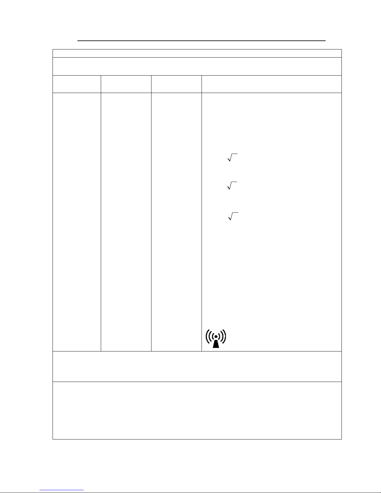
Pd 2,1=
Pd 3,2=
Pd 2,1=
Guidance and Manufacturer's Declaration - Electromagnetic Immunity
The product is intended for use in the electromagnetic environments specified below. The customer or the
user of the product should assure it is used in such an environment.
Immunity
Test
IEC 60601
Test Level
Compliance
Level
Guidance
Conducted RF
IEC 61000-4-6
Radiated RF IEC
61000-4-3
3 Vrms
150 kHz to 80
Mhz
3 Vrms
80 MHz to 2.5
GHz
3 Vrms
3 V/m
Portable and mobile RF communications equipment
should be used no closer to any part of the product,
including cables, than the recommended separation
distance calculated from the equation applicable to
the frequency of the transmitter.
Recommended separation distance
80 MHz to 800 MHz
800 MHz to 2.5 GHz
Where P is the maximum output power rating of the
transmitter in watts (W) according to the
transmitter manufacturer and d is the
recommended separation distance in meters (m).
Filed strengths from fixed RF transmitters, as
determined by an electromagnetic site survey,a
should be less than the compliance level in each
frequency range.
b
Interference may occur in the vicinity of equipment
marked with the following symbol:
NOTE 1 At 80 MHz and 800 MHz, the higher frequency range applies.
NOTE 2 These guidelines may not apply in all situations. Electromagnetic propagation is affected by absorption and reflecti on from
structures, objects and people.
a
Field strengths from fixed transmitters, such as base stations for radio (cellular/cordless) telephones and land mobile radio s, amateur
radio, AM and FM radio broadcast and TV broadcast cannot be predicted theoretically with accuracy. To assess the electromagnetic
environment due to fixed RF transmitters, an electromagnetic site survey should be considered. If the measured field strength in the
location in which the product is used exceeds the applicable RF compliance level above, the product should be observed to verify
normal operation. If abnormal performance is observed, additional measures may be necessary, such as reorienting or relocatin g the
product.
b
Over the frequency range 150 kHz to 80 MHz, field strengths should be less than [V1] V/m.
Page 42
Specifications
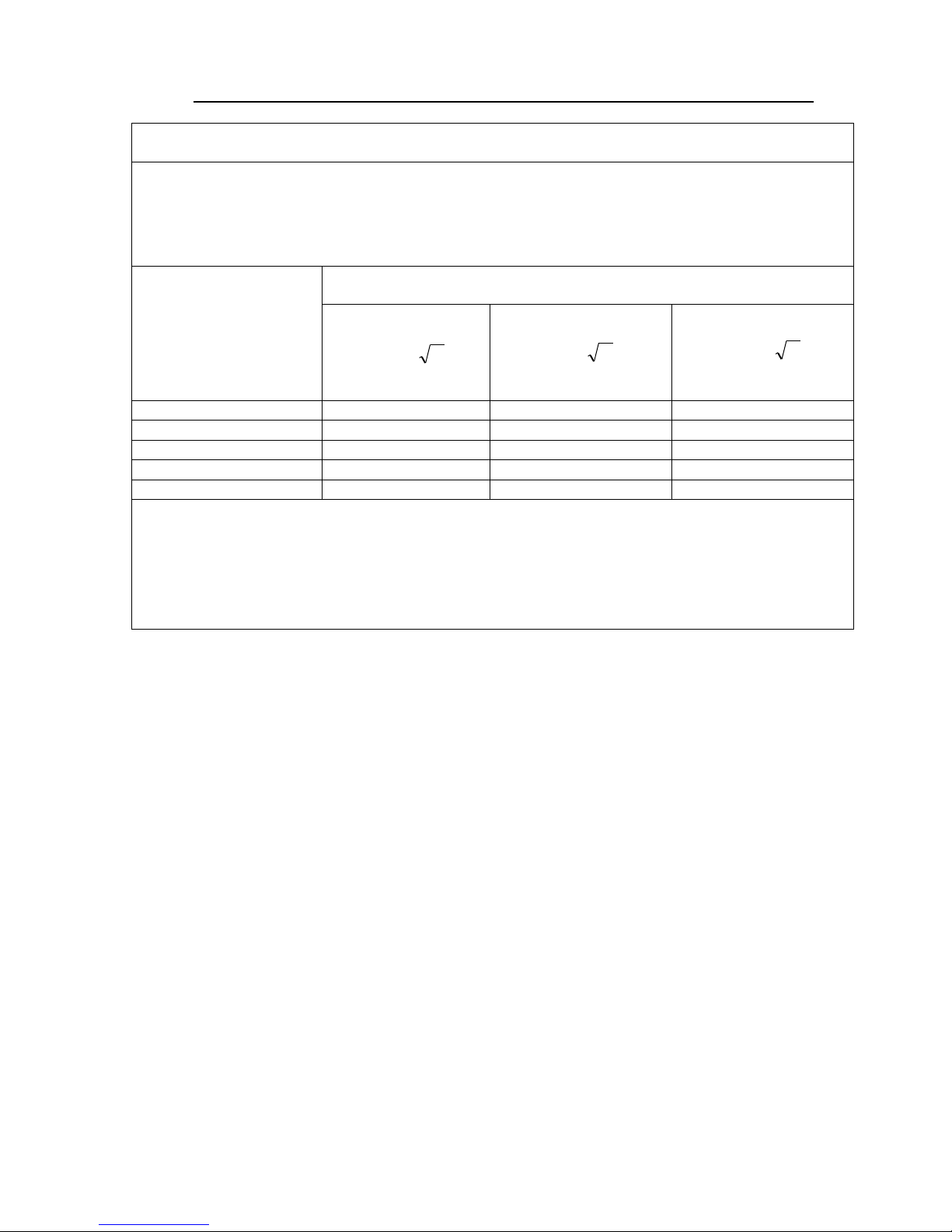
Echo/Vascular User Manual (15381-C) Page 42 of 46 DCR-00172
Pd 2,1=
Pd 2,1=
Pd 3,2=
Recommended separation distances between
portable and mobile RF communications equipment and the MPI Echo/Vascular Products
The product is intended for use in an electromagnetic environment in which radiated RF disturbances are
controlled. The customer or the user of the product can help prevent electromagnetic interference by
maintaining a minimum distance between portable and mobile RF communications equipment (transmitters)
and the product as recommended below, according to the maximum output power of the communications
equipment.
Rated maximum output
power of transmitter
Separation distance according to frequency of transmitter
(m)
150 kHz to 80 MHz
80 MHz to 800 MHz
800 MHz to 2.5 GHz
0.01
0,12
0,12
0,23
0.1
0,38
0,38
0,73
1
1,2
1,2
2,3
10
3,8
3,8
7,3
100
12
12
23
For transmitters rated at a maximum output power not listed above, the recommended separation distance d in meters (m) can be
estimated using the equation applicable to the frequency of the transmitter, where P is the maximum output power rating of the
transmitter in watts (W) according to the transmitter manufacturer.
NOTE 1 At 80 MHz and 800 MHz, the separation distance for the higher frequency range applies.
NOTE 2 These guidelines may not apply in all situations. Electromagnetic propagation is affected by absorption and reflecti on from
structures, objects and people.
Page 43

Specifications
Echo/Vascular User Manual (15381-C) Page 43 of 46 DCR-00172
Standard and Optional Configurations
EchoBed® X
VasScan Table™ X
ATTRIBUTE
STANDARD
OPTIONAL
STANDARD
OPTIONAL
Hand control
X - X - Side Rails
X - -
X
Single Pedal Brake/Mobility
X - -
X
Paper Roll Holder
X - -
X
Positioning Wedge
X - - X Sonographer Extension
- X -
X
1 Function Foot Control
- X -
X
3 Function Foot Control
- X - X IV Pole & Holder
- X -
X
Battery Functionality
- X - X 2nd Battery & Charger Kit
- X - X Under-bed Lights
- X - X Footboard
- - X
-
Page 44

Specifications
Echo/Vascular User Manual (15381-C) Page 44 of 46 DCR-00172
Replacement Parts and Upgrade Kits
The following items are replacements parts or upgrade kits for the EchoBed® X and
VasScan Table™ X. Some of the items below may not be suitable for all models of
product.
Part Description
Part #
Hand Control1
See Note Below
1 Function Foot Control
15543
3 Function Foot Control
15544
Multi-Function Control Kit
15505
Paper Roll Holder Kit
10098
Side Rail Kit
15433
IV Pole Kit
10855
Battery Functionality
15509
Replacement Battery
15395
Wall Charger Kit
15508
VasScan Footboard
14460
Carotid Headrest Kit
15507
Underbed Hook Kit
15510
Underbed Light Kit2
15511
Sonographer Extension Kit
15512
Sonographer Seat Replacement
15513
Pediatric/Geriatric Adapter
10097
Positioning Wedge
11943
Armboard Kit
11020
1. The hand control part number is specific to the product model. Please provide
the product model when ordering a new hand control.
2. The Multi-Function Control Kit is required with the Under-bed Light Kit.
Page 45

Echo/Vascular User Manual (15381-C) Page 45 of 46 DCR-00172
Warranty
Warranty
VasScan Table™ X
2
YEAR WARRANTY
This product is fully guaranteed against defects in material and/or workmanship during
the period indicated above, commencing with the manufacturing date. If a product fails
due to a manufacturing defect, Medical Positioning, Inc. (MPI) will repair or authorize
repairs to the product without charge, or replace the product at MPI’s option.
Preventative maintenance and repairs due to accident, improper care, negligence, or
other non-defect related failures are not covered by this warranty. This warranty does
not apply to products that have been modified without the advance written permission
of MPI.
MPI makes no other warranty, either expressed or implied, with respect to this product.
MPI specifically disclaims the implied warranties of merchantability and fitness for a
particular purpose.
The remedies provided herein are the customer’s sole and exclusive remedies. In no
event shall MPI be liable for any direct, indirect, special, incidental, or consequential
damages, whether based on contract, tort, or any other legal theory.
A 30 day return policy from the date of receipt applies to new products, subject to a
restocking fee and quality inspection. The product shall not be returned without prior
written authorization from MPI. The customer is responsible for all shipping charges and
any applicable duties or taxes.
Medical Positioning, Inc.
1146 Booth Street
Kansas City, Kansas 66103
(816) 474-1555
(800) 593-3246
Fax (816) 474-7755
WAR069-A
Page 46

Warranty
Echo/Vascular User Manual (15381-C) Page 46 of 46 DCR-00172
Warranty
EchoBed X
5
YEAR WARRANTY
This product is fully guaranteed against defects in material and/or workmanship during
the period indicated above, commencing with the manufacturing date. If a product fails
due to a manufacturing defect, Medical Positioning, Inc. (MPI) will repair or authorize
repairs to the product without charge, or replace the product at MPI’s option.
Preventative maintenance and repairs due to accident, improper care, negligence, or
other non-defect related failures are not covered by this warranty. This warranty does
not apply to products that have been modified without the advance written permission
of MPI.
MPI makes no other warranty, either expressed or implied, with respect to this product.
MPI specifically disclaims the implied warranties of merchantability and fitness for a
particular purpose.
The remedies provided herein are the customer’s sole and exclusive remedies. In no
event shall MPI be liable for any direct, indirect, special, incidental, or consequential
damages, whether based on contract, tort, or any other legal theory.
A 30 day return policy from the date of receipt applies to new products, subject to a
restocking fee and quality inspection. The product shall not be returned without prior
written authorization from MPI. The customer is responsible for all shipping charges and
any applicable duties or taxes.
Medical Positioning, Inc.
1146 Booth Street
Kansas City, Kansas 66103
(816) 474-1555
(800) 593-3246
Fax (816) 474-7755
WAR069-A
 Loading...