


USER'S MANUAL
PLEASE SEE BACK COVER FOR CONTACT
INFORMATION REGARDING REPAIRS AND
SALES
P/N 40150-66-MPH
(For Version 6.70 and above)
Disclaimer: The information contained here is accurate and reliable to the best of our knowledge at time of printing and is subject
to change without notice. No responsibility is assumed by MPH Industries for use of this information. MPH Industries, its logo,
Laser Atlanta, its logo and Advantage™, ProFiler™, SmartCharger, SpeedProof™, wiDAR™, SmartAdaptor™ & SpeedLaser®
are trademarks of MPH Industries, Inc. All other trademarks are the property of their respective companies. Patent Numbers
6,108,071; 7,286,955; 7,493,086 © 2012 MPH Industries, Inc. All rights reserved.
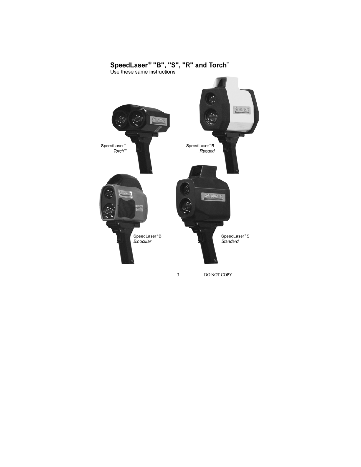

TABLE OF CONTENTS
1 INTRODUCTION...................................................................... 5
Cautions: .......................................................................... 6
Capabilities ...................................................................... 7
2 G
ETTING STARTED................................................................. 9
Packing List ..................................................................... 9
SpeedLaser
Battery Handle Power.................................................... 12
Connecting a Handle ..................................................... 13
To Power ON ................................................................. 14
To Power OFF ................................................................ 14
3 SPEED MEASUREMENT ........................................................ 15
4 U
Speed Detection ............................................................. 15
Approaching and Receding Targets .............................. 15
Approaching and Receding Targets .............................. 16
Manufacturer’s Recommended Daily Test..................... 17
SER SETTINGS ........................................................................... 21
Intensity and Contrast ................................................... 21
LCD Backlight ................................................................ 21
LCD Contrast ................................................................. 21
HUD Brightness ............................................................. 21
The MENU System ........................................................ 22
Main Menu .................................................................... 25
Test Mode ...................................................................... 26
Audio ............................................................................. 27
HUD Mode .................................................................... 28
AIMING MENU ............................................................ 29
Obstructed Mode ........................................................... 32
®
Controls & Layout .................................... 10
PPENDICES ................................................................................. 33
5 A
Do not copy
3
Appendices: Page #
A: Troubleshooting / Error Messages 33
B: Care and Maintenance 34
C: SpeedLaser
D: Measuring Surface Datum 37
E: LIDAR Menu Tree 39
Warranty 38
®
and Accessory Diagrams 36
Do not copy
4

CHAPTER 1 Introduction
Thank you for purchasing the SpeedLaser®. This rugged laser speed
detection device integrates the latest in solid-state laser technologies to
bring you hand-held, eye-safe laser speed and distance measurement.
The SpeedLaser
used to calculate range and speed of targets at a distance. Depending on
reflective characteristics of the targets, the environment and other
®
is a Class 1 eye safe, multi-function device generally
factors, distance may vary.
The technology utilized by the SpeedLaser
Detection And Ranging. Your SpeedLaser
pulse of laser light to travel from the LIDAR to the target vehicle and
back (pulsed time-of-flight). This round trip time is converted to a
distance (d=ct/2). The distance to the target vehicle is calculated in this
manner over two hundred times per second. Sophisticated computer
algorithms combine these individual range calculations to compute the
extremely accurate speed displayed. The IACP lists this device on their
product list (CPL) after testing to their specifications.
To get the most from your new SpeedLaser
through this manual. For your convenience and ease of understanding,
it has been divided into 5 sections:
Chapter 1: Introduction
Chapter 2: Getting Started
Chapter 3: Speed Measurement
Chapter 4: User Setting’s
Appendices: Information on care, troubleshooting, and
specifications
If you have questions or comments, please do not hesitate to contact us.
PLEASE SEE BACK COVER FOR CONTACT
INFORMATION REGARDING REPAIRS AND SALES
®
is called LIDAR: LIght
®
measures the time it takes a
®
, please take the time to read
Do not copy
5

Cautions:
Every step has been taken to ensure your SpeedLaser® is completely safe to use.
However, certain common-sense precautions should always be taken when using
your SpeedLaser
®
.
• Do not open the LIDAR unit’s housing under any circumstances.
• Do not point the SpeedLaser
• Use only MPH Industries approved power sources and accessories.
(use of unauthorized accessories may void the warranty)
• Do not store SpeedLaser
• Do not place SpeedLaser
• Always transport the SpeedLaser
SpeedLaser
a Pulse Width of 100 nsec nor a laser power of 238 uWatts, and has a Class 1
®
is a Class 1 Laser Product which does not exceed a PRF of 240Hz,
Laser Product label in the serial number window (see index D on the Layout
Figures found on pages 11 & 12).
®
directly at the sun.
®
in areas of high humidity.
®
on unstable surfaces.
®
in its carrying case.
Caution: The use of controls or adjustments or performance of procedures
other than those specified herein may result in hazardous radiation
exposure.
Any certifications included are void if the product is opened, altered, installed in
other equipment or used for purposes other then intended by the manufacturer.
Using any charger other than those supplied by MPH Industries will also void
the certification.
Although optical viewing instruments may increase eye hazard, it is unlikely
that actual damage can occur. Prescription eyeglasses, contact lenses, and
sunglasses are not considered optical gain devices since they merely correct the
focus of the human eye to normal.
Optical devices that provide magnification may increase the risk of eye-hazard.
These include binoculars, telescopes and magnifying glasses.
Certain municipalities and countries require settings to differing measurements
(mph or km/h). Your unit is factory set to the appropriate unit of measurement.
The pictures/drawings/illustrations in this manual are for illustration only and
are shown in miles per hour and feet as well as kilometers per hour and meters.
Do not copy
6

Capabilities
Performance
• Target Acquisition in 0.3 seconds
• Speed Accuracy of one unit of measure
Advanced Input-Output
• Remote Fire trigger switch
• Full Remote control via RS-232 port
• Data Collection via RS-232 port
Ease of Use
• Menu Driven
• Head Up Display (HUD) shows both target and speed or distance
• Optional Rechargeable NiMH or 9 volt Battery Handle
• Optional 12 Volt Cigarette Adapter
• Optional 8X Monocular (S & R only)
• Optional Monopole (S & R only) and Tripod for mounting
• Optional Mapping system upgrade (S & R only)
• Optional USB/SD Memory Drive
Environmental Features
• Water Resistant (R = IP67, optional for B & S which are IP56)
• Ruggedized Housing
• Rechargeable NiMH Battery Handles (S & R only, B batteries
are NiMH internal)
(Dependent on environment and reflective characteristics of target)
data through the same sighting mechanism
Do not copy
7
Optional accessories, carrying
cases and cords in a variety of
styles are available.
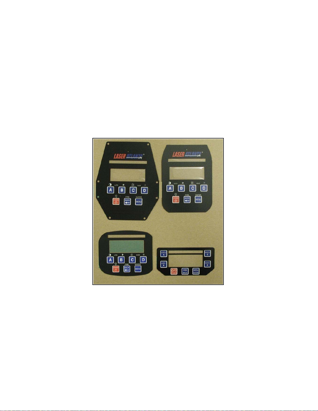
All four models of the SpeedLaser® use the same display and
user interface. The four different keypads are shown below. Any
feature or function shown on one display or key board is available
on all models. The menu tree described through out this manual
is used with all of the key pads:
Do not copy
8

Chapter 2
Getting Started
PACKING LIST
Please check to make sure the following items that were ordered are
included in your shipment, such as:
• SpeedLaser
• Battery Handle (S, T & R only; optional on B)
• Carrying Case
• Battery Charger (if applicable)
• 12 volt Charging Cable (if applicable)
• User's Manual
®
LIDAR Unit
Additionally, you may have received the following optional parts:
• RS-232 Serial Data Cable
• 8X Monocular
• Additional Battery Handles
• Additional optional charging cords and accessories
(Please see Appendix C for diagrams of some of these items.)
Do not copy
9
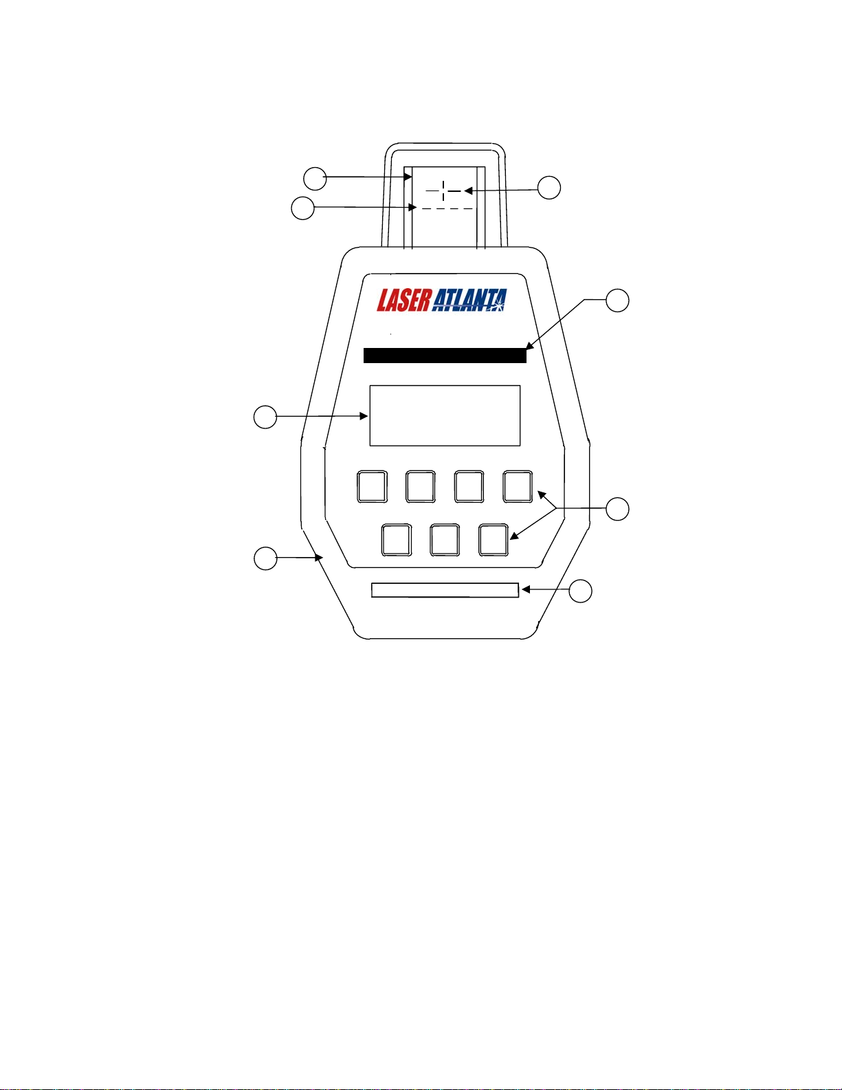
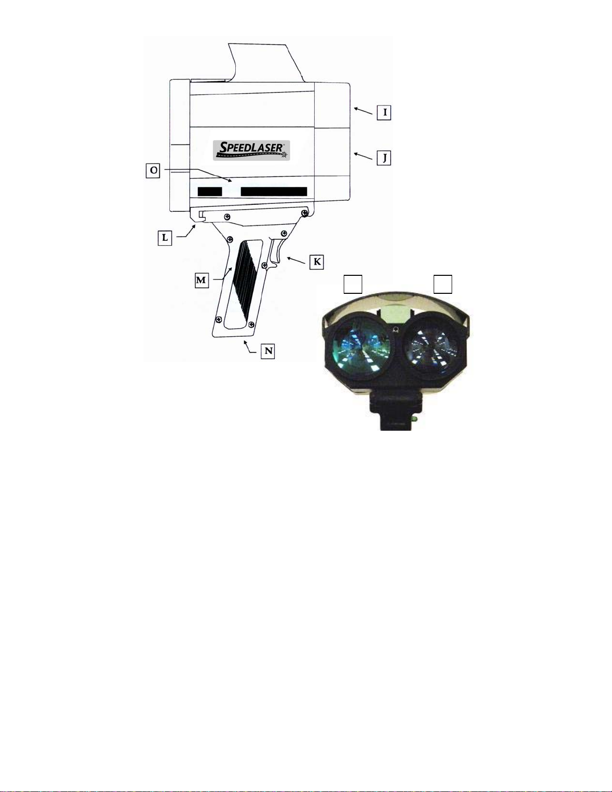
SpeedLaser® Controls & Layout
A
t
(Typical – wording may vary in different versions.
Drawings are for illustration only.)
A
C
E
G
A: Head Up Display (HUD) E: Liquid Crystal Display (LCD)
B: HUD Sighting Reticle F: Keypad Keys
C: HUD Character Display G: Rear Bumper (R model only)
D: Serial #, Laser Warning H: Optional Memory Drive Slot
Do not copy
LASER ATLANTA LLC S/N: 23456
NORCROSS, GA 30071 Class 1 Laser Produc
LCD
B C D
POWER
10
FIRE
BACK
HUD
ENTER
MENU
B
H
D
F
I J
I: Transmit Optics M: Battery Handle (most models)
J: Receive Optics N: External Data/Charging Port
K: Handle Trigger (Tripod mountable handle
L: Handle Latch has data port on the side)
O: Laser Warnings (Alternate
Location Select Models Only)
Do not copy
11
Battery Handle Power
The SpeedLaser® may come equipped with a rechargeable battery handle
shipped uncharged
completely (10-12 hours) with the wall charger or 12 Volt cigarette cable
before first use. Each handle provides an average of 8 hours or more of
continuous use per charge (hours vary based on use and conditions).
These handles, and the B model with internal batteries, are also capable
of powering the SpeedLaser from a 12V source such as an automotive
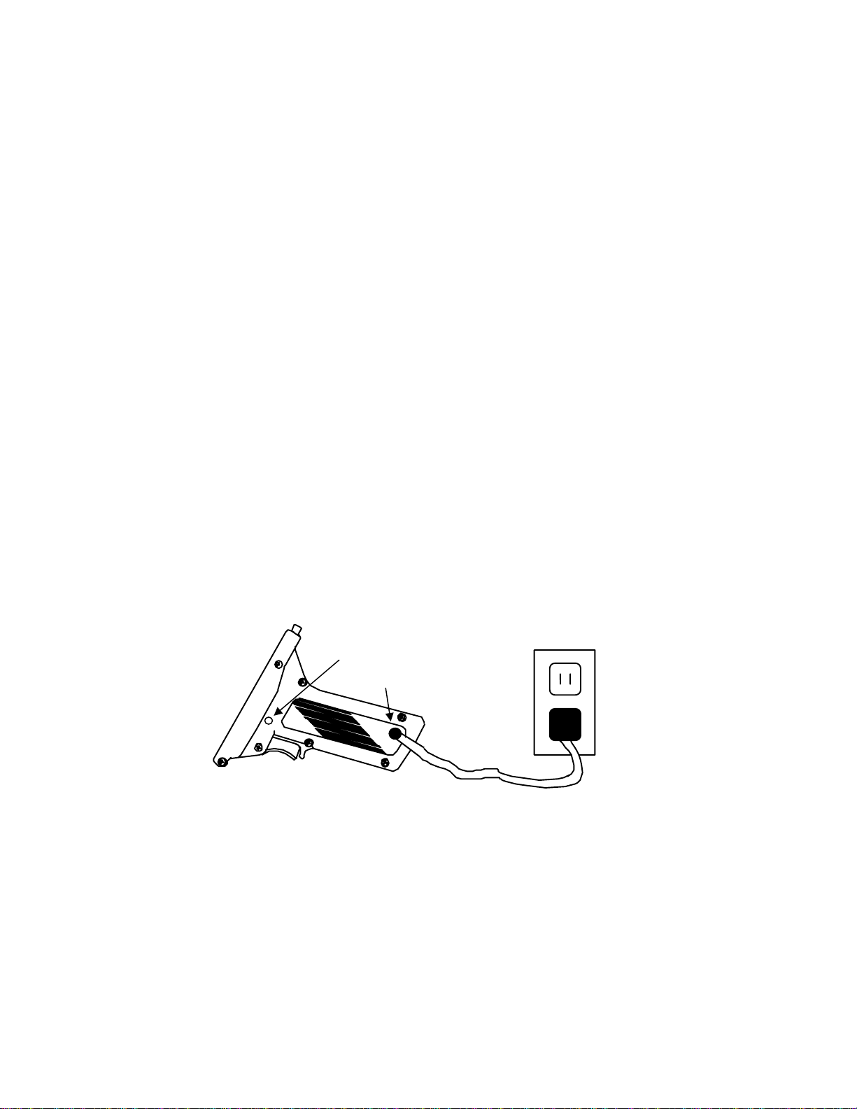
cigarette power adapter using the cable if provided. Plug the small
circular connector onto the Charging Connector on the side of the handle
and the cigarette adapter end into an automotive cigarette-power adapter.
You can charge the handles in this manner while operating the unit. A
Power Handle connected to a B will charge the internal batteries. While
the 9v handle can be used with the B it is not efficient.
To charge your battery:
1. Plug the circular connector into the Charging Connector on the
side of the handle or bottom of B. Do not force the connector as
it is keyed...slowly rotate the connector (holding the black
rubber) and push gently until it clicks and locks into place.
2. Plug the charger into a standard 120 VAC power receptacle OR
plug the cigarette adapter into a power source.
3. Charge the batteries for ten to twelve hours.
4. To remove the connector, pull gently away from the handle on
the outside of the metal connector.
5. Unplug the charger from the wall. The batteries are ch arged.
CAUTION! DO NOT:
• Charge batteries with chargers not supplied by MPH Industries.
• Short circuit the battery pins
• Charge batteries for over sixteen (16) hours continuously
(B batteries are internal). You may need to charge it
Green Charging Light
Charging Connector
Do not copy
12

Connecting a Handle
(All Models and B models equipped with handle mount)
To install a handle onto the SpeedLaser
1. Press the Handle Latch forward on the handle.
2. Push the front of the handle into the front Handle Catch on the
bottom of the SpeedLaser
3. Rotate the rear of the handle upward.
4. Release the handle latch.
®
.
®
:
NOTE: Make certain the handle latch slides into position and secures the
handle to the SpeedLaser
back to secure the handle to the SpeedLaser
®
. If necessary, push the handle latch toward the
®
.
Do not copy
13

Turning the SpeedLaser® ON and OFF
TO POWER ON
1)
Press and hold the PWR key located on the back of the
SpeedLaser
®
for approximately one second.
NOTE: The hardware and software Built In Test (BIT) automatically
runs when the unit is first powered ON. When BIT is completed
successfully the LCD will display “SYSTEM READY.” or
“Self-Test Passed”. Either indicates that the BIT has been completed
successfully.
TO POWER OFF
1) Press and HOLD the PWR key on the back of the
SpeedLaser
NOTE: Keep the key pressed until “POWERING DOWN” is displayed
on the LCD then release the keypad. If the button is not depressed for a
long enough time, it toggles the LCD backlight ON and OFF.
®
(see note) for approximately three seconds.
Do not copy
Laser Atlanta
SpeedLaser
P/N YYYYY-EEEE vx.xx
SYSTEM READY.
LCD HUD
A B
FIRE
PWR
C
D
MENU BACK
Power Key
14

Chapter 3
p
Speed Measurement
When the SpeedLaser® is first turned ON, it automatically and quickly runs the
Built In Test (BIT) functions. To capture a speed, simply follow the procedure
below when the BIT is complete.
SPEED DETECTION
NOTE: Always verify operational procedures for Alignment Check.
1. Align the HUD Sighting Reticule (+ symbol in the HUD) on the target
you wish to measure the speed of.
2. Squeeze and hold the Handle Trigger (on B press the fire button on top)
until the speed is displayed.
3. Release the Handle Trigger (or fire button) to stop measurement,
momentarily display the information in the HUD and lock information
on the LCD. The LCD displays the information until one of the
following occurs:
a.) The laser is fired.
b.) The unit is powered down (by the operator or typically after
c.) The menu button is pressed.
The speed will be shown in three places…twice on the rear right of the LCD and
also momentarily in the HUD (when selected) character display. Notice that two
of the speed displays are truncated to the nearest mph or km/h.
The distance to the target will be shown on the left side of the LCD.
about 10 minutes of inactivity) or
HUD
S
eed
- 13
NOTE: Pressing the trigger/fire button will take you to the Speed Display Page
regardless of any other mode the SpeedLaser
when in the TEST mode.)
®
may be in. (The exception is
LCD
Range
Display
LCD
Do not copy
15
Speed
Display

APPROACHING AND RECEDING TARGETS
g
g
The SpeedLaser
(oncoming) and receding targets.
®
can measure the speeds of both approaching
When the target is receding, a “-” sign will precede the speed displayed
in the HUD and on the LCD.
Example of an Approaching target
34
Oncomin
Target
Oncoming
Target
(No “-“ sign)
Do not copy
Example of a Receding target
Recedin
Target
- 13
Receding
Target
(“-“ sign)
16

Manufacturer’s Recommended Daily Test
In keeping with NHTSA (National Highway Traffic Safety
Administration) and IADLEST (The International Association of
Directors of Law Enforcement Standards and Training) guidelines
general operational considerations for LIDAR Speed Measurement
devices, the operator must perform the following accuracy checks prior
to beginning enforcement operations:
1) Internal Circuit Check
2) LED Segment Test
3) Range (Chronometer) Accuracy Test
4) Horizontal Sight Alignment Test
5) Vertical Sight Alignment Test
WHAT THE DAILY TEST ACCOMPLISHES:
To ensure that the SpeedLaser
®
SpeedLaser
should be tested using the Manufacture’s daily test
®
is in good working order, the
described later in this chapter. This test restores the factory default
settings, checks the LIDAR hardware (including the program and
dynamic memories), tests the displays and timing circuits, and then
allows the operator to verify that the HUD aiming crosshairs are
correctly aligned with the laser beam.
NOTE: The alignment crosshairs in the HUD are set at the factory and
generally do not need realignment over the life of the SpeedLaser
1) Internal Circuit Check
When the operator presses Menu, followed by Test, (button A on the
keypad), the SpeedLaser
BIT program tests the hardware and software by verifying that the
SpeedLaser
®
firmware is loaded correctly and then checking that the
®
runs a BIT (Built-In-Test) program. The
®
.
processor is executing the data gathering, storing (memory), sorting,
filtering, conversion and linear regression algorithms correctly.
2) HUD’s LED Segment Test
This test allows the operator to verify that the seven-segment display,
used to show speed of the target vehicle, is in good working order by
displaying a simple known pattern. The operator can then confirm that
each segment operates correctly and verify the presence of the aiming
reticle.
3) Range (Chronometer) Accuracy Test
Do not copy
17

The SpeedLaser® hardware ONLY measures Time. Range and
Speed are computed values derived from multiple time
measurements by the firmware, which was checked for proper
operation during BIT. The design and accuracy of the firmware was
verified as part of the IACP certification and subsequent testing
processes.
This test uses the SpeedLaser
®
’s high-speed chronometer (timer) to
measure the time it takes a light pulse to travel a known distance
®
(i.e.; from the SpeedLaser
Since the speed of light in air is known, the SpeedLaser
to a target at a known distance and back).
®
can
calculate the range that the light pulse traveled. The operator then
compares the reported range to the known distance to the target. To
verify that the timing hardware is working correctly the computed
range must match the known distance to within ± 1 foot (30 cm). At
least two such comparisons using targets at least twenty (20) feet (6
meters) apart must be made.
In normal operation, the SpeedLaser
light pulse to travel from the SpeedLaser
back. The SpeedLaser
®
makes hundreds of such round trip time
measurements each second, each time measurement is converted to a
range and stored. When the SpeedLaser
®
measures the time it takes for a
®
to a moving vehicle and
®
has sufficient stored
ranges, it performs a linear regression calculation that yields the
speed of the vehicle. Numerous firmware filters are used to confirm
the computed speed before it is displayed.
4) Horizontal Sight Alignment Test
This is a test to confirm that the sighting system and the invisible
®
light pulse emitted by the SpeedLaser
operator uses the sighting system to aim at an object and then
confirms that the light pulses of the SpeedLaser
object by observing that the SpeedLaser
are aligned horizontally. The
®
®
is reporting the range to
are hitting that
that object. The operator then moves the sighting system off of the
object and observes that the reported range changes, just as the
sighting system is no longer on the object and indeed should change.
5) Vertical Sight Alignment Test
Same as Horizontal alignment test but in the vertical axis
Do not copy
18

When the SpeedLaser is initially powered ON, it automatically and very quickly
runs a hardware and software Built In Test (BIT). When successfully
completed, the LCD screen will display “SYSTEM READY” or “Self Test
Passed”. You are now ready to complete the following recommended daily
tests, listed as #1 through #5, prior to conducting any enforcement activity.
Running the Manufacturer’s Recommended Daily Tests
1) Internal Circuit Check
Press MENU followed by “A” on the keypad, which selects Test.
The LIDAR will then automatically:
a) Enter the RESET & TEST Mode
b) Restore factory default settings
c) Run the hardware Built In Test (BIT)
d) Run the software BIT in cluding dynamic memory test
e) Runs an LED count test (1111, 2222, …, 9999)
f) Defaults the HUD display to .8.8.8.8
Wait for “TEST PASS” or “Memory-OK” to be displayed. Either
indicates that steps a to d have been completed successfully.
2) Light Segment Test
Confirm e or f, the HUD is displaying aiming “+” with the data “.8.8.8.8”.
3) Range (Chronometer) Accuracy Test
Confirm that the LIDAR can correctly compute two or more known ranges
using any one of the following methods:
a) From one location, range to two targets at known distances.
b) From two locations, range to one target at a known distance.
c) Range to a random target, back up a known ‘delta’ distance, and
confirm that LIDAR computes a new range with the same delta
distance. Then back up a second, but different delta dist ance and
confirm that LIDAR computes a new range that matches the new
delta range.
d) Combine method a) with the horizontal and vertical alignment tests
(4 and 5) on next page. This requires that the targets used for the
Horizontal and Vertical alignment are at different known ranges.
Using your preferred method from above:
a) Stand at the selected position.
b) Aim at selected target.
c) Squeeze and hold trigger/fire button until tone sounds (range is
computed).
d) Confirm that reported range is within ± 1 foot (30 cm) of expected.
e) Repeat steps a) thru d) using a known distance that is at least
20 feet (6 meters) different than the first known distance.
Do not copy
19

4) Horizontal Sight Alignment Test
a) Locate a vertical object (such as a utility pole) with open sky
behind, preferably at a distance greater then 150 feet/45 meters.
b) Aim to the left or right of the object, pull and hold the trigger/fire
button.
c) While keeping the trigger/fire button pulled, slowly sweep the
crosshair sight across the vertical object.
d) The distance to the pole should be displayed once the target edge
is inside the HUD crosshair.
e) Press D (Done/Next) to display next step.
5) Vertical Sight Alignment Test
a) Turn the unit 90 degrees sideways and repeat steps 4) a – e.
b) Press MENU or DONE to exit Test Mode.
Note: If desirable, the horizontal and vertical alignment tests may be
conducted using an horizontal object, such as a utility wire, with
open sky. However, it will be necessary to turn the Lidar unit 90
degrees to conduct the horizontal test and return it to the upright
position when testing the vertical axis or plane.
Do not copy
Sweep from
the LEFT
Sweep from
the RIGHT
20

Chapter 4
User Settings
INTENSITY AND CONTRAST
The intensity/contrast of the SpeedLaser® are set outside of the Menu
system. Above each letter is a symbol that shows what the key function
is outside of the menu. Before entering the menu you can activate the
backlight, set the LCD contrast or set the HUD intensity.
While factory reset (Menu > Test) will automatically turn off the
backlight, the LCD contrast and HUD intensity are only set by the user
therefore do not change during the test. This allows an appropriate
intensity/contrast level to be established before running the daily test.
LCD Backlight
Briefly pressing the PWR button will toggle the backlight ON and
OFF.
LCD Contrast
Use the A and B keys to adjust the LCD Contrast:
• The A key adjusts the LCD Contrast DARKER.
• The B key adjusts the LCD Contrast LIGHTER.
HUD Brightness
Use the C and D keys to adjust the HUD Contrast:
• The C key adjusts the HUD intensity HIGHER.
• The D key adjusts the HUD intensity LOWER.
Do not copy
21

/
THE MENU SYSTEM
The SpeedLaser® provides a number of user settable features to help the
user in making range and speed measurements. These are accessible
through sub-menus. The menu system is reached by pressing the MENU
key located on the back of the SpeedLaser
• The top left of the LCD displays the Menu Name.
• The top right of the LCD displays the Menu page letter. This
®
.
reflects the letter sequence of keys that have been pressed since
the first menu page (Pg 0).
• Other lines list choices selectable by the A, B, C, and D keys.
The menu system is navigated via the following keys:
(Combined menu used for example only)
A: Used to select choice A
B: Used to selec t choice B
C: Used to select choice C
D: Used to select choice D
PWR: Release quickly to toggle backlight on and off
PWR: Hold for about three seconds to turn off the SpeedLaser
BACK: Used to go back to the previous menu page
MENU: Used to enter/exit the Menu
®
Menu
Name
SubMenu
Do not copy
Menu
Page No.
LIDAR MENU Pg 0
A>Test Hud<C
B>Audio Obstructed:D
LCD HUD
FIRE
22
C
D
A B
PWR MENU BACK
Function
@=On
:=Off
Press this key to
enter/exit the
menu system.

For each menu choice, on the outside left or right edge of the LCD is the
letter matching the key to be pressed to activate the option. Between
each key letter and its corresponding description is a symbol. The
meanings of the symbols are as follows:
> Or < (Greater/less than)
When the “>” symbol appears next to a letter key, pressing that letter key
will select the indicated sub-menu.
: (Colon)
When the “:” symbol appears next to a letter key, the named function is
currently set to OFF. Pressing this letter key will turn ON the named
function. If the function is of a “choose one” nature, then the related
functions will automatically be turned OFF.
@ (At)
When the “@” symbol appears next to a letter key, the named function is
currently set to ON. If the function is of an “on/off” type, then pressing
this letter key will turn OFF the named function. If the function is of a
“choose one” nature, then you must select one of the other functions to
turn this function OFF.
) Or ( (Parentheses)
When the closed “)” or open ‘(‘ parenthesis symbol appears next to a
menu selection, two presses of the corresponding key are required to
enter the associated menu (represented in the menu tree, “LIDAR Menu
Tree” Appendix with a double arrow). The first key press activates the
selection using the default options as is shown on the LCD by the
changing of the symbol to an ampersand (“&”).
A lower-case key letter designates a menu choice that is not currently
selectable (usually because the necessary hardware is not present or
because it is dependent upon another option).
Please refer to LIDAR Menu Tree Appendix.
Do not copy
23

Notes
Please note that the current settings are automatically saved when you
turn the unit off and will not be lost even if the battery handle is
removed after the unit is powered off.
When the daily Test is run, the SpeedLaser
®
automatically restores all
common user settings to their factory default values. Certain user
selectable preferences such as “Jammer Detect”, “LCD contrast” and
“HUD intensity” are retained.
The remainder of this Chapter presents a diagram and description of each
sub-menu.
To quickly access any desired menu, press the MENU key and then the
sequence of letter shown at the top right of the display diagram on any
page.
For example, to select the Audio Quality Chirp, you would press the
following keys in sequence:
MENU | Audio | Quality Chirp or MENU | B | C
Do not copy
24

Main
Menu
The Main Menu is the starting menu page for all user configurable
functions. These functions are divided into four groups:
• Test
• Audio
• HUD
• Options
See the Menu Tree and the description pages that follow for instructions
on using these settings.
Reminder: The user settings are remembered until the Test menu is run.
The laser will revert to standard factory settings when the Test menu is
selected.
NOTE: The hardware and software Built In Test functions are
performed automatically upon powering the SpeedLaser.
LIDAR MENU Pg 0
A>Test HUD<C
B>Audio Options<D
LCD
A B
FIRE
PWR
# Action Key
1 Turn On PWR
2 Select MENU MENU
C
HUD
D
MENU BACK
Inside the Options group, the “Obstructed” feature is built into
every SpeedLaser while the FtC™ or Following to Close™ and
Camera features are purchased options. The selector letter will
be upper case if the option is installed.
Do not copy
25

Test Mode
Performing the Daily Test (older versions use “Memory-OK” instead of “TEST
PASS”. Both messages are functionally identical.)
MENU A
RESET & TEST
P/N YYYYY-EEEE
TEST PASS
Units:ft,mph
A B
PWR
# Action Key
1 Turn On PWR
2 Select MENU MENU
Pg A
PWR:E---*F
NEXT<D
LCD HUD
C
FIRE
MENU BACK
vx.xx
D
RESET & TEST
P/N YYYYY-EEEE
TEST PASS
or
Units:m,kmh
A B
PWR
LCD HUD
3 Select TEST MODE A
The Daily-Test performs the following functions:
• The SpeedLaser
• The software Part Number & Version are displayed in LCD.
• The program and storage memories are tested.
• The battery voltage is displayed on an Empty - - - - Full scale.
• The speed and distance units of measure are displayed on the
®
setting are restored to factory default values.
LCD. (Note: These units are pre-configured at the factory and
cannot be set by the end-user.)
• All LED segments in the HUD are cycled through the numerals
1 to 9 and then finally displayed as .8.8.8.8
• Range (distance measurement) mode is automatically turned on.
This allows the operator to perform the range (chronometer) and
alignment checks (see procedure starting on page 20.)
If any of the diagnostic functions fail, a failure warning will be displayed
on both the LCD and in the HUD. A warning tone will sound and the
SpeedLaser
®
will prohibit firing of the laser. The operator should
attempt to power the unit down and back on and run the daily-test again.
Pg A
PWR:E---*F
C
FIRE
vx.xx
NEXT<D
D
MENU BACK
Do not copy
26

Audio
Toggling the beeper tone ON and OFF
FIRE
C
D
MENU BACK
MENU B (your unit shows one of these configurations)
AUDIO MENU Pg B
A:Off
B:Valid Result
C:Quality Chirp
AUDIO MENU Pg B
A: Valid Result
B: Quality Chirp
LCD HUD
A B
C
D
LCD HUD
A B
PWR
# Action Key
1 Turn On PWR
2 Select MENU MENU
3 Select AUDIO B
4 Select preference Off | Valid | Quality A | B | C
“OFF” is not present on certain municipalities’ versions
FIRE
MENU BACK
PWR
If selection Off is NOT selected, the unit will emit a short beep each time
a menu key is pressed.
If selection Valid Result or Quality Chirp are selected, the audio beeper
will sound for the following conditions:
Valid Result The beeper will emit a tone when a valid speed or
distance measurement is made.
Quality Chirp When the SpeedLaser
®
is computing range and
speed calculations (in Range Average or Real-time
Range modes only), a tone representative of the
quality of the received laser signal is sounded.
When strong laser returns are acquired, the tone will
be solid. Weaker returns will give a weaker, broken
tone.
NOTE: The following conditions will signal an alarm regardless of the
settings on this menu page.
Voltage Low A solid tone will sound when the voltage is low.
Fail Any failure mode will sound a solid tone.
Do not copy
27

HUD Mode
Sets what information is displayed on the HUD
(older versions do not have a choice of aiming as indicated
by “d” in their display. Auto Rotate not available in all units.)
Auto Rotation
MENU C
HUD MENU Pg C
A@Speed Mapping<C
B:Range Aiming:D
LCD HUD
A B
C
D
PWR
FIRE
MENU BACK
# Action Key
1 Turn On PWR
2 Select MENU MENU
3 Select HUD MENU C
4 Select preference A | B | C | D
This setting chooses what is displayed in the HUD; Speed, Range,
both Speed and Range, or Accident Mapping data and selects the
Aiming Reticle Menu
Speed Select A to display Speeds in the HUD.
Range Select B to display distances in the HUD.
Both Speed and Range
Select both A and B to alternately display Speed and
Distance in the HUD. The values will rotate between
the current speed and the current range.
Do not copy
28

Mapping Select C to use the SpeedLaser® with the optional
mapping accessories to map an Accident Scene. This
sets the SpeedLaser® to compute ranges using the
stationary range only algorithm found in the
Advantage™ Mapping/GIS product.
Aiming Pressing D selects the HUD Menu uses to control the
appearance of the aiming reticle.
crosshair mode is available on older units).
(Lower case(d) indicates only
AIMING MENU
Setting the appearance of the HUD aiming reticle
MENU CD
AIMING MENU Pg CD
A:Crosshair Dot:C
B:Original Default@D
LCD HUD
A B
C
D
PWR
FIRE
MENU BACK
# Action Key
1 Turn On PWR
2 Select MENU MENU
3 Select HUD MENU C
4 Select AIMING MENU D
5 Select preference A | B | C | D
This setting chooses the appearance of the HUD aiming reticle. The four
choices are shown on the next page
Crosshair Select A to display a reticle with a gap aspect ratio similar to
the end view of a vehicle. The width of the laser beam
matches the width of the gap in the center of the reticle.
Original Select B to display a reticle with a square gap. The width of
the laser beam matches the width of the gap in the center of
the reticle.
Dot Select C to display a small dot in the center that will be
located in the center of laser beam. The laser beam is larger
than the dot.
Do not copy
29

Default Select D to display the small dot in the center that will be
located in the center of laser beam and to display the original
square gap reticle. The width of the laser beam matches the
width of the gap in the center of the reticle.
Do not copy
30

Crosshair
Original
Dot
AIMING MENU continued (diagrams below are
indicative of the configurations)
Default
Do not copy
31

Obstructed Mode
Turning the Obstructed mode On / Off
MENU D
OPTIONS MENU Pg D
A@Obstructed = OFF
b:FtC (tm) = OFF
c:Camera = OFF
Upper case b: or c: indicates
feature is available, instructions
found in document: listed below:
FtC ™ see: 40378
Camera see: 40379
LCD HUD
A B
C
D
PWR
FIRE
MENU BACK
# Action Key
1 Turn On PWR
2 Select MENU MENU
3 Obstructed (Toggles On / Off) D
Set to ON when firing the LIDAR through the patrol vehicle window, or
when RAIN, SNOW, FOG or other OBSTRUCTIONS are present.
Normally LIDARs attempt to compute the speed of the first object that
each laser pulse strikes. When standing in the open on a clear day this
works well. But when a LIDAR is used from inside a vehicle or when
weather is inclement or when objects like bushes and signposts partially
block the view of the target vehicle, this approach does not work as well.
The SpeedLaser
mode that allows the SpeedLaser
®
Obstructed On/Off setting is an advanced filtering
®
to process multiple ranges for each
laser pulse. The LIDAR sees both the target vehicle and the obstructing
object (rain, patrol vehicle window, snow, chain link fence, etc) and can
filter out the random items like snow and the obstructing items like the
window, allowing speed to be computed for the selected target vehicle.
This method does not require limiting the minimum range or having the
operator set up some target window. In fact, Obstructed works from the
standard minimum range of 5 feet (2 meters) out to over 2700 feet (900
meters).
Do not copy
32

APPENDIX A
TROUBLESHOOTING PROCEDURES
If you suspect your SpeedLaser® is malfunctioning, please check the
following items:
Troubleshooting:
Symptom: Possible Cause:
SpeedLaser® will not power on Battery Handle not charged sufficiently; 12V DC
All Black Dots appear on the
LCD screen
Cannot see anything on the LCD
screen - Blank
Cannot see HUD displays crosshairs, DOT, or Both
Continuous beeping noise
coming from unit after it is
powered on
Battery handle not fully charging. Battery handle may be worn & needs to be replaced
SpeedLaser® will not range to
distant targets
Error Messages:
Error Message Message Meaning Operator Action
EEPROM Data Not
Found
HELP Voltage too low Recharge the Battery
Low Battery Voltage too low Recharge the Battery
coiled power cord not plugged in; Brass contacts on
bottom of the unit need to be cleaned. Take a pencil
eraser & clean contacts from corrosion.
LCD contrast needs to be adjusted. See Chapter 4 on
'How to adjust the LCD contrast'.
LCD contrast needs to be adjusted. See Chapter 4 on
'How to adjust the LCD contrast'.
SpeedLaser® setup
HUD brightness set to low or to high. See Chapter 4
on 'How to adjust the HUD contrast'.
Make sure that the battery handle is fully charged;
clean the brass contacts on the bottom of the unit.
Take a pencil eraser & clean the contacts from
corrosion.
or refurbished.
Target is not reflective enough; Target is too far
away; Lens blocked or fogged.
Cycle Power
defaults not located
If you are unable to resolve the problem on your own, please contact us
at: techsupport@laseratlanta.com
If you need to return your unit for service, please contact us at:
www.laseratlanta.com or repair@laseratlanta.com to request a Return
Materials Authorization (RMA) number.
Do not copy
33

APPENDIX B
CARE AND MAINTENANCE
NO USER SERVICEABLE PARTS INSIDE
General Care Considerations:
DO:
• Transport the SpeedLaser
• Occasionally clean the SpeedLaser
DO NOT:
below)
• Point the SpeedLaser
• Place on unstable surfaces
• Open the SpeedLaser
CLEANING THE SPEEDLASER®’S OPTICS
WARNING! The SpeedLaser
Surfaces to Clean:
Materials:
1. Lint-free cloth or optical cleaning tissue
2. Soft bristled brush
3. Isopropyl Alcohol
Method:
1. Brush loose debris from optical surfaces with brush or cloth.
2. Moisten cloth with isopropyl alcohol.
3. Gently wipe optical surface in a circular motion. Change
Care must be taken when cleaning these surfaces.
Scratching the lenses may lead to reduced range.
The LASER TRANSMITTER OPTICS, RECEIVER OPTICS,
HUD COMBINER GLASS, and HUD SEALING WINDOW
may be cleaned as needed.
tissue if any debris is visible.
®
in its carrying case
®
at the sun
®
®
Optics (see procedure
®
’s optical surfaces are coated glass.
Do not copy
34

Q
O
P
R
RECEIVER OPTICS
P.
HUD COMBINER GLASS
O.
R.
Q.
TRANSMITTER OPTICS
Do not copy
35

APPENDIX C
SpeedLaser® & ACCESSORIES
Do not copy
36

Appendix D
MEASURING SURFACE DATUM
The measuring surface datum is located 4 inches/10cm back from the
face of the glass front of the unit. (This location corresponds to the
vertical center of gravity of the unit.)
Do not copy
37

Limited Warranty
MPH Industries warrants all SpeedLaser
materials and workmanship under normal use and service for which such products are
intended (specifically excluding defects or damage caused by misuse, negligence,
droppage or accident) for a period of ninety (90) days from date of purchase. This warranty
specifically excludes accessories, batteries and software. Accessories’ warranty period is
thirty (30) days from date of purchase. Some of the components of these products are
custom made electronic components and some products resold from other MPH Industries
sources and MPH Industries relies on the sources of these components for replacement
products and parts. Therefore, MPH Industries’ commitment is for its best commercially
reasonable efforts to provide for this warranty.
During this warranty period MPH Industries will make best commercially reasonable efforts
to replace defective materials and correct faulty workmanship at no charge, provided the
product is returned to MPH Industries within the warranty period. If MPH Industries is
unable to replace defective materials or correct faulty workmanship, MPH Industries will
replace the product at no charge if product replacement is available within a commercially
reasonable timeframe. These are your sole remedies for any breach of warranty. MPH
Industries shall not be liable for any loss or damage resulting, directly or indirectly, from the
use or loss of use of such product, including loss of goodwill or for special, indirect,
incidental, consequential or tort damages, or for any costs at all if components or
replacement products are not available in the general marketplace. If any extension of this
warranty is offered or sold, your only recourse is a refund of the prorated portion of the
payment for that extension to us. This limited warranty is to original owner and is non
transferable.
Return Policy
We are committed to designing and manufacturing products to the highest standards of
quality and reliability. We offer a limited warranty that covers all materials and
workmanship. In spite of our best efforts we do not want customers to incur unreasonable
inconvenience due to equipment failure. MPH Industries will replace any product, if repairs
cannot be made to the satisfaction of the customer within the initial thirty (30) days of
ownership. After the initial thirty (30) days of ownership MPH Industries will honor its
warranty through either the repair or replacement of any malfunctioning products during the
warranty period provided such repair parts are reasonably available. No returns are allowed
since the product is a sophisticated electronics instrument with custom designed
components.
This limited warranty supersedes and voids all prior versions.
© Copyright 2012 MPH Industries Inc.
Reproduction, adaptation, or translation of this manual is prohibited without prior written
consent of MPH Industries Inc., except as allowed under copyright laws.
Firmware Version 1.00 and above
© Copyright 1995-2012 MPH Industries Inc.
The programs that control this product are copyrighted and all rights are reserved.
Reproduction, adaptation, or translation of those programs without prior written consent of
MPH Industries INC is prohibited.
SpeedLaser
Inc. Any other logos or trademarks are the property of their respective owners. Patent
Numbers 6,108,071; 7,286,955; 7,493,086
®
, Advantage™, SpeedProof™ and ProFiler™ are trademarks of MPH Industries
®
LIDAR products to be free from defects in
Do not copy
38

g
g
g
APPENDIX E
p
g
,
p
r
g
g
g
y
p
y
p
g
g
g
LIDAR MENU TREE
(note:based on your factory
settings, box A will show
either MPH or KM/H
and Box B will show one of the
two illustrated menu boxes
depending on your units )
LIDAR Menu Tree
LIDAR Menu Tree
nment. DONE<D
Confirm vertical
ali
VERTICAL CHK Pg TA4
nment. MORE<D
nment. MORE<D
ali
ali
D
D
es. MORE<D
es. MORE<D
Range to targets at Confirm horizontal shown, check all HUD
known ran
RANGE CHECK Pg TA2 HORIZONTAL CK Pg TA3 HUD CHECK Pg TA1
known ran
D D
D D
MORE<D
ments on.
ments on.
AUDIO MENU Pg B
se
After "TEST PASS" is
se
shown, check all HUD Range to targets at Confirm horizontal
HUD CHECK Pg TA1 RANGE CHECK Pg TA2 HORIZONTAL CK Pg TA3
After "TEST PASS" is
D
D
Chir
Valid Result A:
or
B@ Qualit
B:←Lower Auto-Inc:D
MAPPING TAG ID Pg CC
(0 – 255) = 0
A:→Higher ^←:C
C
inal Default@D
A:Crosshair Dot:C
AIMING MENU Pg CD
B:Ori
D
<D
h NEXT<D MORE<D
m
RESET & TEST Pg A
RESET & TEST Pg A
Do not copy
LIDAR MENU Pg 0
m.,km/h
P/N YYYYY-EEEE vx.xx
TEST PASS Pwr:E--*-F
Units:ft
P/N YYYYY-EEEE vx.xx
TEST PASS Pwr:E--*-F
Units:ft,mph NEXT<
O
A A
tions<D
39
A>Test HUD<C
B>Audio O
Chir
AUDIO MENU Pg B
A:Off
B@Valid Result
C:Qualit
HUD MENU Pg C
B
e Aimin
OPTIONS MENU Pg D
A:Obstructed =Off
A@Speed Mapping(C
B:Ran
C
b: FtC (tm) =Off
c: Camera =Off
D
 Loading...