


Industries
®
™
Ranger
Ranging Directional
Traffic Radar
EZ
Operation Manual
Industries
®
™
Ranger
Ranging Directional
Traffic Radar
EZ
Operation Manual
Copyright 2008, MPH Industries, Inc.
No part of this work, covered by the copyrights hereon, may be reproduced or copied in any form
or by any means – graphic, electronic, mechanical, including photocopying, taping, or information
storage and retrieval systems – without the written permission of MPH Industries, Inc.
2

Table of Contents
Getting Started - An introduction to the Ranger EZ........................................................................................ 4
A Detailed Explanation of the Ranger's Features............................................................................................. 9
Practical use of the Ranger ......................................................................................................................... 9
Display...................................................................................................................................................... 11
Remote Control ......................................................................................................................................... 13
Maintenance....................................................................................................................................................... 21
Fuse Replacement ..................................................................................................................................... 21
Remote control batteries........................................................................................................................... 21
FCC Licensing Requirements........................................................................................................................... 22
General Operational Considerations ............................................................................................................... 23
Understanding traffic radar....................................................................................................................... 23
Operational concerns of the fastest and same direction modes................................................................. 26
Speedometer Interface....................................................................................................................................... 28
Installation instructions for the Speedometer Interface ............................................................................ 29
Accuracy Test........................................................................................................................................... 38
Calibrating Speedometer Interface……………………. ........................................................................... 42
SafetyZone Officer Safety Alert ....................................................................................................................... 39
Interference Information and Precautions...................................................................................................... 42
Legal guide ......................................................................................................................................................... 44
Ranger EZ Accessories...................................................................................................................................... 46
Quality Control Procedures and Repair of the Ranger.................................................................................. 47
Quality control procedures........................................................................................................................ 47
Servicing the Ranger................................................................................................................................. 48
Statement of Product Warranty ................................................................................................................. 48
Return Policy ............................................................................................................................................ 49
MPH Ranger EZ Specifications........................................................................................................................ 50
Operational Recommendations ........................................................................................................................ 54
3

Getting Started - an introduction to the Ranger EZ
This step-by-step guide will help you get started using the Ranger EZ and show you how to operate it in all of its
different modes. Working through this tutorial will take less than an hour, and it will teach you everything that is
necessary to take full advantage of the Ranger's capabilities. It will take much less time for you to learn the
Ranger's functions with this tutorial than it will if you try to figure them out on your own.
This guide assumes that you are familiar with basic radar operation. It will also be beneficial if you have
experience operating other radar units.
We encourage the customer to copy these pages out and use them as a checklist for training. Checkboxes are
provided to keep track of your progress.
Install the Ranger EZ
Install the Ranger EZ unit in the vehicle in accordance with the instructions supplied with the radar’s
mounting brackets.
Connect the front antenna to the Front port on the counting unit using the supplied cable. Connect the rear
antenna (if present) to the Rear port on the counting unit using the supplied cable. Connect the Blue 15-pin
connector of the power/signal cable to the blue 15-pin port on the rear of the Ranger. Plug the cigar plug of
the power/signal cable into the vehicle. Connect the speedometer interface cord and other wires of the
power/signal cable to the vehicle as described elsewhere in this manual.
Care should be exercised to ensure that none of the radar components or cables are placed in the vehicle’s
airbag deployment zones. Otherwise, the radar may become detached during the explosive deployment of the
airbag and become a dangerous projectile that could seriously injure the occupants of the vehicle.
If you have any questions regarding the proper installation of the Ranger EZ, please contact MPH. If you
have any questions regarding the airbag deployment zone of your particular vehicle, we suggest that you
contact the vehicle’s manufacturer.
Turn the Ranger EZ on
Press and release the Power button on the readout unit. This will cause the Ranger EZ to power up and
perform a Power-On Self-Test. The radar will light up all of its display segments and then display
“RANGER” in its speed windows. The unit will then perform a 32 mph internal test (moving and stationary)
and will display “PAS” in the middle window upon completion of the test.
Perform a self test
Press the “Test” key, located approximately in the middle of the remote control. This causes the radar to
perform an internal test of the processing circuitry, very similar to the Power-Up Self-Test. First, the radar
will light up all of its display elements in a segment test. Next the radar will display “RANGER”. Finally,
the radar will test itself with two Doppler tones, first in stationary mode at 32 mph and then at 32/32 in
moving mode. You will also hear the Doppler audio associated with these test speeds. If all of the checks are
4
successful, the radar will respond with a “PAS” message. Otherwise the radar will indicate a “fail” condition
by displaying “ERR”.
Immediately after passing the internal test, the letter “F” will be momentarily displayed in the target window.
The “F” indicates that the radar is in the tuning fork test mode. See page __ for details on the tuning fork
tests. The unit will stay in the tuning fork mode for approximately 30 seconds.
The Ranger EZ periodically tests itself while the radar is operating. If no errors are detected, the radar will
give indication of this by lighting the OK LED, located in the lower righthand side of the Patrol speed window. If an error is detected, the Ranger EZ
will immediately indicate this by displaying “ERR” and ceasing to display
target speeds. In the event of a test failure, the radar should be removed from
service until the problem can be remedied. In no case will the Ranger EZ
process speeds when an error condition is present.
Select the operating mode
with a beep, letting you know the Ranger EZ understood and executed the
action. Now press the OPP button, putting the radar in Opposite Direction
Lo Hi
Range Test
Pat Bl Fork
mode.
The selected mode will be illustrated in the Mode window, which is located
Backlt
on the Ranger's front panel. The green car is lighted (meaning that you are
not in Standby), and since you are in opposite direction mode on the front
antenna, the arrow in the opposite lane of traffic ahead of the patrol car is
lighted. In all cases, the arrows indicate the traffic that is being monitored.
Standard Remote
Press the “Stnby” (Standby) button on the remote. Notice that the red X is
lighted, indicating that the unit is not transmitting. None of the arrows are
lighted since no traffic is being monitored. You’ll also notice that the radar
reads either “Ci”, “Hi”, or “Aut” in the Patrol window; we’ll address this later.
Press the “Rear” button on the remote (if the radar is equipped with a rear
Mode
Mode Window
antenna). The arrow that is behind the patrol car in the opposite lane of traffic is lighted, since the radar is in
opposite direction moving mode and transmitting on the rear antenna.
Press the “Same” button on the remote. The lighted arrow behind the car moves from the opposite lane of
traffic because the same direction traffic behind the patrol vehicle is being monitored.
Press the “Front” button. The lighted arrow moves to the front of the green patrol car since same direction
traffic in front of the patrol vehicle is being monitored.
Try out Stationary mode
The operator can toggle between moving mode and stationary mode using the “Mov/Sta” button on the
remote control. This button is located in the upper left side of the flat keypad. This button can also be used to
access the stopwatch mode, which will be discussed later.
Press the “Mov/Sta” button. The radar will enter stationary mode. You can tell this because the “Sta” icon is
lighted below the middle window and the Patrol window is filled with dashes. In moving mode, the “Mov”
indicator would be lighted.
In stationary mode, you can select the direction of the targets that you want to monitor. When you first enter
stationary mode, you will notice that both arrows in the display’s Mode window are lighted in the direction of
5

the antenna that you have selected. This indicates that the radar will measure the speeds of targets moving in
both directions, just like normal radar will. As soon as a target is measured, the radar will tell you in the
mode window the direction that the vehicle is traveling in addition to the speed that it is traveling. This
unique feature helps you to positively identify the vehicle being measured.
Press the “Same” button on the remote. You will notice that only the arrow corresponding to the patrol car’s
lane is illuminated. This indicates that the radar will only measure the speed of vehicles moving in the same
direction (moving away from the patrol vehicle on the front antenna and approaching the patrol vehicle on the
rear antenna). The radar will only measure the speeds of vehicles moving in the selected lane of traffic
regardless of whether there is a stronger vehicle moving in the opposite lane of traffic. The Ranger EZ
allows the radar to look past traffic moving in the other lane of traffic to see only the traffic in the lane that
interests you.
Press the “Opp” (Opposite) button on the remote. You will notice that the arrow moves over to the other lane
of traffic in the Mode window. In this mode, the radar will only display the speed of vehicles moving in that
direction (moving toward the patrol vehicle on the front antenna and away from the patrol vehicle on the rear
antenna). Like in the previous case, the radar will only measure the speeds of vehicles moving in that lane of
traffic regardless of whether there is a stronger vehicle moving in the other lane of traffic.
You can toggle between the lane you want to measure by pressing the “Same” and “Opp” buttons. If you
want to go back to monitoring both lanes of traffic, you must press the “Mov/Sta” button twice.
Perform a tuning fork test
Place the Ranger EZ into stationary mode by pressing the Mov/Sta button on the remote. Put the front
antenna into transmit mode by pressing the raised “Front” button. Place a ringing fork in front of the antenna.
The radar will read the speed marked on the tuning fork, within one mile per hour, in its red Target speed
display. You may have to move the tuning fork gently toward and away from the antenna in order to get the
radar to read it properly. This is because a tuning fork vibrates both toward and away from the radar, and the
radar is expecting to see a target moving either toward it or away from it, but not both directions at once.
Alternately, you may place the radar into Tuning fork mode to perform the test, as is detailed on page 24 of
this manual.
Notice again that the radar gives two indications that it is operating in stationary mode. Firstly, the “Sta” icon
under the middle speed window is lighted. Secondly, the Patrol window is filled with dashes, indicating that
the radar will not pick up a patrol speed. When you are in moving mode, the “Mov” icon under the middle
speed window is lighted, and there are no dashes in the Patrol window.
Notice the Range bar.
While ringing the tuning fork, look at the range bars at the bottom of the radar display. They indicate the
distance of the strongest and fastest vehicles in the radar beam. When you strike the tuning fork and hold it in
front of the radar, the radar also indicates the distance of the tuning fork on the range bar. The leftmost bar of
the Target row should be lighted, showing that the tuning fork is less than 100 yards (or meters for metric
radars) away from the radar.
6

Try locking in a speed.
This is a good time to try the lock function. Place a ringing fork in front of the antenna again. While the
readout is displaying a speed in the Target window, press the remote’s “Lock” button. Note that the lock,
which is located directly under the Ranger EZ 's middle window is lighted, designating that a speed has been
locked into the radar.
Place the radar in Standby mode, by pressing the “Stnby” button. Notice that the speed of the tuning fork is
now displayed on the face of the radar in the Target window.
Press the “Range” button on the remote. Notice that the target speed has now been displaced by the range
(distance) of the tuning fork. The resolution of the radar is 10 yards (or meters), and the distance (0 or 10)
corresponds to the distance of the tuning fork at the time the speed was locked in. After a few seconds, the
distance information will disappear and be replaced by the speed information. However, the distance
information is preserved on the range bar at all times.
Every time that the lock button is pressed, the radar will record the speed(s) displayed in the Target and
Fastest windows into memory. When you place the radar into Standby, the locked speeds will be displayed,
along with the operating mode at the time the speed was locked will be displayed in the Mode window.
To clear a locked speed, press either the “Front” or “Rear” antenna button.
Locked speeds are also erased in other ways. If the radar is placed into Standby, the locked speed is
preserved, but if the Ranger EZ is then made to transmit again, the locked speed is cleared. (This is an IACP
requirement.) Also, locked speeds are automatically cleared 15 minutes, unless otherwise requested, after
they are locked to preserve the integrity of the evidence. The automatic lock clearing is preceded by a 30
second countdown if the Ranger EZ is in Standby to inform the officer of the imminent clearing of the display
so the officer can record the speed before it is erased.
A double click of the “Lock” button will also clear the lock window.
Perform moving mode tuning fork tests
Place the Ranger EZ into moving mode by pressing the “Mov/Sta” button on the remote. If the radar is not in
opposite direction moving mode, press the “Opp” button. Turn the transmitter on to the front antenna by
pressing the raised “Front” button. Strike the lower frequency fork on a hard nonmetallic surface and hold the
ringing fork in a fixed position two or three inches in front of the antenna with the narrow edge of the fork
facing the antenna. The speed will be shown in the patrol window. You may have to move the tuning fork
gently toward and away from the antenna in order to get the radar to read it properly. This is because a tuning
fork vibrates both toward and away from the radar, and the radar is expecting to see a target moving either
toward it or away from it, but not both directions at once. While continuing to hold the ringing fork in place,
strike the other fork and hold it next to the patrol speed fork. Both forks must be vibrating while being held
an equal distance from the antenna. The radar should display the difference between the forks as the target
speed. For example, for forks marked 35 mph (56 KPH) and 65 mph (104 KPH), the patrol would read 35
(56 )(low speed fork) and the target would read 30 (48) (high-speed fork minus low speed fork).
7

Find some real targets (stationary)
Place the Ranger EZ into the stationary mode. Ensure that some vehicles are within the radar beam. With a
target present, press the “Front” button. The Ranger EZ will beep and turn the front antenna on, and if the
target is strong enough a speed will be displayed in the Target window.
If you want to lock in the speed, press the “Lock” button. The “Lock” icon will light. After locking a target,
the Ranger EZ will continue to track it until the radar is placed into Standby. The target may be re-locked at
any time by pressing the Lock button again.
Now place the radar into Standby. Notice that the locked speed is shown in the Target window. If there was
a faster vehicle in the beam at the time, its speed will be shown in the middle speed window. The Range bar
will indicate the distances of the strongest and fastest targets at the time they were locked into the radar, and
the mode window will show the radar’s mode at the time of locking.
Press the “Range” key. The numeric distances to the strongest (and fastest, if present) vehicles will be
displayed momentarily. Distances greater than 990 yards (or meters) are displayed as “999”. The distances
will correspond to the distances shown on the range bar.
Locked speeds and distances will be erased when the radar is placed back into transmit mode. They will also
be automatically erased 15 minutes, unless otherwise requested, after they are locked in, if the radar is not
placed back into transmit mode.
Find some real targets (opposite direction moving mode)
Operating in the opposite direction moving mode shouldn't hold any surprises. It works just like above,
except that the patrol vehicle’s speed is also displayed. The Ranger EZ can be used in an instant-on mode by
waiting to turn the transmitter on until a speeding target is close enough to lock in, or it can be operated in
continuous transmit mode.
Note that locking a target speed does not freeze the speed windows until the unit is placed into standby.
Keeping the speeds active allows the officer to continue to verify patrol speed and monitor target speeds, relocking at any time.
The patrol blanking function is activated by pressing the “2
control. It works when the unit is in standby with a locked target. Pressing the “Pat Bl” key alternately
blanks and un-blanks the locked patrol speed in the Patrol window.
nd
F” key then the “Pat Bl” key on the remote
8

A Detailed Explanation of the Ranger's Features
Practical use of the Ranger
The Ranger EZ allows the operator to choose various types of use and operation. The radar may be used as
conventional MOVING, STATIONARY, or PACING radar. The Ranger EZ also features the SAME
DIRECTION MOVING and FASTEST features. Each of these uses is described below.
Stationary radar
As stationary radar, the MPH Ranger EZ allows the officer to monitor traffic coming or going while the patrol
vehicle is stopped. This type of operation is usually carried out in known locations of high-speed traffic or
complaint areas. In the stationary mode, the patrol window is not used.
Ranger EZ makes establishing a tracking history for the target vehicles simple. The officer’s job is made easier
since Ranger shows the officer the distance of the targets along with their speeds, making the identification more
reliable.
Ranging technology also allows the operator to select a lane of traffic to monitor in stationary mode: in the same
lane as the patrol vehicle, in the opposite lane, or in both lanes. This selection can be made on either the front or
rear antenna. Also, the operator can choose to monitor the fastest target traveling in the selected direction in
addition to the strongest target.
Moving radar (opposite direction)
As moving radar, the MPH Ranger EZ allows the officer to monitor traffic speeds while carrying on other routine
patrol activities. The unit monitors the speed of each approaching vehicle, displaying that vehicle's speed in the
target window.
The patrol vehicle speed is continuously displayed so that the operator may check the speed displayed against the
speedometer reading. If these two speeds correspond, then the officer is assured that the reading of the violator's
speed is correct at the instant of determination.
In opposite direction mode, care should be taken by the officer to recognize that the violator is traveling at a
higher rate of speed than the norm; that the vehicle is out front, by itself, and nearest the radar; that proper
identification of the violating vehicle is made; and at the time of speed determination the patrol vehicle's speed
indication on the radar is the same as the reading on the speedometer. If these steps are taken, and the radar was
properly checked for calibration beforehand, the officer knows the radar was operating properly and that the radar
made a true and accurate determination of the vehicle's speed.
Fastest Mode
Historically, traffic radar has displayed the strongest target. Case law has centered on the ability of the radar
operator to confidently identify what vehicle is associated with that indication. It was relatively simple for analog
radars to process this method.
Modern DSP radar such as the Ranger EZ can process many targets at the same time, but there is no practical way
to display multiple targets and associate them with the correct vehicles. Fastest mode gives the officer an
opportunity to view one other target besides the strongest. In this mode, the Ranger EZ considers all possible
targets (there may be several in range of the radar) and displays the fastest one. In addition to its speed, the fastest
target’s distance is displayed on the Range bar on the face of the radar.
9

While the speeds indicated in the fastest mode are as accurate as normal targets, visual identification of the
offending vehicle can more difficult. Ranger EZ makes this much easier by showing the officer the distance of
the target and not just its speed. On other radars, since the fastest target cannot be positively identified, MPH
does not allow the fastest speed to be locked. However, due to the high reliability of the Ranger’s distance
measurement, MPH allows Ranger to lock the fastest target’s speed. Speed measurement and tracking of the
fastest target with the Ranger is just as reliable as measurement of the strongest vehicle.
Fastest mode works in stationary and opposite and same direction moving modes.
Same direction moving radar
Same direction mode allows the Ranger EZ to track targets moving faster or slower and in the same direction as
the patrol vehicle. This mode is best used in light traffic where visual target identification is easier. With this
feature active, the target speed range is limited to patrol speed ±70%. The target must be moving at a speed at
least 4 mph faster or slower than patrol.
Unlike older radars, the user does not have to press a SLOWER or FASTER button. Ranging technology allows
the Ranger EZ to detect whether the target vehicle is moving faster or slower than the patrol vehicle and
automatically compute the correct target speed.
Pacing radar
The Ranger EZ radar allows the officer an accurate means of pacing vehicles. In this mode, the Ranger EZ
essentially functions as a calibrated speedometer. The radar should be placed in the stationary mode for this type
of operation.
10
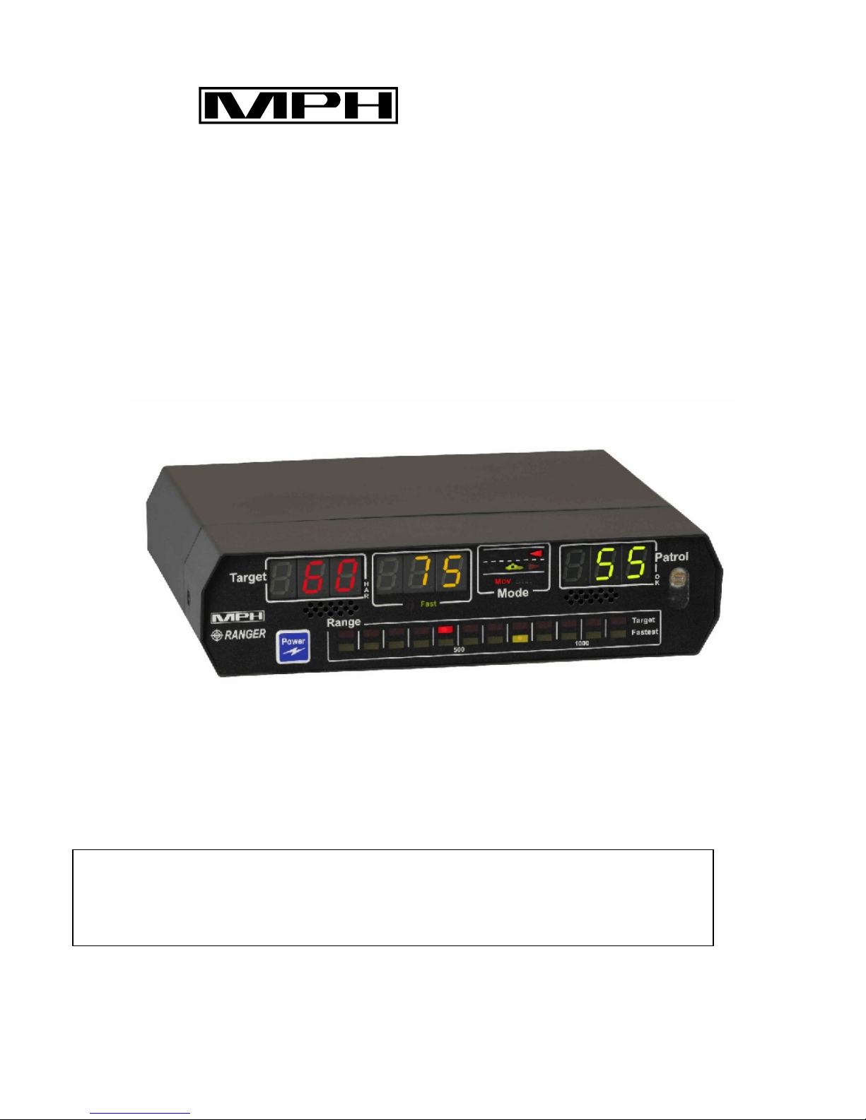
Display
The Ranger EZ uses a high contrast LED display with automatic dimming.
Target
HAR
Patrol
OK
Mode
Range
Target
500 1000
Fastest
Mode
The mode section shows what the radar is doing. The display is set up like a roadway. A large red “X” icon in
the left lane tells at a glance that the transmitter is in standby. A large green car in the right lane indicates that the
transmitter is on.
The operating mode of the Ranger EZ is illustrated with the scene of a patrol car and selected targets. In opposite
direction moving mode, the scene shows an arrow in the left lane of traffic; it is ahead of the patrol car if the front
antenna is selected and behind the patrol car if the rear antenna is selected. In same direction moving mode, the
arrows target vehicle is shown moving the same direction as the patrol car. In addition, moving mode is indicated
by “Mov” appearing under the middle speed display window.
In stationary mode, the Mode window works similarly. Indicators appear in front of or behind the patrol vehicle
icon to indicate the selected antenna. When the opposite lane of traffic is selected, only the arrow in the left lane
lights up. When the same lane of traffic is selected, the arrow in the right lane lights up. When both directions of
traffic are selected, arrows in both lanes light up. Stationary mode is indicated by “Sta” appearing below the
middle speed display window.
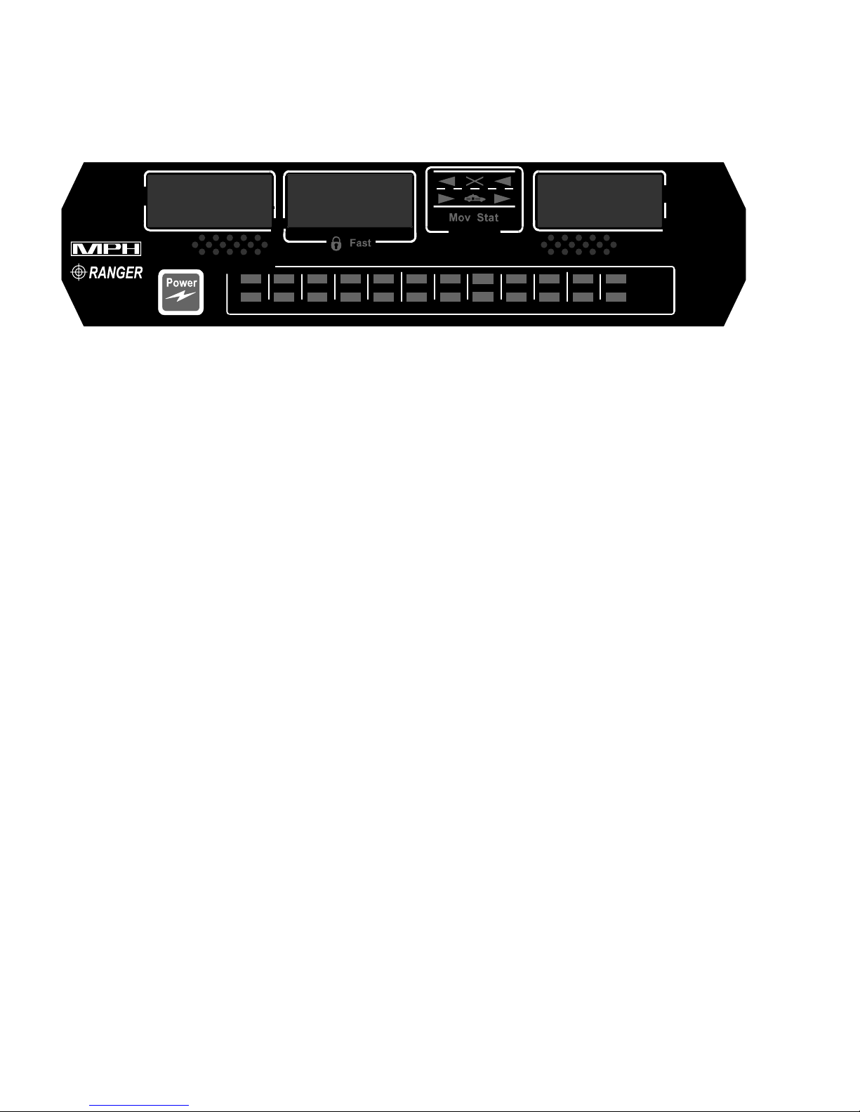
Speed windows
The Ranger EZ has three windows for speed display. These are arranged by function and use color for quick
identification at night.
The leftmost display is a dedicated red target window. This window always displays the strongest target’s speed,
even in fastest mode. This window also displays locked target speeds. If a target speed is locked, the red lock icon
under the middle window will be lit. Radio frequency error conditions (rFi) are displayed in this window.
The middle speed window is yellow and displays the fastest target speed. If the Ranger is in fastest mode, the
Fast icon below the middle window is lit. The speed of the strongest and fastest target can be locked. If the
middle window is being used to display the locked speed of the fastest vehicle the lock icon under the window
will be lit. General error conditions (Err) are also indicated in this window.
The green window on the right side of the display shows the patrol vehicle’s speed in moving mode and is unused
(filled with dashes) in stationary mode. The speed displayed in this window should always correspond with the
vehicle’s speedometer. If a low voltage condition occurs, it will be indicated in this window by “Lo” appearing in
the window.
11

Range bars
Two LED bars at the bottom of the display show the target distances of the strongest and fastest vehicles detected
by the radar. The distance bars display target distances in yards (English) or meters (Metric). As vehicles move
closer toward or further away from the patrol vehicle, the lighted segments move left or right on the display.
Each bar corresponds to 100 yards or 100 meters, depending on the unit of measure.
Doppler audio
The Ranger EZ features a speaker on the front panel for Doppler audio. The Ranger's audio is useful as an aid in
target identification. The loudness is proportional to the strength of the received signal and increases as the target
vehicle approaches. The pitch of the audio signal increases with higher speeds.
Display dimming and infrared remote sensor
A photocell is located on the display panel to automatically adjust the brightness of the display to the ambient
light conditions. An infrared sensor is also located on the display panel to receive commands from the remote
control.
Power button
This button controls the power for the Ranger EZ radar. When the Ranger EZ is turned off, the radar remembers
its user settings (volume level, mode, etc.), but it does not remember speeds and it starts up in standby mode.
When the unit is next turned on, the Ranger will be in stationary stand-by mode.
12
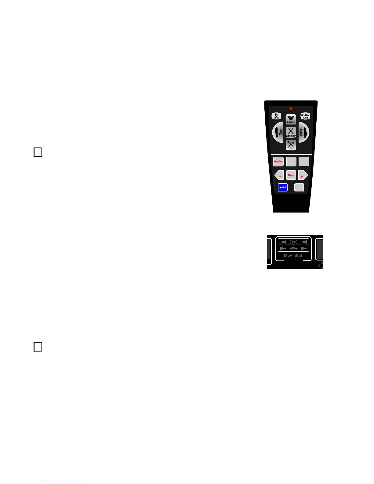
Remote Control
The Ranger EZ comes standard with a wireless remote control; however,
MPH also offers a wired version of the remote control and a rugged
motorcycle version.
The battery-powered wireless remote uses two replaceable AA alkaline
batteries, and is an infrared device; much like the one that comes with a
television. In order to get the most use out of your wireless remote please
try to avoid storing it with any buttons or keys depressed as this will drain
the batteries. In the event that the batteries are drained you may purchase
new AA batteries at any local retailer.
Both the standard wireless remote and the optional wired remote have
identical buttons and keys and neither one require any user action to power
them either on or off. The buttons and keys are separated by a heavy line in
the middle of the label.
The rugged motorcycle remote functions in the same manner as both the
wired and wireless remotes and features a metal housing. The motorcycle
remote is only available in a wired version and come with large colored
buttons for easy identification and use.
Operating mode buttons
Both the standard wireless and the optional wired remotes feature a
contoured soft raised rubber five button cluster that cradles the operators
thumb in the center cluster. This allows for easy control of the most
commonly used buttons and allows the officer to keep his/her eyes on the
road while driving. All of these rubber buttons are backlit for ease of use at
night.
Below is a short list of each buttons function:
Front: Places the radar into front antenna mode.
Rear: Places the radar into rear antenna mode.
Stndby: Places the radar into Standby.
Opp: Places the radar into opposite direction mode when moving
or stationary mode is selected.
Standard Remote
Same: Places the radar into same direction mode when moving or
stationary mode is selected.
Lock: Locks the Target speed in the Lock window.
Alert: Activates the rear traffic alert mode. (See the relevant section of this manual for more detail for this
feature.)
Motorcycle Remote
13

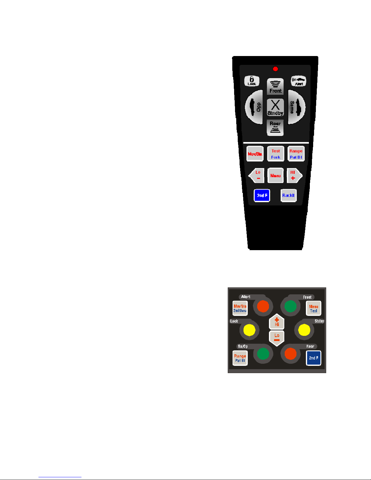
Less-frequently used keys.
These keys are flat membrane-type keys that are embossed around their edges to make them easy to identify by
feel.
Some of the keys have two colors of text identifying them. The red text is the default function of the key;
pressing the key by itself will cause it to perform this function. The function in blue text is initiated by first
pressing the blue “2ndF” key.
Mov/Sta – Toggles the radar between moving and stationary operating modes.
Test – Manually initiates a self-test of the radar.
Range – Displays the numerical range of the locked target vehicles when pressed.
Pat Bl– When the radar is in Standby mode, pressing the “2
radar to blank the patrol speed display. Pressing the key while the patrol speed display is blanked will
nd
F” key followed by the “Pat Bl” key will cause the
cause the locked patrol speed to reappear.
Low/ (-) –Places the radar in City mode, if no menu selection has been made. If a menu item has been selected it
decreases the setting of the selected menu item.
Menu – Allows the selection of modes and settings that do not have individual buttons on the remote. This is
described further in the Menu section of this manual.
High/ (+) – Places the radar in Highway mode, if no menu selection has been made. If a menu item has been
selected it increases the setting of the selected menu item.
2nd F – Allows the operator to select the blue second function of a key instead of the red primary function of the
key. “2nd” appears in the middle window when it is pressed. Pressing this key a second time causes
“2nd” to disappear and allows the radar to select the primary (red) function of a key.
Backlt – Manually causes the backlight of the remote control to turn on for 7 seconds. Once activated, the
backlight remains on for 7 seconds after any button is pressed. For wired remote control, Backlit toggles
the backlight on and off.
Main Menu Functions
Settting City or Highway Patrol mode
Highway - Pressing the “+” button places the radar in the Highway Patrol mode. The radar will momentarily
display “PtL HI” in response to the command. When the radar is in Standby, it will display “Hi” in the
Patrol window. Highway Patrol mode reduces the occurrence of “shadowing” errors at highway speeds
City - Pressing the “
–” button places the radar in the City Patrol mode. The radar will momentarily display “PtL
LO” in response to the command. When the radar is in Standby, it will display “Lo” in the Patrol
window. City Patrol mode reduces the occurrence of “combining” errors at city speeds
14

City and Highway Patrol Modes are only used when no Speedometer Interface is present, since the
Speedometer information automatically suppresses both “combining and shadowing”. If the Speedometer
Interface is present and working properly, the City/Highway setting will have no effect on the radar’s
operation.
Note: If the Menu button is pressed 4 times, the Patrol mode setting is also shown.
Adjusting the audio volume
Press the menu key one (1) time to enter the audio volume function, then press either the
lower the volume or the “
+” to raise the volume. Each press of either the “—” or the “+” key will adjust
the audio level by one. The audio volume function has 9 levels, with 0 being “mute” and 8 being the
maximum “loudest” level. During volume adjustment, “Aud” is displayed in the left window of the radar,
followed by the current setting. On subsequent power-ups, the Ranger EZ retains the volume setting it had
when the radar was turned off. A few seconds after making an adjustment, the radar will return to its
normal operating mode. Pressing the Menu key again causes the radar to move on to the squelch menu
setting.
Adjusting the squelch
Press the menu key two times (2) to enter the squelch function, then press either the
squelch off or the “+” to turn squelch on. Squelch on causes the radar to only produce an audio tone when
a target is present, while Squelch off causes the Doppler return signal to be amplified at all times. During
squelch adjustment, “SCH” is displayed in the left window of the radar, followed by the current setting
(“ON” or “OFF”). On initial power-up squelch is turned on. On subsequent power-ups, the Ranger EZ
retains the squelch setting it had when the radar was turned off. A few seconds after making an
adjustment, the radar will return to its normal operating mode. Pressing the Menu key again causes the
radar to move on to the range menu setting.
Adjusting the range
Press the Menu key three (3) times to enter the range function, then press either the “—” key to decrease
the range or the “+” key to increase the range. Each press of either the“—” key or the “+” key adjusts the
range one level. The range function has 8 settings, with 1 minimum distance and 8 being the maximum
distance. The range setting does not affect the transmitted power, only the sensitivity of the radar. During
range adjustment, “rAn” is displayed in the left window of the radar, followed by the current setting (1
thru 8). Upon initial power-up, the range is set to maximum. A few seconds after making an adjustment,
the radar will return to its normal operating mode. Pressing the Menu key again causes the radar to move
back to the city or highway patrol menu setting.
Setup Menu
The Setup menu is entered by pressing “2
items that an operator would only rarely adjust can be accessed.
If the remote being used is for a motorcycle, the set-up menu is entered by pressing 2
button. For the following section, if a motorcycle remote is used, press “2
all the setup options.
nd
F” followed by the Menu button. From this menu, a number of the
nd
Menu”, instead of Menu to go through
15
“—” key to
“—” key to turn
nd
F followed by 2nd Menu

Immediately after pressing “2
nd
F” and then Menu – Adjust the rear alert speed
This allows the operator to set the speed above which the SafetyZone rear traffic alert will warn him of
oncoming speeders (see the SafetyZone section of the manual for further details).
When setting the activation speed, the radar shows “SAF” in the left window and “SPd” in the middle
window. The number in the right window is the current alert speed threshold. Pressing “+” causes the
speed setting to increase, and pressing “—” causes the speed setting to decrease. The speed setting can
be adjusted to any speed between 30 and 90 mph.
Two presses of the menu button – Adjust the rear alert distance
This allows the operator to set the distance for which the SafetyZone rear traffic alert will warn him of
oncoming speeders (see the SafetyZone section of the manual for further details).
When setting the activation distance, the radar shows “SAF” in the left window and “dIS” in the middle
window. The number in the right window is the current alert distance threshold (in yards or meters,
depending on the units of measure). Pressing “+” causes the distance setting to increase, and pressing
“—” causes the speed setting to decrease by 20 yards or meters. The distance setting can be adjusted to
any speed between 100 and 990 yards or meters.
Three presses of the menu button – Turn automatic moving/stationary mode on or off
When the speedometer interface of the Ranger is properly installed, the radar can be programmed to
change from moving to stationary mode automatically. This menu option allows enables or disables
automatic mode switching.
The radar will show “Aut” in the leftmost window and “StA” in the middle window, followed by the
current setting for the mode (“On” or “OFF”) in the right window. To turn automatic moving/stationary
mode on, press “+”. To turn the mode off, press “—”.
Four presses of the menu button – Turn Fastest mode on or off
The radar will show “FSt” in the leftmost window, followed by the current setting for Fastest mode (“On”
or “OFF”) in the middle window. To turn Fastest mode on, press “+”. To turn the mode off, press “—”.
Five presses of the menu button – Enable fan defeat mode
The radar will show “FAn” in the leftmost window, followed by “dEF in the middle window and the
current setting for the mode (“On” or “OFF”) in the right window. To turn fan defeat mode on, press “+”.
To turn the mode off, press “—”. Fan defeat mode suppresses speed readings from very close to the
vehicle, including those readings caused by the defroster fan.
Six presses of the menu button – Selects the type of speedometer interface
This chooses the type of vehicle that the speedometer interface is attached to. When the unit is initially
delivered, the selection is “no cAr”. This means that the speedometer interface is disabled, and the setting
is used whenever the speedometer interface is not connected to the vehicle.
The following interface selections are used when the vehicle speed is sensed through the VSS signal.
Pressing “+” or “—” causes the radar to pass though its interface selection possibilities. The installed
interfaces are
16

No Car: Speedometer interface not active
Car 1: Dodge Intrepid (all) and 2004-2006 Durango
Car 2: 2000-2004 Ford Mustang
Car 3: Ford Mustang 2006 +
Car 4: Chevy Tahoe (all)
Car 5: Chevy Impala (all)
Car 6: Chevy Camaro (all) and 2500 HD pickup
Car 7: Harley Davidson (all)
Car 8: Ford Crown Victoria and Police Interceptor (all)
Car 9: Ford Explorer 2002-2004 and 2007 +, Ford Expedition 2007 +
Car 10: Ford Expedition 2004-2006 and Ford F-150 2004-2006
Car 11: Ford Explorer 2005-2006
Car 12: Dodge Charger (all)
Car 13: Dodge Magnum (all)
Car 14: Silverado
Car 15: BMW
Car 16: Ford Mustang GT 2004 and 2005
When the vehicle speed is sensed over the Control Area Network (CAN), the following selection is made,
Car 5: GM/Chevy models
Car 8: Ford Models up till 2010
Car 10: Ford Models, 2011 and above
A few seconds after making an adjustment, the radar will return to its normal operating mode. Pressing
the Menu key again causes the radar to move on to the next menu setting.
Seven presses of the menu button – Testing of speedometer interface
The radar will show “SPd” in the leftmost window, followed by “OFF”. Press + to turn the speedometer
test mode on. Then the radar will display the radar-measured patrol speed in the Patrol window and the
speedometer interface speed in the middle window. The radar will persist in this mode until one of the
antenna buttons or the standby button is pressed.
Use this mode to verify the proper operation of the speedometer interface. At a patrol speed of 40 mph,
the two speeds should match within +/- 4 mph.
Eight presses of the menu button – Radar Protocol Selection
This will select the type of serial protocol that the radar will output. Selecting “SPr 01” will output the
standard serial protocol. On pressing the “+”, “SPr 02” is displayed and the radar will output an extended
serial protocol that will include range information for target, fastest, locked target and locked fastest
vehicle.
17

Operation
Power up
When the Ranger EZ is first turned on, it will go through a complete self test. The radar will first perform a light
test, in which all of the display's indicators will light, and then the radar will perform a 32 mph internal circuitry
test. After the self-test, the current software version will be shown, followed by the current antenna configuration.
The front antenna type will be displayed, followed by the rear antenna type: “2” for a K band antenna and “0” for
no antenna.
Tuning fork tests in general
A tuning fork test is the standard test for proving that the antenna and counting unit are functioning properly. In
older analog radars, the dual tuning fork tests actually checked two different circuits, one each for patrol and
target speeds. However, the Ranger EZ uses a single circuit, the digital signal processor (DSP), to determine both
speeds, so that testing the Ranger EZ with a single tuning fork in stationary mode actually ensures that the entire
radar is working. Despite this fact, MPH recommends that you follow your court-proven department guidelines
for performing tuning fork checks.
Since the Ranger EZ is a directional radar and the tines of a tuning fork vibrate in both directions, tuning fork
tests are more complicated than they are with non-directional radars. Therefore, the Ranger EZ has a Tuning Fork
Mode, which is used while testing the radar with tuning forks. In this mode, the Ranger EZ works as a nondirectional radar, allowing the tuning forks to work properly.
Placing the Ranger EZ in Tuning Fork Mode
When a self test is performed on the Ranger EZ by pressing the Test button on the remote control, the radar does a
segment check and a 32 mph test. After this, the radar displays an “F” in the hundreds digit of the Target
window. This indicates that the radar is in Tuning Fork mode. The radar will stay in Tuning Fork mode for 30
seconds after the self test is complete.
To place the radar in Tuning fork mode for an extended period of time, press the 2
control and then the Fork button. The radar will remain in Tuning Fork mode until it is manually taken out of
Tuning Fork mode by pressing 2
Stationary mode tuning fork tests
To perform a stationary mode tuning fork test, place the radar in Tuning Fork mode and strike the tuning fork on
wood or plastic and hold the ringing fork in a fixed position two or three inches in front of the antenna with the
narrow edge of the fork facing the antenna front. This will cause the target speed window to display the speed
labeled on the fork (+ 1 mph). While performing the tuning fork test, the audio volume level may be set to a
desirable level.
Fastest mode may be tested by using the lower speed tuning fork as above and by placing the ringing higher speed
fork into the antenna beam at a greater distance since the fastest target should be a weaker signal than the target.
The Fastest button must be pressed and held on the remote. The audio will switch to the fastest target when
present. For example, for forks marked 35 mph and 65 mph, the target would read 35 (the closer fork) and the
fastest window would read 65.
nd
F button on the remote
nd
F followed by the Test button. You may need to do this to fully test the radar.
18

Moving mode tuning fork tests
Moving radar units are designed to acquire a patrol speed and look for target speeds that are faster (opposite
direction) or slower (same direction) than the patrol speed. These two speeds can be simulated using tuning forks.
The two forks are manufactured to vibrate at different frequencies. One fork will be used to simulate patrol speed
and the other target speed. In moving mode, the speed printed on the target fork will not match the speed shown
on the Ranger EZ display. It will be added to or subtracted from the patrol speed depending on the mode switch
selections.
For opposite direction moving mode, the lower speed fork will simulate patrol speed while the higher speed fork
will represent the target. For same direction moving mode, the higher speed fork will be the patrol while the
lower speed fork will be the target.
To perform the tuning fork test, place the radar in Tuning Fork mode and strike the patrol fork (lower frequency)
on a hard nonmetallic surface. Hold the ringing fork in a fixed position two or three inches in front of the antenna
with the narrow edge of the fork facing the antenna. The speed will be shown in the patrol window. While
continuing to hold the ringing fork in place, strike the other fork and hold it next to the patrol speed fork. Both
forks must be vibrating while being held an approximately equal distance from the antenna.
For opposite direction moving mode, the radar should display the low speed fork as patrol and the difference
between the forks as the target speed. For example, for forks marked 35 mph and 65 mph, the patrol would read
35 (low speed fork) and the target would read 30 (high-speed fork minus low speed fork).
19

Harmonic detection
In moving mode, the Ranger EZ receives a large reflection from the road, which is used to compute the patrol
speed. Some situations, such as when guardrails or large signs are present, cause the signal to be excessively
large. This can sometimes cause a harmonic frequency of twice the patrol speed to appear. These signals would
normally be displayed as a target with a speed equal to the patrol speed and prevent the Ranger EZ from reading
the speed of real targets, but harmonic detection circuitry inside the Ranger EZ inhibits this. Unfortunately, the
harmonic detection circuitry also may reduce the range of actual target vehicles that are moving at the same speed
as the patrol vehicle. This is normal and can be avoided by patrolling at a different speed than the offending
targets.
If Ranger EZ suspect a harmonic speed may be present, but the signal is large enough that it may be a valid target,
Ranger EZ will display the target speed but simultaneously light the HAR (harmonic) LED on the in the Target
window.
Sensitivity and radar placement
The range of the radar is influenced by how it is mounted in the vehicle. Heater fans are moving targets and will
be picked up if energy from the antenna is reflected toward the fan. Ranger EZ has special software that is
designed to minimize the effects of fan pick-up.
However, it is also important to mount the radar antennas in locations that minimize this effect. To determine this
location, place the unit in stationary mode, turn the volume up, and open the squelch. This lets any target or
interference be heard. If changing fan speeds changes the audio signal, the fan is being picked up in that
mounting position; try to find a different location. Reducing the fan speed may also reduce the problem.
Reducing the range setting of the radar will also reduce the problem. If you have persistent problems with the
RANGER EZ reading the fan speed, call the factory for suggestions specific to your particular vehicle.
Power Source
Cigarette lighter receptacles have been the traditional source of power for traffic radar. However, poor grounding,
electronic ignition bleed over, and alternator noise in newer cars can combine to create an unacceptably high level
of ambient electronic interference. In some instances, an unusually noisy vehicle ignition/alternator noise can
result in false readings and/or reduce the range of the Ranger.
If problems with EMI pick-up from the 12-Volt power are suspected, it is recommended that a shielded cable be
run from the battery directly to an auxiliary receptacle installed under the dash or on the console. This should
effectively eliminate any power source problems.
20

Maintenance
Fuse Replacement
Ranger EZ radars are shipped with a fused cigarette lighter plug. The fuse is housed inside the tip of the plug.
(See arrow in below illustration.) To remove fuse: unscrew and remove the tip and the fuse. Replacement fuses
should be commonly available 2 Amp, AGC type fuses. Substitutions are not recommended and may violate the
Ranger's warranty.
Remote control batteries
The Ranger EZ wireless remote uses 2 AA disposable alkaline batteries. These require periodic replacement by
the user. A typical set of batteries should last approximately six months, as long as the remote control is not
stored in a manner in which one of the buttons is inadvertently depressed for a significant period of time. The
first indication that the batteries need replaced will be a reduced range of the wireless remote and a need to point
the control toward the radar. In the case of totally dead batteries, the radar unit will go through its self-test when
plugged in, but not respond to commands from the remote.
The batteries are changed as follows:
• On the back side of the remote, slide the ribbed retaining latch of the battery cover down. The latch may
be difficult to slide the first few times the batteries are replaced.
• Carefully pivot the battery cover off of the remote, trying not to damage the guide hooks on the bottom of
the battery cover.
• Remove the batteries and replace them with new alkaline batteries
• Carefully replace the battery cover, inserting the guide hooks into the housing first and then pivoting the
cover back into position.
• Slide the ribbed retaining latch up to lock the battery cover.
21

FCC Licensing Requirements
The MPH Ranger EZ has a Grant of Equipment Authorization under Part 15 of the FCC rules (CFR 47). The
FCC identifier codes for the units is:
K-band CJR-RANGE-002
THIS EQUIPMENT COMPLIES WITH PART 15 OF THE FCC RULES. ANY CHANGES OR
MODIFICATIONS NOT EXPRESSLY APPROVED BY THE MANUFACTURER CO ULD VOID THE
USER’S AUTHORITY TO OPERATE THE EQUIPMENT.
22

General Operational Considerations
Understanding traffic radar
A historical perspective
The development of RADAR (an acronym for Radio Detection and Ranging) cannot be attributed to a single
inventor or even an identifiable group of inventors. Its basic concepts have been understood as long as those of
electromagnetic waves have. As long ago as 1886, it was known that radio waves could be reflected from solid
objects. Although use of a radio echo for detection purposes was discussed for many years in the literature, it
took the imminent threat of war in Europe in the late 1930's to bring about serious research and development.
The original purpose of radar was to provide advance warning of approaching enemy aircraft. Consequently, a
technique of transmitting radio waves and listening for the reflection was developed in Germany, Great Britain,
and the U.S. almost simultaneously. This search and detection system measured the length of time it took for a
reflection to come back, and from that, distance could be calculated. Using this technique, many familiar devices
were developed during the war years, often under great secrecy. These include aircraft and ship navigation, the
aircraft altimeter, and radar mapping.
With the lifting of military security restrictions in 1946, the level of research in radar declined and attention was
turned to the development of civilian applications such as radio astronomy and weather radar. Although a method
of velocity measurement using a theory of physics called the Doppler principle was well known, it was never
applied to radar until this post-war period. One of the first applications in 1948 was in primitive traffic radar to
measure the speed of autos. While these early units were an improvement over the time distance stopwatch
technique, they were bulky, difficult to operate and suffered from certain technical limitations. It was more than
twenty years before a significant breakthrough was made to enable the development of the modern-day radar as
we now know it.
The Doppler Principle
As we have seen, a wide variety of radar devices have been developed over the years to perform an even wider
variety of tasks. Let us turn our attention to how this technology is being applied to velocity measurement.
In 1842, an Austrian physicist and mathematician by the name of Christian Johann Doppler postulated a theory
that connects the frequency of a wave with the relative motion between the source of the wave and the observer.
This today is known as the Doppler principle and is used to determine the velocity of everything from a pitched
baseball to the largest galaxies in space.
An appreciation of the Doppler effect can best be gained if one considers everyday sounds produced by familiar
moving objects: the auto horn, a train whistle and a jet plane in flight will all demonstrate a marked change in
tone as they pass a stationary object. This is a result of the wave nature of sound. For example, consider the
automobile horn. The horn itself is producing waves of sound at a constant rate, say 250 waves per second. As
long as the auto is sitting still, we perceive the sound of the horn as a 250 cycle per second tone. If we next put
the auto in motion toward us at 55 mph, it becomes apparent that we no longer receive 250 waves per second at
our ear because, while the waves travel at a constant speed, each succeeding wave has a shorter distance to travel
to our ear. The waves are effectively compressed to a higher frequency per second and consequently a higher
tone is heard. The waves momentarily drop to 250 per second at a point perpendicular to the observer and then
begin to decrease in frequency as the vehicle moves away from the observer and each succeeding wave has farther
to travel to the ear. The waves are now effectively being stretched. Moreover, if the speed of the auto is
increased, so is the compression and stretching effect upon the waves and we perceive a higher and lower tone
respectively.
23

The Doppler Principle as applied to velocity measurement
Up to this point, we have been using sound to demonstrate the effects of the Doppler principle. However, as you
may know, radio energy and light also exhibit a waveform and this fact opens several interesting areas to
consideration.
As we have seen earlier, it is possible to determine the existence and the location of an object at great distance by
transmitting a beam of radio energy and then receiving that small portion of the beam that is reflected back. If it
is possible to reflect radio energy from an object, and that object is in motion toward or away from the transmitter,
the reflected radio waves should be altered in accordance with the Doppler principle. More specifically, they will
be compressed to a higher frequency as the object moves nearer to the source and, conversely, stretched as the
object moves away. Furthermore, the faster the object approaches or recedes, the greater the
compression/stretching effect upon the waves.
Therefore, if we are able to transmit a radio wave of a known frequency that travels at a constant speed, and then
construct a device to measure the frequency of the reflected waves, by comparing the two frequencies we will
know how much our beam was altered by motion, the Doppler frequency. From here, it is a straightforward
calculation to determine the velocity of our target object. This is precisely the approach taken in all modern speed
measurement devices.
Practical application of the Doppler Principle in traffic radar
Now that we have an understanding of the Doppler principle as applied to velocity measurement, let us examine
how it is used in MPH traffic radar.
You will recall in the example of the automobile horn that the frequency of the horn tone and its rate of travel
through the air were assumed to be constant, so that the only factor affecting the tone from the observer's
standpoint was the change in position of the automobile. With radio waves, we are able to assume this with much
greater confidence. For a source of radio waves, MPH has selected a sophisticated solid-state device called a
Gunn oscillator that generates radio energy in the microwave region. Specifically, a K-band radar transmits at a
frequency of 24,150 MHz, and a Ka-band radar transmits at a frequency of 33,800 MHz. This high frequency
radio energy is focused into a narrow beam and directed at the target vehicle and travels at the speed of light. A
small portion of the beam is reflected back to a second solid-state device called a mixer diode. The mixer diode
compares the frequency of the reflected beam to the transmitted frequency. The difference between these two
frequencies is called the Doppler frequency. Furthermore, the Doppler frequency is directly proportional to the
sum of the transmitter (patrol) and target velocities. It can be shown mathematically that for a transmitted K-band
frequency of 24,150 MHz, a Doppler frequency of 72.0 Hz will be produced for each mile per hour that the target
is moving. Similarly, a transmitted Ka-band frequency of 33,800 MHz will cause a Doppler frequency of 100.8
Hz to be produced for each mile per hour. For example:
K-band: 72.02 Hz x 60 mph = 4321.0 Hz Doppler frequency
Ka-band: 100.8 Hz x 60 mph = 6048.0 Hz Doppler frequency
Knowing this relationship, we are able, by means of modern electronic circuitry, to convert the Doppler frequency
as determined by the mixer diode into a digital presentation of the target's speed in miles per hour.
Some appreciation of the accuracy required of the complete system may be gained by looking at the very small
numerical value of the Doppler frequency as compared to the transmitted and received frequencies.
K-Band Vehicle Approaching at 60 mph
Reflected Frequency 24,150,004,321 cycles per sec.
24

Transmitted Frequency 24,150,000,000 cycles per sec.
Reflected Frequency 24,149,995,679 cycles per sec.
Transmitted Frequency 24,150,000,000 cycles per sec.
+ 4,321 cycles per sec.
Vehicle Receding at 60 mph
– 4,321 cycles per sec.
Note again how the reflected frequency is greater than the transmitted as the vehicle approaches and less than the
transmitted as it recedes, yet the difference, the Doppler shift, remains constant for this particular vehicle speed.
Stationary radar theory and ranging technology
Most stationary radars cannot detect what direction a target is moving. In both of the previous examples, a
“normal” stationary radar would detect a Doppler shift of 4321 cycles per second and convert that to 60 mph.
They cannot tell if the true Doppler shift was +4321 or - 4321 cycles per second.
In addition to telling the operator the exact distance of the target vehicle, MPH’s ranging technology also allows
the radar to tell the direction a target is moving relative to the radar. So in the two examples above, the radar
would see two different Doppler shifts: +4321 and – 4321` cycles per second respectively. +4321 cycles per
second would be converted to +60 mph, meaning that the target is approaching at 60 mph. - 4321 cycles per
second could be converted to -60 mph, meaning that the target is moving away at 60 mph.
This allows the Ranger EZ to do something that many traffic radars cannot do. The operator can select to only
have the radar monitor targets in a particular lane of traffic while completely ignoring traffic in the other lane.
This is particularly important when a “Jersey barrier” is present, preventing the officer from pursuing traffic in the
other lane.
Moving radar theory
Moving traffic radar refers to units that have the ability to function while the patrol vehicle itself is in motion.
They have this ability in addition to their standard stationary capabilities. When being used as moving traffic
radar, the MPH Ranger EZ will simultaneously display both the patrol vehicle speed and the target vehicle speed.
Like the stationary radar, the moving radar is based on the Doppler theory. However, with moving radar, the
signal processing is more involved than with stationary. The radar receives reflected signals from both the target
and the roadway. The target signal contains information on the combined speed of the two vehicles while the
patrol signal has the information concerning the speed of the police vehicle. The receiver (mixer diode) in the
antenna provides all of this information.
25

Operational concerns of the fastest and same direction modes
Description of the fastest mode
Historically, traffic radar has displayed the strongest target. Case law has centered on the ability of the radar
operator to confidently identify what vehicle is associated with that indication. It was relatively simple for analog
radars to process this method.
Modern DSP radars can process many targets at the same time, but there is no practical way for most of them to
display multiple targets or associate them with the correct targets (like air traffic control radar does), since the
radar only measures speed and/or direction, but not distance.
Fastest mode gives the operator an opportunity to view one other target in addition to the strongest. In this mode,
the RANGER EZ considers all possible targets in range (there may be several) and displays the strongest and
fastest ones.
Ranger EZ overcomes the difficulty in target identification associated with non-ranging radars. Ranger reports
the vehicle’s distance along with its speed, so there is little question of which vehicles are being measured, even
in traffic. With Ranger EZ, speed enforcement of the fastest target is as accurate as for the strongest vehicle. For
this reason, the Ranger EZ allows fastest targets to be locked. Fastest vehicle mode is a primary operating mode
of the Ranger.
Important points to remember regarding fastest mode:
1) Ranger EZ ’s target window always displays the strongest target in the selected direction of travel. The
middle window always displays the fastest target’s speed.
2) If the strongest target is the fastest target, the speed will not be duplicated in the fastest window.
3) In some situations, such as a car passing a large truck, the fastest target (the car) will never be the strongest
target, and with a non-ranging radar there might not have been any opportunity to lock it. With Ranger, the
fastest target can be locked in at any time, and a tracking history can be developed using the track-throughlock speed and distance information that continues to be displayed on the radar.
4) While visual identification of the strongest target is straight forward, identification of the fastest requires more
attention and information. Use the information from the Ranger’s range bar to determine the identity of the
fastest vehicle.
Description of the same direction mode
The Ranger EZ allows the tracking of targets moving in the same direction as the patrol vehicle. Because of the
Ranger EZ ’s patented Ranging technology, same direction operation requires only a little more attention from the
operator than opposite direction. The target distance information on the Range bar even makes the mode useful in
heavy traffic where visual target identification is not as easy.
26

Operation of the same direction moving mode
Same direction moving mode is selected by pressing the Same button on the remote control when the radar is in
moving mode.
Explanation of ranging technology in same direction mode.
The Ranger EZ ’s technology allows it to determine the difference between a target traveling faster or slower than
the patrol vehicle.
With Ranger’s technology, a target traveling 10 mph slower than the patrol vehicle and a target traveling 10 mph
faster than the patrol vehicle do not produce the same signal at the radar antenna. It is true that the Doppler tone
generated in the speaker by each target corresponds to 10 mph. However, the signals present in the antenna are
different.
On the front antenna, a target moving slower than the patrol vehicle is actually getting nearer the patrol vehicle,
and it produces a return signal that is at a higher frequency than the transmitted signal. Conversely, a target
moving faster than the patrol vehicle is moving away from the patrol vehicle, and it produces a return signal that
is at a lower frequency than the transmitted signal. {A rear antenna works oppositely, for example a target
moving faster is getting nearer the patrol vehicle, and produces a return signal that is higher in frequency than the
transmitted frequency, and a target moving slower is moving away from the patrol vehicle, producing a lower
frequency than the transmitted frequency.}
Ranger’s technology can tell the difference between these two frequencies (whether it is higher or lower than the
transmitted signal). The Ranger EZ then automatically determines if the target is approaching or receding, and
calculates the proper target speed. Ranger also positively identifies the target vehicle by showing the operator the
vehicle’s distance.
Important points to remember when using the same direction mode:
1) Vehicles traveling at or very near the patrol vehicle’s speed are not considered by the Ranger EZ to be targets.
Thus a vehicle may be directly in front of the patrol car, but if it is traveling the same speed (within 4 mph of
the patrol speed), it will not be a read as a target. In same direction mode, Ranger EZ displays the speed and
distance of the strongest vehicle that is has a speed difference of at least 4 mph from the patrol speed.
2) Fastest mode is available in same direction mode. The speed and distance of the fastest vehicle will be
displayed in the fastest window.
3) Sensitivity in same direction moving mode is reduced substantially from opposite direction mode. The range
adjustment does not affect the sensitivity in same direction mode.
4) Ranger has special software to defeat heater fan interference in same direction moving mode. With nonranging radars, it cannot be eliminated without sacrificing target sensitivity, but Ranger can eliminate targets
at close ranges (less than 10 yards) and eliminate all fan interference.
27

Speedometer Interface
A speedometer interface is built into every Ranger EZ radar. It is accessed through the power/signal cord of the
radar. The yellow-colored connector is used for the interface.
The speedometer interface eliminates shadowing and combining by comparing the radar patrol speed to the
speedometer. The module is connected to the vehicle’s VSS (Vehicle Speed Sensor) line, which is located in
different areas in different vehicles. Information for the installation of the speedometer interface in many police
vehicles is included in this section, but please contact MPH for the proper connection if your vehicle is not listed.
The vehicle speed information is also available through the vehicle Control Area Network (CAN). The CAN
network is accessed through the (On-Board Diagnostic connector) OBD2 connector which is typically found
under the steering column in most vehicles. MPH provides a special mating cable to connect to the OBD2
connector.
When the speedometer interface is used, the high-end speed of City/Highway mode is overridden, since the radar
has positive confirmation of the actual patrol speed. The low-end speed limit of City/Highway mode is intact, so
if you want the full speed range capability of the radar, select “Ci”.
Note: The Ranger EZ can be used without the Speedometer Interface being connected to the vehicle, and
the radar will function as normal, with the exception of Auto Stationary and Automatic City/Highway
mode.
The speedometer interface may be tested to verify its proper operation. This test is optional and is not required to
check the accuracy of the radar unit. With the speedometer interface connected to the radar, pressing the Test
button on the radar causes the patrol speed being received from the interface to be displayed in the Lock window
of the radar. The number in the Lock window should match the number on the speedometer within 2 mph. If the
patrol vehicle is stopped the lock window will read “0”. Also, if the vehicle is accelerating or decelerating, the
number may not exactly match the speedometer, since this number is updated approximately every two seconds.
28

Installation instructions for the Speedometer Interface
CAN (Control Area Network Interface)
The vehicle speed information from the CAN network is interfaced to the external world over the OBD2 (On
Board Diagnostics) port. The OBD2 port in most cases is found under the steering column of the vehicle. The 16pin OBD2 connector taps into the OBD2 port of the vehicle and the vehicle speed information is send to the radar.
In MPH radars the vehicle speed is sensed over the CAN network for the Ford and GM model vehicles only.
29

VSS Interface
Crown Victoria 2002 and up
1. Connect the universal VSS cable to the radar’s power/signal cable.
Locate the vehicle VSS wire (gray with black tracer). The VSS may be available at multiple locations in the
vehicle. If your vehicle is equipped with the optional Front Power Access connector (below left picture) the VSS
wire is located at pin 2 of this connector. The VSS signal is also available at either C175 on the power train
control module (PCM) or at C122 on the speed control actuator in the vehicle’s engine compartment (below right
picture). The VSS wire may also be accessible in the passenger floor kick panel or behind the glove compartment.
Note: A connector with blunt cut wires for accessing the VSS and
other power wires from this connector may be purchased from
your local Ford dealership. Refer to the Ford Crown Vi ctoria
Modifiers Guide available at www.fleet.ford.com for part number
and wiring information.
2. Route the blunt cut end of the universal VSS cable to where you are accessing the vehicle VSS signal.
3. Using a scotch-lock t-tap and male quick-slide terminal, connect the red wire of the VSS cable to the vehicle
VSS wire.
4. Connect the black wire of the VSS cable to a vehicle chassis ground.
5. Secure all cables and proceed to accuracy test.
30

Chevrolet Impala 2004 – 2005
1. Connect the universal VSS cable to the radar’s power/signal cable.
2. Route the blunt cut end of the universal VSS cable through the firewall into the driver’s side engine
compartment.
3. Locate the VSS wire (dark green) at Pin K of the Cruise control connector at the driver’s side wheel well area.
Note: there are two dark green wires, only pin K is the VSS signal.
4. Using a scotch-lock t-tap and male quick-slide terminal, connect the red wire of the VSS cable to the vehicle
VSS wire.
5. Connect the black wire of the VSS cable to a vehicle chassis ground.
6. Secure all cables and proceed to accuracy test.
Chevrolet Impala 2007 and newer
1. Connect the universal VSS cable to the radar’s power/signal cable.
2. Locate the 22 gauge Brown wire (VSS) in the blunt cut ignition controlled voltage and signal wires that are part
of a 5 foot wire loop located under the instrument panel in the passenger foot well. Note: The other wires in
this harness are yellow, pink and yellow/black.
3. Connect the red wire of the universal VSS cable to the vehicle’s brown VSS wire.
4. Connect the black wire of the VSS cable to a vehicle chassis ground.
5. Secure all cables and proceed to accuracy test.
Ford Mustang 2000 – 2004
1. Connect the universal VSS cable to the radar’s power/signal cable.
2. Route the blunt cut end of the universal VSS cable through the firewall into the passenger’s side engine
compartment.
Dark Green w/ whit tracer Pin 15
C108 – 2000 Mustang
C139 – 2001 to 2004 Mustang
31

3. Using a scotch-lock t-tap and male quick-slide terminal, connect the red wire of the VSS cable to the vehicle
VSS wire.
4. Connect the black wire of the VSS cable to a vehicle chassis ground.
5. Secure all cables and proceed to accuracy test.
Chevrolet Tahoe / CK Truck 2002 – 2005
1. Connect the universal VSS cable to the radar’s power/signal cable.
2. Route the blunt cut end of the universal VSS cable through the firewall into the driver’s side engine
compartment.
3. Locate the Powertrain Control Module towards the front, driver’s side engine compartment, next to the battery.
Locate the dark green wire with white tracer located at pin 50 of C2 on the PCM (see pictures next page). C2 is
an 80 pin connector. Pin 1 of C2 is a black wire with white tracer, followed by pins 2 through 40. Pin 41 of C2
is blank, followed by pin 42 of C2, which is a tan wire with black tracer, through pin 80. Note: There are
multiple dark green and white wires on Connector C2, the VSS signal is only present at pin 50.
4. Using a scotch-lock t-tap and male quick-slide terminal, connect the red wire of the VSS cable to the vehicle
VSS wire.
5. Connect the black wire of the VSS cable to a vehicle chassis ground.
6. Secure all cables and proceed to accuracy test.
32
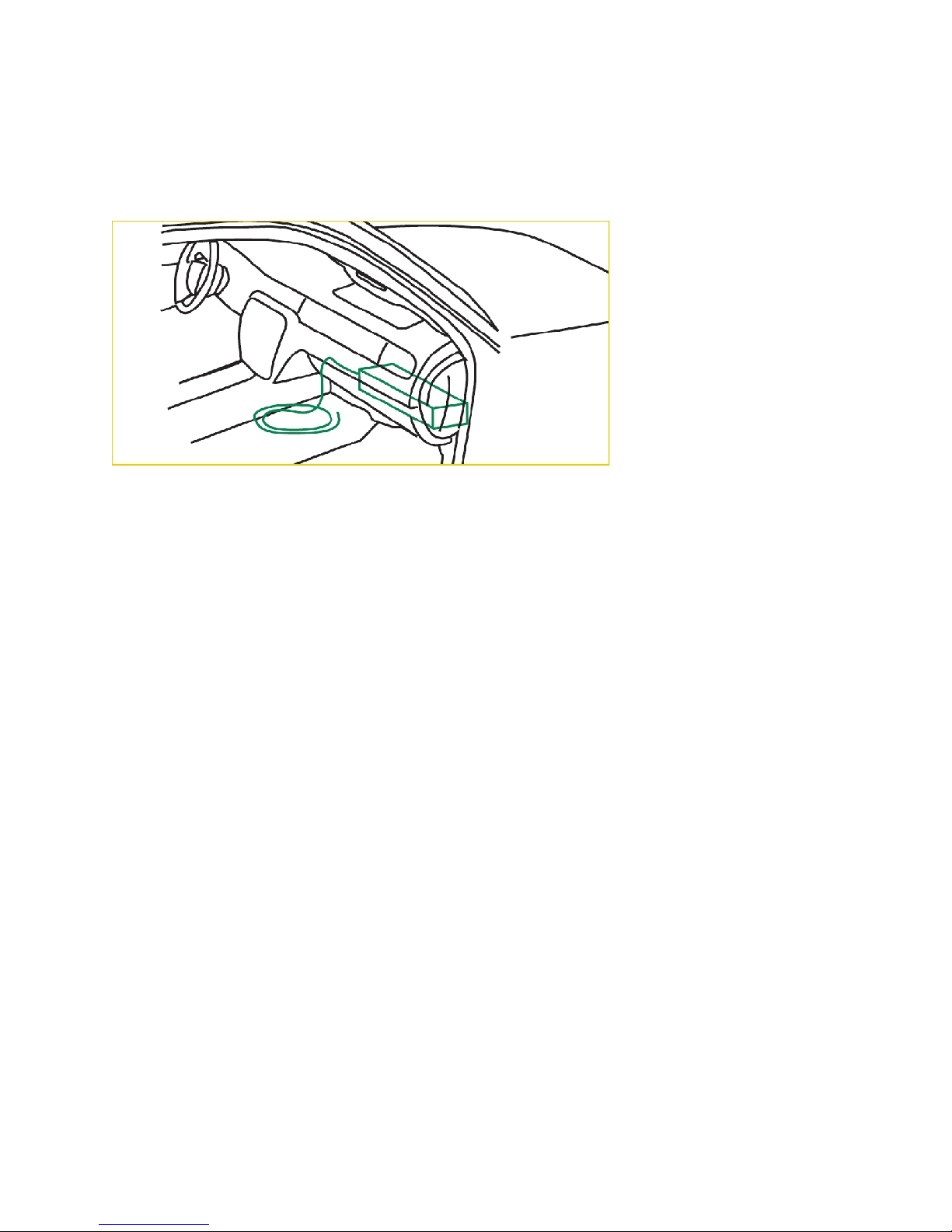
Chevrolet Tahoe 2007 – 2008
1. Connect the universal VSS cable to the radar’s power/signal cable.
2. Locate the 22 gauge Dark Green/White (VSS) in the blunt cut ignition controlled voltage and signal wires
included in a wire loop located under the instrument panel in near the center of the vehicle. Note: The other
wires in this harness are yellow, pink and yellow/black.
3. Using a scotch-lock t-tap and male quick-slide terminal, connect the red wire of the VSS cable to the vehicle
VSS wire.
4. Connect the black wire of the VSS cable to a vehicle chassis ground.
5. Secure all cables and proceed to accuracy test.
33

Chevrolet 2500HD Pickup with 4.8L, 5.3L, 6.0L and 6.2L gas engine 2008
1. Connect the universal VSS cable to the radar’s power/signal cable.
2. Route the blunt cut end of the universal VSS cable through the firewall into the driver’s side engine
compartment.
3. Connect the red wire of the MPH speedometer interface cable to the yellow/black wire on pin 57 of connector
X1 on the engine control module.
4. Connect the black wire of the VSS cable to a vehicle chassis ground.
5. Secure all cables and proceed to accuracy test.
Ford Explorer 2005-2006
1. Connect the universal VSS cable to the radar’s power/signal cable.
2. Route the blunt cut end of the universal VSS cable through the firewall into the passenger’s side engine
compartment.
3. Locate the dark blue wire with yellow tracer (2005) or yellow wire with orange tracer (2006) Output Shaft
Speed Sensor wire on Pin 3 of C175t on the Powertrain Control Module (PCM).
34
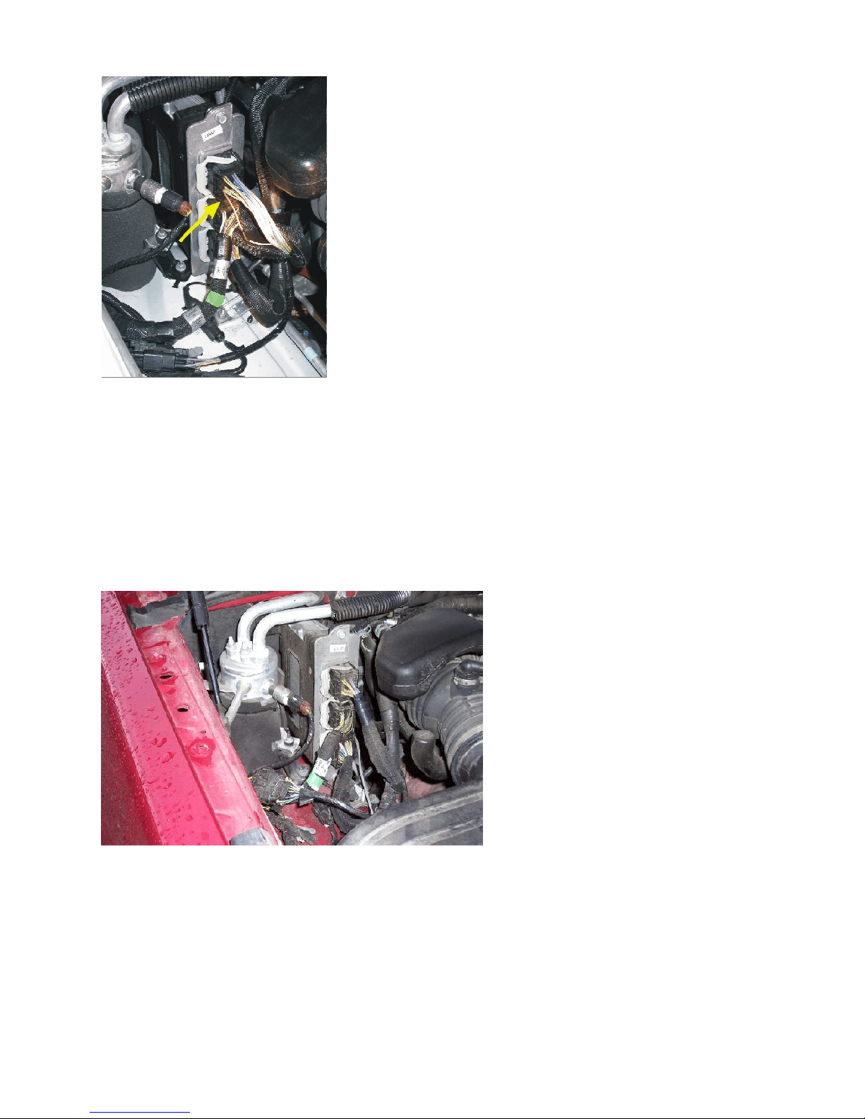
4. Using a scotch-lock t-tap and male quick-slide terminal, connect the red wire of the VSS cable to the vehicle
OSS wire.
5. Connect the black wire of the VSS cable to a vehicle chassis ground.
6. Secure all cables and proceed to accuracy test.
Ford Explorer 2007-2008
1. Connect the universal VSS cable to the radar’s power/signal cable.
2. Route the blunt cut end of the universal VSS cable through the firewall into the engine compartment.
3. Locate the violet wire with orange tracer (VS OUT) at pin 1 of connector C175B (middle connector) on the
Powertrain Control Module (PCM) at the passenger-side firewall.
4. Using a scotch-lock t-tap and male quick-slide terminal, connect the red wire of the VSS cable to the
violet/orange wire.
5. Connect the black wire of the VSS cable to a vehicle chassis ground.
6. Secure all cables and proceed to accuracy test.
Ford F-150 and Ford Expedition 2004 – 2006
1. Connect the universal VSS cable to the radar’s power/signal cable.
2. Route the blunt cut end of the universal VSS cable through the firewall into the passenger’s side engine
35
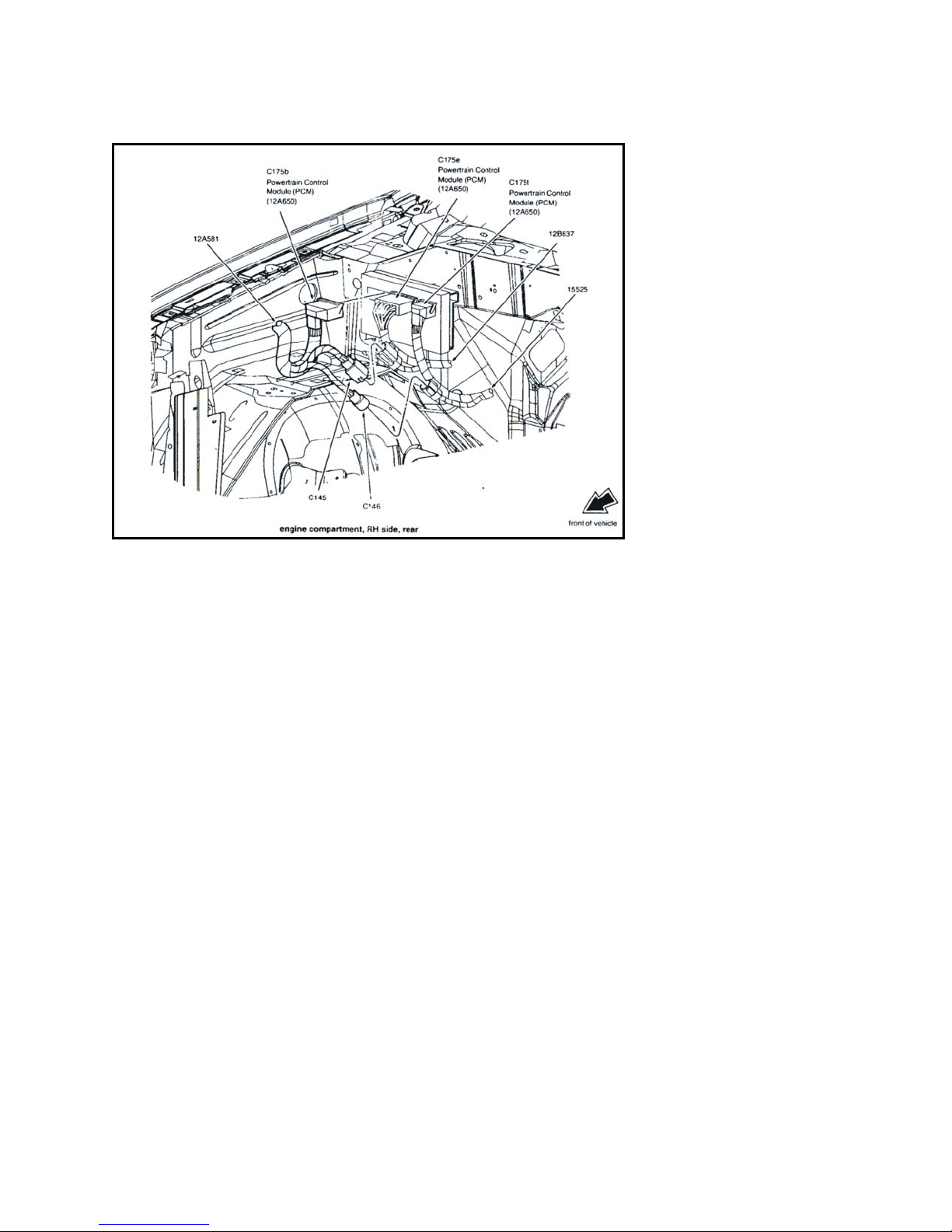
compartment.
3. Locate the dark blue wire with yellow tracer (Output Shaft Speed Sensor) on Pin 14 (2005 – 2006 Expedition),
Pin 25 (2004 Expedition) or Pin 14 (F-150) of C175T on the Powertrain Control Module (PCM).
4. Using a scotch-lock t-tap and male quick-slide terminal, connect the red wire of the VSS cable to the vehicle
OSS wire.
5. Connect the black wire of the VSS cable to a vehicle chassis ground.
6. Secure all cables and proceed to accuracy test.
Ford Expedition 2007 – 2008
1. Connect the universal VSS cable to the radar’s power/signal cable.
2. Route the blunt cut end of the universal VSS cable through the firewall into the passenger’s side engine
compartment.
3. Locate the yellow wire with blue tracer (VSS OUT) at pin 63 of connector C175B on the Powertrain Control
Module (PCM) at the passenger-side firewall.
4. Using a scotch-lock t-tap and male quick-slide terminal, connect the red wire of the VSS cable to the vehicle
OSS wire.
5. Connect the black wire of the VSS cable to a vehicle chassis ground.
6. Secure all cables and proceed to accuracy test.
36
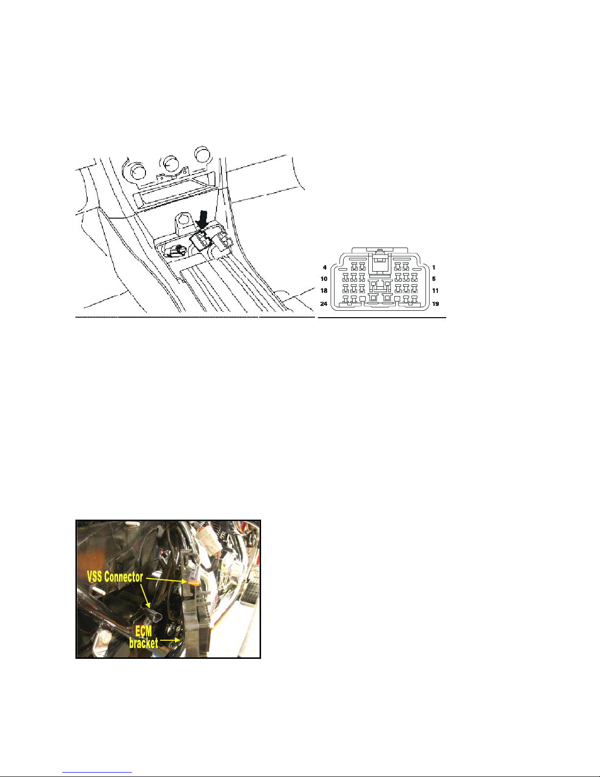
Dodge Charger 2006 and up
1. Connect the universal VSS cable to the radar’s power/signal cable.
2. Locate the police/taxi interface connector. The police/taxi interface connector is located under the instrument
panel center stack area and can be accessed by removing the plastic cover located in front of the police
equipment mounting bracket.
3. Locate the VSS wire (Brown with Dark Blue tracer) at pin 19 and the Ground wire (Black) at pin 16 of the
police/taxi interface connector.
.
4. Using a scotch-lock t-tap and male quick-slide terminal, connect the red wire of the VSS cable to the vehicle
VSS wire at pin 19 of the police/taxi interface connector.
5. Using a scotch-lock t-tap and male quick-slide terminal, connect the black wire of the VSS cable to the ground
wire at pin 16 of the police/taxi interface connector.
6. Secure all cables and proceed to accuracy test.
Harley Davidson Electra Glide and Road King 2002-2005
1. Connect the universal VSS cable to the radar’s power/signal cable.
2. Determine the appropriate area to route the cable to connect the speedometer interface to the radar, and remove
and fairings/components to facilitate routing the cable. None of the cables should be routed next to areas of
extreme heat.
3. Remove the seat and right side frame cover from the motorcycle.
4. Remove the attaching hardware for the ECM bracket (electronic control module) and pull the ECM bracket
from the frame to access the VSS (vehicle speed sensor) connector as shown in the picture below.
.
5. Unplug the VSS connector from the wiring harness as shown in the previous picture.
6. Connect the Speedometer interface VSS cable in between the motorcycle VSS connector and the motorcycle’s
wiring harness
7. Route and secure all cables and proceed to accuracy test.
37

Accuracy Test
This will determine if the radar interface is functioning properly.
1. Press “2
of Motorcycle remote, press “2
mode.
2. Hit the “+” button to activate the speedometer interface testing. The middle/fastest window shows the reading
of the vehicle speed as interpreted by the radar unit.
3. Drive the vehicle with the cruise control set or maintain a constant speed between 65 and 97 kph.
4. Compare the Patrol reading with the reading in the Fastest/Middle window (radar interface speed). If these
agree within reasonable limits (+/- 5 mph or +/- 8 kph) of each other the radar and speedometer interface are
ready to operate. (These numbers do not have to agree exactly, since the radar derives its patrol speed from
the radar beam, and the radar interface speed is used for comparison purposes only.) Return to the installation
procedure and secure all of the cables and the speedometer interface.
5. If the Patrol reading and the Fastest/middle window readings do not agree, proceed to the Speedometer
Interface Calibration Procedure.
6. To exit the test mode, press Stand-by or any transmit button on the radar.
nd
F” followed by seven presses of the Menu. This will put the radar in speedometer test mode. In case
nd
F” followed by 7 presses of the “2nd Menu” to access the speedometer test
Calibrating Speedometer Interface
In the event that you are installing the Speedometer Interface in a model and type of the car is not listed in the
Ranger EZ pre-defined speedometer interfaces, this special calibration procedure is required. The pre-defined
speedometer interfaces that the Ranger EZ uses are mentioned under “Six presses of the menu button – Selects the
type of speedometer interface” in the Remote Control section of this manual. The model and types of the
vehicles mentioned under that section do not need any special calibration procedure.
The following steps are to be followed in order to calibrate a generic speedometer interface.
1. Turn on the radar and set the radar on Stand-by.
2. Press “2
3. Press the “+” button until “cAr 99” is selected. Wait for the display to blank-out.
4. Press Front Antenna button to come out of Stand-by and go into Moving mode.
5. Ensure that the Automatic Stationary option “Aut Sta” is turned OFF.
6. Drive the vehicle at a steady speed. Variations in speed can affect the accuracy of calibration. The speed of
the vehicle has to be above 10 mph.
7. Press the following keys in sequence without allowing the sequence to time-out. The sequence is as follows,
nd
2
8. The above sequence will put the radar in Speedometer Calibration mode. The display will show “CAL ON”
on the Target and Fast window respectively. The “Lock” sign will light-up. The Patrol window will show the
patrol speed of the vehicle.
9. Press the Lock button again after 5 seconds or so. The vehicle should be going at a constant speed during this
time. “CAL ON” and “Lock” sign is blanked out and display returns to the normal mode. The speedometer
interface is now calibrated.
nd
F” and then press the Menu button six times until the display shows “No cAr”.
F Menu 2
nd
F Mov/Sta Lock.
38

10. Verify the calibration by pressing “2
nd
F” followed by Menu (OR 2nd Menu in case of motorcycle remote) 7
times, till it shows “SPd OFF”. Hit the plus sign to turn Speedometer interface ON. The reading in the Fastest
and Patrol Window should match.
In case there was an error or mistake in procedure that happened during calibration, chose the option “No Car” by
traversing the 2
speedometer interface.
nd
F menu items. After “No cAr” is selected, follow steps 3 through 9 to re-calibrate the
Safety Zone Officer Safety Alert
What Safety Zone is
Safety Zone is the first officer warning mode intended to alert an officer to the presence of a dangerous vehicle
when he is outside of his vehicle. It analyzes approaching vehicles and alerts the officer to the presence of those
who pose a threat (due to speed and or distance) and alerts the officer both inside of and outside of his vehicle.*
*SafetyZone serves as a supplement to an officer’s personal safety. While it improves the ability of the officer to safely monitor traffic
during stops, it does not fully replace the need to remain alert to the surrounding traffic
How Safety Zone detects a dangerous vehicle
When the radar is placed in Alert mode, Ranger switches to its rear antenna (if one is present) and begins
transmitting. It begins searching for vehicles in the radar beam that are traveling faster than a pre-determined
speed and are also within a pre-determined distance of the radar. Both of these factors are set using the Setup
menu. See page 17 for details.
Once the officer has programmed the radar with the speed and distance thresholds for Safety Zone alerts, the radar
will inform the officer any time that a vehicle approaches from behind traveling faster than the preset speed and
being closer than the preset distance.
The officer is alerted to the dangerous vehicle in two ways:
1. When a dangerous vehicle is detected, the face of the radar displays “THREAT” and periodically beeps.
2. If the external alarm is connected to the vehicle, the Ranger will activate the warning device that it is
connected to. In most cases, this will be the vehicle’s horn, but auxiliary horns and sirens with distinctive
tones are also available for the Ranger.
Why is speed important?
It goes without saying that a speeding vehicle is ignoring the vehicle’s emergency lights and also violating any
Move Over – Slow Down laws that are in effect.
For setting the speed threshold of Safety Zone, it is recommended that it be set to a number that is slightly higher
than the posted speed limit in order to minimize the number of alerts generated by radar. In areas where it is
mandated by law that drivers slow down in the presence of a police vehicle, the speed may be able to be set lower
than the speed limit without generating too many alerts.
The goal of Safety Zone is to warn the officer of individual vehicles that are not paying attention to his presence
and are a true danger, not for the alert to be triggered by every passing vehicle, which will desensitize the officer
to the Safety Zone alerts.
39

Why is distance important?
Trained officers know that radars can detect vehicle a long way away, based on size. A semi can be picked up at
a distance that is much farther than a motorcycle, for example.
Without distance information, SafetyZone would be in danger of alerting the officer to far-away large vehicles
rather than those that are close and pose a real danger. A far-away semi may slow down long before it nears the
patrol vehicle and not be a real threat. Distance (range) information minimizes the number of false alerts
generated by Ranger.
When setting the distance for the SafetyZone alert, the officer is advised to choose a distance that will give
sufficient warning for him to take evasive action in the presence of dangerous vehicles but will not trigger the
alert for vehicles a long distance away. The following chart will assist in the selection of the alert distance:
Vehicle distance in yards
Speed
35 mph 2.9 sec 5.8 sec 8.8 sec 11.7 sec 14.6 sec 17.5 sec 20.5 sec 23.4 sec
40 mph 2.6 sec 5.1 sec 7.7 sec 10.2 sec 12.8 sec 15.3 sec 17.9 sec 20.5 sec
45 mph
50 mph
55 mph 1.9 sec 3.7 sec 5.6 sec 7.4 sec 9.3 sec 11.2 sec 13.0 sec 14.9 sec
60 mph 1.7 sec 3.4 sec 5.1 sec 6.8 sec 8.5 sec 10.2 sec 11.9 sec 13.6 sec
65 mph
70 mph
75 mph 1.4 sec 2.7 sec 4.1 sec 5.5 sec 6.8 sec 8.2 sec 9.5 sec 10.9 sec
80 mph 1.3 sec 2.6 sec 3.8 sec 5.1 sec 6.4 sec 7.7 sec 8.9 sec 10.2 sec
85 mph 1.2 sec 2.4 sec 3.6 sec 4.8 sec 6.0 sec 7.2 sec 8.4 sec 9.6 sec
90 mph
50 yds 100 yds 150 yds 200 yds 250 yds 300 yds 350 yds 400 yds
2.3 sec 4.5 sec 6.8 sec 9.1 sec 11.4 sec 13.6 sec 15.9 sec 18.2 sec
2.0 sec 4.1 sec 6.1 sec 8.2 sec 10.2 sec 12.3 sec 14.3 sec 16.4 sec
1.6 sec 3.1 sec 4.7 sec 6.3 sec 7.9 sec 9.4 sec 11.0 sec 12.6 sec
1.5 sec 2.9 sec 4.4 sec 5.8 sec 7.3 sec 8.8 sec 10.2 sec 11.7 sec
1.1 sec 2.3 sec 3.4 sec 4.5 sec 5.7 sec 6.8 sec 8.0 sec 9.1 sec
Table 1: Alert time vs. detection distance and vehicle speed
Difference between SafetyZone and IACP-prohibited “Speed Monitor Alerts”
When SafetyZone is started, any locked speed information that is contained on the face of the radar is preserved,
but in SafetyZone mode, the radar ceases to display new target speeds. This is done so that SafetyZone cannot be
used as a “speed monitor alert” as defined by the International Association of Chiefs of Police.
To quote their definition of speed monitor alert, it is “a function that alerts the operator when a target speed signal
is received that is equal to or above a pre-selected threshold speed” so that an officer can take enforcement on that
vehicle without developing a proper tracking history. The IACP’s Enforcement Technology Advisory Technical
Subcommittee (ETATS) allows speed measurement devices to contain safety alerts like SafetyZone as long as the
alert does not report the vehicle’s speed to the officer when it is triggered. Also, to comply with the IACP
guidelines, if the officer chooses to exit SafetyZone mode while it is displaying an active threat alert, the
transition to normal speed measurement mode will be inhibited until the threat has passed, further inhibiting
SafetyZone from being used as a “speed monitor alert”.
When the Ranger reports a “THREAT” condition, the horn or an auxiliary sounding device will start beeping. Once the
officer has acknowledged the threat, pressing any of the buttons on the keypad will set the unit in Rear-Alert Stop mode. This
is indicated by “RAL StP” (Rear Alert Stop) message on the display. This message will stay on as long as there is a threat. To
set the Ranger in the normal operating mode, any of the transmit keys (Front Antenna, Rear Antenna or Stand-by) have to
pressed. If any other key has been pressed, the Ranger stays in Rear Alert Stop mode with “RAL StP” displayed.
A simple way to state this is that speed alerts which only alert the officer to a dangerous condition are allowed,
but speed alerts show the officer the speeds of speeding vehicles for enforcement reasons are not allowed.
40

Connection of the Ranger to the vehicle’s horn
1. Locate the SafteyZone cable of the Ranger. Depending on the Ranger model, the cable either attaches to
a circular connector on the rear of the counting unit or it connects to the Ranger’s Power/Signal cable.
Connect the cable to the Ranger.
2. Locate the one of the horn activation wires of the vehicle. This can either be a horn wire in the steering
column, or it may be more convenient to attach to it at the vehicle’s fusebox. This wire should be on the
“low” side of the horn relay, which runs between the horn relay and the horn switch in the steering
column.
3. Verify that you have the proper wire by conducting the following test:
a. Monitor the voltage on the wire without the horn being activated. The voltage should be
approximately 12 volts, pulled up to 12 volts by the horn’s relay coil. The key may have to be in
the ON or Accessory position to have voltage to the horn circuit.
b. Activate the horn. Verify that the voltage on this wire is pulled to ground (0 Volts).
4. Connect the black wire of the SafetyZone cable to the vehicle’s ground in the vicinity of the place where
you will connect to the horn circuit.
5. Connect the red wire of the SafetyZone cable to the horn circuit in the place you identified in a) and b)
above using a T-tap or other method that does not hurt the integrity of the horn connection. Do not sever
the vehicle’s horn wire.
6. Test the SafetyZone using one of the tuning forks supplied with the Ranger.
a. Set the SafetyZone alert speed to a speed that is lower than the tuning fork’s speed.
b. Set the SafetyZone alert distance to 100 yards.
c. Enable SafetyZone by pressing the Alert button on the remote control.
d. Ring the tuning fork in front of the radar’s rear antenna and verify that the horn of the vehicle is
sounded when the radar shows the “THREAT” alert message on its face.
7. Change the SafetyZone speed and distance settings to a level that is consistent with the areas where
speeds are anticipated to be enforced.
Connection of Ranger to an auxiliary alert device
To connect the SafetyZone alert of the Ranger to an auxiliary alert device (horn, siren, etc.), consult the
instructions supplied with the device.
41

Interference Information and Precautions
There are several factors that can influence the operational behavior of Doppler radar. These influences can be
natural or man-made. A knowledgeable operator will not be confused by these external influences.
1. Natural Influences
Driving rain or blowing dust can cause a scattering effect, or diffusion, which can decrease the effective
range. A driving rainstorm may affect the patrol display. Close observation of the patrol vehicle speed is
recommended.
Terrain can affect the range. If the patrol car is on a slight decline, the antenna could be shooting short of
the target vehicle. If on a slight incline, it could be shooting over the target vehicle. The distance at
which the radar can detect vehicles may be shortened in either case.
Strong reflectors can cause target readings that are the same as the patrol speed when in the moving
mode. To avoid this problem, the Ranger EZ detects these harmonics and inhibits their display.
Note: The harmonic detection feature may cause occasional blanking of legitimate target speeds when it
is the same as the patrol speed, or a multiple of it. If the operator suspects this is the case, he can change
his speed. In any case, the range of any other target is not changed; for example, if the closest target is
blanked due to the coherence detector, the Ranger EZ will not acquire and display a weaker, more distant
target in its place.
2. Man-made Influences
These influences are normally the most troublesome because they generally involve electronic signals that
may cause spurious displays, or they may lessen the effective range.
Power transformers, radio transmitters, neon lights, etc. generate electronic noises. These influences
generate a phenomenon that can cause radar to display a false reading or lessen the effective range. The
RFI indicator will show the presence of strong RF fields caused by local transmitters. To prevent
possible readings caused by the interference, no target speed will be displayed when this indicator is on.
Intermittent signals may also be caused by electrical noise produced by the vehicle’s ignition system or by
vehicles with noisy alternators. The RFI detection circuitry will recognize this noise as well and suppress
the speed readings. However, the officer needs to be aware that these sources of electrical noise may
affect the operation of the radar.
All radar speed measurement devices are sensitive to objects that move or vibrate in front of the antenna.
In instances where the antenna is pointed in the general direction of the fan, or where the radar beam is
reflected by the glass towards the heater/defroster fan, the radar may read the speed of the fan. Reading
the fan speed is annoying and, in some cases, can reduce the effective range of the speed measurement
device.
Ranger EZ includes a fan-defeat mode in which the radar will ignore targets that are within 10 yards of
the radar. This effectively inhibits readings from the defroster fan.
Intermittent readings need not be confusing if the officer is familiar with the operation of the Ranger EZ.
MPH Industries suggests the following if fan interference is suspected:
42

1. First, determine the fan is the source of interference by checking whether the readings
change when the fan is turned off or when the fan speed is increased or decreased.
2. Engage the fan-defeat feature. This should eliminate the problem in most cases.
2. If the problem persists, reduce the effects of the fan by locating the Ranger EZ antenna in
an area that is less susceptible to the fan motion. MPH Industries provides several
mounting options. In some cases, the left-hand corner of the dash has been found to be
the best mounting location. Alternately, the antenna may be mounted outside of the
patrol vehicle.
43

Legal guide
The Ranger EZ Doppler radar is based upon the well-known and legally accepted Doppler principle of operation.
Because of its accuracy and wide legal acceptance over the years, most citations based on Doppler radar now
result in guilty pleas.
The arresting officer does need to acquaint himself, however, with the basic case laws regarding radar and make
sure that he performs certain guidelines to meet these precedent cases. Brief descriptions of the more important
landmark cases are listed below. Much of the referenced material may be obtained at your local law library or
prosecutor's office.
Reference A
- 7 AMJr2d 870 (Sec. 327)
A legal encyclopedia dealing with automobiles and highway traffic, which describes the conditions under
which evidence of excessive speed determined by the use of radar may be admitted.
Reference B -
49 ALR2d 469 and Cumulative Supplements Thereto
A legal publication reporting the Dantonio case (1955) and briefing it and subsequent cases dealing with
proof, by means of radar devices, or violation of speed regulations.
Reference C -
State v. Dantonio (NJ), 115 A2d 35, 49 ALR2d 460
A landmark case on the subject. This case sets precedent of the following:
1. Judicial notice has been taken of the accuracy of radar.
2. A few hours training is sufficient to qualify an operator.
3. The operator need not understand, or be able to explain, the internal workings of the radar.
Reference D -
Establishes that the court may take judicial notice of the reliability of radar.
Everight v. Little Rock, Ark., 326 SW2d 796
Reference E -
State v. Graham, Mo., 322 SW2d 188
Establishes that the court may take judicial notice of the ability of radar to measure speed.
Reference F -
State v. Tomanelli, Conn., 216 A2d 625
Reviews the matter of judicial notice, and recognizes the ability of Doppler radar to measure the speed of
a motor vehicle, and that the tuning fork is a reliable accuracy test.
Reference G -
Honeycutt v. Commonwealth, Ky., 408 SW2d 421
In this appeal, the court rejects the arguments of the appellant that the evidence should not have been admitted and
again establishes that: 1). A properly constructed and operated radar device is capable of accurately measuring
the speed of a motor vehicle; 2). The tuning fork test is an accurate method of determining the accuracy of a radar
unit; 3). It is sufficient to qualify an operator who has knowledge and training which enables him to properly set
up, test, and read the radar; 4). It is not required that the operator understand the scientific principles of radar or
be able to explain its internal workings, and that a few hours of instruction normally should be enough to qualify
an operator; 5). The officer's estimate of excessive speed from visual observation, when confirmed by the reading
of the radar device and when the offending vehicle is out front, by itself, nearest the radar, is sufficient to identify
the vehicle if the observations support the radar evidence.
From the case law, the officer needs to know and to be able to testify to the following points to have a
successful prosecution:
44

1. The officer must establish the time, place, and location of the radar device; the location of the
offending vehicle when the offence took place; that the defendant was driving the vehicle; and
that State law regarding the posting of speed limits and radar signs had been complied with.
2. The officer must state his qualifications and training.
3. The officer must establish that the radar device was operating normally.
4. The officer must establish that the radar was tested for accuracy, both before and after its use,
using a certified tuning fork or other accepted method.
5. The officer must accurately identify the vehicle.
6. The officer must have seen that the vehicle appeared to be speeding and estimated how fast.
7. The officer must have gotten a radar speed-reading that agreed with the visual estimate of the
target vehicle's speed.
8. If a Doppler audio feature is present on the radar device, the officer is strongly encouraged to
establish that the audio Doppler pitch correlated with both the visual speed estimate and the radar
reading.
9. If moving radar is used, the officer must testify that the patrol speed indicated by the radar was
verified against the speedometer at the time the speed measurement was obtained.
In addition, MPH recommends that the vehicle’s distance as indicated on the Ranger EZ be compared with the
officer’s estimate of the vehicle’s distance. As the vehicle is tracked, the speed should be consistent (not erratic)
and the distance of the vehicle progressively move along the Range bar.
45

Ranger EZ Accessories
Certification services
The Ranger EZ is provided with a certificate of calibration for the radar and a pair of certified tuning forks. The
Ranger EZ should be periodically recertified per your state or department's guidelines. The MPH Service
department offers a certification service for all MPH radars and tuning forks. Contact the Service department at
(888) 689-9222 for more information.
Carrying case
A carrying case made of durable high-impact plastic is available for the Ranger EZ. In addition to holding the
radar, space is provided for storing the radar's tuning forks, mounting bracket, and operation manual.
Replacement or additional remote controls
The remote control is not programmed to work with a specific Ranger EZ radar; any Ranger EZ remote will work
with any Ranger EZ. For this reason, it may be desirable to order a few spare remote controls, especially in
scenarios where loss is more likely; for example if the Ranger EZ will be shared between patrol vehicles or if it
will be used on a motorcycle.
Wired Remote Control
A wired version of the remote control is available as an option. The wired remote control can be used in
conjunction with or as a replacement to the wired remote.
Mounting brackets
A variety of mounting brackets is available for the Ranger EZ. These include brackets for most models of law
enforcement vehicles and brackets for mounting the Ranger EZ on motorcycles.
Service Manual
Copies of the comprehensive service manual for the Ranger EZ may be ordered from MPH by authorized service
centers and select law enforcement agencies. As a rule, service manuals are not made available for sale to the
general public.
Operation Manual
A copy of this Ranger EZ operation manual is provided with each Ranger EZ purchased. Owners of the Ranger
EZ, law enforcement agencies, and their affiliates can order additional copies of the operation manual from MPH.
As a rule, operation manuals are not made available for sale to the general public.
Replacement tuning forks
A pair of certified tuning forks (20 mph and 50 mph) is provided with each Ranger EZ purchased. Replacement
tuning forks can be ordered from MPH.
Motorcycle model
A version of the Ranger EZ is available that is tailored for motorcycle use. It includes a waterproof display unit, a
waterproof, wired remote control, and the standard waterproof antennas. It is designed for permanent mounting to
the motorcycle. The wired remote control is designed to be easily operated while the motorcycle is being driven.
Mounting brackets are available for mounting the display, antennas and remote control on the motorcycle.
46

Quality Control Procedures and Repair of the Ranger
Quality control procedures
All Ranger EZ traffic radars comply with the following quality control conditions:
1. All parts and components are ordered to commercial high reliability, accuracy, and performance
specifications.
2. Only vendors that meet MPH’s standards for quality are selected to supply parts and materials.
3. All electrical and electronic components are utilized within their performance specifications, and adequate
safety factors measures are provided for voltage, current, and heat dissipation.
4. Assembled circuit boards are individually tested before incorporation into higher level assemblies.
5. Each traffic radar is tested in an anechoic chamber for proper performance and compliance to accuracy
requirements.
6. Each radar is tested (“burned-in”) for not less than twelve hours. After completion of burn-in testing, the unit
is again tested in the anechoic chamber to assure product excellence.
7. Each radar is road tested under conditions encountered in actual operation.
8. Tuning forks are individually tested using calibrated equipment with traceability to the National Institute of
Standards and Technology. A certificate of accuracy is furnished with each tuning fork.
9. Samples of police traffic radars on the Consumer Product List (CPL) are tested by outside laboratories for
compliance to the requirements specified for Critical Performance Testing (CPT) by the International
Association of Chiefs of Police (IACP).
47

Servicing the Ranger
Product repair during the warranty period
All warranty repair of the Ranger EZ will be performed by MPH's service center unless written permission has been
granted otherwise by MPH. Contact the factory for authorization and shipping instructions to return any product
considered to be covered by the manufacturer's warranty.
Product repair outside of the warranty period
MPH suggests that the repair of Ranger EZ radars outside of the warranty period be performed by MPH's service center
because of its expertise in handling Doppler radar problems. All factory repairs are guaranteed by MPH as detailed in the
Ranger EZ warranty. Consult the factory for repair procedures and charges.
The user is particularly advised to return the Ranger EZ to MPH for repair whenever an antenna problem is indicated.
A large portion of the expense of the Ranger EZ is contained in the antenna assembly. Also, the microwave
frequencies used by the antenna require the use of specialized test equipment that is not available to the typical
technician. Furthermore, federal law dictates that any adjustments to the transmitter are made under the supervision
of a FCC-licensed technician. MPH has more than thirty years of experience servicing Doppler radar antennas.
Statement of Product Warranty
MPH Industries, Inc. warrants that the Ranger EZ will be free from defects in material and workmanship, under
normal use and service, for a period of one year from the date of invoice to the original purchaser. Extensions of this
product warranty may be purchased from MPH. MPH's obligation is limited to repairing or replacing, as MPH may
elect, any part or parts of the Ranger EZ that MPH determines to be defective in material or workmanship. Warranty
repair will only be performed at MPH's service center.
Radars considered to be covered by the conditions of this warranty shall be returned, freight pre-paid, to MPH. The
repaired or replaced product will be returned from MPH pre-paid.
Warranty coverage extends only to the original purchaser and does not include normal wear and tear, unusual abuse,
or the use of the product for other than its intended purpose. This warranty is voided if the Ranger EZ is adversely
affected by attaching any feature or device to it, or is in any way tampered with, modified or opened without express
written permission from MPH.
There are no warranties expressed or implied, including but not limited to, any implied warranties of merchant-ability or any
indirect or consequential damages arising out of any such defect in material or workmanship.
As a further limit on warranty and as express warning, the user should be aware that harmful personal contact may be
made with the seller’s product when it is used in automobiles in the event of violent maneuvers, collision, or other
circumstances, even though said products are installed according to instruction. MPH specifically disclaims any
liability or injury caused by the products in all such circumstances.
Repaired products for which the original warranty has expired are warranted for 90 days from the date of repair,
subject to the same conditions as the original warranty.
48

Return Policy
Customer satisfaction is very important to MPH Industries. It is MPH Industries’ policy and objective to allow
prospective purchasers ample opportunity to become familiar with our products prior to purchase. We do so
through our product rental and demonstration programs.
MPH Industries is committed to designing and manufacturing our products to the highest standards of quality and
reliability. We offer a limited warranty that covers all materials and workmanship. Details of the warranty are
found in the Statement of Warranty in the Operator’s Manual.
We do not want customers to incur unreasonable inconvenience due to equipment failure. MPH Industries will
replace any MPH product or make a full refund if repairs cannot be made within the initial 30 days of ownership.
If replacement if offered or repair can be made, but the customer insists on returning the product within this initial
30 day period, a 15% restocking fee will be assessed.
After the initial 30 day ownership period, MPH Industries will honor its warranty through either the repair or
replacement (MPH’s discretion) of the malfunctioning product during the warranty period.
49

MPH Ranger EZ Specifications
The MPH Ranger EZ is designed for convenient use by law enforcement agencies to measure the speed of
motor vehicles when operated from a moving or stationary patrol vehicle. The Ranger EZ utilizes the
well-known and legally accepted Doppler principle and has been type accepted by the Federal
Communications Commission.
A. SYSTEM SPECIFICATIONS
Front antenna “on”, no target (0.4A typical)
Front antenna “on”, with target (0.5A typical)
Front antenna “on”, during LED test (0.7A typ.)
Nominal Power Supply Voltage: 13.6 Vdc
Low Voltage Condition Level: 10.8 Vdc. When supply voltage decreases below
this, a message of “Lo” is displayed on the front
panel to warn the officer of a low voltage
condition.
Power Requirements & Voltage: 10.8 Vdc-16.5 Vdc (13.6 Vdc Nominal)
Current draw at 13.6 Volts: Standby, no displays (0.3A typical)
Stationary Operating Speed: Stationary mode operating speed range is from 15 mph up to 200
mph.
Moving Operating Speed: Patrol Speed range is 20 mph to 100 mph in highway mode and 12
mph to 80 mph in city mode. (When the speedometer interface is
active, the patrol speed range is extended to 120 mph.)
In opposite direction mode, Target Speed range is 12 mph up to a
closing speed of 200 mph.
In same direction mode, Target Speed range is patrol speed ±70%.
There must be a minimum difference of 4 mph between target and
patrol speeds. Same direction targets will not be displayed unless
the patrol speed is at least 20 mph.
Operating Temperature Range: -30°C (-22°F) to 60°C (+140°F)
Operating Humidity Stability: Operates normally up to at least 90% relative
humidity at 99°F (37°C).
Automatic Performance Check: The radar automatically and invisibly checks itself for proper
operation. If an error is detected, the fault is indicated in the
middle window. Proper operation is indicated by the OK light.
50

B. DISPLAY UNIT
Speed Display: Three windows for LED speed display on Lexan scratch resistant
Speed Display Windows: Target Speed (red, on the left side of the display)
Mode Window: Roadway-type display. Includes
Switches: Power
Physical Size: Depth = 1.7”
Width = 6.5"
Height = 1.7"
Range displays Two LED bar graphs to inform user of target distances. Each segment
Other Indicators: Fast (fastest vehicle mode)
Connectors: Counting unit (15-pin male)
front panel. LED displays automatically adjust brightness to
ambient conditions.
Fastest Target Speed (yellow, in middle of display
Patrol Speed (green, on the right side of display)
of the display corresponds to 100 yards of distance
A car, which lights whenever the radar is on
An “X” that lights whenever the radar is in Standby
Four directional arrows that indicate the area(s) from which
speeds are being measured Moving mode indicator
Stationary mode indicator
Lock (locked speeds)
OK (unit is functioning properly)
HAR (the target speed is a harmonic of the patrol speed)
51

C. COUNTING UNIT
Physical Size: Depth = 3.8”
Width = 6.5"
Height = 1.7"
D. REMOTE CONTROL
Data link: Standard: Serial data stream via infrared light link.
Optional: Serial data stream via cable.
Power: Cordless: Two AA alkaline batteries
Corded: Not applicable
Raised, shaped keys: Front antenna
Same direction
Backlt (backlight)
Physical Size: Width = 2.4" at top
Height = 5.5"
Depth = 1.3"
Connectors: Front antenna
Rear antenna
Display unit (DB-15)
Power/Accessory Cable
Power cord (cigar plug)
RS-232 data port (DB-9)
Speedometer (4-pin connector)
Wired remote (3-pin connector)
Safety Zone alert (circular connector)
Backlighting: Cordless: Activated for 7 seconds when Backlt button is pressed.
Flat panel keys: Primary function
Once activated, stays on for 7 seconds after any button is pressed.
Corded: Turns on when radar is powered on. Successively deactivated
and reactivated with Backlt button.
Rear antenna
Standby
Opposite direction
Lock
Fastest
Mov/Sta (moving/stationary)
Test (normal self-test)
Alert (Rear alert)
– (decrease the current menu item)
Menu (operational menu)
+ (increase the current menu item)
2nd F (access secondary functions)
1.5” at base
Secondary function (w/2
Fork (tuning fork test)
Pat Bl (patrol speed blank)
Same as primary function
Setup (Setup menu)
Same as primary function
nd
F)
52

E. ANTENNA UNIT
Circularly polarized antenna operating in the K band. All electrical components are enclosed in a sealed
metal housing to defeat radio frequency interference. Metal housing has a black polycarbonate radome
(housing) over it to protect the internal components, including the antenna lens, from physical damage and
from damage from the elements. Plastic housing creates a waterproof O-ring seal, allowing all-weather
operation outside of the patrol vehicle. Has aiming sights.
Operating Frequency: K band: 24.150 GHz + 100MHz
Microwave Source: Solid-state Gunn effect diode.
Output Power: Nominal 12-30 mW / Maximum 50 mW
Radiated Power Density: Less than 2mW/cm
Type: Circularly polarized conical horn
Beam Width: 13° Nominal
Beam Width Variance: +1° at maximum manufacturer's tolerance
Side Lobe: 22 dB down from main beam maximum
Transmitter: Complies with FCC Part 15
FCC Type Acceptance: K band CJR-RANGE-002
Physical Size: Length: 4.63” (11.8 cm)
Diameter: 2.75” (7 cm)
2
at 5 cm.
3.38” (8.6 cm) at waterproof seal)
53

Operational Recommendations
Subsequent to an August 1992 Congressional hearing convened by Senator Joseph Lieberman of
Connecticut on the safety of police traffic radar devices, the U.S. Congress directed the National
Institute for Occupational Safety and Health (NIOSH) to study the cancer incidence among law
enforcement officers who had used traffic radar devices.
In June 1995 NIOSH issued a report titled Occupational Exposure of Police Officers to
Microwave Radiation from Traffic Radar Devices describing their findings, including an
exposure assessment, an analysis of existing record sources, and a summary of their
recommendations. The report concluded that there was not a sufficient basis to identify health
risks to humans, although the possibility could not be ruled out. The following are quoted
directly from the report and are procedures that are recommended to reduce or prevent exposure
to microwave energy emitted from traffic radar devices. The Ranger EZ fully conforms to all of
these guidelines.
1. When using two-piece radar units, the antenna should be mounted so that the radar beam
is not directed toward the vehicle occupants. The preferred mounting location would be
outside the vehicle altogether, although this may not be practical with older units that
cannot withstand adverse weather conditions. Other options, e.g., mounting on the
dashboard of the vehicle, are acceptable if the antenna is at all times directed away from
the operator or other vehicle occupants. However, the antenna must be installed to
provide a separation of at least 40 cm from all persons and must not be co-located or
operating in conjunction with any other antenna or transmitter.
2. Radar antennas should be tested periodically, e.g. annually, or after exceptional
mechanical trauma to the device, for radiation leakage or back scatter in a direction other
than that intended by the antenna beam pattern.
3. Each operator should receive training in the proper use of traffic radar before operating
the device. This training should include a discussion of the health risks of exposure to
microwave radiation and information on how to minimize operator exposure.
54

Part No. 991075, Rev E
Date: Dec. 2011
®
MPH INDUSTRIES, INC.
A SUBSIDIARY OF MPD, INC.
316 EAST NINTH STREET
OWENSBORO, KY 42303
1-888-689-9222
FAX: (270) 685-6288
55
 Loading...