

Industries
BEE III
Automatic Same Direction
(Canadian Version)
TM
TM
Traffic Radar
Operation Manual

We at MPH Industries thank you for purchasing our equipment. We wish you
2
the greatest success in your speed enforcement program. We are proud that
the BEE III is a part of your department.
Copyright 2001-2013, MPH Industries, Inc.
No part of this work, covered by the copyrights hereon, may be reproduced or copied in any
form or by any means – graphic, electronic, mechanical, including photocopying, taping, or
information storage and retrieval systems – without the written permission of MPH Industries,
Inc.
BEE III, Automatic Same Direction, ASD, MPH Industries, the MPH logo, and POP are
trademarks of MPH Industries, Inc.

Table of Contents
Introduction
Installation
Range and radar placement 5
Power source 5
Fuse replacement 5
BEE III Radar
Display 6
Remote Control 8
Menu Options 11
BEE III Operational Modes
Stationary Radar 13
Moving Radar (Opposite Direction) 13
Moving Radar (Same Direction) 14
Pacing 14
Advanced Features of the BEE III
Fastest mode 15
POP
TM
mode 16
Stopwatch mode 17
4
Operational Concerns
Fastest Mode 19
Moving same direction 20
Bee III Testing Procedure 22
Interference Information and Precautions 23
Getting Started - An Introduction to the BEE III 25
BEE III Accessories 31
Quality Control, Servicing, Warranty 32
Industry Canada Certification 34
MPH BEE III Specifications 35
Operational Recommendations 39
3
Introduction
4
MPH Industries, Inc. designed the BEE III Doppler radar with the police officer in mind.
The radar is easy to operate and includes the performance and features required for today's
traffic environment. The BEE III is the most useful and flexible radar available; it’s a fullfeatured moving radar with both fastest and directional capability.
The BEE III utilizes MPH’s patented Automatic Same Direction
TM
(ASDTM) technology. ASD
allows the BEE III to automatically measure the speed of targets moving in the same direction
as the patrol vehicle, thereby eliminating the slower/faster button required by previous
generation equipment. ASD
TM
also allows the radar to measure the speed of targets moving in
one direction while completely ignoring targets moving in the opposite direction. In addition,
the BEE III utilizes MPH’s exclusive POP
TM
technology, allowing it to measure speeds while
simultaneously remaining invisible to speed measuring warning devices.
The BEE III employs state-of-the-art Digital Signal Processing (DSP) technology, which
allows the unit to have both high performance and reliability in a small package. The Digital
Signal Processor is a specialized microprocessor chip, which can perform the required
calculations for detecting patrol and target speeds efficiently.
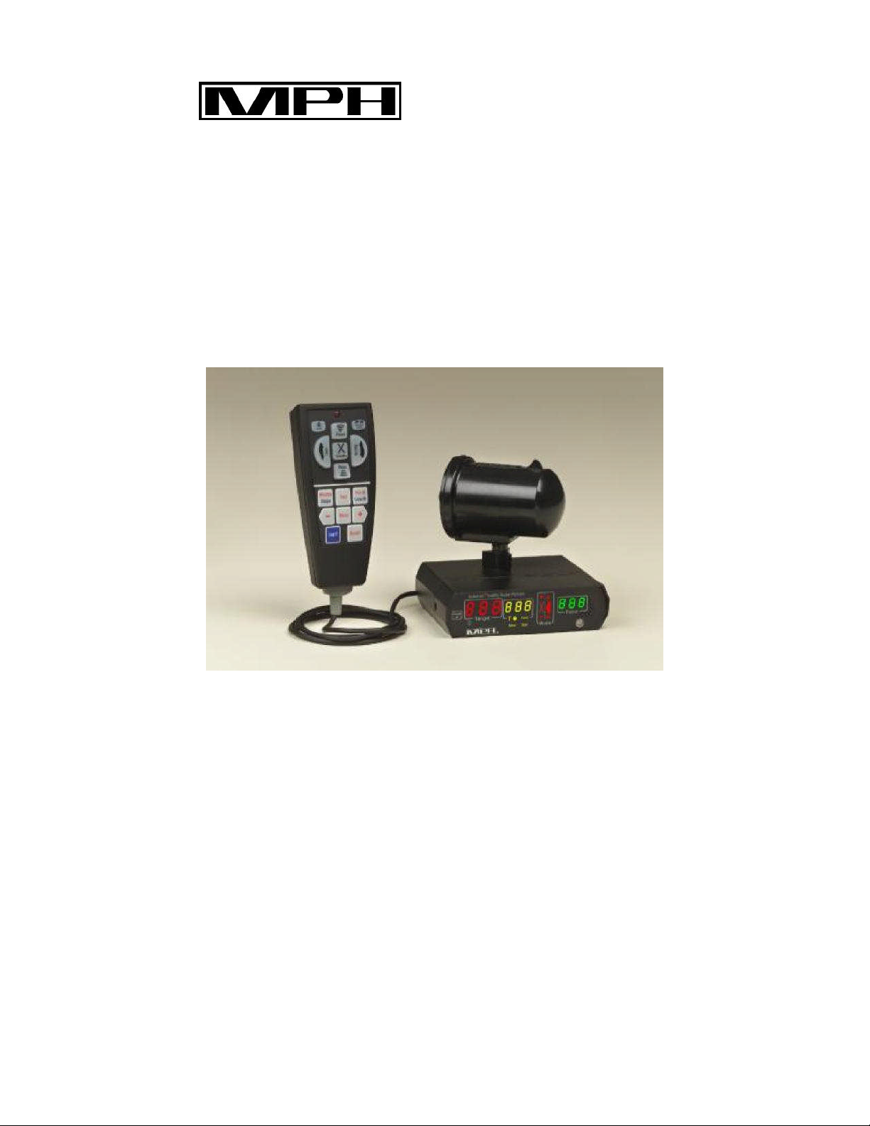
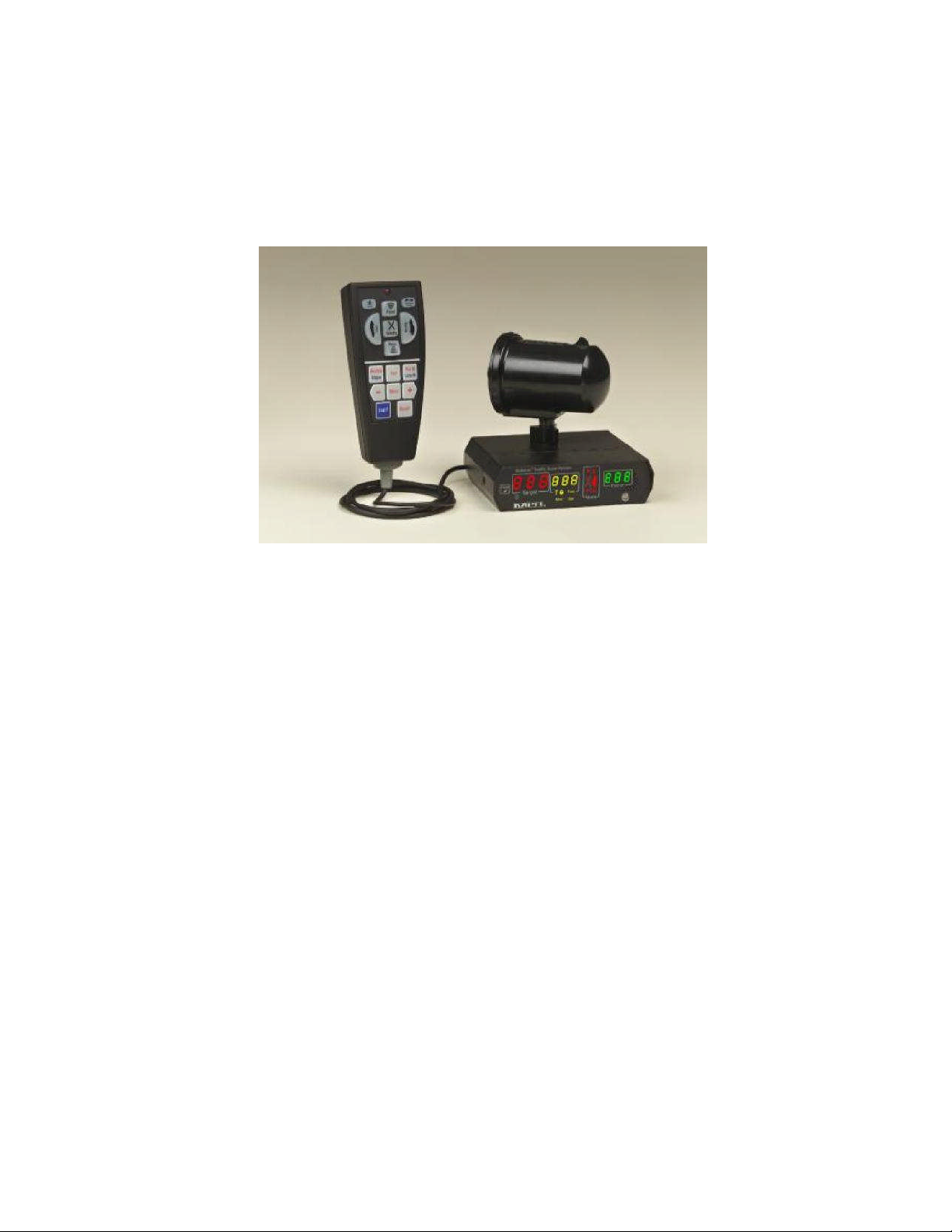
The MPH BEE III is comprised of one or two antennas, a wired remote control (wireless
optional) and a detachable display/counting unit. MPH designed the BEE III using only the
highest quality parts. Combined with the workmanship provided by MPH`s Manufacturing
Department, the BEE III will provide years of reliable performance.
The MPH BEE III offers more than features and performance. MPH provides training
through our network of experienced field representatives. We know that our success
depends upon your success with our equipment. We are dedicated to keeping our customers
satisfied. The following pages describe the operation of the MPH BEE III radar. We can
also provide useful information on the legal aspects of traffic radar at your request.
Installation
Range and Radar Placement
The range or targeting distance of the radar is influenced by how it’s mounted in the police
vehicle. Heater fans are moving targets and can be detected if energy from the antenna is
reflected toward the fan. The best solution to this problem is to find a location that
minimizes this effect. To determine this location, place the unit in stationary mode, turn the
volume up and open the squelch. This enables any target or interference to be heard. If
changing fan speeds alters the audio signal, the fan is being picked up in that mounting
position; try to find a different location. Dropping the fan speed may also assist. Reducing
the range setting of the radar is another option. If you have persistent problems with fan pick
up, call the factory for suggestions specific to your particular police vehicle.
Power Source
Cigarette lighter receptacles have been the traditional source of power for traffic radar.
However, poor grounding, electronic ignition bleed over, and alternator noise can combine
to create an unacceptably high level of ambient electronic interference. In some instances, an
unusually noisy vehicle ignition/alternator can result in spurious readings and/or reduce the
targeting range of the BEE III.
To combat this it’s recommended that a shielded cable be run directly from the battery to an
auxiliary receptacle within the police vehicle. This should effectively eliminate any power
source problems.
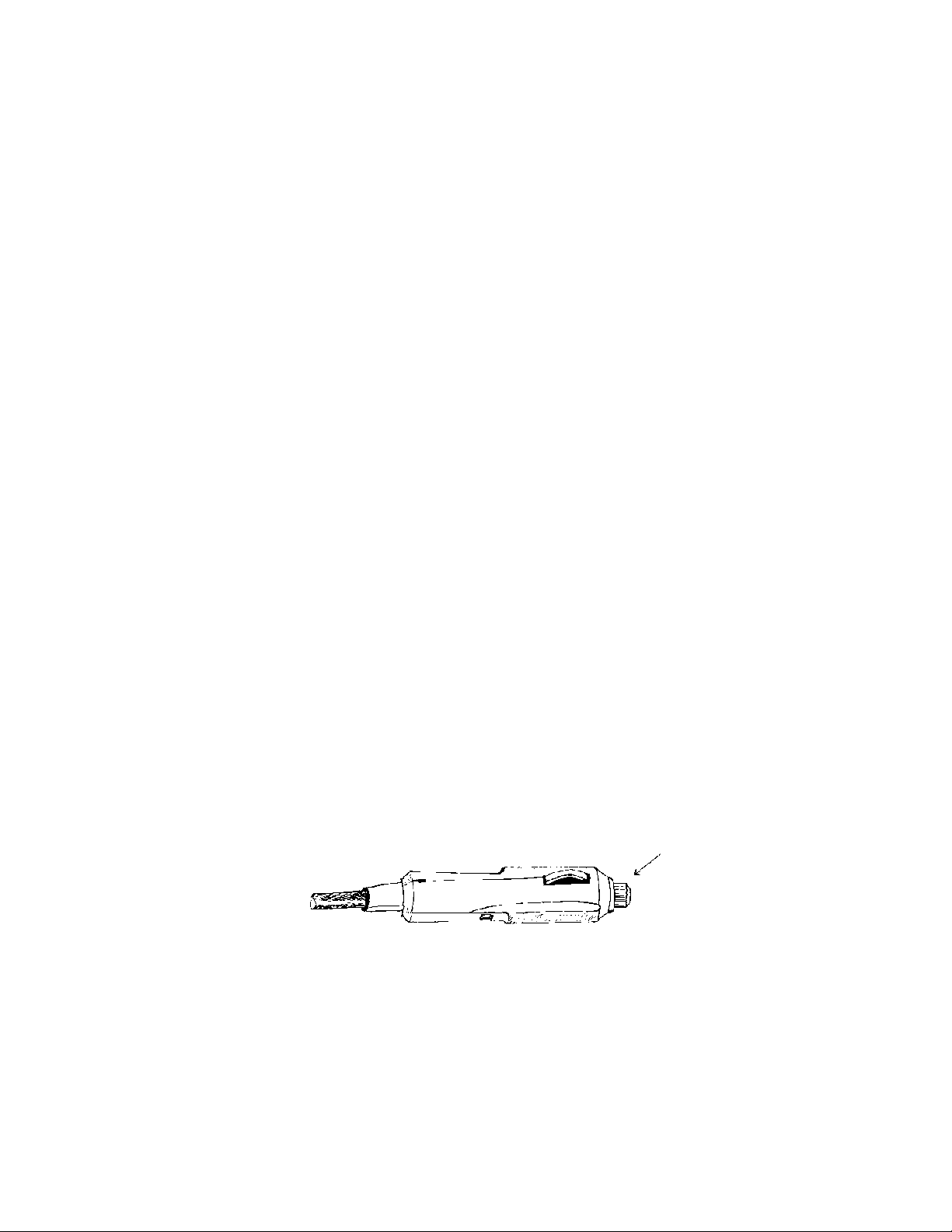
Fuse Replacement
BEE IIIs are shipped with a fused cigarette lighter plug. The fuse is housed inside the tip of
the plug. (See arrow in below illustration.) To remove fuse: unscrew and remove the tip and
the fuse. Replacement fuses should be commonly available 2 Amp, AGC type fuses. Higher
Amperage fuses are not recommended and may violate the manufacturer’s warranty.
5
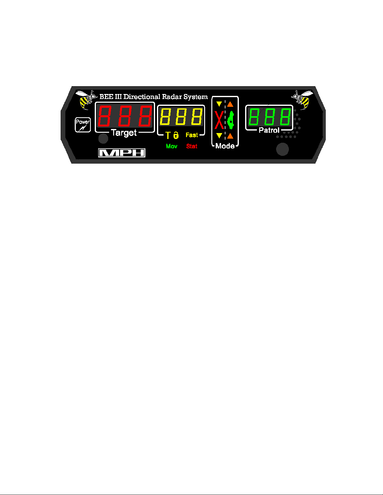
BEE III Display
The BEE III utilizes a high contrast LED display with automatic dimming.
Mode
The mode section is structured like a roadway and offers operators a pictorial view of the
radar’s functions. A large red “X” icon in the left lane informs operators that the
transmitter is in standby (off). A large green car in the right lane indicates that the
transmitter is active (on).
The operating mode of the BEE III is illustrated with the scene of a patrol car and selected
targets. In opposite direction moving mode, the scene shows an arrow in the left lane of
traffic; it is ahead of the patrol car if the front antenna had been selected and behind the
patrol car if the rear antenna was selected. In same direction moving mode, the arrows are
shown moving in the same direction as the patrol car. Moving mode is indicated by “Mov”
which appears below the middle speed display window.
In stationary mode, the mode window works similarly. Indicator arrows appear in front or
behind the patrol vehicle icon to indicate the selected antenna. In the opposite direction the
scene shows an arrow in the left lane of traffic. If the same lane of traffic is selected the
arrow in the right lane is lit. If both directions of traffic are selected, arrows in both lanes
will be illuminated. Stationary mode is indicated by “Sta” which appears below the middle
speed display window.
Speed windows
The BEE III has three windows for speed display. They are arranged by function and are
identified by the colors red, yellow and green.
The left most display is a dedicated red TARGET window. This window always displays the
strongest target’s speed, even in fastest mode. Radio frequency error conditions (rFi) are
displayed in this window.
6

The yellow middle window performs two functions; an icon located directly below the
7
window indicates each. If the window is being used to display a locked target speed, a
T-lock (T ) icon is lit. Only the speed of the strongest target can be locked. If the middle
window is being used to display the speed of the fastest vehicle (fastest mode), a FAST icon
is lit. General error conditions (Err) are also indicated in this window. When “rFi” is
indicated in the leftmost window, this window will display the relative strength of the signal
causing the interference.
The green window on the right side of the display shows the PATROL vehicle’s speed in
moving mode and remains blank in stationary mode. The speed displayed in this window
should correspond with the patrol vehicle’s speedometer. If a low voltage condition occurs,
“Lo” will appear in this window.
Doppler audio
The BEE III features a speaker on the front panel for Doppler audio. The BEE III's audio is
derived directly from the received Doppler signal (not synthesized) and is useful as an aid in
target identification. The loudness is proportional to the strength of the received signal and
increases as the target vehicle approaches. The pitch of the audio signal increases with
higher closing speeds. The Doppler audio always corresponds to the strongest target, even
when the radar is in fastest mode.
In stationary strongest mode (no specific direction selected) the Doppler audio heard is that
of targets traveling in both same and opposite directions. In directional stationary mode
(only same or opposite direction targets selected) the Doppler audio heard will be from the
selected direction only.
Display dimming and infrared remote sensor
A photocell located on the display panel automatically adjusts display brightness to ambient
light conditions. An infrared sensor also located on the display panel receives commands
from the optional wireless remote.
Power button
This button controls power for the BEE III radar. When the BEE III is turned off, the radar
retains all previous settings (volume, mode, etc.) with the exception of range, which defaults
to maximum. When the unit is next powered on, speed displays are blank and the unit starts
in standby mode.
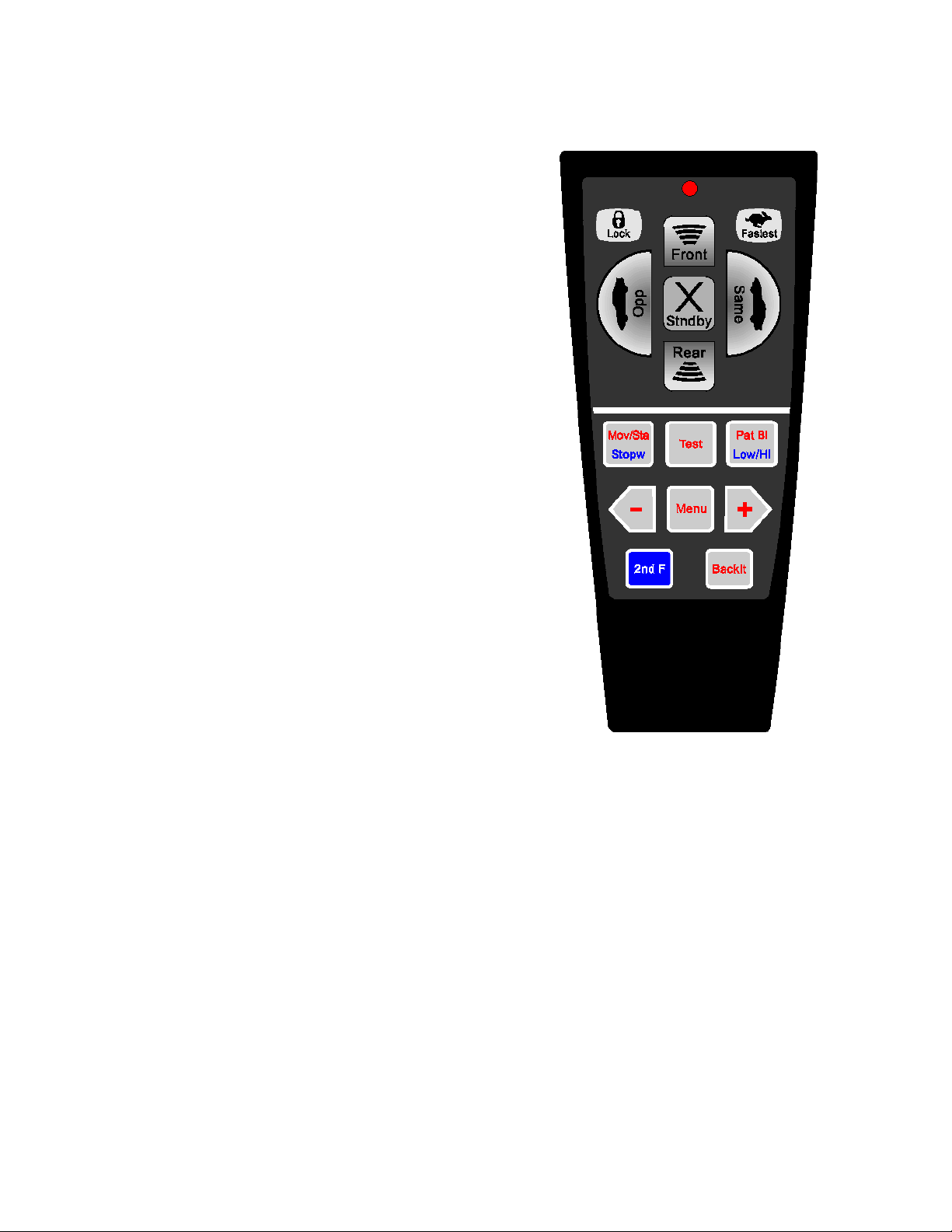
BEE III Remote Control
8
The BEE III remote has two main sections of
controls. An upper section with raised rubber
buttons and a lower section with flat membrane
buttons.
Operating mode keys (Upper section)
The most commonly used buttons are located at the
top of the remote. They are raised rubber and are
contoured so that the operator’s thumb is cradled in
the center of a five-button cluster. This design
facilitates easy control of the radar’s operating
modes while at the same time, allowing operators to
keep their eyes on the road. All keys are backlit for
night time use.
Front: Selects Front antenna.
Rear: Selects Rear antenna.
Stndby: Places radar into Standby (transmitter-off).
Opp: Places radar into Opposite direction mode.
Same: Places radar into Same direction mode.
Lock: Locks Target speed in lock window.
Fastest: Activates Fastest vehicle mode.

Other buttons (Lower section)
enter into POP mode. It also functions with the “Menu” button. If a menu
9
The lower section of the remote contains flat membrane-type buttons that are embossed
around their edges to make them easy to identify by feel.
Some buttons contain two text colours. The red text is the default function; pressing the
button by itself will cause it to perform that function. The function in blue text is initiated by
first pressing the blue “2
nd
F” button.
Mov/Sta: Toggles the radar between moving and stationary operating modes.
Stopw: Activates stopwatch mode (“2
nd
F” button must be pressed first).
Test: Manually initiates a radar self-test. The radar will momentarily illuminate all displays
and icons followed by simulated speeds. If no problems are detected it will return to the
previous mode of operation. If a problem is found the radar will display “Err” (error) and
cease the speed measurement process.
POP
Note: Never activate Test during target acquisition.
The radar also performs internal self-checks during normal operation (initiated
automatically). If operating correctly a double beep will be heard or alternatively,
“Err” (error) if a problem is found.
Pat Bl: When in Standby mode, pressing the “Pat Bl” button will clear the patrol speed
display. (“2
cause the locked patrol speed to reappear.
nd
F” button must be pressed first). Pressing “Pat Bl” a second time will
Low/Hi: Selects the City or Highway filter and determines the low end patrol speed. “Ci”
(City mode) or “Hi” (Highway mode) appears in the patrol window while in
Standby.
– Once pressed a “P” appears in the middle window. POP + must be selected to
POP
selection has been made it will decrease the setting.
Menu: Facilitates the selection of modes and settings that do not have individual buttons on
the remote. For further information see the Menu section of this manual.
– Direct entry into POP mode. It also functions with the “Menu” button. If a
menu selection has been made it will increase the setting.

2nd F: Selects the secondary “blue” function of a button instead of the red primary
10
function. “2nd” appears in the middle window when pressed. Pressing a second
time causes “2nd” to disappear and allows the radar to select the primary “red”
function.
Backlt: This button performs no function for wired remote controls.

Menu Options
11
One press of the “Menu” button – Adjust Audio Volume
Audio volume has 7 available settings (0 through 6, with 0 being “mute”). During volume
adjustment, “A” is displayed in the middle window of the radar followed by the current
setting.
MPH sets the initial level at 4. On subsequent power-ups the BEE III retains the last known
volume setting (when powered off).
Pressing the “—” button lowers the volume one level; pressing the “+” button raises the
volume one level. Pressing the “Menu” button after making an adjustment returns the radar to
its normal operating mode. Pressing the “Menu” button without making an adjustment causes
the radar to move to the next menu setting.
Note: Operators are required to utilize Doppler audio at all times to assist with both target
identification and tracking history.
Two presses of the “Menu” button – Adjust Squelch
The squelch has two settings: on and off. Squelch “on” causes the radar to produce an audio
tone only when a target is present, while Squelch “off” causes the Doppler return signal to be
amplified at all times. During squelch adjustment, “S” is displayed in the middle window of
the radar, followed by the current setting (“n” for on and “f” for off).
On its initial power-up the squelch is “on”. On subsequent power-ups the BEE III retains the
last known squelch setting (when powered off).
Pressing either the “—” button or the “+” button causes the radar to toggle between Squelch
“on” and Squelch “off”. Pressing the “Menu” button after making an adjustment returns the
radar to its normal operating mode. Pressing the “Menu” button without making an
adjustment causes the radar to move to the next menu setting.

Three presses of the “Menu” button –Adjust Dynamic Stationary Mode
12
In dynamic stationary mode, the radar automatically toggles itself between moving and
stationary mode dependant upon vehicular motion.
Dynamic stationary mode is automatically turned “on” if the radar detects a speedometer
interface during power-up. Operators are given the option to turn this feature “on” or “off”.
The setting is indicated on the radar menu by the letters “dS”. Dynamic stationary mode can
be turned “on” by pressing the “+” button (“dSn”) and can be turned “off” by pressing the “—
“ button (“dSf”). Dynamic stationary mode is available only if the vehicle speedometer
interface cable is connected to the BEE III radar.
Note: Earlier models do not contain this menu option.
Four presses of the “Menu” button – Adjust Range
The BEE III radar has 7 available range settings (1 through 7). Adjustment affects the radar’s
sensitivity and not the transmitted power. During range adjustment, “r” is displayed in the
middle window of the BEE III followed by the current setting.
Upon initial power-up the range defaults to maximum (7).
Pressing the “—” button decreases the range one level; pressing the “+” button increases the
range one level. Pressing the “Menu” button after making an adjustment returns the radar to
its normal operating mode. Pressing the “Menu” button without making an adjustment
causes the radar to move to the next menu setting.
Five presses of the “Menu” button – Enter POP mode
POP mode is initiated by pressing the “Menu” button five times, until a “P” appears in the
middle window. POP can also be turned on by pressing the “+” button and can be turned
off by pressing the “—“ button. Once activated the middle speed window will display
“POP”.
Note: A sixth press of the “Menu” button cycles back to audio volume adjustment.

BEE III Operational Modes
13
Practical use of the BEE III
The BEE III enables the operator to choose a variety of operational modes including
Stationary, Moving (opposite or same direction) and Pacing.
A. Stationary Radar
When operated in stationary mode (patrol vehicle stopped), the BEE III radar allows the
operator to monitor traffic driving towards or away. This type of operation is usually
carried out in areas of high-speed traffic or complaint. In stationary mode the patrol
window remains blank.
ASDTM technology enables the operator to monitor traffic travelling in the same
direction as the patrol vehicle, in the opposite direction or in both directions
simultaneously. This selection can be made from either the front or rear antenna. The
operator can also monitor the fastest target traveling in the selected direction in addition
to the strongest target.
B. Moving Radar (Opposite Direction)
The BEE III radar monitors the speed of both approaching and receding motor vehicles
and displays in the target window.
Patrol vehicle speed is continuously displayed so operators can compare it to the
speedometer reading. If these speeds correspond, the operator is assured that the target
reading is correct following the completion of a proper tracking history.
In opposite direction mode care should be taken by the operator to recognize that the
violator is traveling above the posted limit. Proper identification of the violating motor
vehicle must take place and at the time of speed determination, the patrol vehicle's
speed must correspond with the reading on the speedometer. If these steps are taken,
the operator is confident that the radar displayed a true and accurate target vehicle
speed.

C. Moving Radar (Same Direction)
14
Same direction mode enables the BEE III to track targets that are moving either faster or
slower than the patrol vehicle. This mode is best used in light traffic where visual target
identification is less difficult.
The BEE III incorporates an advanced, patented technology called Automatic Same
Direction
TM
(ASDTM) processing. This allows the BEE III to determine the absolute
speed of a same direction target without requiring operator input. In other words, same
direction operation is AUTOMATIC thus simplifying same direction operation.
Target vehicles traveling near or at the same speed as the patrol vehicle will not be
sensed by the BEE III as they generate a minimal to non existent Doppler shift.
While operating in same direction mode, an 8 kph differential (faster or slower) must
exist between the patrol and target before target readings are displayed. Operators must
keep this in mind because the closest motor vehicle may not be the target speed
displayed. In this mode only, target speed range is limited to ±70% of the patrol speed.
The range or sensitivity of the BEE III is greatly reduced in same direction mode. This
reduction eliminates more distant targets thus making target identification easier.
D. Pacing Radar
The BEE III provides the operator with an accurate means of pacing targets. In this
mode the radar essentially functions as a calibrated speedometer utilizing the patrol
display.

Advanced features of the BEE III
15
The following modes are very useful features assisting in target identification. Being
somewhat more complex, it’s recommended that operators become familiar with the more
conventional modes before operating these advanced features.
1. Fastest Mode
Fastest mode is available in all modes of operation. Pressing the “Fastest” button on the
remote control will initiate a search for any motor vehicle that is faster than the strongest
target. Activation of this mode will be indicated on the front panel, as the "FAST" icon
below the middle window will be illuminated.
The display's middle window will show the speed of the fastest target that’s moving
faster than the strongest vehicle, if such a target exists. Otherwise the window will be
blank showing that the radar is looking for a faster target but there isn't one within range
of the radar. The BEE III will remain in fastest mode until the fastest button is pressed
again or until a target speed is locked. Once pressed the radar will return to normal
(strongest target) radar mode.
The middle speed window will display the speed of the fastest target, while the normal
target window continues to display the strongest target. If the strongest target is the
fastest target within the range of the BEE III, the fastest window will be filled with
underscores. The Doppler audio and the mode window will continue to track the
strongest target when the radar is in fastest mode.
Locking a target while the BEE III is in fastest mode will lock the strongest target. The
BEE III will not allow speeds displayed in the fastest window to be locked.
In stationary mode, the radar only looks for faster targets in the selected direction, either
Same or Opposite. If the radar is being operated in both-direction stationary mode, the
radar only looks for faster targets moving the same direction as the strongest target is
travelling. It therefore may not show the speed of the absolute fastest target in this case. If
you observe a faster target that you want to observe, it is recommended that you place the
radar in directional stationary mode and select the direction in which that particular motor
vehicle is travelling. Page 19 should be referenced for more information.

2. POP
16
TM
Mode
This exclusive MPH feature, utilizes the latest in technology to thwart the efforts of
speeders who have purchased illegal speed measuring warning devices. Using the POP
mode, an operator can perform quick, accurate speed checks without alerting
approaching motor vehicles. Once a speeding vehicle has been detected, operators can
then switch to conventional mode, locking in the target while conducting a proper
tracking history.
With conventional radar, activating the front or rear antenna activates the transmitter.
Under ideal conditions speed readings can be obtained in approximately 1/2 second.
Most warning devices today can easily recognize this, alerting all so equipped motor
vehicles within several kilometers.
POP mode is initiated by either pressing the “POP +” button or by pressing the “Menu”
button five times. The operator must then press the “+” button to turn the mode on. The
middle speed window will display “POP”.
Once POP mode has been initiated, a momentary press of the “Front” or “Rear” antenna
button will activate the transmitter for a brief instant, long enough to acquire a target.
This pulse or burst of microwave energy is so short it’s undetectable by most speed
measuring warning devices. If the displayed speed is of interest, the operator simply
presses the corresponding antenna button once more and the radar will commence
conventional operation. “POP” will disappear from the middle speed window. If the
antenna button is not pressed again, the transmission is limited to the single pulse and
the BEE III remains in POP mode awaiting the next target.
To lock in a speed, the radar must be in conventional or continuous transmit mode. POP
mode readings produce a reference speed only and should not be utilized for
enforcement purposes (no Doppler audio). Speeds displayed as a result of POP pulses
cannot be locked. This has been implemented to ensure BEE III operators conduct a
proper tracking history prior to locking in a speed reading.
POP mode can be exited in several ways. One such method is to place the radar into
continuous transmit mode as described above. Another technique is by pressing the
“Menu” or “Standby” buttons on the remote. When you exit Pop mode, “POP”
disappears from the middle window.
Effective use of POP mode
Speed measuring warning devices are most effective on long stretches of roadway with
minimal traffic. In this situation, each time the speed is measured on a passing car all
motor vehicles with detectors are alerted. This is a perfect application for POP mode.
POP mode is best utilized at shorter ranges with some separation between targets.

Degree of effectiveness
17
When using POP mode most radar detectors will detect nothing even at point blank
range. A small percentage will detect it when pulses are repeated quickly (less than a
few seconds between pulses). An even smaller percentage will give a minor alert,
similar to what door openers and other interference sources cause. POP mode is
invisible in most cases, but always substantially less detectable than conventional radar
mode.
When possible it’s recommended operator’s sample a variety of speed measuring
warning devices to sample POP mode’s effectiveness.
A note of caution:
Offence notices should not be issued based solely on information derived from a single
POP burst as no tracking history has been developed. The radar should be placed into
continuous transmit mode by pressing the corresponding antenna button while the POP
speed is still displayed. Operators must conduct a proper tracking history.
3. Stopwatch Mode
Stopwatch mode makes use of precision counters from within the BEE III unit to
measure motor vehicle speed without microwave transmission. This function allows an
operator to measure the amount of time it takes a motor vehicle to travel a known
distance and then performs a speed calculation utilizing the following formula:
Speed = (distance traveled) ÷ (time required to travel that distance)
To enter stopwatch mode, operators must press the blue “2
nd
F” button on the remote
control followed by the “Stopw” button. “.0” will be present in the Target window and a
number in the Patrol window. The Target window is the time window and the Patrol
window shows the distance that the measurement will be performed over in meters.
To utilize this mode, operators must locate an area over which they wish to monitor
speed. This area will require two distinct points of reference or landmarks, both clearly
visible from the patrol car so that the timer can be accurately started and stopped. An
accurate distance between the landmarks is essential.
To achieve the best accuracy in stopwatch mode, the measurement time for a motor
vehicle to traverse the distance selected should be at least 10 seconds. To accomplish
this, landmarks in the city should be at least 100 meters apart increasing to several
hundred meters in the country.

Operators must next enter into the radar how far apart the landmarks are. Stopwatch
18
mode defaults to a distance of 100 meters. Each press of the “+” button will increase the
distance by 1 meter and each press of the “—” button will decrease the distance by 1
meter. Similarly each press of the “Same” button increases the distance by 10 meters
and each press of the “Opposite” button decreases the distance by 10 meters. Finally,
each press of the “Front” button increases the distance by 100 meters, while each press
of the “Rear” button decreases the distance by 100 meters.
The internal timer is started and stopped by pressing the “Lock” button. To measure a
motor vehicle’s speed, operators must press the “Lock” button when the target vehicle
passes the first landmark. When it has reached the second landmark, the “Lock” button
must be pressed again. This causes the timer in the Target window to freeze with the
calculated speed displayed in the middle window. Since this is a locked target speed, the
T-lock indicator will be illuminated under the middle speed window.
To measure the next motor vehicle press the “Lock” button again. This clears the
previous speed and resets the time to zero. To exit stopwatch mode, press the “Menu” or
“Mov/Sta” button.

Operational Concerns
19
Fastest Mode
Historically traffic radar displayed the strongest reflecting target. Case law has centered on
the ability of the radar operator to confidently identify whose motor vehicle is associated
with that particular speed. Due to technical limitations, it was relatively simple for analog
radars to process this method.
Advancements in technology have enabled modern DSP radars, such as the BEE III, to
process multiply targets simultaneously. Unfortunately no practical method exists to
communicate such information to an operator like air traffic control radar does.
Fastest mode gives the operator an opportunity to view one other target in addition to the
strongest. In this mode, the BEE III considers all possible targets within range (there may be
several) and display the absolute fastest.
While speed readings displayed in fastest mode are as accurate as those displayed in the
target window, visual identification of the offending vehicle can be more difficult. Fastest
mode is intended to be utilized as a method of gathering additional information about a
specific scenario.
Operation in fastest mode
Important points to remember when using the fastest mode:
1. In any mode, the BEE III’s target window always displays the strongest target in the
selected direction of travel. The speed displayed in the target window is the only speed
that may be locked.
2. If the strongest target is the fastest target, the speed will not be duplicated in the fastest
window. This serves as an alert to the operator that the strongest is the fastest, and its
speed may be locked. Often a speed will appear in the fastest window first and then shift
to the target window when the previous strongest target exits the radar beam. In these
situations, the fastest mode provides more tracking information and additional time to
observe or lock the target.
3. In some scenarios, such as a car passing a large truck, the fastest target, the car, will
never be the strongest reflection.

4. While visual identification of the strongest target is straight forward, identification of the
20
fastest target requires more operator attention. In the above scenario when a car passes a
large truck, the fastest window may display the speed of the car or alternatively, that of a
faster motor vehicle within range of the radar. When in fastest mode operators must be
aware of all potential targets. BEE III operators can never assume that the fastest target
is the second strongest reflector.
5. In fastest mode the BEE III’s range setting defaults to maximum. Changing the range or
sensitivity will have no effect on fastest targets.
Moving Same Direction Mode
The BEE III allows the tracking of targets moving in the same direction as the patrol vehicle.
This mode can be slightly more difficult to operate especially in heavy traffic where visual
target identification is not as easy.
Operation of moving same direction mode
Same direction moving mode is selected by pressing the “Same” button on the remote
control when the radar is in moving mode.
The BEE III’s ASDTM technology allows it to determine the difference between a target
traveling faster or slower than the patrol vehicle.
With ASDTM, a target travelling 10 kph slower than the patrol vehicle and a target travelling
10 kph faster than the patrol vehicle do not produce the same signal at the radar antenna. It is
true that the Doppler tone generated in the speaker by each target corresponds to 10 kph.
However the signals present within the antenna are different.
When operating the front antenna, a target moving slower than the patrol vehicle is actually
getting nearer the patrol vehicle and produces a return signal that is at a higher frequency
than the transmitted signal. Conversely a target moving faster than the patrol vehicle is
moving away from the patrol vehicle and produces a return signal that is at a lower
frequency than the transmitted signal. When operating the rear antenna, the radar functions
in a similar manner.
ASDTM technology can tell the difference between these two frequencies (whether it’s
higher or lower than the transmitted signal). The BEE III automatically determines if the
target is approaching or receding and calculates the proper target speed.

Important points to remember when using the same direction mode:
21
1. Targets traveling at or very close to the patrol speed are considered invalid by the BEE
III. Thus a target may be directly in front of the patrol car, but if it’s travelling at a
similar speed (within ±7 kph of the patrol speed) it will not be a read as a target. In same
direction mode, the target window displays the strongest motor vehicle that is travelling
at least ±8 kph outside of the patrol speed.
2. Range or sensitivity is fixed in same direction mode and is reduced substantially from
opposite direction mode. The range adjustment controls still function however any
change will only affect the opposite and stationary modes.
3. Heater / air conditioner fan interference can be a problem in same direction moving,
especially when the speed displayed varies with the patrol. Physical placement of the
BEE III antenna can assist.
4. In same direction mode operators must complete a speed discrimination test to ensure
target validity. When the patrol speed changes, the target should remain constant. If the
target speed tracks your patrol speed (increases as you accelerate or decreases as you
decelerate) the reading is invalid and was a result of fan interference.

BEE III Testing Procedure
22
Tests are to be conducted by operators at the beginning and end of shift and/or
enforcement.
Power up
When the BEE III radar is first powered on it initiates a complete self test. First a light test is
performed, in which all display segments / indicators will light, followed by the current
software revision. This is followed by an internal circuitry test of 32 kph in both the target
and patrol windows. After the internal circuitry test, PAS is displayed followed by the
current antenna configuration. A3 for Ka band, A2 for K band, and A0 if no antenna is
connected.
Manual self test of the radar
Press the “Test” Button located on the remote control. The radar will then perform an
internal test of the processing circuitry. First the radar will light up all of its display elements
in a segment test. Next the radar will tell you the software revision, for example “bEE III
022” for BEE III revision 2.2. And finally the radar will test itself with two Doppler tones,
first in stationary mode at 32 kph and then at 32/32 in moving mode. You will also hear the
Doppler audio associated with these test speeds. If all of the checks are successful, the radar
will respond with PAS and a double “test OK” beep. Otherwise the radar will indicate a
“fail” condition by displaying “Err”.
Immediately after passing the internal test, the letter “F” will be displayed in the target
window for approximately 30 seconds. This “F” indicates that the radar is in tuning fork test
mode, a test lab requirement of the International Association of Chiefs of Police (IACP).
Tuning fork tests are not required in some Canadian provinces however operators must
comply with provincial policy and/or guidelines. . Operators are reminded that speed
readings should not be taken while the “F” is present.
The BEE III periodically tests itself while the radar is operating. If no errors are detected,
the radar will give indication of this with a “test OK” double beep. If an error is detected,
the BEE III will indicate this by displaying “Err” and ceasing to display target speeds. In the
event of a test failure, the radar must be removed from service until the problem is resolved.
The BEE III will not process speeds when an error condition is present.
Road test
When the radar is operated in moving mode, the patrol speed indicated in the patrol
window must match the speed of the speedometer within +/- 3 kph. If this is not the case,
please check the radar antenna(s) for proper alignment with the roadway. In the event of a
test related failure, the radar must be removed from service until the problem can be
resolved.

Interference Information and Precautions
23
There are several factors that can influence the operational behavior of Doppler radar. These
influences can be natural or man-made. A knowledgeable operator will not be confused by
these external influences.
1. Natural Influences
Driving rain, heavy snow, or blowing dust can cause a scattering effect thus decreasing
the effective targeting range. Inclement weather or slick road surfaces may also affect
the patrol display. A patrol speed comparison with the speedometer is required.
Terrain can affect the targeting range. Should the patrol car be on a slight decline, the
antenna could be shooting short of the target vehicle. If on a slight incline, it could be
shooting over the target vehicle. Range may be shortened in either case.
Strong reflectors can create target readings that are the same as the patrol speed when in
moving mode. To avoid this problem the BEE III detects such harmonics and inhibits
target speed display.
In moving mode the BEE III derives its patrol speed primarily from the road’s surface
(strongest reflection). However under some situations, excessively large signals can be
received from other objects such as guardrails or large signs. This can sometimes create
a harmonic frequency of twice the patrol speed to appear. Harmonic detection software
inside the BEE III senses this condition and inhibits target speed display.
Note: The harmonic detection feature may cause occasional blanking of legitimate target
speeds when equal to the patrol speed, or a multiple of it. If the operator suspects this is
the case, change your speed. If the closest target is blanked due to the harmonic detector,
the BEE III will not display a weaker more distant target in its place.
2. Man-made Influences
Such influences are normally the most troublesome because they generally involve
electronic signals that may cause spurious displays, or lessen the effective range. Power
transformers, radio transmitters, neon lights, etc. generate electronic noise. These
influences create a phenomenon that can cause radar to display spurious readings or
lessen the effective range. The Radio Frequency Indicator (RFI) will indicate the
presence of strong RFI fields created by local transmitters. To eliminate RFI induced
readings, target speeds are inhibited when this indicator is on. Intermittent signals may
also be caused by electrical noise produced by the vehicle’s alternator or ignition
system. The RFI detection circuitry will recognize this noise and suppress speed
readings. Operators must be aware that these sources of electrical noise exist and that
they may affect radar operation.

Intermittent readings need not be confusing if the officer is familiar with the operation
24
of the BEE III. For example, if the radar is directly pointed at the dashboard of the patrol
vehicle, the rotation of the defroster/heater fan may be detected. The BEE III comes
equipped with specially designed mounting brackets that assist in shielding such
interference sources, helping to eliminate intermittent readings. Reading the fan speed is
annoying and in some cases, can reduce the effective range of the speed measurement
device.
MPH Industries suggests the following if fan interference is suspected:
1. Determine if the fan is the source of interference by checking whether the readings
are eliminated when the fan is turned off or if they change when the fan speed is
adjusted.
2. Reduce the effects of the fan by locating the BEE III antenna in an area that is less
susceptible to the fan motion. MPH Industries provides several mounting options. In
some cases the left-hand corner of the dash has been found to be the best location.
Alternately the antenna may be mounted outside of the patrol vehicle.

Getting Started - An introduction to the BEE III
25
This step-by-step guide will help you get started using the BEE III and show you how to
operate its different modes. Working through this tutorial will take less than an hour, and it
will teach you everything that is necessary to take full advantage of the BEE III's capabilities.
This guide is not intended to replace the BEE III’s normal testing procedure.
We encourage our customer’s to copy these pages and use them as a checklist for training.
Checkboxes are provided to keep track of your progress.
Turn the BEE III on.
Press and release the “Power” button on the readout to turn on the Bee III. When first
turned on, the BEE III will power up in standby mode with the range set to maximum.
After initial power up the unit will return to the mode in which it was turned off.
Perform a self-test.
Press the “Test” button, located approximately in the middle of the remote control. This
causes the radar to perform an internal test of the processing circuitry. First the radar
will light up all of its display elements in a segment test. Next the radar will tell you the
software revision, for example “bEE III 022” for BEE III revision 2.2. Finally the radar
will test itself with two Doppler tones, first in stationary mode at 32 kph and then at
32/32 in moving mode. You will also hear the Doppler audio associated with these test
speeds. If all of the checks are successful, the radar will respond with a double “test OK”
beep. Otherwise the radar will indicate a “fail” condition by displaying “Err”.
Immediately after passing the internal test, the letter “F” will be displayed in the target
window for approximately 30 seconds. This “F” indicates that the radar is in tuning fork
test mode, a test lab requirement of the International Association of Chiefs of Police
(IACP). Tuning fork tests are not required in some Canadian provinces, as is the case
with some US jurisdictions. See page 22 for full testing details.
The BEE III periodically tests itself while in operation. If an error is detected it will
indicate this by displaying “Err” and ceasing to display target speeds. If errors are not
detected, the radar will give indication of this with a “test OK” double beep. In the
event of a test related failure, the radar must be removed from service until the
problem can be resolved. The BEE III will not process speeds while an error
condition is present.

Select the operating mode.
Now press the “Same” button on the remote. The illuminated arrow
26
Look at the radar’s remote control. You will notice a cluster of raised
rubber buttons on the top portion of the remote. Two of these buttons,
the half-moon shaped ones, are used to select the operating mode. The
left button selects opposite direction while the right button selects same
direction. Press “Opp”.
Now press the “Mov/Sta” button. The radar will enter moving mode.
You can tell this because the “Mov” icon is lit below the middle
window. In stationary mode, the “Sta” indicator would be illuminated.
Press the “Front” button. The front antenna will now transmit if one is
connected to the radar. Notice that the radar responds to all commands
with a beep, letting you know that the BEE III understood and executed
the action.
The selected mode will be illustrated in the MODE window, which is located on the
BEE III's front panel. The green car is lit (meaning that you are not in Standby), and
since you are in opposite direction moving mode on the front antenna, the arrow in the
opposite lane of traffic ahead of the patrol car is on. In all cases, the arrows indicate the
traffic direction that’s being monitored.
Now, press the “Standby” (Stndby) button on the remote. Notice that the red X is
illuminated, indicating that the unit is in standby. None of the arrows are on since traffic
is not being monitored.
Now press the “Rear” button on the remote (if the radar is equipped with a rear
antenna). The arrow that is behind the patrol car in the opposite lane of traffic is lit,
since the radar is in opposite direction moving mode and transmitting on the rear
antenna.
moves from the opposite lane of traffic to the same direction traffic,
directly behind the patrol vehicle.
Press the “Front” button. The illuminated arrow moves to the front of the
green patrol car since same direction traffic in front of the patrol vehicle
is being monitored.
You will notice a “Slower” or “Faster” button does not exist like on older same
direction radars. This is because the BEE III has Automatic Same DirectionTM
technology, a patented technology that allows it to process same direction targets

automatically, so you don’t have to press a button to tell the radar whether the target
27
vehicle is moving faster or slower than your patrol vehicle.
Try out stationary mode.
Press the “Mov/Sta” button. The radar will enter stationary mode. You can tell this
because the “Sta” icon is lit below the middle window and the Patrol window is filled
with dashes. In moving mode, the “Mov” indicator would be illuminated.
In stationary mode, you can select the target direction you wish to monitor. When
stationary mode is first initiated, operators will notice both arrows illuminated (mode
window) in the direction of the antenna you’ve selected. Similar to conventional radar,
this indicates that the BEE III will measure the speed of a target travelling in both
directions. As soon as the target’s speed has been displayed, the radar will indicate in the
mode window the direction of travel. This unique feature helps an operator positively
identify which target is being measured.
Now, press the “Same” button on the remote. You will notice that only the arrow
corresponding to the patrol car’s lane is illuminated. This indicates that the radar will
only measure the speed of motor vehicles travelling in that direction (moving away from
the patrol vehicle on the front antenna and approaching the patrol vehicle on the rear
antenna). The radar will only measure the speeds of vehicles moving in the same
direction as the patrol car, regardless of whether there’s a stronger target moving in the
opposite direction. The BEE III ‘s directional capability enables the radar to discriminate
based upon direction allowing operator’s to focus on specific traffic.
Now press the “Opposite” (Opp) button on the remote. You will notice that the arrow
moves over to the other lane of traffic in the Mode window. In this mode, the radar will
only display the speed of motor vehicles moving in that direction (moving toward the
patrol vehicle on the front antenna and away from the patrol vehicle on the rear
antenna). Like in the previous example, the radar will only measure the speed of motor
vehicles moving in that direction.
Operators can toggle between the direction you want to monitor by pressing the “Same”
and “Opp” buttons. If you wish to go back to monitoring both directions simultaneously,
press the “Mov/Sta” button twice.
Try locking in a speed.
This is a good time to try the lock function. While the readout is displaying a speed in
the Target window, press the remote’s “Lock” button. Note that the target speed is
locked in the middle window. Also the T-lock icon (T ), which is located directly under
the BEE III's middle window is illuminated, designating that the speed in the middle
window is a locked target speed.

Every time the “Lock” button is pressed, the radar will transfer the speed in the Target
28
window over to the middle window. Also if you place the radar into Standby, the
operating mode at the time the speed was locked will be displayed in the Mode window.
To clear a locked speed, press either the “Front” or “Rear” antenna button once. This
will clear the locked speed regardless of whether or not there’s a target speed currently
displayed in the Target window.
Locked speeds can also be erased in other ways. If the radar is placed into Standby, the
locked speed is preserved, but if the BEE III is then made to transmit again, the locked
speed is cleared (IACP requirement). Also locked speeds are automatically cleared 15
minutes after locked to preserve evidence integrity. The automatic clearing is preceded
by a 30 second countdown if the BEE III is in Standby to inform the officer.
A double click of the “Lock” button will also clear the lock window.
Try the menu system.
Press and release the “Menu” button on the remote control. The middle speed window
of the readout will indicate “A— ”. You can adjust the Audio volume with the “+” and
“—” buttons while “A— ” is displayed, where the “—” will be the current volume
setting.
Press and release the “Menu” button twice on the remote control. The middle speed
window of the readout will indicate “S n”. This indicates that the Squelch is “on” and
Doppler audio is only present when a target speed is being displayed.
Now, do not push any buttons for 5 seconds. You will notice that the “S n” in the middle
window disappears. In all cases, after the menu buttons have not been pressed for 10
seconds the Bee III will revert back to its normal operating mode.
Press the “Menu” button twice again. While the “S n” is being displayed, press the “—”
button on the remote. The middle speed will now read “S f”, indicating that the Squelch
is now turned “off” and that the Doppler audio will be amplified at all times, even when
no target is present. As you have noticed, the “—” button also acts as an “off” button for
the menu. You can turn the Squelch “on” by pressing the “+” button while the “S” is
present in the middle window or turn it “off” by pressing the “—”button.
Press and release the “Menu” button three times on the remote control for Dynamic
Stationary. The middle window will display “dSn” if a speedometer interface is
detected. If not detected the middle window will indicate “dSf”. Please note earlier
models do not contain this menu option.

Wait until the middle window clears again and then press the “Menu” button four times.
29
The middle window will display “r __”, where the “—” is the current Range setting.
Pressing the “—“button will decrease the Range setting by one each time the button is
pressed. To increase the Range setting, press the plus “+” button.
If you press the “Menu” button five times, you’ll notice that the radar will display a “P”
in the middle window. This initiates the POP
TM
mode, which will be discussed in the
section on advanced features of the Bee III.
Place the radar back into standby. You’ll notice the word “Ci” or “Hi in the Patrol
window. This indicates whether the radar is in City or Highway mode. City mode should
be used for low patrol speeds as it reduces combining. Highway mode should be used
for higher patrol speeds, say over 65 kph, to resist shadowing.
Take a look at the remote control. One of the buttons is marked “Pat Bl” in blue and
“Low/Hi” in red. When the button is pressed by itself, it allows operators to toggle the
radar between City (Low) and Highway (Hi) modes using the “+” and “—” buttons.
Use the fastest button.
The button with the rabbit icon ( ) on the remote control activates the fastest target mode
while the BEE III is transmitting. Fastest mode is available in stationary and same /
opposite direction moving mode. The use of this feature will be described later.
Find some real targets using stationary mode.
Place the BEE III into stationary mode. With a target present, press the “Front” antenna
button. The BEE III will beep and turn the front antenna on. A speed will be displayed
in the TARGET window.
If you wish to lock in the speed, press the “Lock” button. The target speed will move to
the middle display window, and the “T lock” (T ) icon below that window will be
illuminated. After locking a target, the BEE III will continue to track it until the radar is
placed into Standby. The target may be re-locked at any time by pressing the “Lock”
button again.
Now place the radar into Standby (“Stndby” button). Notice that the locked speed is
preserved in the middle window. It will be erased if the radar is placed back into
transmit mode. It will also be automatically erased 15 minutes after it is locked if the
radar is not placed back into transmit mode.

Find some real targets using moving mode - opposite direction.
30
Place the BEE III into moving opposite mode. While driving, once an approaching
target is present and within visual range, press the “Front” antenna button. Both your
patrol and target speed should be displayed.
Similar to stationary and moving same direction, if you wish to lock in the target speed,
press the “Lock” button. The target speed will move to the middle display window, and
the “T lock” (T ) icon below that window will be illuminated. After locking a target, the
BEE III will continue to track it until the radar is placed into Standby. The target may be
re-locked at any time by pressing the “Lock” button again.
Locking a target speed does not lock the patrol window until the unit is placed into
Standby. Keeping the patrol window active enables the operator to both verify the patrol
speed and establish the target’s tracking history.
The patrol blanking function is activated by pressing the “Pat Bl” button on the remote
control. It works when the unit is in standby with a locked target. Pressing the “Pat Bl”
button alternately blanks and unblanks the locked patrol speed in the patrol window.
Find some real targets using moving mode - same direction.
Place the BEE III into moving same direction mode. While driving, once a same
direction target is present and within radar range, press either the “Front” or “Rear”
antenna button. Both your patrol and target speed should be displayed.
Similar to both stationary and moving opposite direction, if you wish to lock in the
target speed, press the “Lock” button. The target speed will move to the middle display
window, and the “T lock” (T ) icon below that window will be illuminated. After
locking a target, the BEE III will continue to track it until the radar is placed into
Standby. The target may be re-locked at any time by pressing the “Lock” button again.
Locking a target speed does not lock the patrol window until the unit is placed into
Standby. Keeping the patrol window active enables the operator to both verify the patrol
speed and establish the target’s tracking history.
The patrol blanking function is activated by pressing the “Pat Bl” button on the remote
control. It works when the unit is in standby with a locked target. Pressing the “Pat Bl”
button alternately blanks and unblanks the locked patrol speed in the patrol window.

BEE III Accessories
Certification Services
The BEE III is provided with a certificate of calibration for the radar. The BEE III should be
periodically recertified per your provincial or departmental guidelines. The MPH Service
department offers a certification service for all MPH products. Contact the Service department
at (888) 689-9222 for more information.
Replacement or Additional Remote Controls
Remote controls function with any BEE III radar. Because the radar cannot be used without a
remote, it may be desirable to order a few spares especially if the BEE III will be shared
between patrol vehicles or operated on a motorcycle.
Mounting Brackets
A variety of mounting brackets is available for the BEE III. These include brackets for most
models of law enforcement vehicles and brackets for mounting the BEE III on motorcycles.
Service Manual
Copies of the comprehensive service manual for the BEE III may be ordered from MPH by
authorized service centers and select law enforcement agencies. Service manuals are not made
available for sale to the general public.
Operation Manual
A copy of this BEE III operation manual is provided with each BEE III purchased. Owners of
the BEE III, law enforcement agencies, and their affiliates can order additional copies of the
operation manual from MPH. As a rule, operation manuals in there entirety are not made
available to the courts or to members of the general public.
Speedometer Interface
The speedometer interface eliminates both shadowing and combining by comparing the
radar’s patrol speed to the speedometer. The module is connected to the vehicle’s VSS
(Vehicle Speed Sensor) line. Please contact MPH for the proper connection to your particular
vehicle.
Motorcycle Model
A version of the BEE III is available that is tailored for motorcycle usage. It includes a
waterproof display, wired remote control and standard waterproof antennas. The wired remote
control is designed to provide ease of operation attaching directly to the handlebar. A variety of
mounting brackets are available from MPH to facilitate safe and effective operation.
31

Quality Control Procedures
32
All BEE III traffic radars comply with the following quality control conditions:
o All parts and components are ordered to commercial high reliability, accuracy, and
performance specifications.
o Only vendors that meet MPH’s standards for quality are selected to supply parts and
materials.
o All electrical and electronic components are utilized within their performance
specifications, and adequate safety factors measures are provided for voltage, current,
and heat dissipation.
o Assembled circuit boards are individually tested before incorporation into higher level
assemblies.
o Each traffic radar is tested in an anechoic chamber for proper performance and
compliance to accuracy requirements.
o Each radar is tested (“burned-in”) for not less than twelve hours. After completion of
burn-in testing, the unit is again tested in the anechoic chamber to assure product
excellence.
o Samples of police traffic radars on the Conforming Product List (CPL) are tested by
outside laboratories for compliance to the requirements specified for Critical
Performance Testing (CPT) by the International Association of Chiefs of Police
(IACP).

BEE III Servicing
Product repair - During warranty period
All warranty repair of the BEE III will be performed by MPH's service center unless written
permission has been granted otherwise by MPH. Contact the factory for authorization and
shipping instructions to return any product considered to be covered by the manufacturer's
warranty.
Product repair - Outside warranty period
MPH suggests that the repair of BEE III radars outside of the warranty period be performed
by either their authorized Canadian repair facility or MPH's service center because of its
expertise in handling Doppler radar problems. All factory repairs are guaranteed by MPH as
detailed in the BEE III warranty. Consult the factory for repair procedures and charges.
The user is particularly advised to return the BEE III to MPH for repair whenever an
antenna problem is indicated. A large portion of the expense of the BEE III is contained in
the antenna assembly. Also, the microwave frequencies used by the antenna require the use
of specialized test equipment that is not available to the typical technician. Furthermore,
federal law dictates that any adjustments to the transmitter are made under the supervision
of a FCC-licensed technician. MPH has more than twenty-five years of experience servicing
Doppler radar antennas.
Statement of product warranty
MPH Industries, Inc. warrants that the BEE III will be free from defects in material and
workmanship, under normal use and service, for a period of two years from the date of
invoice to the original purchaser. Extensions of this product warranty may be purchased
from MPH. MPH's obligation is limited to repairing or replacing, as MPH may elect, any
part or parts of the BEE III that MPH determines to be defective in material or
workmanship. Warranty repair will only be performed at MPH's service center.
BEE IIIs considered to be covered by the conditions of this warranty shall be returned,
freight pre-paid, to MPH. The repaired or replaced product will be returned from MPH prepaid.
Warranty coverage extends only to the original purchaser and does not include normal wear
and tear, unusual abuse, or the use of the product for other than its intended purpose. This
warranty is void if the BEE III is adversely affected by attaching any feature or device to it,
or is in any way tampered with, modified or opened without express written permission
from MPH.
33

There are no warranties expressed or implied, including but not limited to, any implied
34
warranties of merchantability or any indirect or consequential damages arising out of any
such defect in material or workmanship.
As a further limit on warranty and as express warning, the user should be aware that harmful
personal contact may be made with the seller’s product when it is used in automobiles in the
event of violent maneuvers, collision, or other circumstances, even though said products are
installed according to instruction. MPH specifically disclaims any liability or injury caused
by the products in all such circumstances.
Repaired products for which the original warranty has expired are warranted for 90 days
from the date of repair, subject to the same conditions as the original warranty.
Industry Canada Certification
The Ka band MPH BEE III has been granted a Certification Number by Industry Canada.
The Certification information for the Ka band BEE III unit is:
Model Certificate No. Certification No.
BEE III 13631 1346381111A

BEE III Specifications
The MPH BEE III is designed for convenient use by law enforcement agencies to
measure the speed of moving motor vehicles when operated from a moving or
stationary patrol vehicle. The BEE III utilizes the well-known and legally accepted
Doppler principle and has been type accepted by the Federal Communications
Commission.
A. System Specifications
Nominal Power Supply Voltage: 13.6 Vdc
Low Voltage Condition Level: 10.8 Vdc. When supply voltage decreases
Power Requirements & Voltage: 10.8 Vdc - 16.5 Vdc
Current draw at 13.6 Volts: Standby, no displays (0.3A typical)
below this, a message of “Lo” is displayed on the
front panel to warn the operator of a low voltage
condition.
(13.6 Vdc Nominal)
Front antenna “on”, no target (0.4A typical)
Front antenna “on”, with target (0.5A typical)
Front antenna “on”, during LED test (0.7A
typ.)
Stationary Operating Speed: Stationary mode:
24 kph to 255 kph
Moving Operating Speed: Opposite direction mode:
Patrol Speed Range - 32 to 200 kph Highway
- 19 to 200 kph City
Target Speed Range - 32 kph up to a closing
speed of 320 kph.
Same direction mode:
Patrol Speed Range - 32 to 200 kph Highway
- 19 to 200 kph City
Target Speed Range - Patrol speed ±70%.
Note: Target must have a minimum speed
separation of ±8 kph.
35

Operating Temperature Range: -30°C (-22°F) to 60°C (+140°F)
Operating Humidity Stability: Operates normally up to at least 90% relative
humidity at 37°C (99°F).
Automatic Performance Check: The radar automatically checks itself for proper
operation. If an error is detected, the fault or
user message will be displayed in the middle
window.
B. Display Unit
Speed Display: Three windows for LED speed display on
Lexan scratch resistant front panel. LED displays
automatically adjust brightness to ambient
conditions.
Display windows: Target Speed
(Red - Left side of display)
Locked / Fastest Speed
(Yellow - Middle of display)
Patrol Speed
(Green – Right side of display)
LED Indicators: Mov (moving mode)
Sta (stationary mode)
Fast (fastest vehicle mode)
T-Lock (locked target speed)
X (standby)
Patrol car (transmitting)
Four arrows (selected antenna and lane)
Switches: Power
Connectors: Counting unit. (DB-15)
Physical Size: Weight = 0.18 kg (0.4 lb)
Depth = 4.0 cm (1.6")
Width = 12.8 cm (5.0")
Height = 3.7 cm (1.47”)
36

C. Counting Unit
37
Connectors: Front antenna
Rear antenna
Display unit (DB-15)
Power cord
RS-232 data port (DB-9)
Physical Size: Weight = 0.28 kg (0.65 lb)
Depth = 6.9 cm (2.7")
Width = 12.8 cm (5.0")
Height = 3.7cm (1.47")
D. Remote Control
Backlighting: Continuous for wired versions
Raised, shaped keys: Front (Front antenna)
Rear (Rear antenna)
Stndby (Standby X) Same
(Same direction) Opp
(Opposite direction) Lock
( )
Fastest (
)
Flat panel keys: Mov/Sta (Stopw)
Test
Low/Hi (Pat Bl)
POP / –
Menu
POP / +
2nd F
Backlt
Physical Size: Weight = 0.16 kg (0.35 lb)
Width = 6.2 cm (2.4") at top
3.8 cm (1.5”) at base
Height = 14.0 cm (5.5")
Depth = 3.4 cm (1.3")

E. Antenna Unit
38
Circularly polarized antenna operating in the Ka band. Electrical components are
enclosed in a sealed metal housing to defeat Radio Frequency Interference (RFI).
Metal housing has a black polycarbonate radome (housing) to protect the internal
components, including the antenna lens, from both physical damage and the elements.
Plastic housing creates a waterproof O-ring seal enabling all-weather operation
outside of the patrol vehicle. An aiming sight is included.
Operating Frequency: Ka band: 33.8 GHz + 100 MHz
Microwave Source: Solid-state Gunn effect diode
Output Power: Nominal 12-30 mW / Maximum 50 mW
Radiated Power Density: Less than 2mW/cm2 at 5 cm.
Type: Circularly polarized conical horn
Beam Width: 13° Nominal
Beam Width Variance: +1 ° at maximum manufacturer's tolerance
Side Lobe: 22 dB down from main beam maximum
Received Microwave Beam: Utilizes transmitting antenna. Isolation
accomplished by a turnstile duplexer.
Transmitter: Ka Band: 33.8 GHz
Industry Canada Certification No. 1346381111A
Mixer Diode: Balanced pair Schottky barrier type rated for
100 mW burnout.
Physical Size: Ka Band Weight: 0.23 kg (0.5 lb)
Length: 9.1 cm (3.6”)
Diameter: 5.2 cm (2.0”) -
6.5 cm (2.6”)

Operational Recommendations
39
Subsequent to an August 1992 Congressional hearing convened by Senator Joseph
Lieberman of Connecticut on the safety of police traffic radar devices, the U.S. Congress
directed the National Institute for Occupational Safety and Health (NIOSH) to study the
cancer incidence among law enforcement officers who had used traffic radar devices.
In June 1995 NIOSH issued a report titled Occupational Exposure of Police Officers to
Microwave Radiation from Traffic Radar Devices describing their findings, including an
exposure assessment, an analysis of existing record sources, and a summary of their
recommendations. The report concluded that there was not a sufficient basis to identify
health risks to humans, although the possibility could not be ruled out. The following are
quoted directly from the report and are procedures that are recommended to reduce or
prevent exposure to microwave energy emitted from traffic radar devices. The BEE III fully
conforms to all of these guidelines.
1. When using two-piece radar units, the antenna should be mounted so that the radar beam
is not directed toward the vehicle occupants. The preferred mounting location would be
outside the vehicle altogether, although this may not be practical with older units that
cannot withstand adverse weather conditions. Other options, e.g., mounting on the
dashboard of the vehicle, are acceptable if the antenna is at all times directed away from
the operator or other vehicle occupants. However, the antenna must be installed to
provide a separation of at least 40 cm from all persons and must not be co-located or
operating in conjunction with any other antenna or transmitter.
2. Radar antennas should be tested periodically, e.g. annually, or after exceptional
mechanical trauma to the device, for radiation leakage or back scatter in a direction other
than that intended by the antenna beam pattern.
3. Each operator should receive training in the proper use of traffic radar before operating
the device. This training should include a discussion of the health risks of exposure to
microwave radiation and information on how to minimize operator exposure.

MPH Industries Inc.
A subsidiary of MPD Inc.
316 East Ninth Street
Owensboro, KY 42303
1-888-689-9222
Fax: 1-270-685-6288
Hours: Monday-Friday
8:00am
–
4:30pm (Central Time Zone)
Part No. 988087-
Revised: March 2013
40
 Loading...