

Page 1

SA380-IT User Guide
6 Pinnacle Way, Pride Park, Derby, UK, DE24 8ZS
Sales:
General Enquiries:
© MPEC Ltd. 2016 All rights reserved.
No part of this publication may be copied without the prior consent of MPEC.
www.mpec.co.uk
Contents
Page 2

Contents
1) Safety Information
1.1) Explanation of Symbols
1.2) Intended Use
1.3) Warranty & Liability
1.4) Personnel
1.5) Handling Hazards
1.6) Safe Installation
2) General
2.1) Product Description
2.2) Principles of Operation
2.3) Modes of Operation
2.3.1 Normal Mode
2.3.2 Technicians Mode
2.3.3 Suspended Mode
2.3.4 Degraded Modes
2.4) System Voltage Measurement
2.5.1) AC and DC Circuits
2.5.2 DC Circuits Only
2.6) Core-to-Core Resistance Effects
2.7) Earth Integrity Measurement
2.8) Hardware Self-Test
2.9) Alert Conditions
2.8.1 Hysteresis:
2.8.2 Minimum Operation Time
2.10) Communications & Peripheral Outputs
2.9.1 Fault Indication (Volt-Free-Contact)
2.9.2 Auxiliary Power Supply
2.9.3 Serial RS485 Data Port
2.9.4 GSM & Ethernet Connection
2.11) Data Acquisition
2.10.1 Protocol Selection
2.10.2 The Rules of Acquisition
2.10.3 Buffering
2.10.4 Examples
3) Installation
3.1) Overview
3.2) Physical Installation
3.3) Termination of Wiring
3.4) Connection of SA380-IT Supply
3.5) Connection of Earth
3.6) Connection of Monitored Circuits
3.6.1 Via Resistive Cables
3.6.2 Via HI Z Outputs
3.7) Connection of Peripheral Equipment
3.7.1 GSM
3.7.2 Ethernet
3.7.3 Volt-Free Contact (VFC)
3.7.4 Auxiliary Power Output
3.7.5 RS485
3.8) Commissioning
4) Operation
4.2) SA380-IT Front Panel Indications
4.3) Connecting the SA380-IT with a Computer or Apple device
4.3.1 Connect to a Computer directly using an Ethernet Cable
4.3.2 Connect to an Apple Device directly using a Lightning to Ethernet Cable
4.4.4 Connect via a Local Area Network using Ethernet
4.4.5 Connect via GSM Network
4.4) Navigating the SA380-IT User Interface
4.4.1 Main Menu
4.4.2 Live Measurements
4.4.3 Technicians Modes
4.4.4 Device Status
4.4.5 Utilities
4.4.6 Upgrade Firmware
4.4.7 Settings
4.4.8 Monitored Circuit Settings
4.4.9 Auto Detect Circuits
4.4.10 Advanced
4.4.11 About
5) Faulting & Maintenance
5.1) Physical Inspection
5.2) Faulting Device Interlocks
6) Technical Data
6.1) Specification
6.2) Mechanical
6.3) Ordering Details
Page 3

1) Safety Information
1.1) Explanation of Symbols
The following designations are used to bring important hazards and information to the attention of the user:
1.2) Intended Use
Correct use includes compliance with instructions from the operation and maintenance manual with regard to transportation, installation,all
operation and maintenance.
1.3) Warranty & Liability
Warranty and Liability claims due to injury to persons or damage to property are excluded if they can be attributed to any of the following
causes:
Improper use of the SA380-IT as defined in section 1.2.
Unauthorized modification to the SA380-IT, structural or electrical.
Unauthorized repair of the SA380-IT.
Disasters caused by foreign bodies, fire, or force majeure.
1.4) Personnel
Only personnel familiar with the installation, commissioning and operation of the SA380-IT may work with the SA380-IT. Such personnel mus
t:
Read and understand the safety chapter of this document.
Undertake appropriate training in the installation of electrical equipment.
Comply with all rules and regulations regarding safety for the given place of work.
1.5) Handling Hazards
The following precautions must be taken during storage and transportation:
Protection from prolonged rainfall.
Protection from immersion in water.
Ensure that the storage temperature is not exceeded.
Protection against crushing.
A real threat to human life. It must be adhered to at all times.
A possible dangerous situation. There could be a risk to human life is correct procedure is not followed.
A particularly useful application tip.
The intended use of the SA380-IT insulation monitor is to remotely monitor pole-to-pole voltage and resistance to earth
(insulation resistance) of IT (earth-free) power supply circuits. Any other use, or use beyond the product specification is
deemed improper. MPEC Tecnology Ltd shall not be liable for any loss or damage to life or property arising from
improper use.
Members of the public must never be permitted access to the SA380-IT.
Damaged enclosures can expose hazardous voltages and nullifies the SA380-IT Ingress-Protection.
Page 4
1.6) Safe Installation
Detailed wiring instructions can be found in section 3. The purpose of this section is to reinforce critical safety information.
Prolonged exposure to, or immersion in water exceeds the SA380-IT Ingress-Protection rating. Under such conditions
dielectric withstand voltages cannot be guaranteed.
Never install or energise an SA380-IT that appears to be either physically damaged or suffering from water ingress.
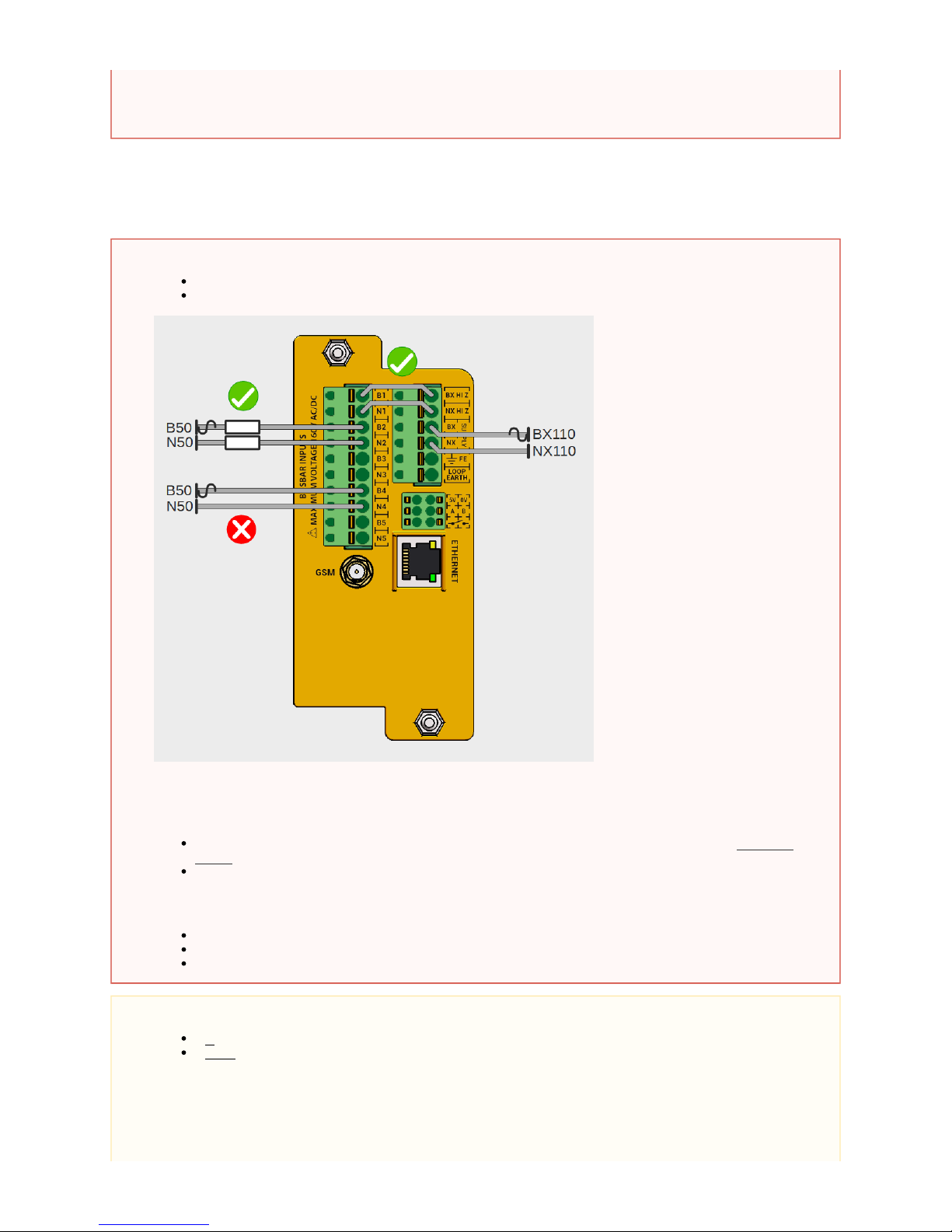
Never connect the SA380-IT directly to monitored circuits without:
Using the approved resistive cable (MPEC part No. SA380-IT-RC).
Connecting via the BX HI Z and NX HI Z terminals.
Never attempt to "common together" any conductors from differing monitored circuits.
Always check the voltage of the monitored and supply circuits:
Check each monitored or supply circuit does not exceed the specified maximum system voltage (160V RMS
).AC/DC
Ensure wiring of monitored or supply circuits is performed such that the cabling is not "live" until installation is
complete.
Attempting any of the above poses a risk of:
Circumvention if the inter-isolation of monitored circuits.
Short circuit of individual monitored circuits.
Electric shock.
The Functional Earth and Loop Earth must be connected to suitable earthing points using separate wires.
It acceptable to use a common earthing point if provision of a secondary earthing point is prohibitive.is
It acceptable to simply strap Functional Earth to Loop Earth.is not
Page 5
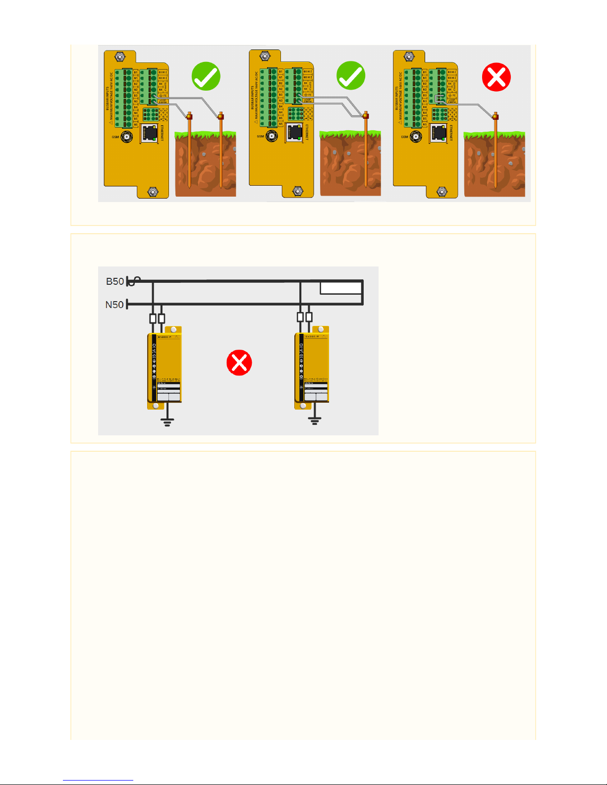
An ineffective Earth Loop circuit is unable to verify correct connection of the SA380-IT, hence insulation readings may be incorrect.
Only one insulation monitoring device may be used on a single interconnected circuit. Installation of additional monitoring devices
will cause each device to "fight" the other, resulting in incorrect readings on both devices.
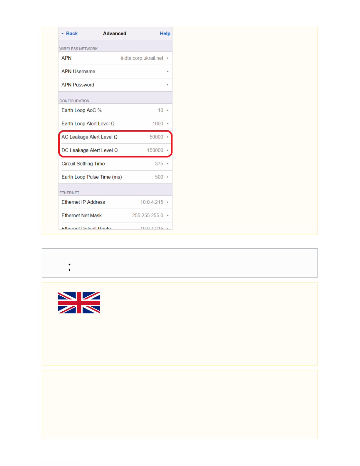
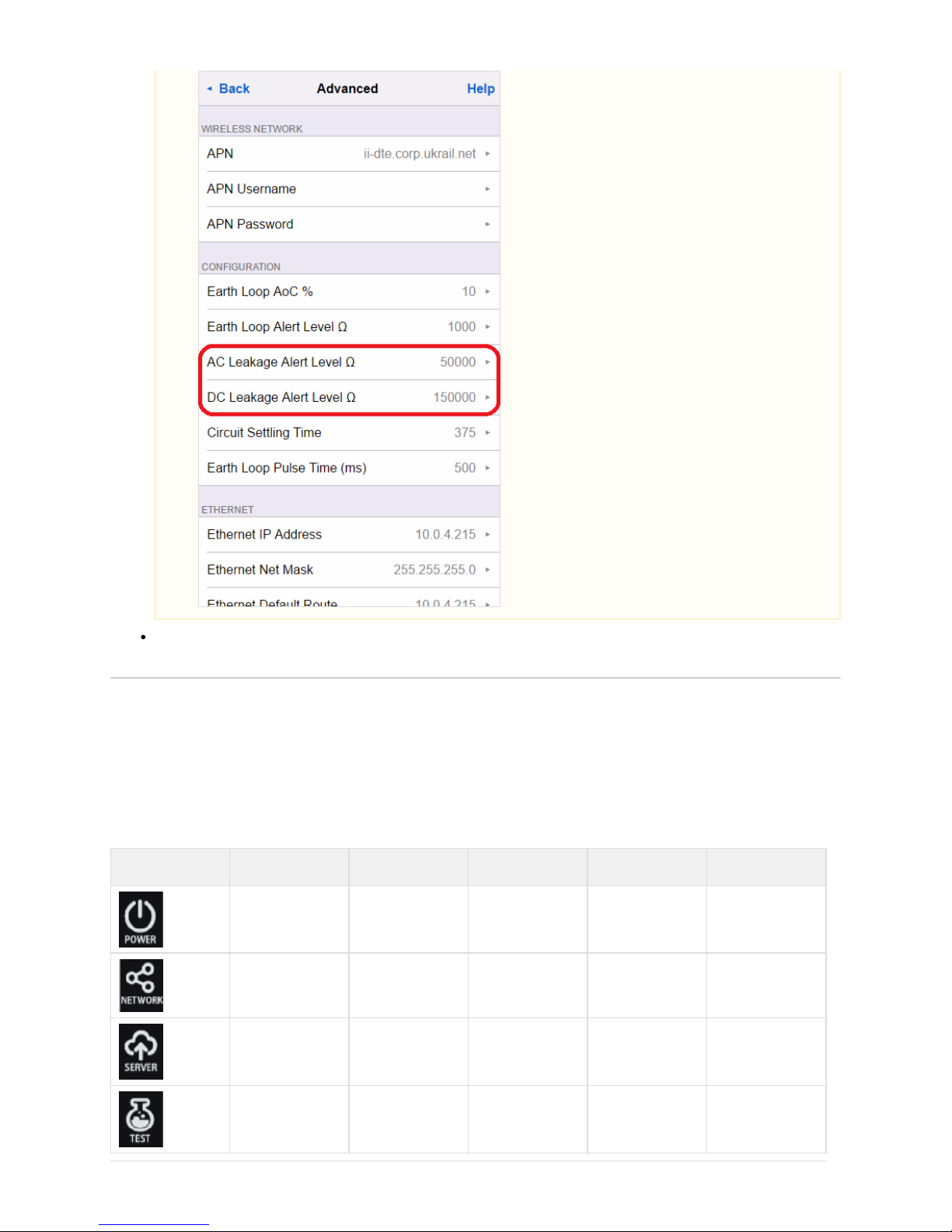
Check that the factory set earth loop and insulation resistance alarm levels are correct for your application. (See section 4.4.10)
REQUIRES NEW SCREENSHOT
Page 6
The Ethernet port is sensitive to electrical surges:
Additional surge protection be fitted if the port is to be used continuously for data transmission. must
Surge protection is for temporary configuration and diagnostics activities.not required
Limitations of use in the United Kingdom
The following restrictions upon use must be observed when the SA380-IT is deployed on UK rail infrastructure:
Never attempt to power the SA380-IT from a DC power source
Never attempt to wire any conductors from differing monitored circuits into the same input channel.
Users in other countries may disregard this warning.
No hazards have been identified if the above advice is not followed, but these practices are against UK railway policy.
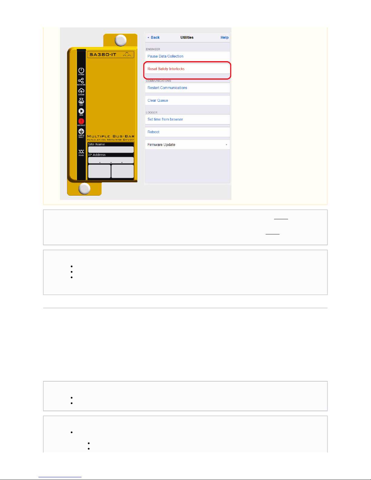
Ensure that you have exhausted all fault finding tasks prior to manually resetting any device interlock (see section 5.2 and section
4.4.5).
Page 7
2) General
2.1) Product Description
The SA380-IT is designed to facilitate the continuous monitoring of circuit voltage and resistance to earth of up to 5 independent circuits.
The SA380-IT has built-in communications hardware in the form of a GSM modem and features Ethernet connectivity. This allows the
SA380-IT to connect to cloud-based Enterprise Asset Management Systems (EAMS).
It is wise to conduct a on monitored circuits both prior to, and after installation, but energising themanual insulation test before
SA380-IT. This will help verify correct installation of the measurement circuit wiring.
A between Functional Earth and Loop Earth connections after installation, but energising SA380-ITmanual continuity test before
will help verify correct installation of the earth-loop circuit wiring.
When conducting manual insulation testing on monitored circuits after commissioning, the SA380-IT must be either:
Prevented from attempting measurement (see section 4.4.5).
Physically disconnected from the monitored circuit.
Powered-down.
Failure to do so will result in incorrect readings.
ontinuous monitoring. It facilitates:Maintenance Reduction and Failure prevention are best realised through c
The removal of the requirement for time-consuming and dangerous physical inspection and measurement.
The ability to predict, schedule and fix developing earth faults they become an operational risk.before
Key Features:
Independent monitoring of up to 5 circuits, each circuit can be one of the following systems:
Single phase IT AC system up to 160 V RMS.
Single phase IT AC system up to 160 V RMS with galvanically connected rectifiers.
Page 8
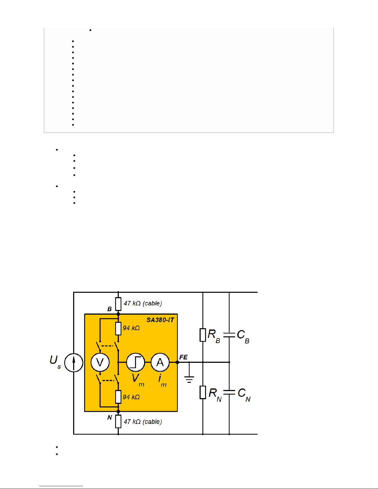
The SA380-IT has the ability to monitor and continuously report the following parameters:
For each monitored circuit:
System voltage.
For DC circuits, resistance to earth of individual circuit legs, R and R
B N.
For AC circuits, equivalent resistance to earth (R is measured. This is R and R in parallel.
L) B N
Resistance to earth alert status (resistance below pre-set threshold).
For each SA380-IT device:
Loop resistance between functional earth and loop earth terminals.
Earth Loop fault status.
Hardware fault status.
2.2) Principles of Operation
Monitored circuits remain galvanically isolated from one another at all times. Monitored circuits are only connected to measurement circuitry
and earth during measurement.
Periodic monitoring of the hardware and earth connection assures safe and reliable operation.
Inside the SA380-IT there is only one single instance of "measurement circuitry", however there are five instances of the "monitored circuit"
circuitry (switches and protection resistors).
Simplified voltage and resistance to earth measurement circuitry for one monitored circuit.
U = Monitored circuit voltage.
s
B = B leg circuit connection.
IT DC system up to 160 V RMS.
Equivalent resistance to earth measurement of AC circuits.
Resistance to earth measurement of each circuit leg of DC circuits.
Automatic adaptation to system leakage capacitance.
Sub 1 second rapid response time.
Adjustable response values.
Captures long-term average, as well as fast transient faults to earth
Detection of core-to-core cables faults.
Monitored circuits supply voltage measurement.
Earth-loop continuity measurement.
Continual self-test for accuracy and safety.
Volt-free contact alarm output.
Auxiliary power supply output.
In-built GSM communication.
In-built Ethernet communication.
In-built RS485 communication.
Compatible with leading enterprise asset management systems.
Page 9

N = N leg circuit connection.
FE = Functional earth circuit connection.
V = Internal voltmeter.
V = Measurement pulse voltage.
m
i = Resistance to earth ammeter.
m
R = Resistance to earth (B leg).
B
R = Resistance to earth (N leg).
N
C = System leakage capacitance (B leg).
B
C = System leakage capacitance (N leg).
N
An independent solid-state switch exists for each monitored circuit.
Independent internal protection resistors (94 k) exist for each monitored circuit.
Independent resistive cables (47 k) are provided for connection of each monitored circuit.
The modes of operation, and measurement principals of the SA380-IT are described in the following sections.
2.3) Modes of Operation
2.3.1 Normal Mode
Each monitored circuit (configured for measurement) is evaluated in turn, in a loop:
The monitored circuit is connected to the internal measurement circuitry and earth using a solid-state switch.
Voltage measurement is performed. (see 2.4)
If the voltage is in range, resistance to earth measurement is performed. (see 2.5)
The monitored circuit is disconnected from the internal measurement circuitry and earth.
the procedure is repeated for the next monitored circuit, and so on.
Every 60 seconds system integrity checks are performed:
Solid state switches are confirmed to be in the "open" state (all monitored circuits galvanically disconnected from each other,
measurement circuitry and earth).
The SA380-IT remains within its defined accuracy parameters (performs an internal calibration check).
Earth-loop resistance has not exceeded the alarm limit (resulting in inaccurate resistance to earth measurements).
2.3.2 Technicians Mode
For "on-site" use to aid a technician in locating and remedying monitored circuit faults. (see 4.4.3)
Forces the SA380-IT to make repeated measurements of a single monitored circuit.
Response time is increased as only the monitored circuit of interested is measured.
A large and clear read-out of measured values is reported to the technicians iPhone or computer display.
The technician can quickly verify if their actions are having the desired effect upon the monitored circuit.
Technicians mode can be cleared manually by the user at any time.
Technicians mode will automatically clear after a period of 4 hours, and the SA380-IT will resume "Normal mode".
Earth Loop resistance measurement and system safety tests are performed whilst in technicians mode.not
2.3.3 Suspended Mode
The user may suspend monitored circuit measurement to enable fault finding activities to take place. (See section 4.4.5). This prevents the
SA380-IT injecting a measurement pulse, or presenting resistances to earth across the monitored circuits.
During suspended mode, all monitored circuits remain galvanically isolated from each other, all internal measurement circuitry and
earth.
Suspended mode can be cleared manually by the user at any time.
Suspended mode will automatically clear after a period of 4 hours, and the SA380-IT will resume "Normal mode".
Earth Loop resistance measurement and system safety tests are performed whilst in suspended mode.not
2.3.4 Degraded Modes
There are instances when the SA380-IT may suspend some, or all measurements. Degraded modes are applicable in normal and
technicians mode and are often due to the activation of device safety interlocks. See section 5.2 for more information.
Scenario Voltage Measurement
of Monitored Circuits
Resistance to Earth
Measurement
of Monitored Circuits
Earth Loop &
Safety Tests
Device boot
No No No
Time not set
No No No
Page 10

Earth loop resistance out of
tolerance
No No Yes
Monitored circuit under voltage
Yes No - Affected Circuits
Yes - Unaffected Circuits
Yes
Monitored circuit over voltage
Yes No - Affected Circuits
Yes - Unaffected Circuits
Yes
Solid state switch fault
No No No
Calibration test failure
No No No
2.4) System Voltage Measurement
Voltage is measured across the monitored circuit terminals after the monitored circuit is connected to the measurement circuitry, but prior to
resistance to earth measurement.
If the circuit is configured for measurement, the value of the voltage is calculated.AC RMS
If the circuit is configured for measurement, the value of the voltage is calculated.DC mean
2.5) Resistance to Earth Measurement
Only if the monitored circuits voltage measurement is within tolerable parameters will a resistance to earth measurement be attempted. This
is to ensure safe and reliable operation of the monitored circuit.
The SA380-IT utilises the "pulse test" method of resistance to earth measurement. A series of current limited rectangular pulses are injected
into the monitored circuit. This will cause a current to flow through any resistance and capacitance to earth.
Any capacitance to earth will eventually become fully charged by the test signal. once this occurs, a current measurement can be taken in the
steady state. The combined values of capacitance and resistance to earth will govern measurement time.
2.5.1) AC and DC Circuits
Equivalent Circuit for Measurement Pulse signal
R = Equivalent Resistance to Earth (R in parallel with R ).
L B N
C = System Leakage Capacitance (C in parallel with C ).
E B N
i = Ammeter current solely due to measurement pulse voltage.
Vm
The graph below shows the application of measurement pulses, the transient charging current through the system capacitance and the
A voltage reading of less than 0.5 s regarded as an . times the configured nominal voltage i under-voltage (for example, a reading
Resistance to Earth will not be measured until the under-voltage is removed.of <=25 V on a circuit configured as 50 V).
A voltage reading of more than 1.45 times the configured nominal voltage is regarded as an (for example, a readingover-voltage
of >=72.5 V on a circuit configured as 50 V).
In the above scenarios, r Such an event be causedesistance to Earth will not be measured until the voltage error is removed. could
by hardware failure, but is often simply due to supply voltage variation.
Page 11
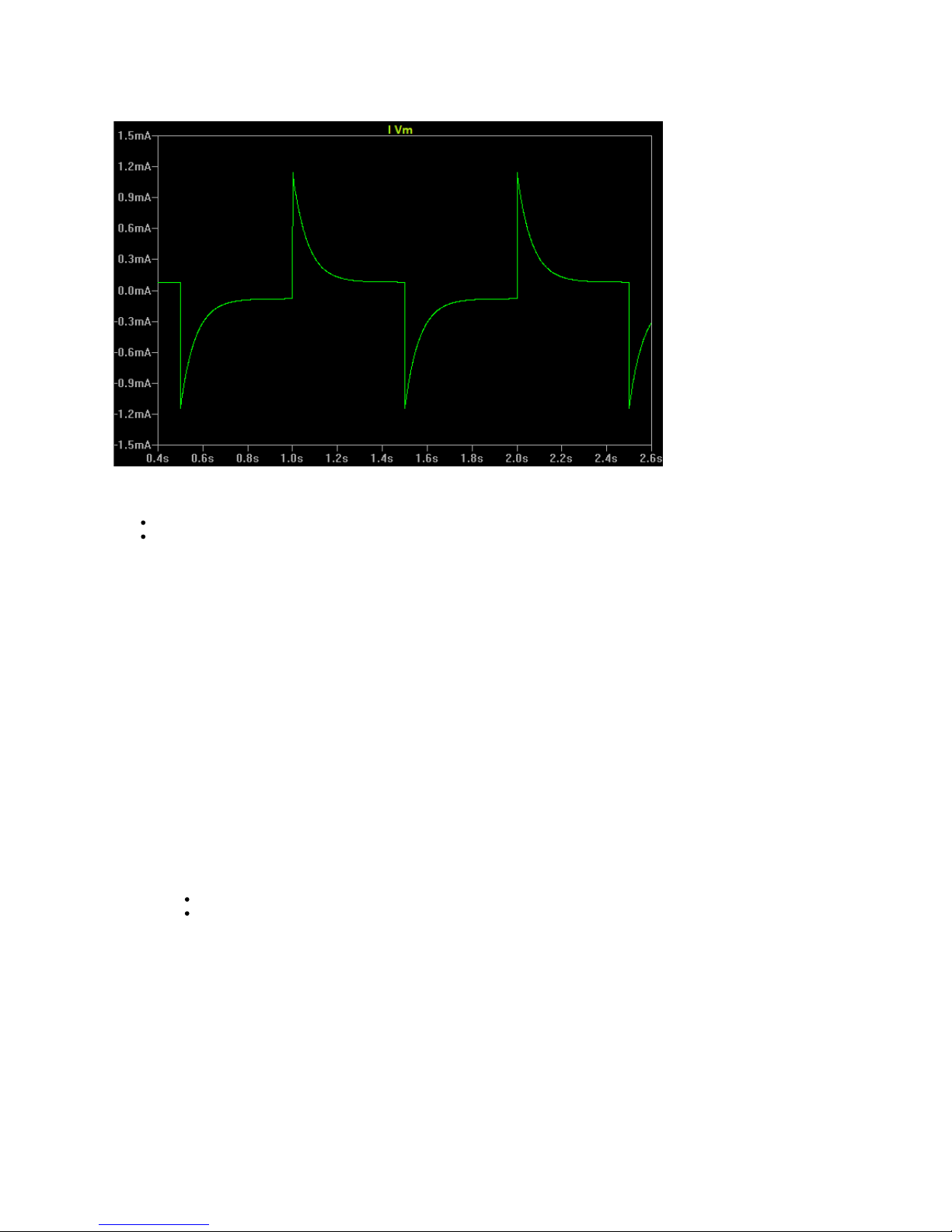
eventual steady state condition:
Typical response to measurement pulses
The SA380-IT configurable "measurement timeout" parameters place limits on how long the device will wait for the steady state to be
achieved prior to taking a measurement. This time may be exceeded if:
The system capacitance and resistance are too high.
Transient signals present in the measurement loop prevent a steady state being achieved.
Transient signals may be due to sudden monitored circuit voltage variation, or transient resistance to earth events. Unstable circuit voltage
may also prevent the steady state being achieved.
Measurement Procedure:
Fast Scan
Rapid response time is achieved by performing resistance to earth measurements at high speed.
The timer setting (see section xxxx) governs how quickly the SA380-IT attempts measurement of each circuit. By default this fast scan
value is set to 1000 ms, meaning that measurement is performed within 1 second for each monitored circuit, giving a maximum cycle
time of 5 seconds for a fully utilised SA380-IT device.
If the steady-state can not be achieved in the fast-scan period, offending circuits are scheduled for a periodic slow scan. These slow
scans allow accurate measurement of high-resistance-to-earth, capacitive circuits, albeit a at a slower speed.
Slow Scan
Circuits that can not achieve steady state during the fast-scan period are measured during the slow-scan period. The timer slow scan
parameter control this frequency. (See section xxxx). By default this value is set to 5 minutes. Once every five minutes a slow scan is
performed on circuits that have repeatedly failed fast-scan readings. The period of time that the SA380-IT can spend performing
slow-scans is limited to 50% of total measurement time of the entire SA380-IT device, assuring that the fast-scan process still has time
to run.
If the slow scan fails, The SA380-IT still attempts measurement and displays one of the following:
If resistance-to-earth is estimated to be >= 5 M, then 5 M is displayed and the slow-scan is deemed to have succeeded.
If resistance-to-earth is estimated to be < 5 M, then the estimated reading is displayed on the user-interface alongside the
message "Unstable" and the slow-scan is deemed to have failed.
Spot-Readings
The successful result of a fast or slow scan is known as a spot reading. For circuits with little capacitance / low resistance-to-earth then
a spot-reading will be taken once every 1 to 5 seconds. A circuit with high capacitance / resistance-to-earth may record a spot reading
once every 5 minutes.
The latest Spot-readings are displayed on the user interface. If a spot-reading crosses an alert boundary (see section xxx), then the
latest average and spot-reading messages are sent to the EAMS to alert the maintainer of the transient fault condition.
Average Readings
Successful spot-readings are also used to calculate the long-term-mean resistance to earth of a circuit. The snapshot timer setting
governs how frequently these average readings are reported to the EAMS. By default, this period is set to 1 hour
The average is reset when the following occurs:
Page 12
When the snapshot period elapses (default 1 hour)
When a transient spot-reading crosses an alert boundary (at any time)
Benefits
Through the balance of fast and slow scan, spot-reading and average readings the SA380-IT is able to achieve:
Rapid measurement and detection of transient earth faults.
Accurate measurement of high resistance / capacitive circuits
Stable Readings of circuits with a high resistance to earth
In addition to the above methods, the SA380-IT applies proprietary signal conditioning algorithms to improve measurement accuracy
under transient conditions, such as:
Unstable monitored circuit voltage.
Dynamic resistance to earth changes.
Transient events on monitored circuits.
2.5.2 DC Circuits Only
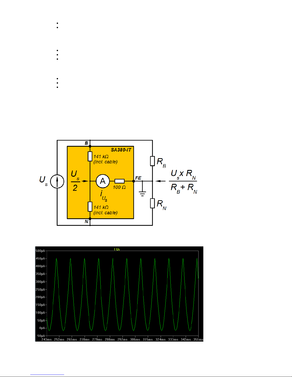
In a DC circuit, the Resistance to earth of each circuit leg can cause current flow from the monitored circuits supply U , through SA380-IT
s
measurement circuitry. For DC sources, such a current will always appear to flow in the same "direction" through the measurement circuit,
regardless of measurement pulse polarity.
The equivalent circuit and associated current trace are shown below:
i = Ammeter current solely due to monitored circuit voltage "bleed through" in a DC circuit.
Us
The net current flow measured by the internal ammeter is the sum of the current produced by the test pulse voltage and the current caused
by the monitored circuit voltage "bleeding through" the SA380-IT.
Page 13
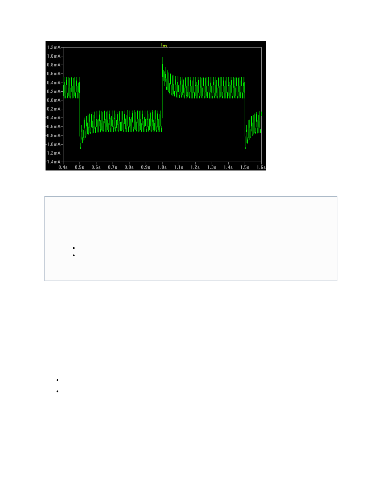
The graph below shows a typical measurement current trace of the SA380-IT:
By applying a test pulse of alternating polarity, the test pulse current becomes a "differential" current reading, whilst the current due to the
supply circuit becomes a "common" current reading.
2.6) Core-to-Core Resistance Effects
2.7) Earth Integrity Measurement
Every 30 seconds the integrity of the SA380-IT functional earth connection is validated by measuring the resistance between the primary
(Functional Earth) and secondary (Loop Earth) earth connections.
This gives confidence that the earth connection is "good" and therefore reliable Resistance to Earth measurement of monitored circuits can
be conducted.
In the case where two wholly independent earth points have been provided (1), it verifies that the functional earth connection is
intact, and that connection to the physical mass of the earth is also of sufficiently low resistance.
In the case where two independent wires have been run to a common earth point, (2) it verifies that the wiring of the functional earth
connection is intact.
Single & Double Earth Points:
By taking the difference of the measured current for the positive and negative measurement pulse signals, the "common" current is
eliminated allowing the calculation of equivalent resistance to earth (R ).
L
By taking the sum of the measured current for the positive and negative measurement pulse signals, the "differential" current is
eliminated. In the case of DC circuits, this allows the direct calculation of the resistance of each circuit leg R and R .
B N
Please note:
When R > 20 x R . Then the accuracy of
B N
R will B exceed +/-5%
When R > 20 x R . Then the accuracy of
N B
R will N exceed +/-5%
This is due to it becoming increasingly difficult to measure a large resistance to earth in one leg of a circuit, when the resistance to
earth in the other leg of the circuit becomes relatively small.
Page 14
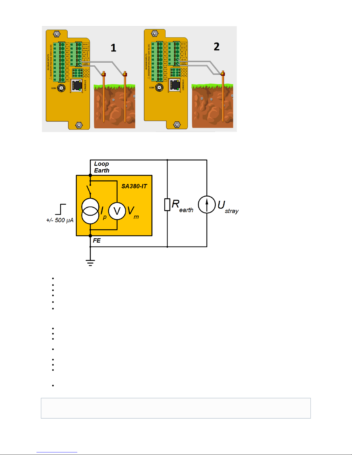
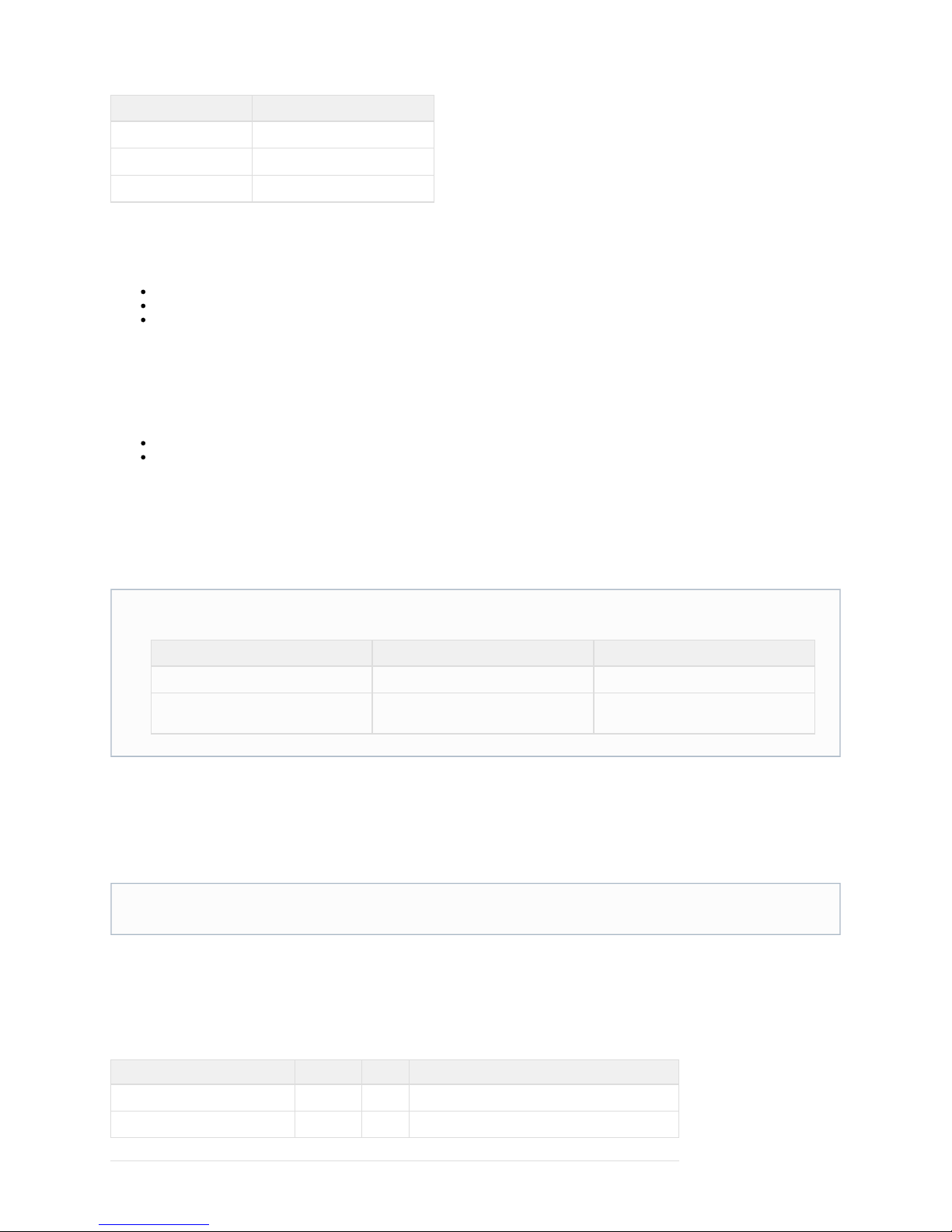
The Resistance of the earth loop is measured in a manner very similar to "Resistance to Earth of Monitored Circuits".
Equivalent Circuit for Earth Loop Measurement:
I = Measurement Pulse Current.
p
Loop Earth = Loop Earth terminal.
FE = Functional Earth circuit terminal.
V = Measured Voltage (High Impedance).
m
R = Earth Loop Resistance.
earth
U = Voltage due to stray Earth Currents.
stray
Measurement Procedure:
When the Earth Loop Resistance is not being measured, the current source is disconnected from the measurement circuit.
When measuring Earth Loop Resistance, a "pulse test" method of earth loop resistance measurement is employed.
A series of constant-current, rectangular pulses are injected into the monitored circuit. This will cause a constant current to flow
through any resistance in the earth loop path.
The constant current generates a voltage across the earth loop resistance. It is this voltage that is acquired by the measurement
circuitry. Voltage is limited to 3.5 V in the open circuit case.
Unwanted voltage will also be picked up by the measurement circuitry due to stray ground currents flowing in the earth loop.
Unwanted stray AC components above 3.5Hz are removed using digital filtering techniques.
The unwanted stray DC component is removed through the use of a bi-directional current source, similar to resistance to earth
measurement, the constant measurement pulse presents as a differential signal across the measuring element, whilst the stray DC
current appears as a common signal across the measuring element.
Measurement takes approximately 300 milliseconds.
By taking the difference of the measured voltage for the positive and negative measurement pulse signals, the "common" current is
eliminated allowing the calculation of Earth Loop Resistance (R )
earth
Page 15

2.8) Hardware Self-Test
Hardware self-test is undertaken every 30 seconds. The SA380-IT will report a hardware-fault when the following conditions occur:
The SA380-IT is unable to make reliable measurements of insulation resistance.
The SA380-IT has detected an internal fault that could impact upon the safety or reliability of the monitored system.
The SA380-IT response to these scenarios is as follows:
Indicate to the cloud based supervisory system that a hardware fault has occurred.
Illuminate the light.HW FAULT
Open the volt-free contact output.
Disable the faulty hardware. (Device Interlock)
These "device interlocks" will prevent further measurements being conducted.
2.9) Alert Conditions
The SA380-IT raises alerts under the following scenarios:
Scenario Self-Clearing ? Locks Out: Lights HW Fault
Lamp?
Lights Earth Fault
Lamp?
Opens Volt-Free
Contact?
Under Voltage
Yes Channel No No No
Over Voltage
No Channel Yes No Yes
Calibration test
failure
No Device Yes No Yes
Solid state switch
fault
No Device Yes No Yes
Earth loop
Resistance above
Alert Threshold
Yes
5% Hysteresis
Device Yes No Yes
Resistance to Earth
below Alert
Threshold
Yes
5% Hysteresis
N/A No Yes Yes
2.8.1 Hysteresis:
Hysteresis is employed to prevent "chattering" alerts:
When the resistance to earth of a monitored circuit drops below the configured the SA380-IT will enter the alert threshold earth
state.fault
E.g. if the alert threshold is 100 k, an "earth fault" will be flagged as soon as resistance to earth drops below 100 k on any
monitored circuit.
The earth fault will remain until the resistance to earth of a monitored circuit exceeds the configured alert threshold +5%.
E.g. the earth fault would not "clear" until the resistance to earth exceeds 105 k on monitored circuits.all
When the earth loop resistance exceeds the configured the SA380-IT will enter the state. alert threshold hardware fault
E.g. if the alert threshold is 1 k, a "hardware fault" will be flagged as soon as earth loop resistance exceeds 1 k.
The hardware fault will remain until the earth loop resistance drops below configured alert threshold -5%.
E.g. the hardware fault would not "clear" until the earth loop resistance falls below 950 .
2.8.2 Minimum Operation Time
If any fault condition causes the volt-free contact to open, it shall remain open for a minimum period of 2 seconds to prevent the risk of
transient events being missed.
2.10) Communications & Peripheral Outputs
2.9.1 Fault Indication (Volt-Free-Contact)
The SA380-IT features a volt-free contact (relay) output. This can be utilised to:
Indicate fault conditions to external alarm circuits
Connect to external data-logging equipment.
The latter is particularly useful, as additional event data from the data logging device can be used to cross-check which sub-elements of a
Page 16
monitored circuit are active in the event of transient earth faults.
Fault contact open Fault contact closed
SA380-IT powered down SA380-IT powered and fault free
Hardware fault
Earth fault
2.9.2 Auxiliary Power Supply
A external power supply is provided to power external sensors or equipment. The specification is:
5 Volts
1 Watt
Galvanically isolated from all other circuits except for RS485.
2.9.3 Serial RS485 Data Port
A serial RS485 port is provided to allow serial data communications between the SA380-IT and another device.
These features are yet to be implemented in software, but are envisioned to facilitate the following:
Connection to MPEC SA380TX data loggers
Connection to smaller down-stream earth continuity or earth leakage testers and sensors.
2.9.4 GSM & Ethernet Connection
The SA380-IT features an internal GPRS modem with factory fitted SIM, and an Ethernet controller. Configuration of the SA380-IT and
reporting of data is possible using both interfaces.
Both communication bearers allows continuous reporting of all measured values to an Enterprise Asset Management System (EAMS).
Operation and configuration of these Enterprise asset management systems is beyond the scope of this user guide.
On-site configuration via Apple devices, such as iPhone or iPad, is supported via a "Lightning to Ethernet" cable connected between Apple
device and SA380-IT.
A custom App named " " is available from the Apple AppStore that supports this cable. (See section 4.3.1 for details).SA380-IT
Configuration and interrogation is explored in depth in section 4.4.
2.11) Data Acquisition
The SA380-IT processes data before display to the user and transmission to an Enterprise Asset Management System. (EAMS)
The following quantities are sampled and sent back to the EAMS:
Name Quantity: Units: Notes
Monitored Circuit Voltage
U
m
V Reported for all five circuits
Resistance to Earth (Negative Leg)
R
N
k Reported for all five circuits
Enterprise asset management systems can be be utilised to monitor long term asset trends and forewarn of asset failure. Presently
two such systems are supported:
Product Vendor Web-Link
Centrix MPEC Centrix Documentation
Network Rail Intelligent Infrastructure Network Rail / Thales http://www.networkrailconsulting.com/s
ervice/remote-condition-monitoring
The Lightning to Ethernet Cable (MPEC part number SA380-IT-LE) is sold as a separate accessory and is not normally included
with the device (see section 6.3).
Page 17

Resistance to Earth (Positive Leg)
R
B
k Reported for all five circuits
Earth Loop Resistance
R
E
Unit Status
Status NA Collection of binary status information (see table below)
Temperature
Temp
o
C
Internal temperature
Up-Time
Time minutes Period of time since last restart
Signal Strength
GSM Signal dB GSM modem signal strength
Note that for AC monitored circuits, R = R and R = R
B L N L.
The status message is a 16-bit integer. with '0' being false, and '1' being true. Each bit has the following meaning:
Bit Meaning
0
Calibration Fault
1
Internal Hardware Fault
2
Calibration or Hardware Fault; or device in suspended mode
3
Earth Loop Fault
4
Any Monitored Circuit has an Over voltage
5
Not used
6
Volt Free Contact State (0 closed, 1 open)
7
Not used
8
Not used
9
Not used
10
Internal Monitored Circuit Fault
11
Monitored Circuit 1 Fault
12
Monitored Circuit 2 Fault
13
Monitored Circuit 3 Fault
14
Monitored Circuit 4 Fault
15
Monitored Circuit 5 Fault
2.10.1 Protocol Selection
Two transmission protocols can be selected for sending data to an EAMS:
MIMOSA
Text based protocol compatible with the Network Rail Intelligent Infrastructure and MPEC Centrix systems.
Plain text, human-readable, but large data messages.
Lengthy back-off periods (up to 2 hours) in the event of loss of communications.
Does not support engineering units.
RailDAQ
Binary protocol compatible with the MPEC Centrix system.
Small, but unreadable binary messages (more than 10 times smaller than MIMOSA).
Minimal back-off periods (a few seconds) in the event of loss of communications.
Message size and back-off policy offer significant reliability improvements over MIMOSA.
Supports engineering units.
2.10.2 The Rules of Acquisition
Rounding and Truncation
After performing a measurement, the software will round and cap all data to make it simpler to interpret.
Page 18
Quantity: Rounding: Capping:
Monitored Circuit Voltage
U
m
to the nearest 1 V 160 V
Resistance to Earth
R R
B N
down to the nearest 1 k 5 M
Earth Loop Resistance
R
E
to the nearest 0.5 1 k
It is the rounded and capped data is displayed on the web based user interface.
Sampling
Data is not continuously sampled and sent the EAMS as this would produce a vast amount of data.
The SA380-IT employs a sampling scheme that rationalises the amount of data buffered for transmission by employing the following
sampling rules.
State U
M
R
N
R
B
R
E
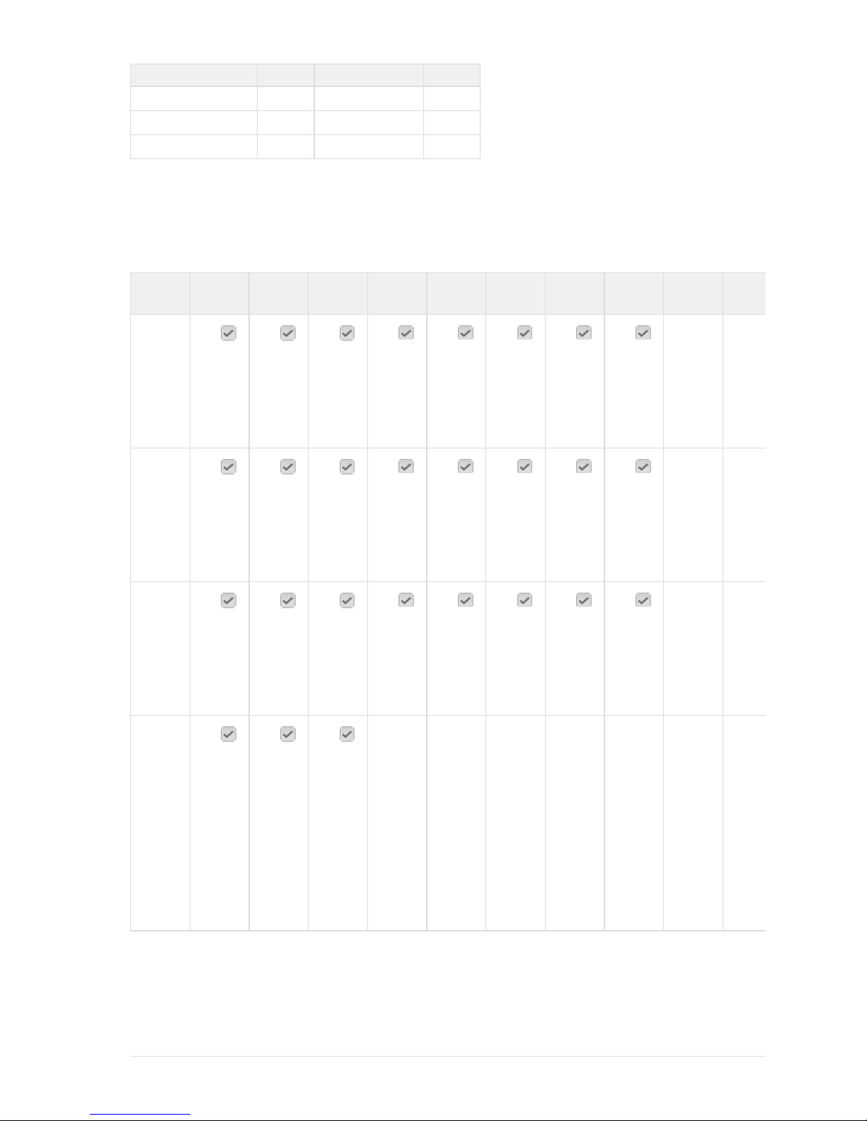
Status Temp Time GSM
Signal
Notes Factory
Default
Setting
At start-up
a
l
l
c
i
r
c
u
i
t
s
a
l
l
c
i
r
c
u
i
t
s
a
l
l
c
i
r
c
u
i
t
s
Sample
acquired as
soon as time
is set
NA
snapshot
time elapsed
since last
acquisition
a
l
l
c
i
r
c
u
i
t
s
a
l
l
c
i
r
c
u
i
t
s
a
l
l
c
i
r
c
u
i
t
s
snapshot
time is
configurable.
The snapshot
timer runs
"per channel"
1 hour
User clears
"comms
queue"
a
l
l
c
i
r
c
u
i
t
s
a
l
l
c
i
r
c
u
i
t
s
a
l
l
c
i
r
c
u
i
t
s
NA
% change in
Um
a
f
f
e
c
t
e
d
c
i
r
c
u
i
t
o
n
l
y
a
f
f
e
c
t
e
d
c
i
r
c
u
i
t
o
n
l
y
a
f
f
e
c
t
e
d
c
i
r
c
u
i
t
o
n
l
y
% change is
configurable
5%
Page 19

% change in
R
L
a
f
f
e
c
t
e
d
c
i
r
c
u
i
t
o
n
l
y
a
f
f
e
c
t
e
d
c
i
r
c
u
i
t
o
n
l
y
a
f
f
e
c
t
e
d
c
i
r
c
u
i
t
o
n
l
y
% change is
configurable
5%
% change in
the lower
value of aR
B
nd R
N
a
f
f
e
c
t
e
d
c
i
r
c
u
i
t
o
n
l
y
a
f
f
e
c
t
e
d
c
i
r
c
u
i
t
o
n
l
y
a
f
f
e
c
t
e
d
c
i
r
c
u
i
t
o
n
l
y
% change is
configurable
5%
% change in
R
E
% change in
REis
configurable
5%
Any change
is Status
NA
% Change:
A acquisition is made when the last measurement made by the hardware differs by more than from the reading at the% change n%
time of the last acquisition.
For example, if at start up. a value of R = 100 k, and the change threshold is set to 5%, then a acquisition will not be take
N
% change
place until a reading <= 95 k, or >= 105 k is made.
Delayed acquisition:
60 seconds after any of the above acquisitions takes place, a further delayed acquisition is made to ensure that the EAMS knows that
the readings are stable and representative.
The 60 second time-out period is user configurable.
2.10.3 Buffering
Queue
Every time an acquisition takes place, if is placed in a first-in, first-out (FIFO) message queue. This message queue resides in
non-volatile memory and will not be erased when the SA380-IT powers-down.
The SA380-IT will attempt to empty this queue whenever a successful connection to an EAMS exists.
When the queue becomes full, the oldest entries are over-written.
The user can empty the queue at any time.
The queue has enough room for approximately 130,000 acquisitions. This is at least 1.5 days of data at absolute maximum
acquisition rates, or 9 months of data at a stable installation. Your mileage may vary.
Batching
When using MIMOSA communication the SA380-IT will hold-off the transmission of data until one of the following conditions becomes
true.
>= 1024 entries are pending in the queue.
>=60 seconds has elapsed since a message was last transmitted.
This is to economise transmission bandwidth and server resources.
Page 20
2.10.4 Examples
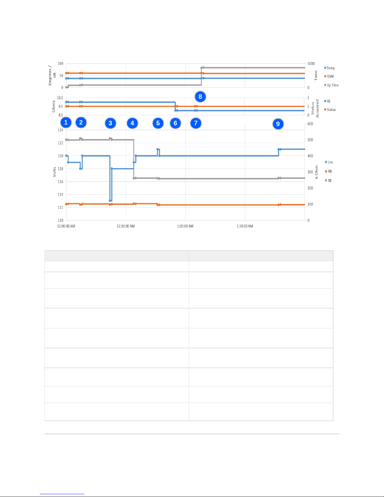
The diagram below shows examples of each type of acquisition:
In all cases two acquisitions take place for each event, the initial triggered acquisition, and the subsequent delayed acquisition 60 seconds
later.
Item Description
1
Acquisition on all channels due to device start-up
2
Acquisition on all channels due to user clearing the message
queue
3 Acquisition of Um, RN and RB due to a change in Um of >+/-5%
since the last acquisition of U
m
4 Acquisition of Um, RN and RB due to a change in RL of >+/-5%
since the last acquisition of RN and R
B
5 Acquisition of Um, RN and RB due to a change in RN (The lower of
RN & RB) of >+/-5% since the last acquisition of RN and R
B
6 Acquisition of RE and Status due to a change in RE of >+/-5%
since the last acquisition of R
E
7 Acquisition of RE and Status due to a change in Status since the
last acquisition of Status
8 Acquisition of Up-Time, Temp and GSM Signal due to a period of
1 hour elapsing since their last acquisition (snapshot)
9 Acquisition of Um, RN and RB due to a period of 1 hour elapsing
since their last acquisition (snapshot)
3) Installation
Page 21
3.1) Overview
Before commencing installation please consider the following:
The SA380-IT back panel is reproduced below showing the connector layout:
It is wise to conduct a on the monitored circuits both prior to, and after installation, but energisingmanual insulation test before
the SA380-IT. This will help verify correct installation of the measurement circuit wiring.
A between Functional Earth and Loop Earth connections after installation, but energising SA380-ITmanual continuity test before
will help verify correct installation of the earth-loop circuit wiring.
Check all fuses / links are at the system termination point for each monitored circuit and the SA380-IT power supply priorremoved
to installation. Test all wiring re-inserting any fuses / links.before
Only one insulation monitoring device may be used on a single interconnected circuit. Installation of additional monitoring devices
will cause each device to "fight" the other, resulting in incorrect readings on both devices.
Page 22
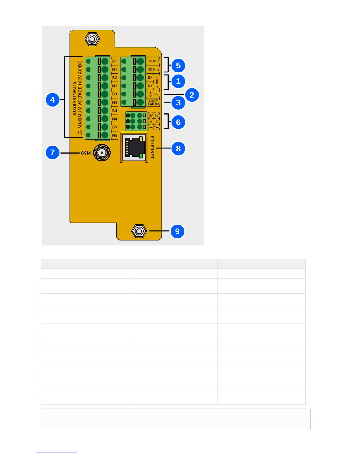
The principal connections are as follows:
No. Name Description
1 Supply
Power supply to the SA380-IT
2 Functional Earth
Common Earth point for all device
measurement
3 Loop Earth
Secondary Earth point for earth continuity
measurement
4 Monitored Circuits
The IT circuits that require insulation
monitoring
5 HiZ Outputs
A means of safely monitoring the insulation
of the supply circuit.
6 Auxiliary Outputs
I/O to other devices and alarm circuits
7 GSM Antenna
Facilitates GSM connection to an
Enterprise Asset Management System
8 Ethernet Jack
Allows local configuration and diagnostics,
or Ethernet connection to an Enterprise
Asset Management System
9 Fixing Stud
M5 mounting studs to fit BR930 / Q Style
relay mountings. Brackets are available to
allow alternate mounting arrangements
"Typical circuits" to Network Rail standards show the wiring arrangement of a typical installation.
Page 23
3.2) Physical Installation
The following precautions must be taken during storage and transportation:
Protection from prolonged rainfall.
Protection from immersion in water.
Ensure that the storage temperature is not exceeded.
Protection against crushing
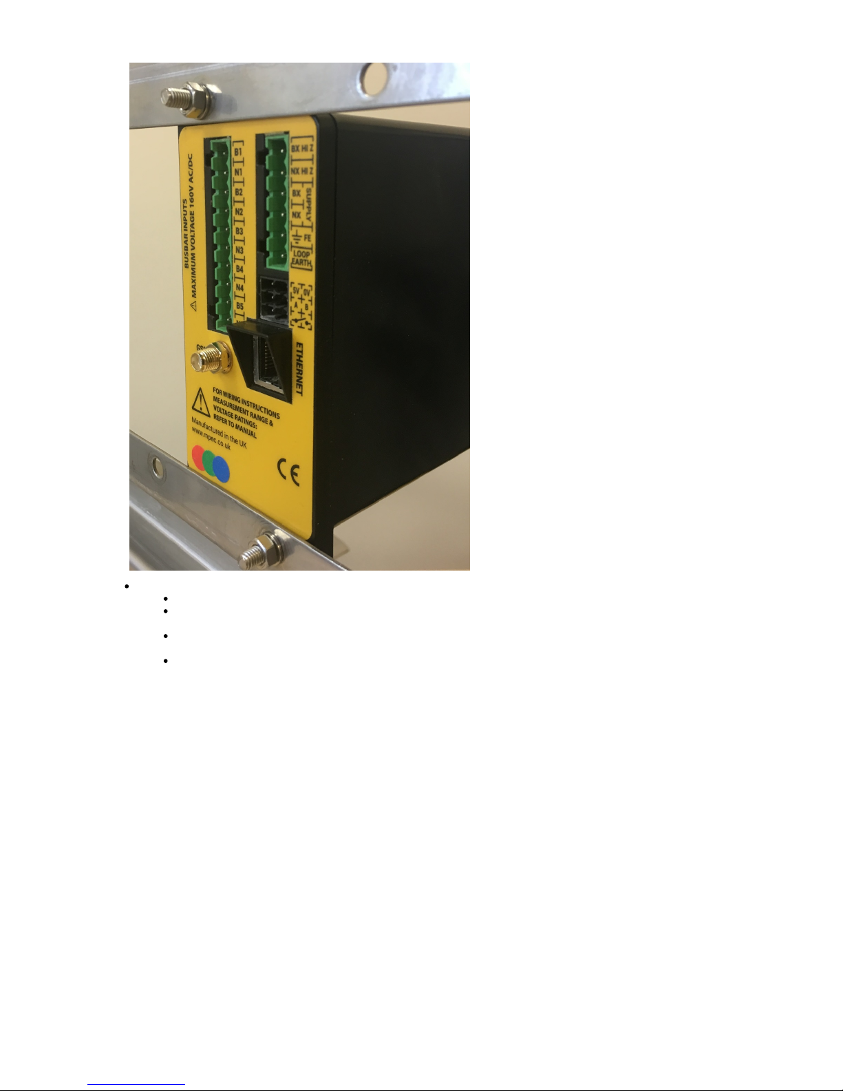
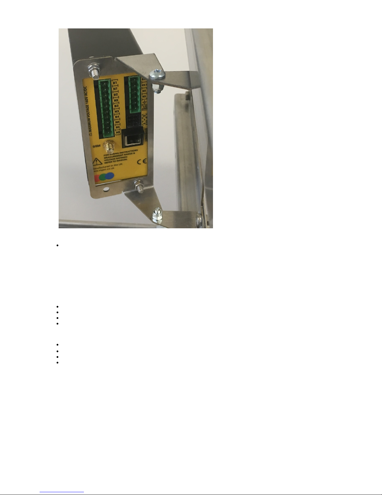
The SA380-IT is designed to be fitted to BR930 / Q Style relay bar. Alternative mounting arrangements can be made using the hinged
bracket (MPEC part no: BRK-HINGE)
Tool / Parts Required:
M5 (8 mm) nut spinner
Actions:
Install onto BR930 / Q Style relay racking. Feed the mounting studs through the pre-drilled holes on the mounting bar and secure
with the supplied spring washer and M5 nut. Take care not to over-tighten.
Damaged enclosures can expose hazardous voltages and nullifies the SA380-IT Ingress-Protection.
Prolonged exposure to, or immersion in water exceeds the SA380-IT Ingress-Protection rating. Under such conditions
dielectric withstand voltages cannot be guaranteed.
Never install or energise an SA380-IT that appears to be either physically damaged or suffering from water ingress.
Page 24
Alternatively install using the MPEC hinged bracket:
Orientate the bracket such that he hinge faces the desired side.
Affix the hinged bracket in the desired location using appropriate fixings (not supplied) through the pre-drilled holes at the
of the hinged bracket.rear
Feed the mounting studs of the SA380-IT through the pre-drilled holes at of hinged bracket and secure with thethe front
supplied spring washer and M5 nut. Take care not to over-tighten.
Lock the hinge of the bracket in place by tightening the M5 hinge nuts.
Page 25
Test:
Attempt to rock the device from the front of the enclosure. Check that the device is secure.
3.3) Termination of Wiring
It is recommended that terminations into the SA380-IT are made using ferules. Termination of cables onto monitored circuits and power
supplies etc. is beyond the scope of this user manual.
Tools / Parts Required:
Shrouded Ferrules: WEIDMULLER H0,75/16 W SV INSULATED FERULE. P/N: 9025860000
Un-shrouded Ferrules: WEIDMULLER H1,5/10 UNINSULATED FERULE. P/N: 0186500000
Crimp Tool: WEIDMULLER PZ 10 SQR WIRE END FERULE CRIMPER. P/N: 1445080000
Small flat-bladed screwdriver
Actions:
For 0.75 mm wire, use the crimp tool to affix a shrouded ferrule to the cable end.
2
For 1.50 mm wire, use the crimp tool to affix a un-shrouded ferrule to the cable end.
2
To insert a cable, push-home the ferrule into the spring-clamp plug.
To remove a cable, release the spring clamp using a small flat bladed screw driver prior to withdrawing the cable.
Page 26
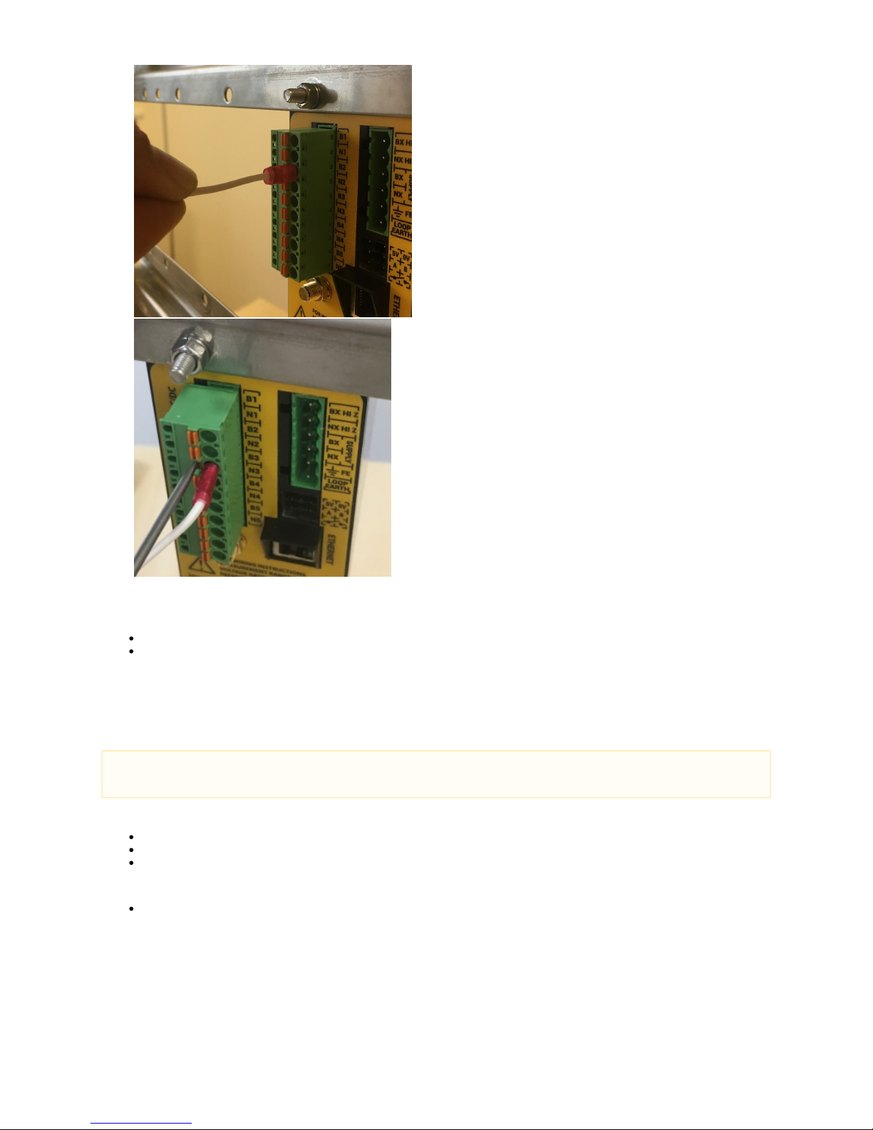
Wire insertion (Left) and removal (right)
Test:
Inspect that no copper strands are visible in the completed termination
Apply a sharp pull on the wire to ensure that the wire is properly gripped.
3.4) Connection of SA380-IT Supply
The SA380-IT requires an AC supply at the "BX" and "NX" supply terminals to operate.
Tools / Parts Required:
Ferrules
Crimp Tool
2A (minimum) fuse
Actions:
Connect the power supply to the SA380-IT as shown:
The SA380-IT is intended be powered from an AC circuit, however the device will operate when powered from a DC circuit with
appropriate voltage. This is not permitted in UK railway signalling systems.
Page 27
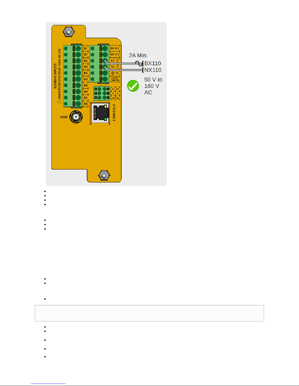
Do not use "resistive cable" for these terminations.
Network Rail users must use "Grey 0.75 mm A1" cable (supplied with the device) for these terminations.
A 2A fuse should be fitted in the "BX" leg of the supply.
Do not apply power to the device until all wiring is complete.
Test:
Test that the voltage of the circuit intended to power the SA380-IT is within 50 V to 160 V AC prior to connection.
Continuity test the "BX" wire end-to-end. The spring-contact plug of the SA380-IT features a test-point.
Continuity test the "NX" wire end-to-end. The spring-contact plug of the SA380-IT features a test-point.
3.5) Connection of Earth
The SA380-IT has two earth termination points. Both must be correctly installed for the device to function. See section 2 for a full description
of the function of SA380-IT earth terminals.
Tools / Parts Required:
Ferrules
Crimp Tool
Actions:
FE, or "Functional Earth" is the "master" earth point.
"Loop Earth" is used for performing earth-loop-continuity measurement.
The preferred method of installation is to bond "loop-earth" to a second earth bonding point, connected to the physical mass of the
earth and independent of the "FE" connection.
In this instance, the earth-loop-continuity test is checking the integrity of the cabling between SA380-IT to earth bonds, and
the integrity of the earth bonds to the mass of the earth.
Such a connection is shown on the left in the diagram below.
Where it is prohibitive to install and independent secondary earth bonding point, it may be deemed tolerable to wire the "Loop Earth"
the same earth bonding point as "FE". The Loop Earth bond must be independent to the FE bond.
FE must bonded to a main earthing point of the monitored electrical installation using as short and direct a cable
run as possible
Page 28
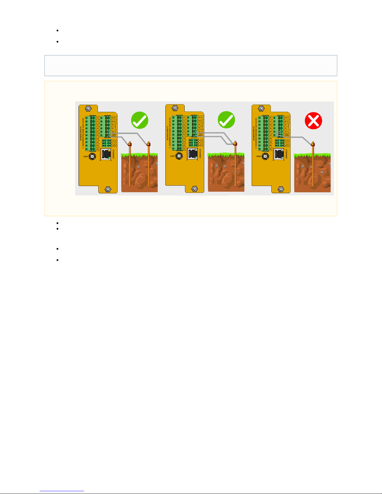
In this instance, the earth-loop-continuity test is only checking the integrity of the cabling between SA380-IT to earth bond,
and not the integrity of the earth bond to the mass of the earth.
Such a connection is shown in the middle of the diagram below:
Do not use "resistive cable" for these terminations.
Network Rail users must use "Yellow/Green 1.50 mm A1" cable (not supplied with the device) for these terminations.
Test:
Continuity test the earth loop between "FE" and "Loop Earth" connections. The spring-contact plug of the SA380-IT features a
test-point.
If using independent earth points, continuity test FE and Loop Earth separately as testing the loop resistance with a multi-meter may
give erroneous results. (FE to primary bond, then Loop-Earth to secondary bond).
3.6) Connection of Monitored Circuits
There are two means of connecting monitored circuits to the SA380-IT. Via resistive cables, or via the HiZ outputs:
3.6.1 Via Resistive Cables
This is the standard method of connection to monitored circuits
The SA380-IT device is typically supplied with resistive cables, or they can be purchased separately (see 6.3). The resistive cable features a
47 k series resistor fitted 100 mm from one end of the cable.
The purpose of the resistive cables are to limit current flow between monitored circuits in the event that any SA380-IT cabling inadvertently
comes into contact with any other safety critical or high reliability circuits.
In all cases Loop Earth must bonded to an earthing point of the monitored electrical installation using as short and
direct a cable run as possible.
Never connect Loop Earth to FE via a short strap connection at the rear of the unit as this will not prove the integrity of the
cabling between SA380-IT to earth bond, nor the integrity of the earth bond to the mass of the earth.
An ineffective Earth Loop circuit is unable to verify correct connection of the SA380-IT, hence insulation readings may be
incorrect.
Page 29
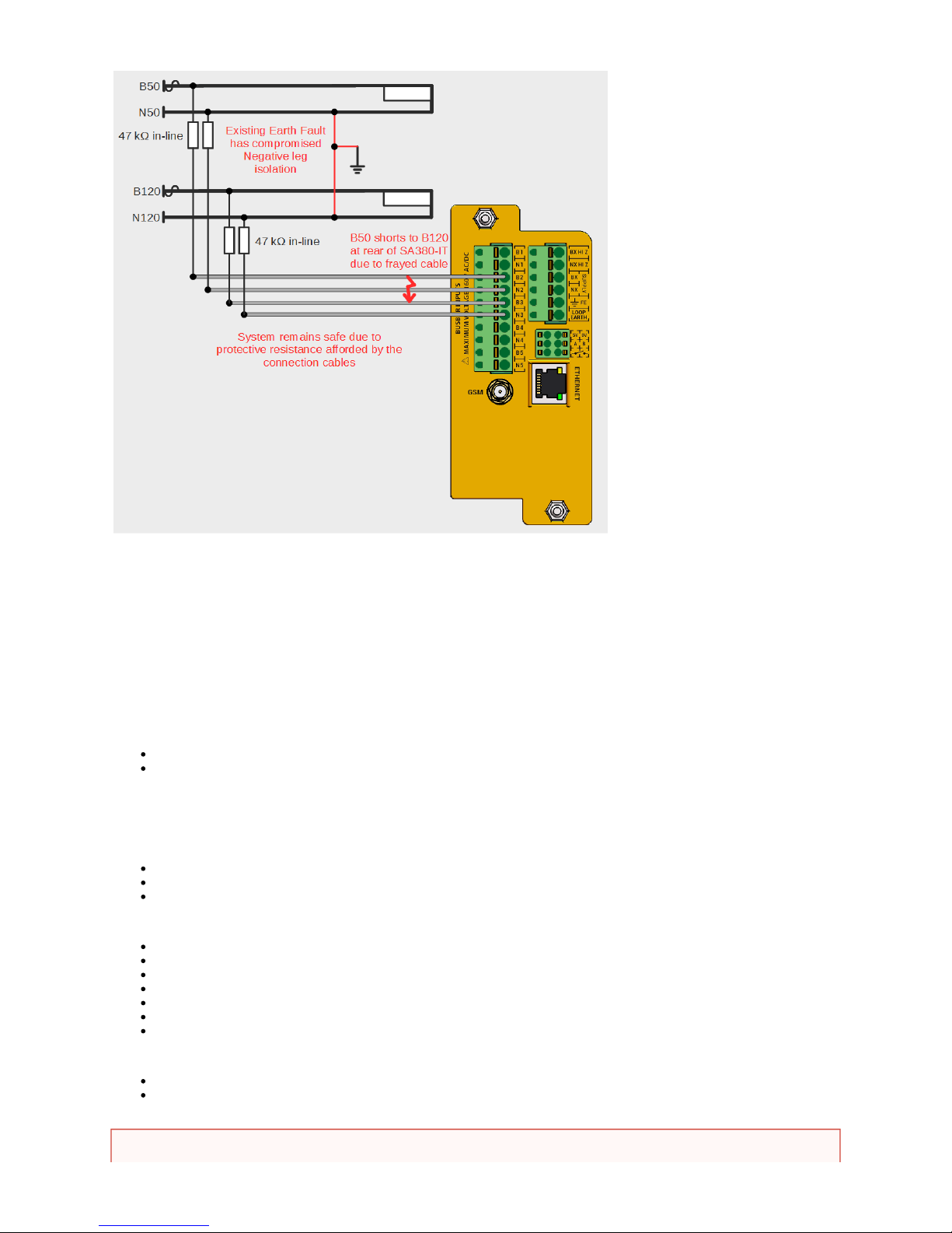
The preferred termination method is to situate the in-line resistor at the "monitored circuit end" of the termination to protect against cable
insulation fault, however this is at the discretion of the user.
If resistive cables are not fitted, incorrect readings will be obtained.
3.6.2 Via HI Z Outputs
It is common to perform monitored circuit functions on the same circuit that is used to power the SA380-IT device.
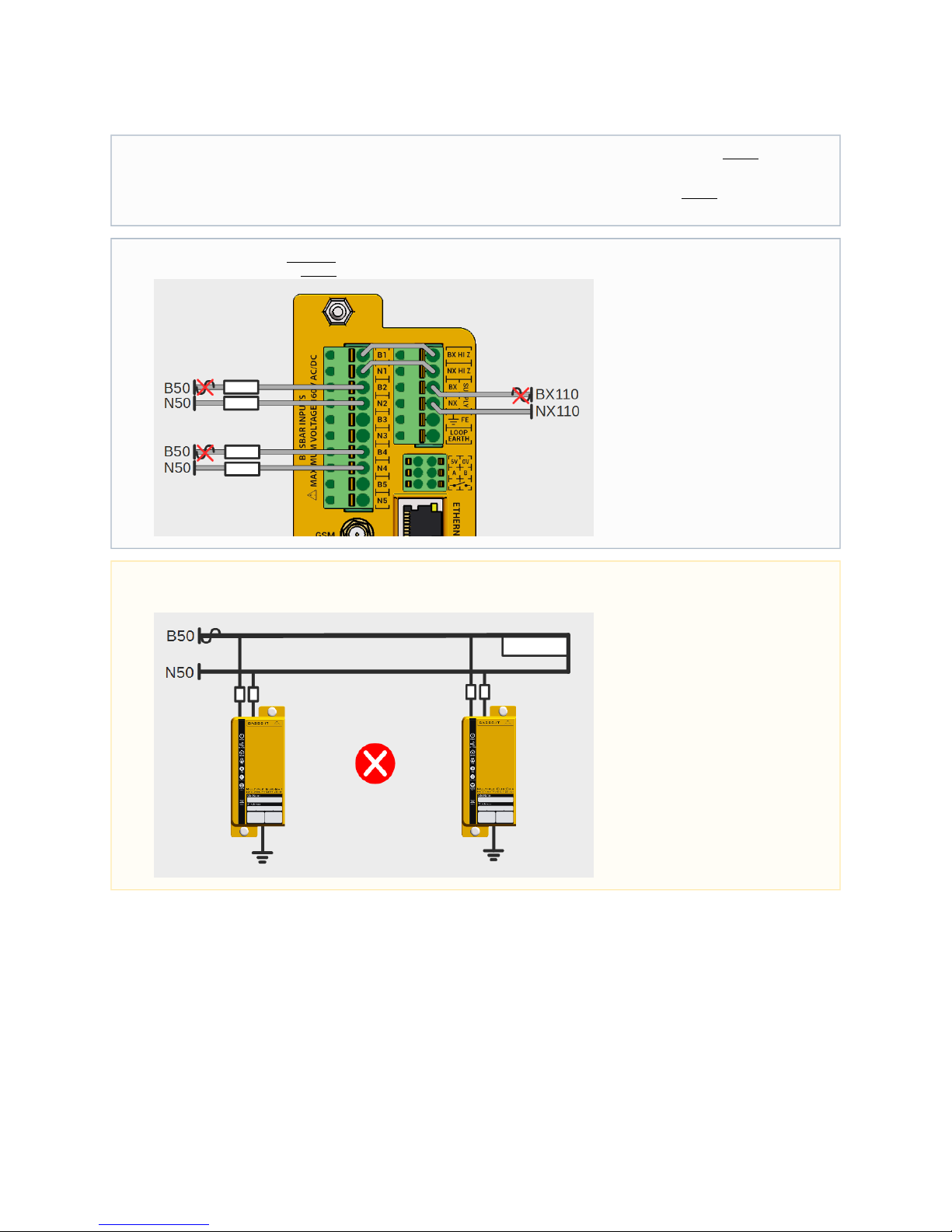
To simplify wiring it is possible to "jumper" across the power supply into "Channel 1" of the monitored circuits. This is achieved by the "HI Z"
outputs.
The "HI Z" outputs present the power supply voltage as an output, albeit with a 47 k resistor in each circuit leg. E.g.
BX HI Z is BX Supply with 47 k in series.
NX HI Z is NX Supply with 47 k in series.
This means that resistive cables are not required to jumper the HI Z outputs across to channel 1 as shown in the diagram below.
Network Rail users must use "Grey 0.75 mm A1" cable (supplied with the device) for these terminations.
Tools / Parts Required:
Ferrules
Crimp Tool
Resistive Cables (MPEC Part No. SA380-IT-RC)
Actions when using Resistive Cable:
Each monitored circuit can be AC or DC and range from 5 V to 160 V RMS.
Where possible, disconnect the voltage at the positive and negative termination point on the monitored circuits bus-bar.
Connect the end of the cable with the resistor fitted to the positive or "B leg" of the monitored circuit.
Connect the far end of the cable to the appropriate "B leg" connection at the rear of the SA380-IT.
Connect the end of the cable with the resistor fitted to the negative or "N leg" of the monitored circuit.
Connect the far end of the cable to the appropriate "N leg" connection at the rear of the SA380-IT.
The cables should be shortened at the SA380-IT end if possible.
Actions when using HiZ Outputs:
Connect "BX HI Z" to "B1" with standard cable (Do not use resistive cable).
Connect "NX HI Z" to "N1" with standard cable (Do not use resistive cable).
Never connect the SA380-IT directly to monitored circuits without:
Page 30
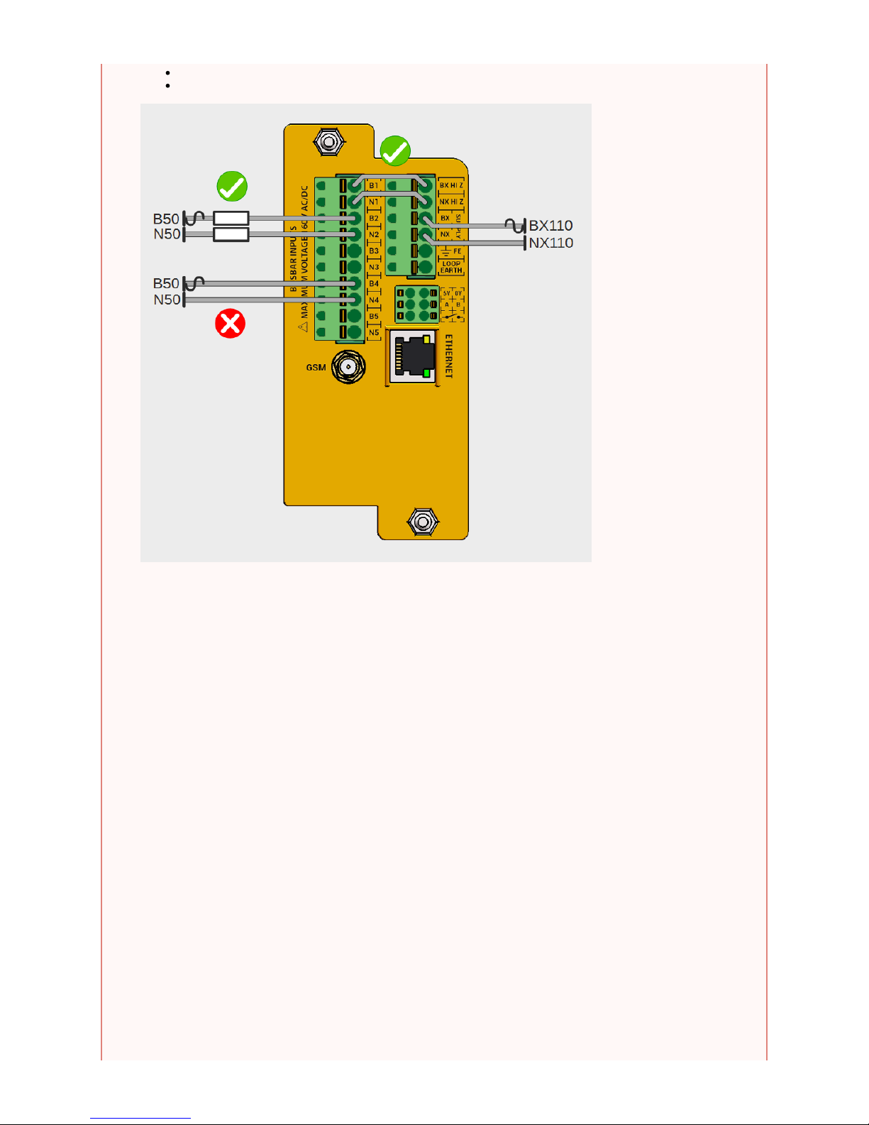
Using the approved resistive cable (MPEC part No. SA380-IT-RC).
Connecting via the BX HiZ and NX HiZ terminals.
Never attempt to "common together" any conductors from differing monitored circuits.
Never attempt to wire any conductors from differing monitored circuits into the same input channel.
Page 31
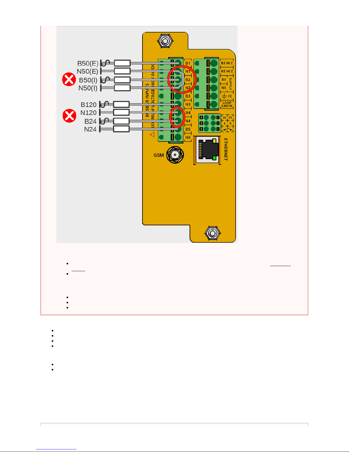
Tests when using Resistive Cable:
Test that the voltage of the monitored circuit is of the expected value and type (AC or DC).
Perform an earth test on the monitored circuit prior to commissioning.
Test the "B" wire end-to-end. The resistance must read 47 k +/-0.1 %. The spring-contact plug of the SA380-IT features a test-point.
Test the "N" wire end-to-end. The resistance must read 47 k +/-0.1 %. The spring-contact plug of the SA380-IT features a test-point.
Tests when using HI Z Outputs:
Continuity test "BX HI Z" to "B1". The spring-contact plug of the SA380-IT features a test-point.
Continuity test "NX HI Z" to "N1". The spring-contact plug of the SA380-IT features a test-point.
3.7) Connection of Peripheral Equipment
3.7.1 GSM
The SA380-IT device can be shipped with factory fitted SIM and GSM antenna.
Always check the voltage of the monitored and supply circuits:
Check each monitored or supply circuit does not exceed the specified maximum system voltage (160V RMS
)AC/DC
Ensure wiring of monitored or supply circuits is performed such that the cabling is not "live" until installation is
complete.
Attempting any of the above poses a risk of:
Circumvention if the inter-isolation of monitored circuits.
Short circuit of individual monitored circuits.
Electric shock.
Page 32
Tools / Parts Required:
Drill with appropriate 12 mm bit maybe required.
Actions:
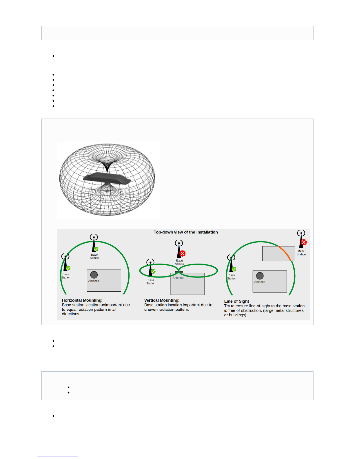
In railway settings the antenna must be fitted to the outside of the equipment enclosure (typically a location case or REB)
Affix the antenna head to the exterior of the equipment housing using the self-adhesive backing and back-nut. (Panel Mount)
This may require drilling a 12 mm hole.
For non-panel mount scenarios, additional brackets may be required. These are not supplied with the SA380-IT.
Affix the antenna tail cable using the SMA screw-fit connector to the rear of the logger - do not over tighten.
Do not attempt to shorten the cable without appropriate specialist tools.
Do not force the antenna cable around tight bends.
Test:
The GSM connection status of the logger can be casually observed using the SA380-IT status indications. (See section 4.2)
In-depth status information can be observed using the web-based configuration and diagnostics application (see section 4.4.4)
3.7.2 Ethernet
Tools / Parts Required:
None
Actions:
Please liaise with MPEC to specify your desired SIM package
Antenna placement tips
The radiation pattern of the supplied antenna is a torus (doughnut) about the horizontal plane.
There is zero reception directly above or below the antenna, there is maximal and even reception around the horizontal plane.
The Ethernet is sensitive to electrical surges:
Additional surge protection be fitted if the port is to be used in a continuously. must
Surge protection is not required for temporary configuration and diagnostics activities.
Page 33
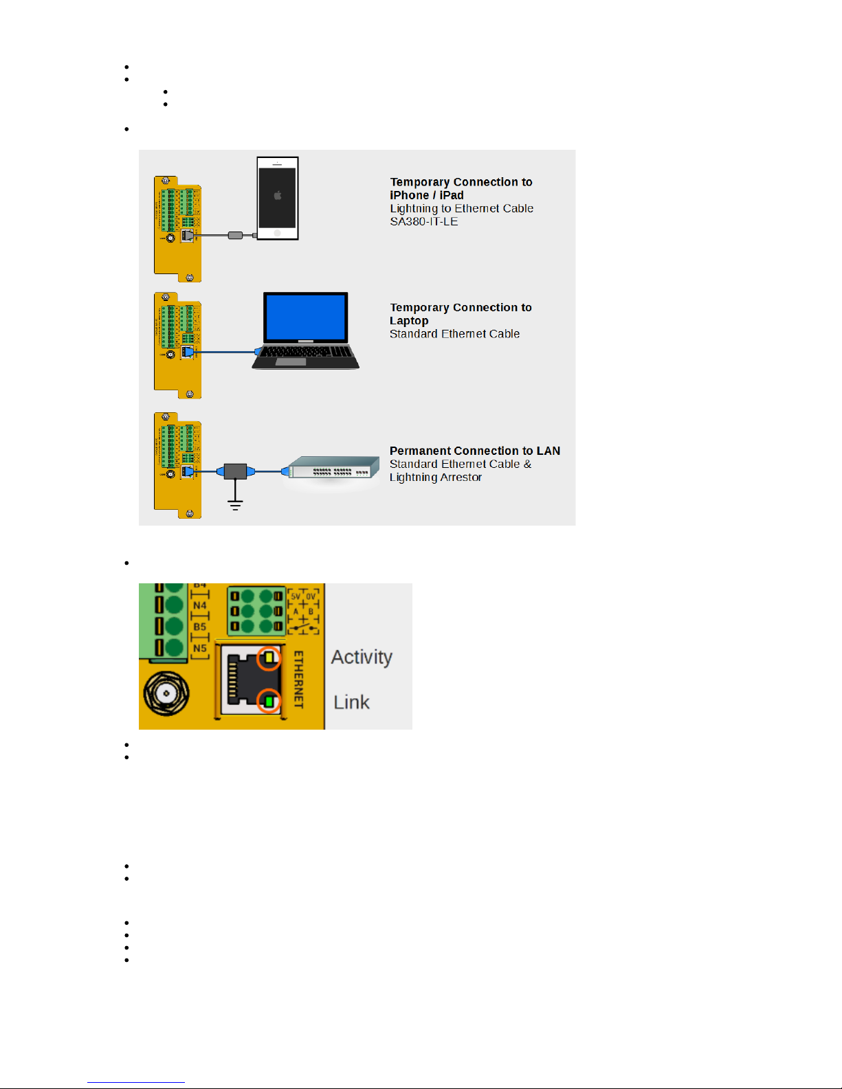
The Ethernet port accepts standard Ethernet cable via an RJ45 connector.
The Ethernet port can be used as a monitoring port with no additional protection required.
If connecting direct to a computer, simply use an Ethernet patch cable to connect devices point to point.
If connecting to an Apple iPad of iPhone you must use the MPEC "Lightning to Ethernet" cable (MPEC Part No.
SA380-IT-LE) and have the SA380-IT "App" installation (available on the App-store).
If using the Ethernet port as a permanent data connection then an additional lightning arrestor device rated to 2 kV line-to-earth must
be provided between SA380-IT and local switch.
Test
Successful connection can be verified by checking that the LAN port Link indication is lit solid, and the the activity indication is
blinking.
The connection status of the logger can be casually observed using the SA380-IT status indications. (See section 4.2)
In-depth status information can be observed using the web-based configuration and diagnostics application. (see section 4.4.4)
3.7.3 Volt-Free Contact (VFC)
The VFC is used to give a local indication of hardware or earth fault.
Tools / Parts Required:
Ferrules.
Crimp Tool.
Action:
The VFC acts as a simple switch, the polarity of connection is irrelevant.
The maximum voltage that can be applied across the VFC is 60 V DC or 60 V AC RMS.
The minimum loop impedance of the circuit must be 100 in order to meet line-to-line surge immunity requirements.
The VFC is to be wired into an alarm circuit, or VFC input of a data logging device as follows:
Page 34
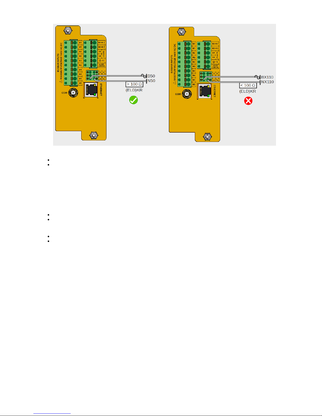
Test:
With the logger un-powered - test that the resistance between VFC ports is > 1 M.
With the logger powered and fault-free - test that the resistance between VFC ports is < 8.
3.7.4 Auxiliary Power Output
A 5 V DC, 1 W regulated power supply is made available at the rear of the unit to power auxiliary sensors.
The output is short-circuit and overload protected.
Tools / Parts Required:
Ferrules
Crimp Tool
Action:
Connect the SA380-IT 5 V terminal to the positive power terminal of the auxiliary equipment.
Connect the SA380-IT 0 V terminal to the negative power terminal of the auxiliary equipment.
Page 35
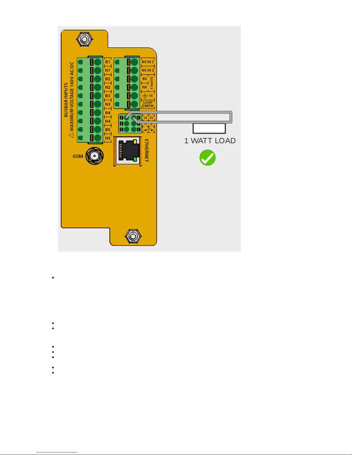
Test
With the logger powered, check for 5 V DC across the output terminals.
3.7.5 RS485
The RS485 link is provided to allow data connection to auxiliary sensors and data logging equipment.
Tools / Parts Required:
Ferrules.
Crimp Tool.
Action:
Wire the RS485 link using twisted pair cable.
For wiring runs over 10 meters consider using screened cable is interference maybe experienced.
For wiring runs over 30 meters, 100 line-termination resistors should be fitted across the "A,B" terminations at both extremities of
the data link.
Wire "A" to "A" and "B" to "B" on all devices
RS485 supports a multi-drop bus architecture, numerous devices can share the same RS485 bus.
.
Page 36
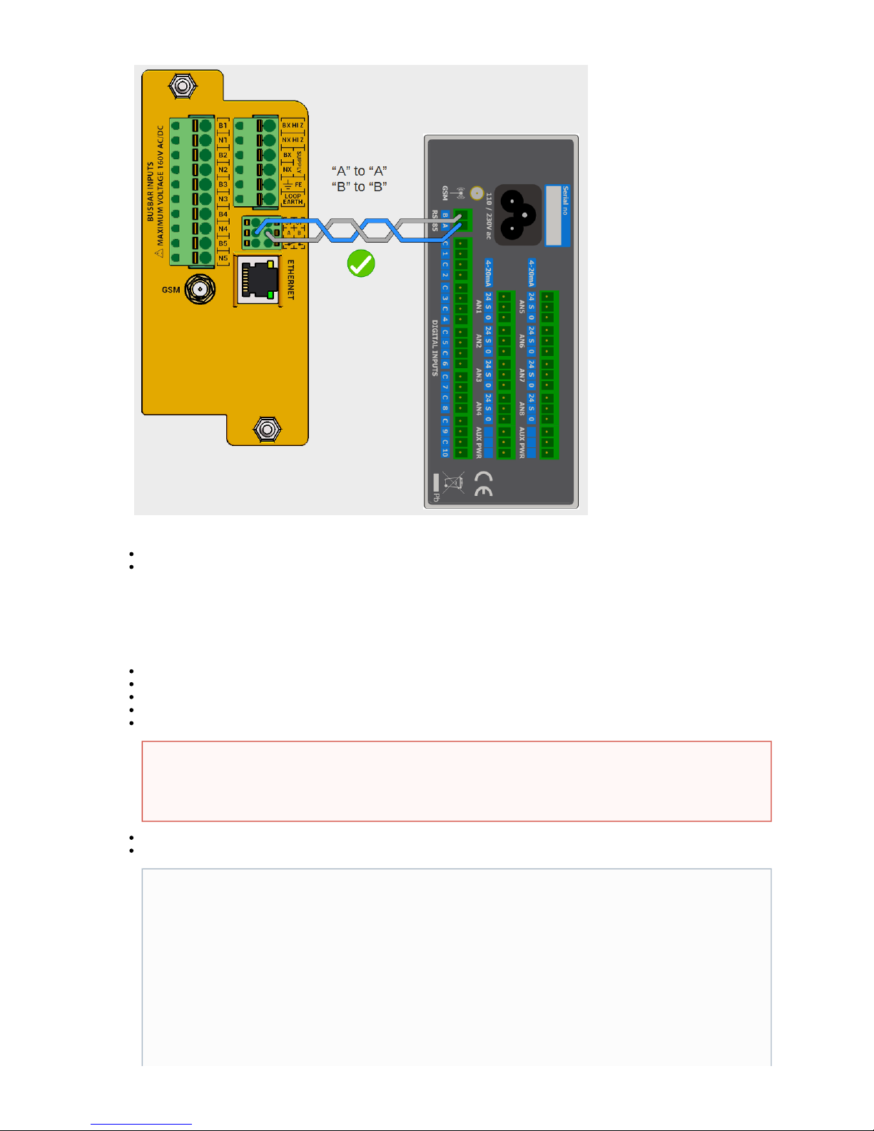
Test:
With an RS485 device configured, the RS485 indication will light steadily to indicate a valid data session.
A flashing RS485 indication indicates that devices are configured to converse, but are unable to do so.
3.8) Commissioning
The following steps are recommended to commission the SA380-IT into service:
Test all wiring for continuity.
Visually inspect all wiring for sound installation.
Measure voltages of supply and monitored circuits an confirm they are within specification.
Connect fuses and/or links of circuits.monitored
Perform a manual earth test of all circuits.monitored
Apply main power to the SA380-IT.
Connect to the SA380-IT using the web based tool (see section 4.3)
The results of earth testing after installation should be the same as prior to installation.
If the results of earth testing are worse, then the SA380-IT maybe damaged.
Remove the device from service immediately and return to MPEC for investigation.
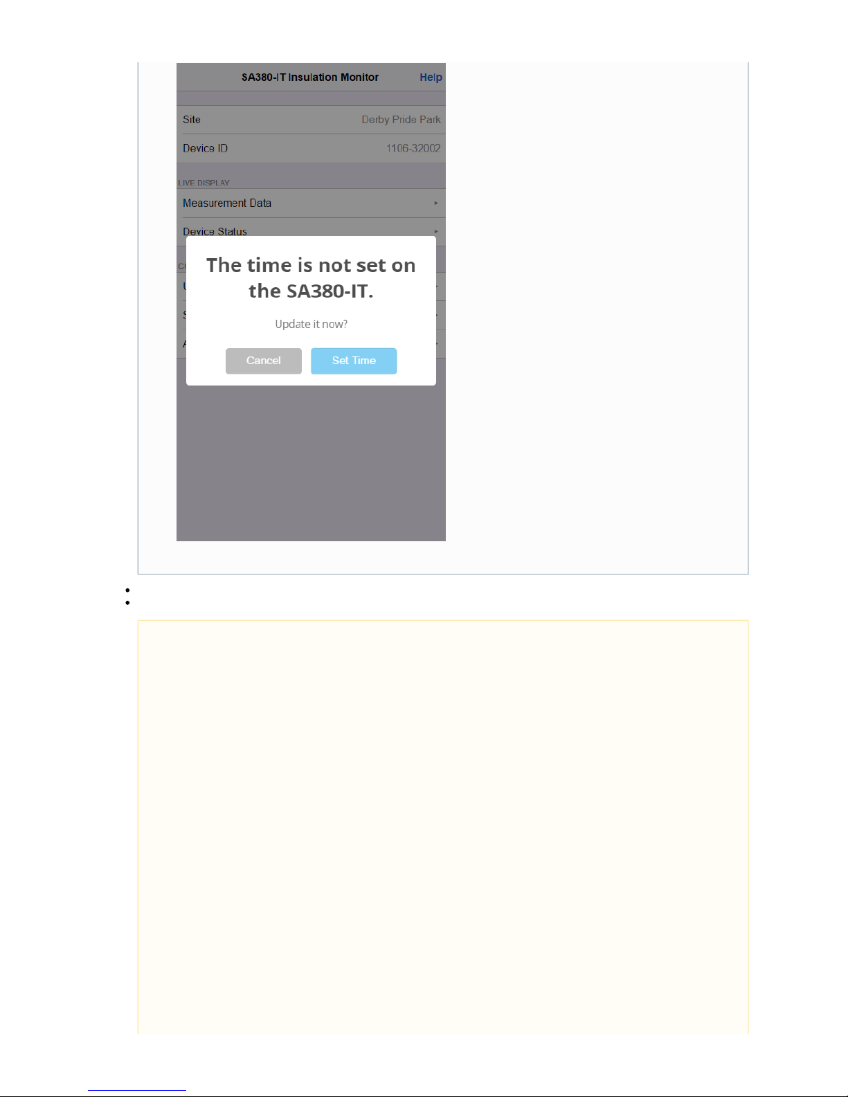
You may need to set the time on the device if the SA380-IT is unable to locate a time-server using the GSM or Ethernet
connections
Page 37
Perform monitored circuits setup (see section 4.4.8 and 4.4.9).
Check alert levels meet your requirements.
The SA380-IT will not perform any measurements if the time is not set.
Please check that the factory set earth loop and insulation resistance alarm levels are correct for your application. (See
section 4.4.10)
Page 38
Check that the device can connect to the Enterprise Asset Management System (See section 4.4.4).
4) Operation
This section details the meaning of the front panel indications and the operation of the web-based interrogation and configuration tool.
4.2) SA380-IT Front Panel Indications
Indication Colour Steady On Steady Off Pulsate Fault Finding
Actions
Green
Power applied to
SA380-IT.
SA380-IT unpowered
or faulty.
NA Device faulty if power
applied and unlit.
Green
The modem is
registered and
attached to the GPRS
network.
GPRS Network
unavailable or device
configured to use
Ethernet.
NA Check network
connection and
network settings if
unlit.
Green
A data session is in
progress with an
enterprise asset
management system.
The asset
management system is
unavailable and the
device is in fall-back.
NA Check live device
status and network
server settings.
Green
Self-test in progress. Self-test not in
progress.
NA Device faulty if in
normal mode and this
does not light once
every 30 seconds.
Page 39
Green
Software failure. Software failure. Normal Operation. Restart device if
steady on or steady
off. Remove from
service if fault persists.
Red
Safety Interlocks have
detected a device fault,
or earth loop
resistance is above
alert threshold.
No hardware fault,
earth loop resistance
within tolerable range.
NA See section 5. (Fault
Finding) if lit.
Red
One or more of the
monitored circuits is
presently thebelow
configured alert
threshold.
All monitored circuits
are presently safely ab
the configuredove
alert threshold.
NA Remedial action
required to monitored
circuits if lit.
Green
A data session is in
progress with another
device on the serial
port
No data connection is
configured for the
serial port
A data connection has
been configured,
however the device is
unable to converse.
Check serial
connection, live status
and serial settings if
pulsating.
The volt-free contact output will be open when either or are lit.HW FAULT EARTH FAULT
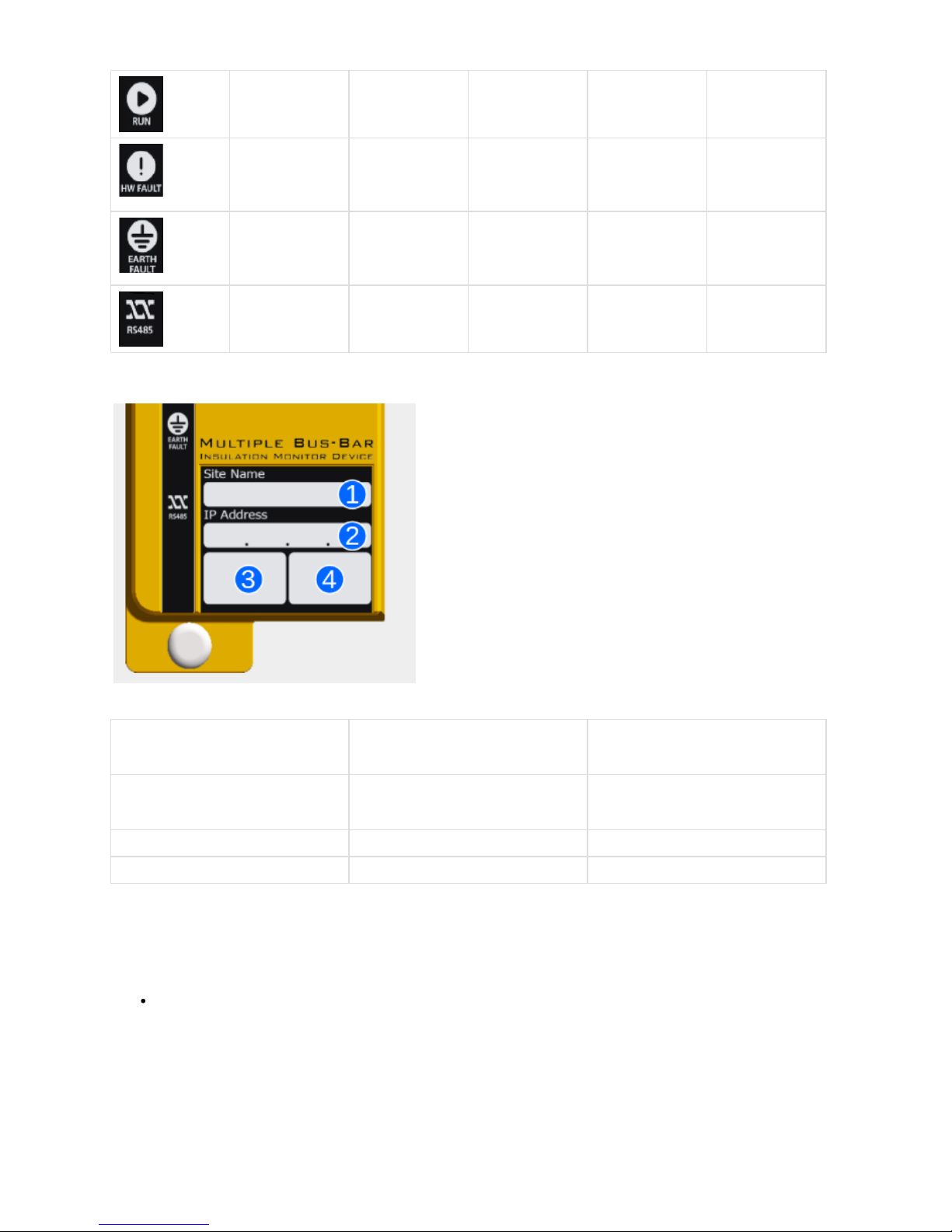
The label on the front of the SA380-IT is for recording useful information about the product:
1 Site Name
Write the unique name of the device here
such that it matches that of the device
configuration.
2 IP Address Write the devices IP address Ethernet
here. This is to ease on-site connection via
an Apple iDevice or Computer.
3 SIM Serial No.
Fitted at factory.
4 SA380-IT Serial No.
Assigned at factory.
4.3) Connecting the SA380-IT with a Computer or Apple device
4.3.1 Connect to a Computer directly using an Ethernet Cable
Connect Ethernet Cable.
Page 40
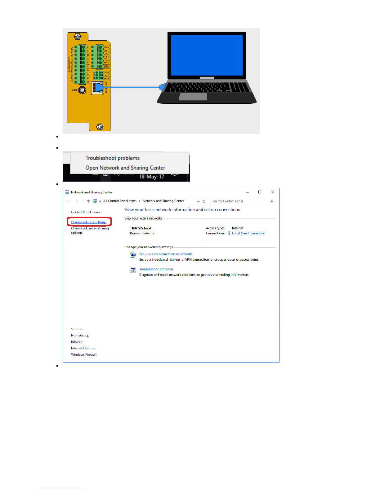
The following instruction apply to the "Windows 10" operating system, however the network settings will be the same regardless of
operating system.
Open Networks & Sharing Center:
Change Adapter Settings:
On "Local Area Connection", right-click, select "Properties":
Page 41
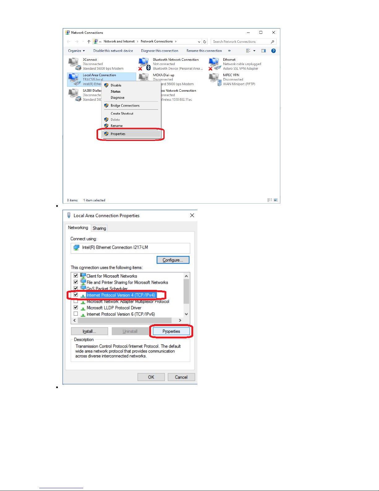
Select "Internet Protocol Version 4 (TCP/IPv4)", then click "Properties":
Use the following IP settings, then click OK:
Page 42
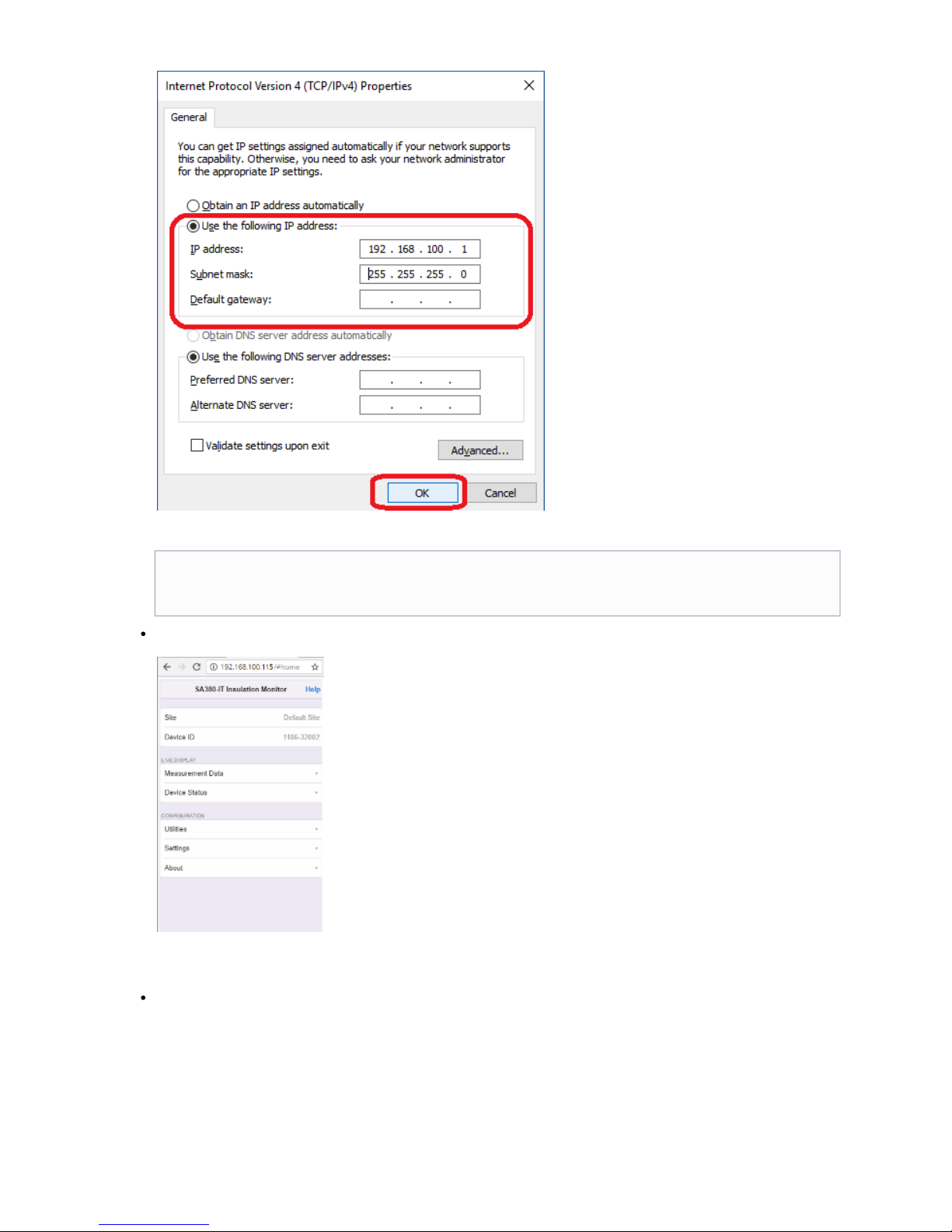
Connect to the web-based configuration and diagnostics tool using any HTML 5 compatible web browser. Use the IP address
displayed on the front of the device. The default IP address is 192.168.100.115.
4.3.2 Connect to an Apple Device directly using a Lightning to Ethernet Cable
Connect the Lightning to Ethernet Cable (MPEC part no. SA380-IT-LE)
These settings assume that the SA380-IT resides on the 192.168.100.xxx sub-net. This is the default setting. If the IP
address of your SA380-IT has been changed, it should be recorded on the front panel of the device (see 4.2). You may
need to change the IP address in the above dialogue box to match the sub-net of your SA380-IT.
Page 43
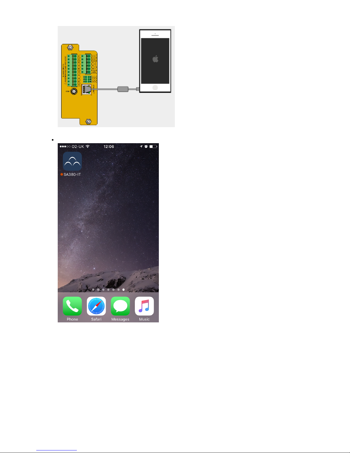
Open the App
Page 44
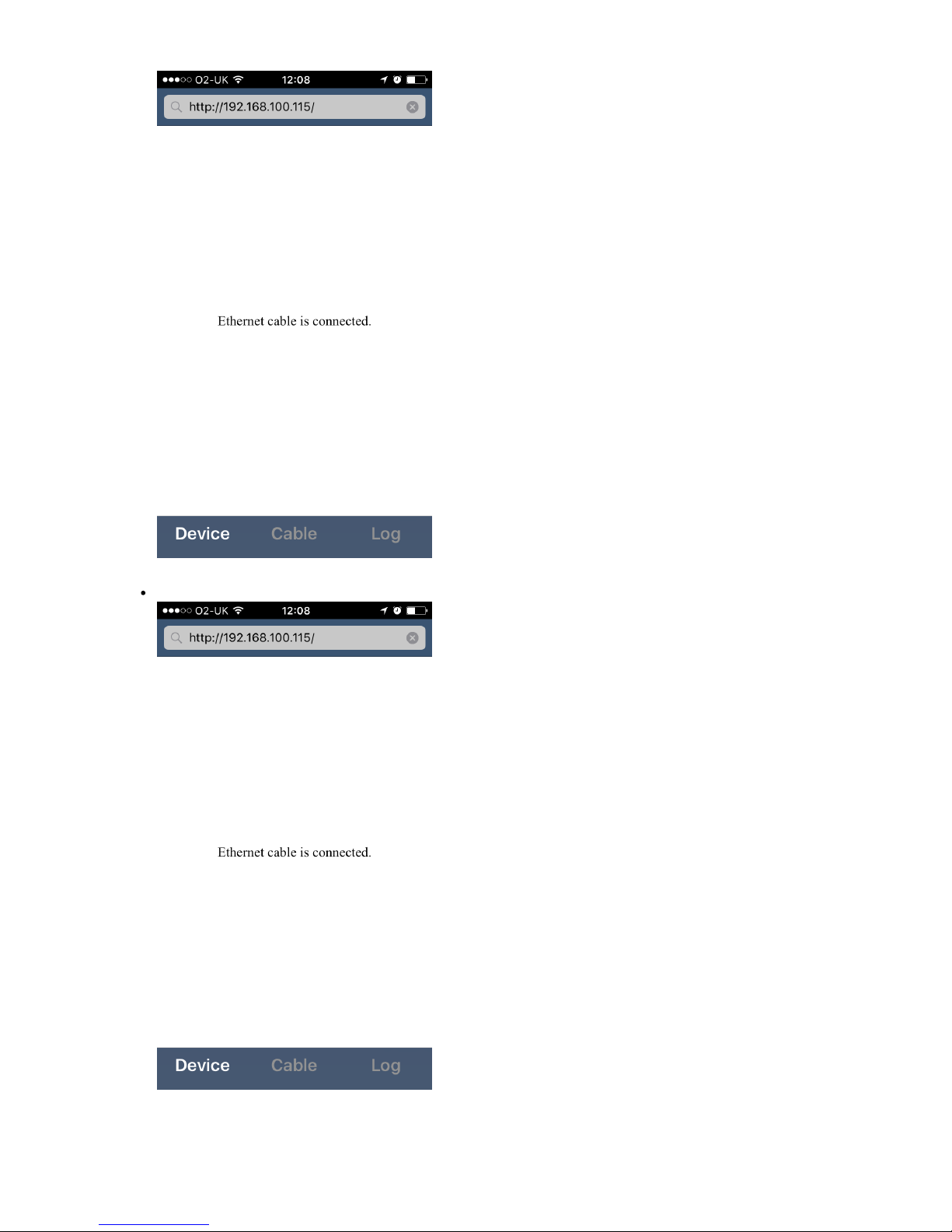
If your IP is 192.168.100.115 the the web-based configuration and diagnostics tool will load automatically:
Page 45
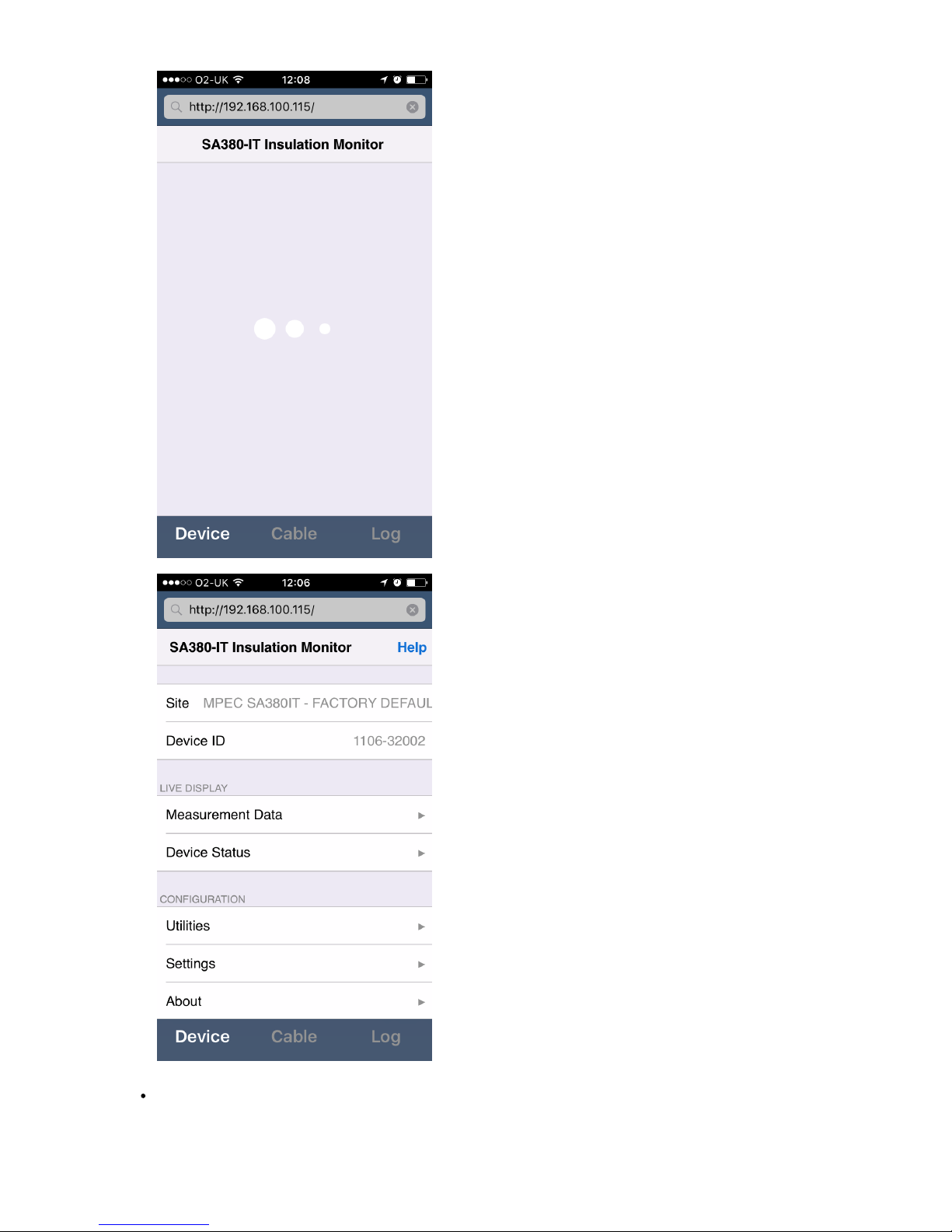
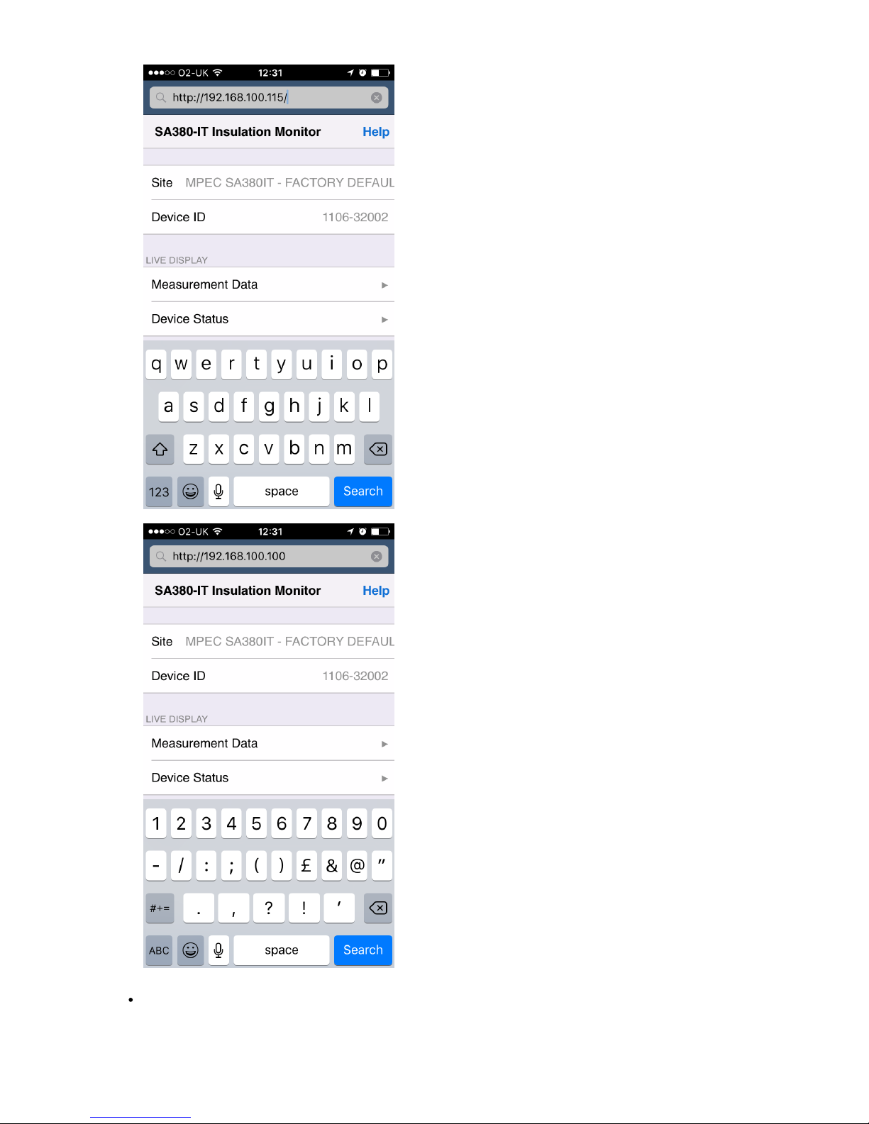
If the SA380-IT IP address differs from that above, tap the address bar and enter IP address of the SA380-IT as recorded on the
front of the device:
Page 46
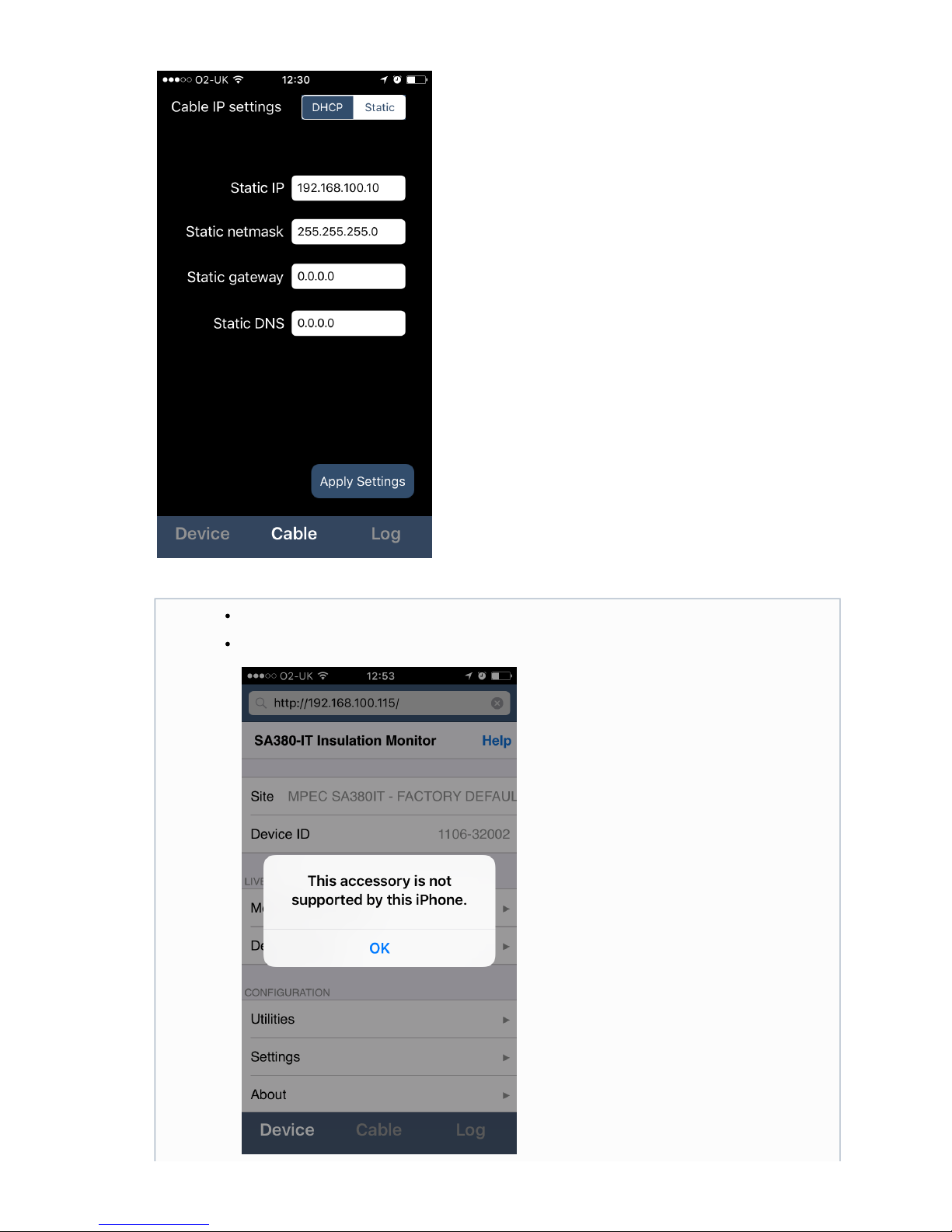
If the SA380-IT sits outside the 192.168.100.xxx sub-net, then the network settings of the App need to match those of the SA380-IT
device. These can be altered by tapping the "Cable" button. Follow the advice in section 4.3.1.
Page 47
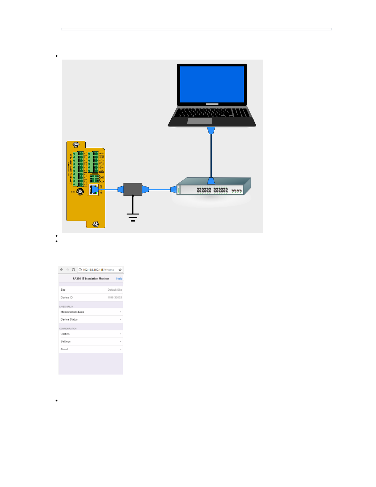
Intermittent cable connection may make cause your the iOS device to be unable to recognize the Lightning to
Ethernet cable any more:
Should this happen you need to restart the iOS device and start the application again.
Page 48
4.4.4 Connect via a Local Area Network using Ethernet
You may connect to an SA380-IT over a local network (LAN):
When connected via Ethernet, your computer may receive an IP address automatically via DHCP.
If IP address are assigned statically, you will need to configure your computers IP address to that of the local network as in "Connect
to a Computer directly using an Ethernet Cable". (4.3.1)
Once your computer is connected to the same LAN as the SA380-IT, enter the static IP of the SA380-IT device, (as written on the
front panel), into any HTML 5 compatible web browser:
4.4.5 Connect via GSM Network
Connection to an SA380-IT is only possible if the GSM provider has assigned the SA380-IT with a fixed IP. This can typically be
achieved through provision of a private APN, or VPN.
Page 49
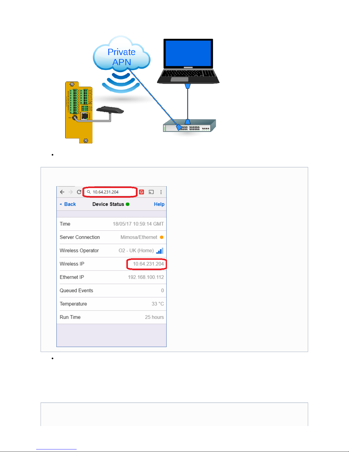
If your SA380-IT has a rout-able IP address, then simply enter the into the web-browser of a computer that sits on theWireless IP
same network.
Configuration of private APNs and VPNs is beyond the scope of this user guide.
4.4) Navigating the SA380-IT User Interface
4.4.1 Main Menu
The is provided by the GSM operator. It is not to be confused with the displayed on the front of theWireless IP Ethernet IP
SA380-IT.
You may need to set the time on the device if the SA380-IT is unable to locate a time-server using the GSM or Ethernet
connections.
Page 50
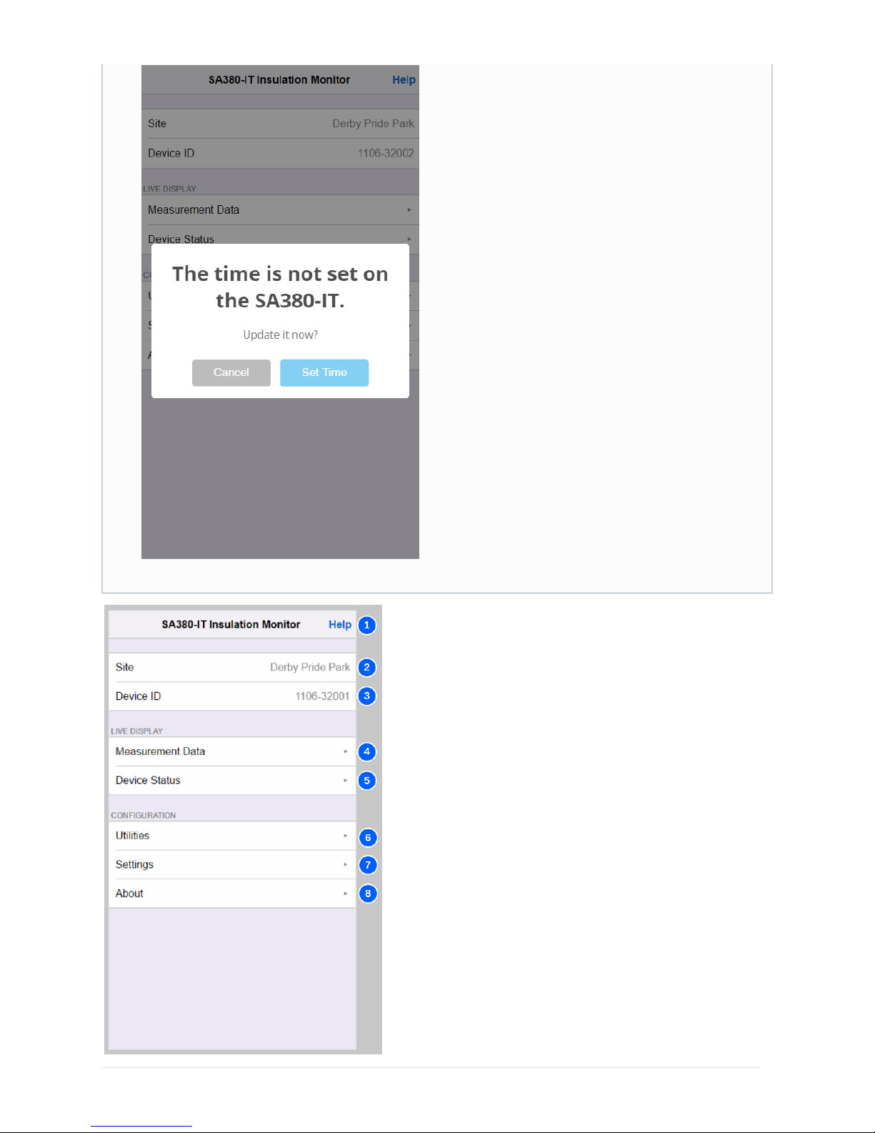
The SA380-IT will not perform any measurements if the time is not set.
Page 51
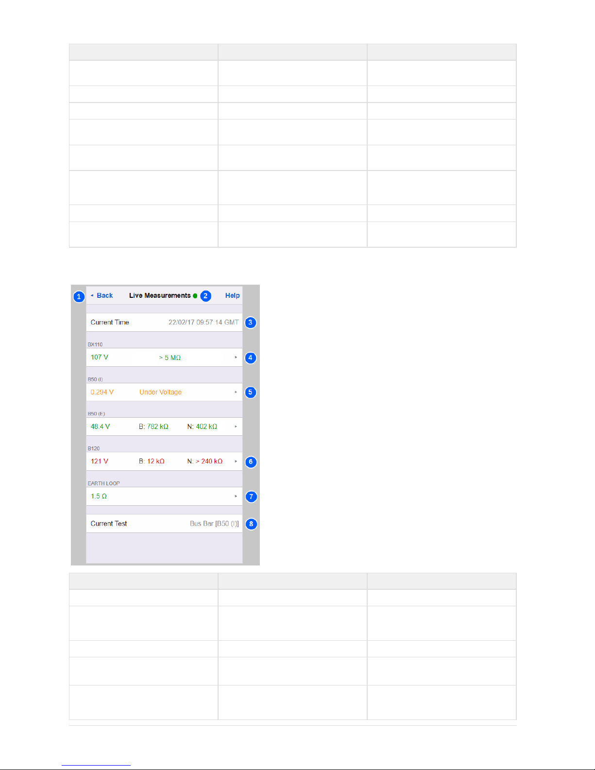
No. Name Description
1 Help
Each page features a help link to this user
guide.
2 Site
The name of the installation.
3 Device ID
The unique ID of the device.
4 Measurement Data
Click here to access live measurement
readings of monitored circuits.
5 Device Status
Click here to access live connectivity and
device health information.
6 Utilities
Click here to access engineering functions
such as device and communications reset,
time update and firmware upgrade.
7 Settings
Click here to access all device settings.
8 About
Click here to view hardware and software
build information.
4.4.2 Live Measurements
No. Name Description
1 Back
Navigates back to the main menu.
2 Connection Status
A green dot indicates a live connection to
the device. A red dot denotes that the
connection has been lost.
3 Time
The current time set on the device.
4 AC Monitored Circuit
AC monitored circuits show circuit voltage
and equivalent resistance to earth (R ).
L
5 Locked Monitored Circuit This circuit is suffering from an under-volt
hence no resistance to earth readingage
has been taken.
Page 52
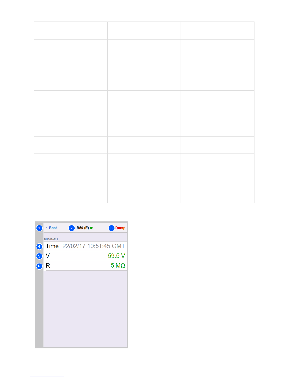
6 DC Monitored Circuit
DC monitored circuits show circuit voltage
and equivalent resistance to earth of each
circuit leg (RB and RN).
7 Earth Loop Resistance
The resistance between FE and Loop Earth
terminals.
8 Current Test
Displays the test currently being performed
by the device at the moment the page
refreshed.
Technicians Mode
Clicking on the white region of a monitored
circuit or earth loop display will cause the
device to enter for thatTechnicians Mode
particular circuit.
Missing Circuits
Only monitored circuits configured for
measurement are displayed.
Green Text
..is used to denote monitored circuits where
resistance to earth is the defined above
alert thresholds.
..is used to denote that earth loop
resistance is the defined alert below
threshold.
Orange Text
..is used to denote monitored circuits
suffering from a recoverable device
interlock.
Red Text
..is used to denote monitored circuits where
resistance to earth is the definedbelow
alert thresholds.
..is used to denote that earth loop
resistance is above the defined alert
threshold.
..is used to denote monitored circuits
suffering from an unrecoverable device
interlock.
4.4.3 Technicians Modes
Page 53

No. Name Description
1 Back
Navigates back to the live measurements
screen and terminates .technicians mode
2 Circuit Name & Connection Status
The name of the monitored circuit. A green
dot indicates a live connection to the
device. A red dot denotes that the
connection has been lost.
The physical input of the device to which
this monitored circuit is connected is shown
below.
3 Dump
Displays a detailed diagnostic data dump
(for manufacturers use).
4 Time
The current time.
5 Voltage
The monitored circuits present voltage. Not
displayed if earth loop resistance has been
selected.
6 Resistance
AC monitored circuits show equivalent
resistance to earth (RL).
DC monitored circuits show equivalent
resistance to earth of each circuit leg (R a
B
nd R ).
N
The Earth Loop circuit shows the present
resistance between FE and Loop Earth
terminals.
Technicians Mode
Whilst in technicians mode, only the
selected circuit is measured. This improves
response time for the circuit of interest to
aid faulting activities.
No other monitored circuit is measured,
earth loop resistance is not measured
(unless selected), device integrity checks
are not performed.
If the user should forget to leave
technicians mode, willnormal mode
automatically resume after a period of 4
hours.
Green Text
..is used to denote monitored circuits where
resistance to earth is the defined above
alert thresholds.
..is used to denote that earth loop
resistance is the defined alert below
threshold.
Orange Text
..is used to denote that the monitored
circuit is suffering from a recoverable
device interlock.
The user should manually exit
technicians mode when it is no
longer required such that
other measurements
recommence.
Page 54
Red Text
..is used to denote monitored circuits where
resistance to earth is the definedbelow
alert thresholds.
..is used to denote that earth loop
resistance is the defined alert above
threshold.
..is used to denote monitored circuits
suffering from an unrecoverable device
interlock.
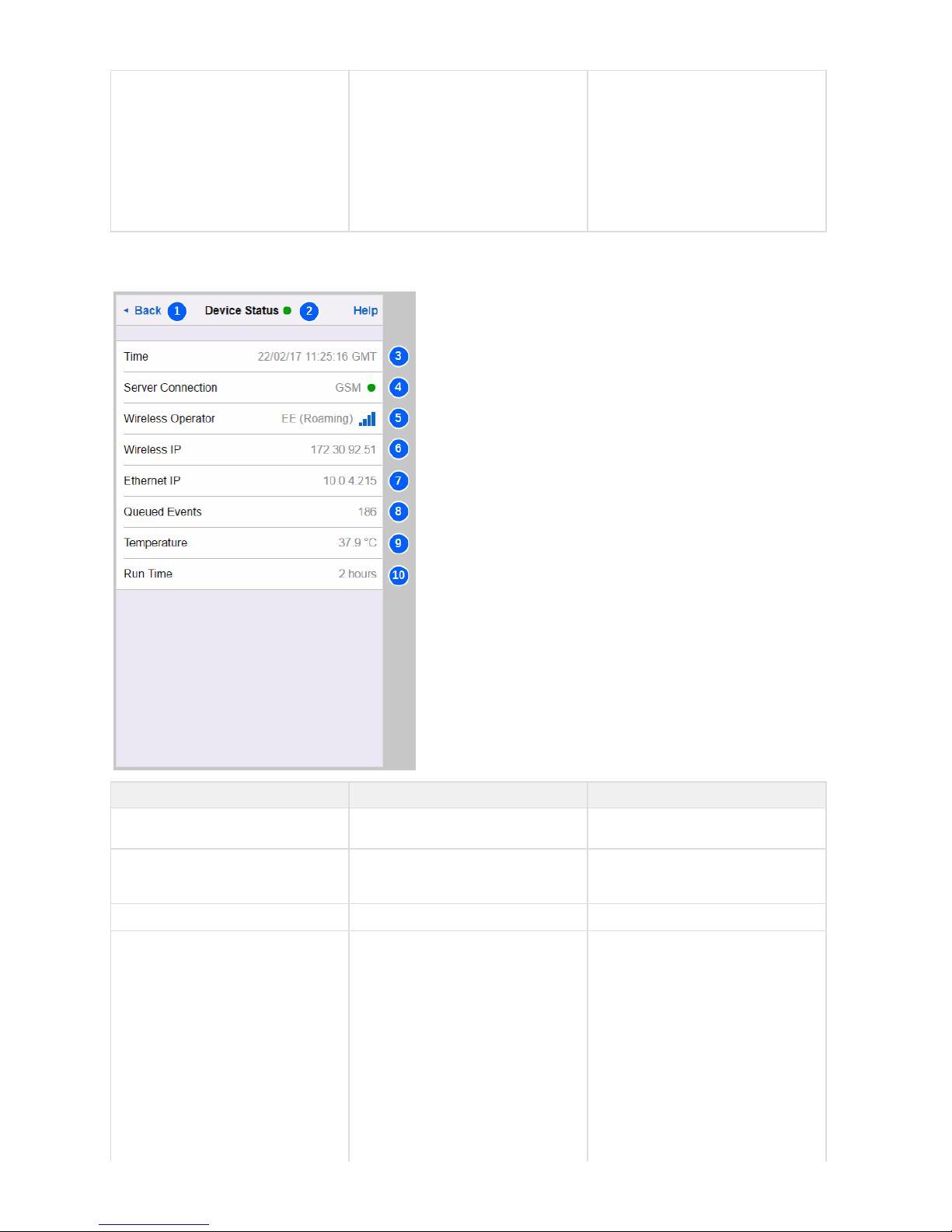
4.4.4 Device Status
No. Name Description
1 Back
Navigates back to the live measurements
screen.
2 Connection Status
A green dot indicates a live connection to
the device. A red dot denotes that the
connection has been lost.
3 Time
The current time.
4 Server Connection
Shows if the server connection is presently
using or as aGSM Ethernet
communications bearer.
Upon power-up, the SA380-IT will attempt
to connect over GSM. If this fails, or if GSM
is not configured, the device will attempt to
connect over Ethernet.
If the connection attempt over Ethernet is
unsuccessful, or Ethernet is not configured,
the device will re-attempt to connect over
GSM, and the cycle repeats.
Page 55

The coloured circle denotes the present
state of the Enterprise Asset Management
System (EAMS) server connection:
Black
EAMS Server
connection is not
initialised - please
wait.
Red
...when connection
is first established:
The EAMS server
has yet to be
contacted.
...after which: The
EAMS server can
not be reached.
If using the
MIMOSA protocol,
the device can
reside in a
prolonged
"back-off" state for
up to 4 hours.
During this period
the SA380-IT will
not attempt
re-connection.
If connection
remains "red" for
more than 10
minutes in the
case of the MPEC
RailDAQ protocol,
or 4 hours in the
case of the
MIMOSA protocol,
refer to the
troubleshooting
steps below.
Orange
Indicates that
"handshaking"
events have taken
place with the
EAMS server, but
no data has been
sent.
If the connection
remains "orange"
for more than 2
minutes, refer to
the
troubleshooting
steps below.
Green
The SA380-IT is
connected to the
EAMS server side
system and data is
being successfully
transmitted.
Page 56
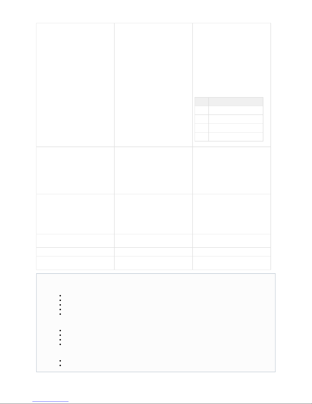
5 Wireless Operator
Displays the connection state of the
modem:
Blank: Modem not configured.
Waiting for Modem: The SA380-IT is
waiting for the modem to power-up.
Searching: The modem is searching for an
operator.
Operator Name: When registered with an
operator, the operator name, and GSM
signal strength is displayed.
Signal Strength:
Bars Meaning
1
Poor - Requires improvement
2
OK - May struggle at times
3
Good - No action required
4
Excellent - No action required
6 Wireless IP
The IP address obtained by the modem for
the GPRS data session:
Blank: GSM modem off or not registered
with a carrier.
0.0.0.0: Unable to create a GPRS session.
Valid IP Address: GPRS session
successfully established.
7 Ethernet IP
The SA380-IT does not support DHCP, and
can therefore not request an IP from
another device.
The Ethernet IP address is "static" and
assigned by the user through configuration.
It is the configured IP address that is
displayed here.
8 Queued Events
How many data events are awaiting
transmission to the server.
9 Temperature
Internal temperature of the SA380-IT.
10 Run Time
How long the SA380-IT has continuously
operating since last reboot.
Connection Troubleshooting:
For a GSM connection:
Check the correct configuration for the SIM. (APN, Username, Password)
Check that GSM signal strength is sufficient. (2 or more bars)
Check that the modem has registered. (operator name displayed)
Check that a GPRS session is active. (Wireless IP Address obtained)
Check that the SIM is activated, with the correct APN enabled. (with carrier)
For an Ethernet connection:
Check that the Ethernet settings are correct. (IP address, subnet, gateway and DNS entries)
Check that GSM has been disabled. (APN is blank)
Check wiring.
Check "upstream" routing equipment and settings.
In both instances:
Check that the server settings are correct. (Correct URL and protocol)
Check that the server is contactable. (with company IT support)
Page 57
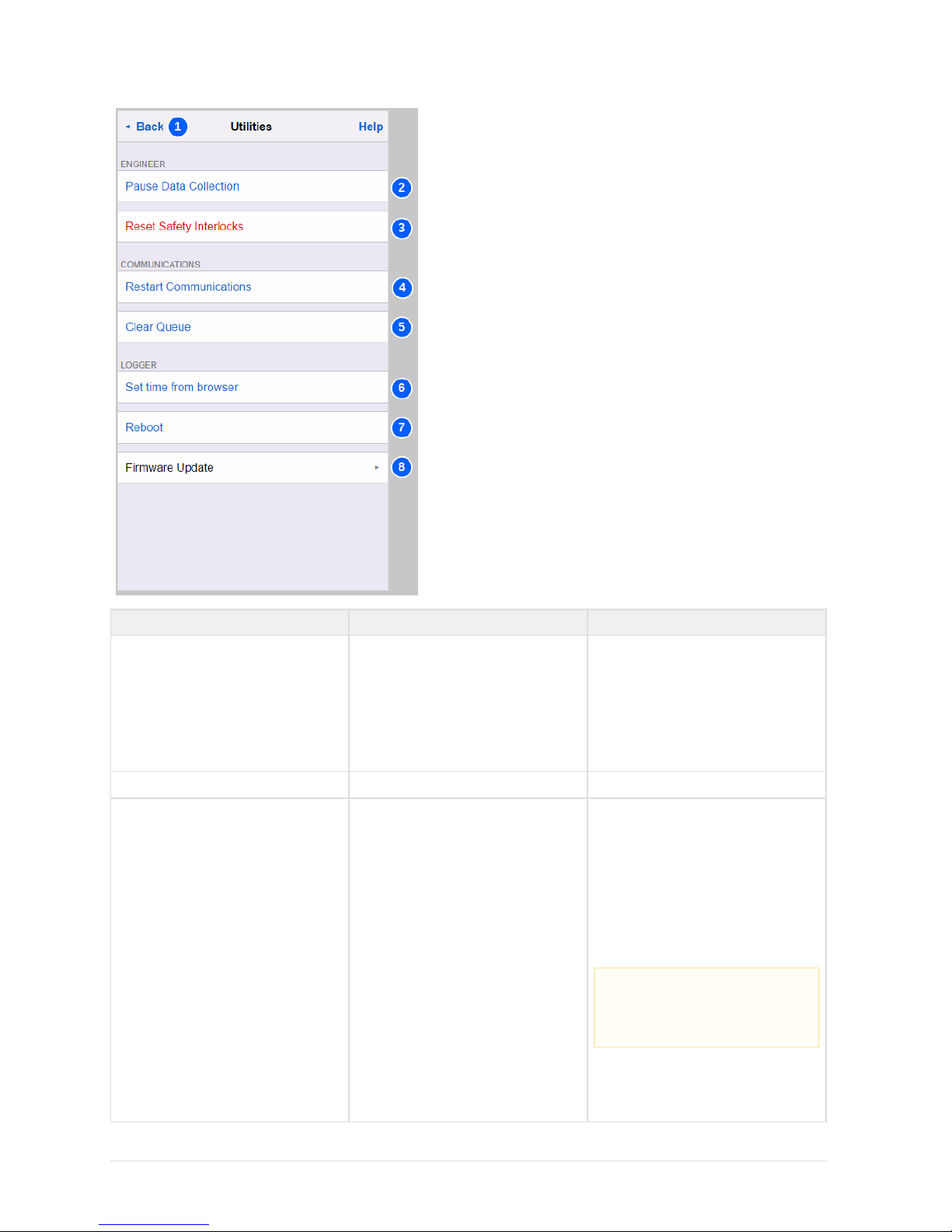
4.4.5 Utilities
No. Name Description
Authentication All items on this screen change the
behaviour of the SA380-IT.
Authentication (username and
password) are required to carry-out
these actions.
Please contact MPEC or your line
manager to obtain the correct
credentials.
1 Back
Navigates back to the main menu.
2 Pause Data Collection /
Resume Data Collection
This toggles the SA380-IT between suspe
and (seended mode normal mode
section 2.3).
The SA380-IT will not attempt any
measurement during suspended mode, nor
connect any monitored circuit to the
measurement circuitry or earth. This is to
allow fault finding activities to take place on
the connected circuits without having to
physically disconnect the device.
If the user should forget to terminate
suspended mode mode, normal mode will
automatically resume after a period of 4
hours.
The user should manually exit
suspended mode when it is no
longer required such that
measurements recommence.
Page 58
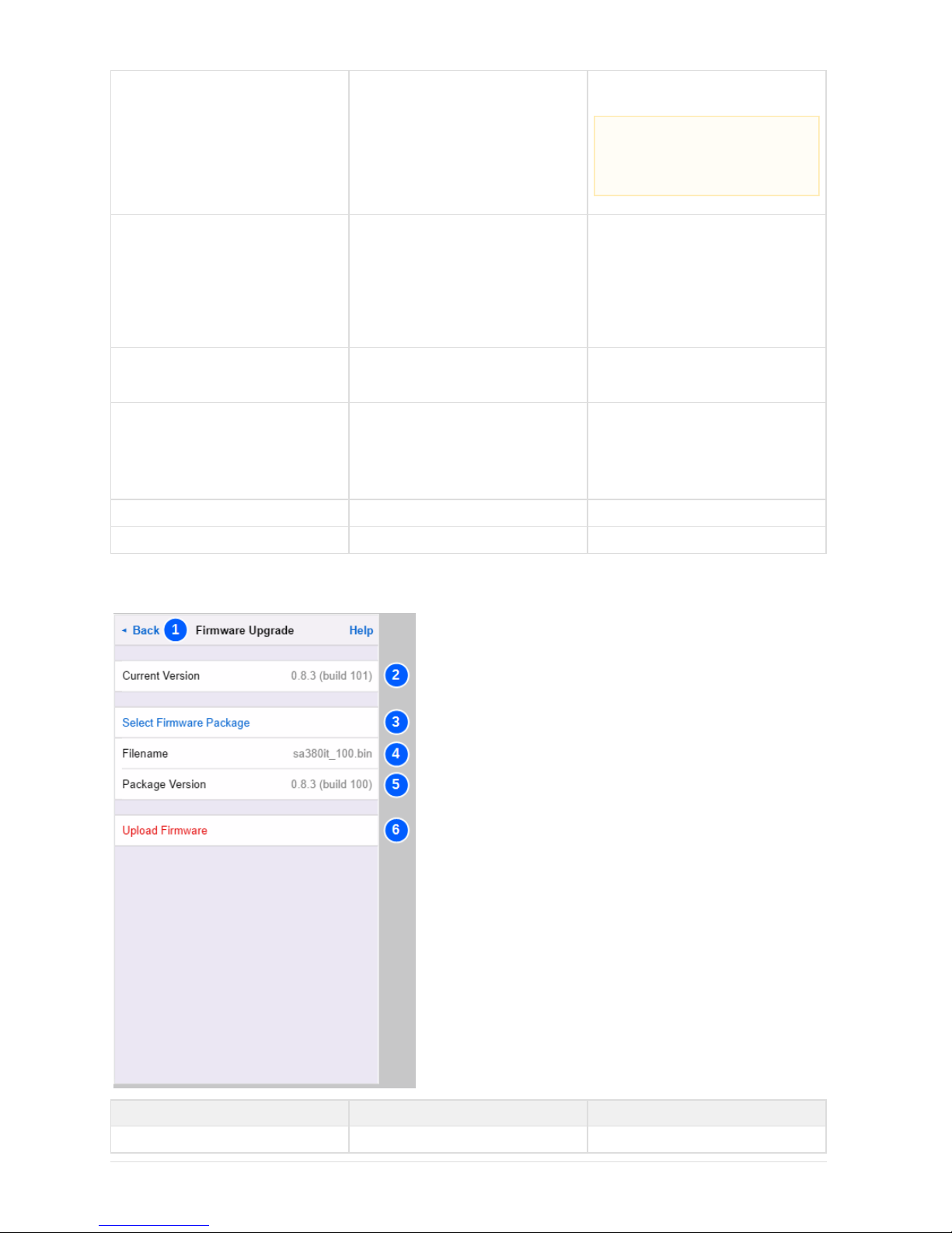
3 Reset Safety Interlocks
This will clear any safety interlocks that are
presently restricting measurement.
4 Restart Communications
This will drop any existing communication
link and attempt to build up the link again
from scratch.
When using the MIMOSA protocol this will
reset any back-off period.
When using the GSM modem, the modem
will restart.
5 Clear Queue
This will erase all pending messages
waiting to be sent to the server. The data
will be permanently lost.
6 Set Time From Browser
The SA380-IT requires the time to be set
before measurement can commence. This
is normally done through connection to
time server. In the event that a time server
is unavailable the time can manually be set
using this feature.
7 Reboot
Performs a software restart of the device.
8 Upgrade Firmware
Opens the "Upgrade Firmware" screen.
4.4.6 Upgrade Firmware
No. Name Description
1 Back
Navigates back to the Utilities menu.
Ensure that you have exhausted
all fault finding tasks prior to
manually resetting any device
interlock (see section 5.2)
Page 59
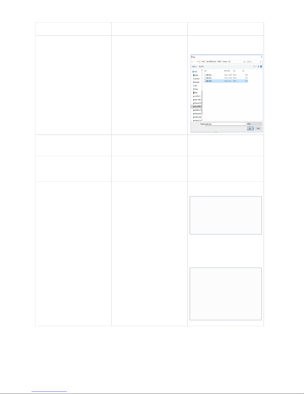
2 Current Version
Displays the currently installed Firmware
Version.
3 Select Firmware Package
Clicking here will open a file select
dialogue. Select a valid firmware (.bin) file
and hit "Open".
4 Filename Only visible once a valid firmware file
has been selected.
The name of the selected firmware file
5 Package Version Only visible once a valid firmware file
has been selected.
Displays the firmware version contained
within the selected file.
6 Upload Firmware Only visible once a valid firmware file
has been selected.
Click here to commence upgrade. A
progress bar will display firmware upload
progress.
Once upload is complete the SA380-IT will
restart to apply the upgrade.
4.4.7 Settings
In all cases, modified configuration items will be highlighted in green.
"Write Config" must be clicked to apply changes. This requires user authentication.
EAMS = Enterprise Asset Management System.
Authentication (username and
password) is required to upgrade
firmware.
Please contact MPEC or your
line manager to obtain the
correct credentials.
Accidental termination of
firmware upgrade will not harm
the SA380-IT, however I reboot
may be required to recommence
measurement in a timely manner
Without a restart the SA380-IT
will wait for 4 hours for the
remainder of the firmware file to
be uploaded, during which time,
measurement is suspended.
Page 60
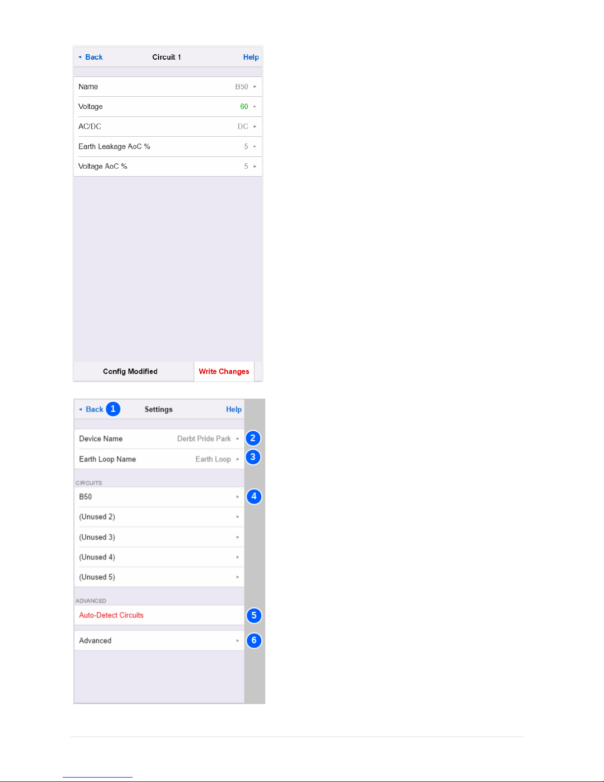
Page 61
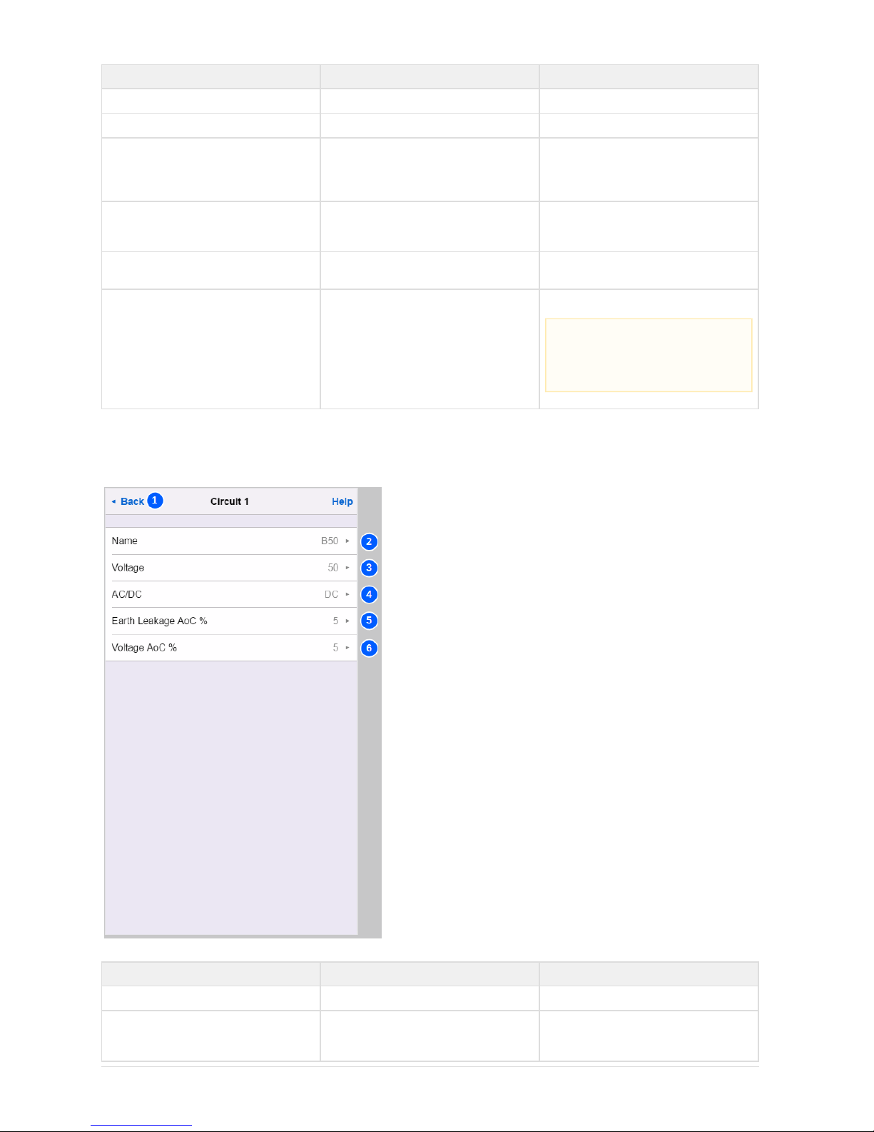
No. Name Description
1 Back
Navigates back to the Main menu.
2 Device Name
Click here to change the Device Name.
3 Earth Loop Name
Click here to change the name of the Earth
Loop circuit. This name will appear on the
live measurements screen and be
transmitted to the EAMS.
4 Monitored Circuits Settings
Click here to configure individual monitored
circuits. Unused inputs will display as
"unused "x
5 Auto Detect Circuits Click here to perform automated
configuration of all monitored circuits
6 Advanced
Opens the "Advanced" settings menu.
4.4.8 Monitored Circuit Settings
EAMS = Enterprise Asset Management System.
No. Name Description
1 Back
Navigates back to the Settings menu.
2 Name
The name of the circuit. This will appear on
the user interface to identify the circuit, and
will be transmitted to the EAMS.
The SA380-IT default settings
have been carefully chosen to be
for most installations. Modify
"advanced" settings with caution.
Page 62

3 Voltage
The nominal voltage of the monitored
circuit.
4 AC/DC
Click here to configure the circuit as an AC
or DC circuit. This affects voltage and earth
leakage measurement.
5 Earth Leakage AoC%
Sets the "Acquire-on-Change" threshold for
reporting "resistance to earth" change to
the EAMS (see section 2.10).
6 Voltage AoC%
Sets the "Acquire-on-Change" threshold for
reporting voltage change to the EAMS (see
section 2.10).
4.4.9 Auto Detect Circuits
Setting the voltage to "0" will
disable this circuit.
The monitored circuit voltage
is used to set over-voltage
thresholds. Incorrectly setting
this value could lead to a
dangerous situation in the
event of failure.
Incorrectly setting of AC / DC
will result in incorrect voltage
and earth resistance readings.
This settings applies to this
monitored circuit only.
This settings applies to this
monitored circuit only.
Page 63
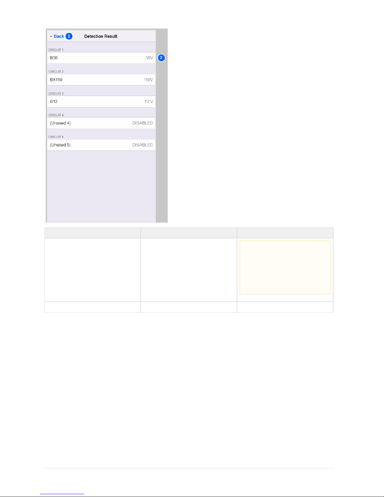
No. Name Description
1 Back
Navigates back to the Settings menu
Auto Detect will clear device
interlocks
Ensure that you have
exhausted all fault finding
tasks prior to manually
resetting any device interlock
(see section 5.2)
Page 64

2 Detection Results
The auto-detect feature is designed to
simplify commissioning of the SA380-IT.
For most applications, running and
verifying the result of the Auto-Detect
output is all that is required to configure the
SA380-IT.
The SA380-IT will measure each monitored
circuit in turn and set-up the channel to one
of the following based upon the measured
voltage:
Nearest Voltage Name AC / DC
12 V DC B12 DC
24 V DC B24 DC
50 V DC B50 DC
120 V DC B120 DC
110 V AC BX110 AC
Acquire on Change settings are set to
5% for all circuits.
If multiple circuits are detected with the
same nominal voltage they will be
named B50, B50(1), B50(2) etc.
If any of the settings are incorrect, they can
be modified using the "Monitored Circuit
Settings" screen.
4.4.10 Advanced
EAMS = Enterprise Asset Management System.
Advanced settings do not normally require modification. Do not modify any of these settings without an understanding of the
consequence.
Page 65
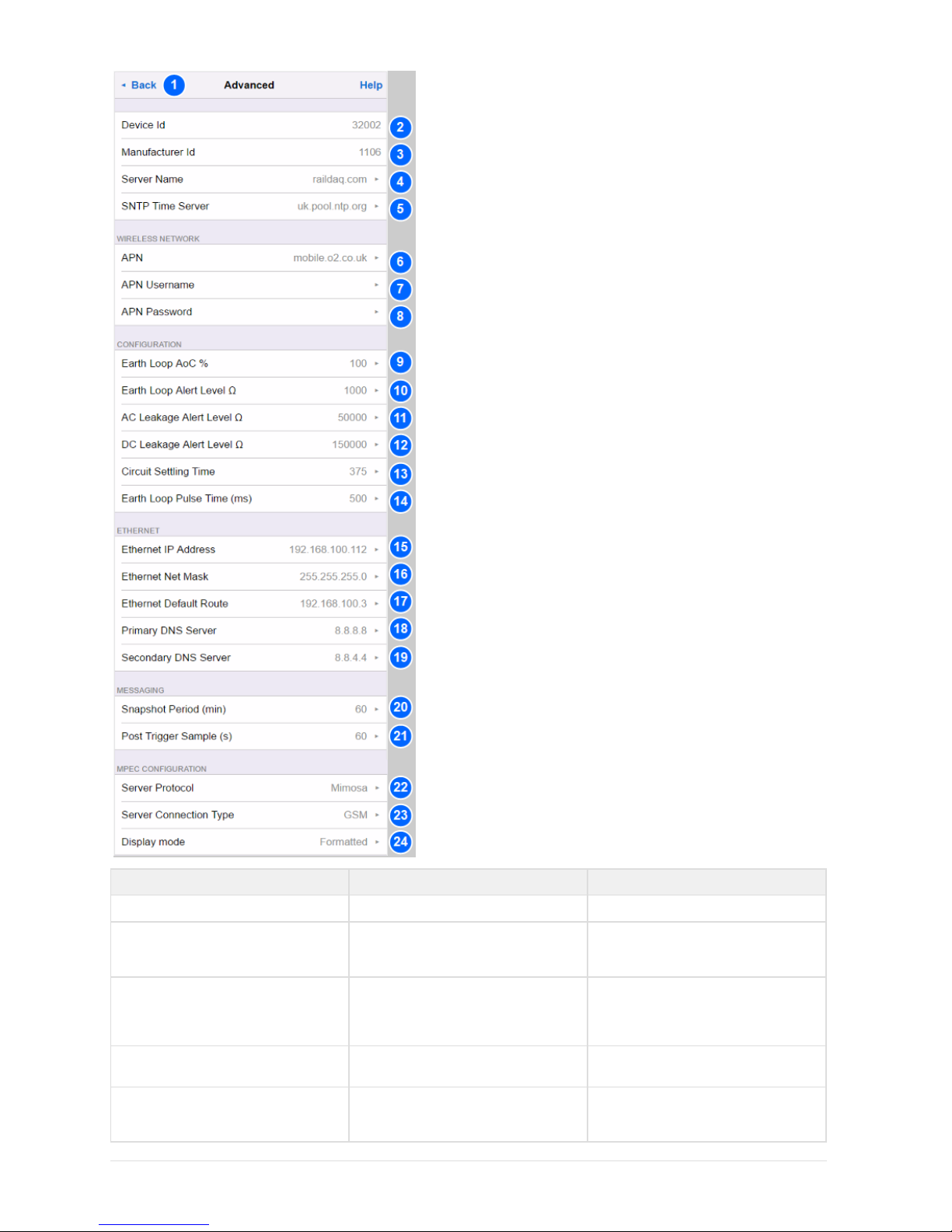
No. Name Description
1 Back
Navigates back to the Settings menu.
2 Device Id
The unique ID of this SA380-IT, used to
identify the device with the EAMS. This is
set at factory and cannot be changed.
3 Manufacturer Id
The MIMOSA manufacturer ID assigned to
MPEC Technology Ltd by the MIMOSA
foundation. This is set at factory and
cannot be changed.
4 Server Name
The URL or IP address of the EAMS entry
point for messaging.
5 SNTP Time Server
The URL or IP address of a time server
that the SA380-IT can use to update its
time if the EAMS is unreachable.
Page 66

6 APN
The name of the GSM access point the
SA380-IT is to connect to. It is set-up by
the SIM provider.
7 APN Username
Many GSM Access Points require
username and password authentication to
allow connection. Change these here.
8 APN Password
Many GSM Access Points require
username and password authentication to
allow connection. Change these here.
9 Earth Loop AoC %
Sets the "Acquire-on-Change" threshold for
reporting "earth loop resistance" change to
the EAMS (see section 4.10)
10 Earth Loop Alert Level
If the earth loop resistance exceeds this
level, the SA380-IT will report a hardware
fault and stop measurement of monitored
circuits.
11 AC Leakage Alert Level
If the resistance to earth of any AC
monitored circuit falls below this level, the
SA380-IT will report a earth fault.
12 DC Leakage Alert Level
If the resistance to earth of any DC
monitored circuit falls below this level, the
SA380-IT will report a earth fault.
13 Circuit Settling Time (ms)
This parameter governs the maximum
allowable time to measure the voltage and
resistance to earth of a individual
monitored circuit.
Ensure that the level is
appropriate for your
organisations needs and
complies with any legal safety
obligations.
Ensure that the level is
appropriate for your
organisations needs and
complies with any legal safety
obligations.
It is up to the user to specify an
appropriate time-out value,
based upon the trade-off
between desired accuracy and
speed of measurement.
The equation for calculating
measurement time per circuit
is: (750,000 x C ) + 0.3 seconds.
E
Where C is the maximum
E
expected capacitance to earth of
the monitored circuit. The
factory default is set at C = 1 F.
E
Page 67
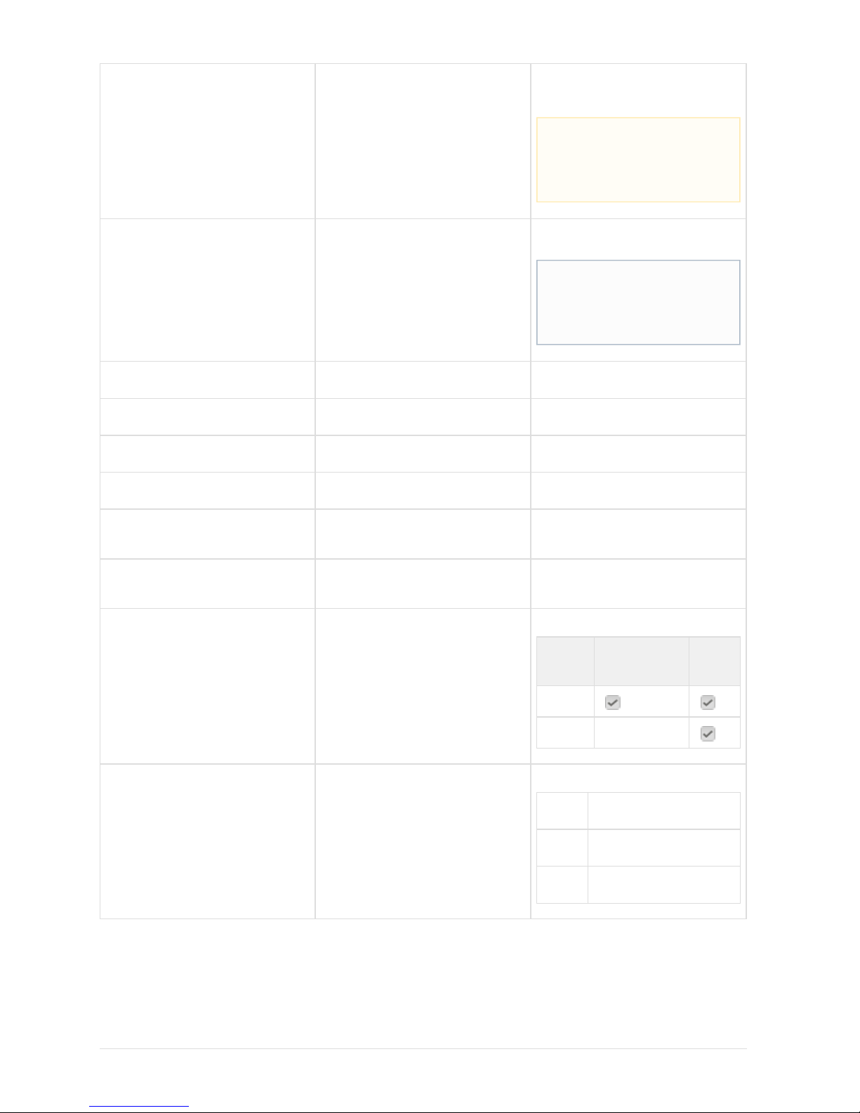
14 Earth Loop Pulse Time (ms)
This parameter governs the maximum
allowable time to measure the earth loop
resistance.
15 Ethernet IP Address
The fixed Ethernet IP address of the
SA380-IT.
16 Ethernet Net Mask
The IP Sub-net mask to allow sharing of IP
addresses.
17 Ethernet Default Route
The default route out of the SA380-IT to the
Internet.
18 Primary DNS Server
Primary domain name server to perform IP
address look-up.
19 Secondary DNS Server
Secondary domain name server to perform
IP address look-up.
20 Snapshot Period (min)
Period of time that must elapse before a
snapshot message is sent to the EAMS
(see section 4.10).
21 Post Trigger Sample (s)
Period of time that must elapse before
delayed acquisition is sent to the EAMS
(see section 4.10).
22 Server Protocol
Select the desired EAMS protocol:
Protocol Network Rail
Intelligent
Infrastructure
MPEC
Centrix
MIMOSA
RailDAQ
23 Server Connection Type
Select desired connection type:
GSM Use GSM exclusively for
server connection
Ethernet Use Ethernet exclusively for
server connection
any Use either GSM or Ethernet
for server connection
It is up to the user to specify an
appropriate time-out value,
based upon the trade-off
between desired accuracy and
speed of measurement.
This IP address is used for local
configuration and diagnostics. If
this IP address is changed you
must record the new IP address
on the front panel of the device.
Page 68
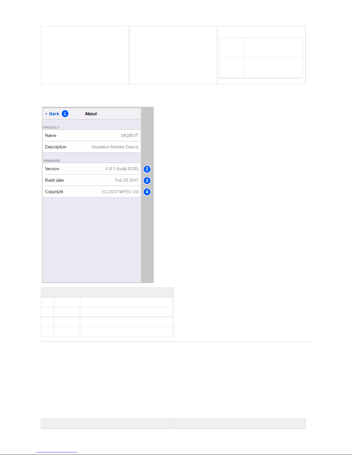
24 Display Mode
Select the desired display mode:
Raw Measured values are
displayed at full resolution
for debugging
Formatted Measured values are
displayed rounded for ease
of reading
4.4.11 About
No. Name Description
1 Back
Navigates back to the main menu.
2 Version
The deployed software version and build date.
3 Build Date
The date the firmware was created.
4 Copyright
Manufacturers copyright.
5) Faulting & Maintenance
The SA380-IT is designed to require minimal maintenance, with an anticipated product lifespan of 15 years. To maintain safe operation of the
device over its service life, the following faulting and maintenance activities are recommended.
5.1) Physical Inspection
An physical inspection of the SA380-IT is recommended.annual
Activity
Page 69
Clean Wipe the SA380-IT with dry cloth to remove dust and loose
particles.
Inspect Ensure all wiring is in good order and free of degradation.
Ensure the the SA380-IT enclosure is in sound condition.
Inspect
Ensure the SA380-IT does not have the indication lit.HW FAULT
In the event of an illuminated light, please consult section 5.2HW FAULT
5.2) Faulting Device Interlocks
Section 2.7 describes how the SA380-IT is continuously checking that all internal circuitry is functioning within established operating
parameters.
Whilst device interlocks are designed to only operate under genuine fault conditions, scenarios exist that cause them to falsely trigger. In
such scenarios it is desirable to manually clear device interlocks in order to recommence measurement.
There are four ways to clear device interlocks:
Power cycle the SA380-IT on-site.
Reboot the SA380-IT using the web-based tool.
Clear device interlocks using the web-based tool.
For self-clearing interlocks - remove the fault.
Clearing down a device interlock is unlikely to put the SA380-IT into a dangerous state, as the same self-checks that enabled the interlock
will re-enable the same interlock if the fault persists. Self-clearing device interlocks will automatically clear as soon as the fault is removed.
The table below shows all device interlocks, potential causes and remedies.
Genuine Hardware Fault Potential False-Trigger Self Clearing? Fault Finding Actions
Monitored Circuit
Under-Voltage
Resistive cable open circuit.
Internal measurement
circuit fault.
Circuit configured to
perform measurement,
however no circuit is
physically attached.
Circuit configured to
perform DC measurement,
however circuit is wired with
the incorrect polarity.
Circuit configured to expect
a DC voltage, however an
AC voltage is present.
Monitored circuit is
temporarily not energised.
Yes Check monitored circuit
wiring integrity
Replace resistive cable.
Disable unused circuits
using the web-based tool.
Ensure the correct voltage
type (AC/DC) is configured
for the monitored circuit.
Check monitored circuit for
voltage.
Negative Earth Loop
Resistance
Internal measurement
circuit fault.
Transient event on the earth
loop.
Yes Check earth loop wiring inte
grity.
High Earth Loop
Resistance
Earth loop wiring has
become disconnected.
Internal measurement
circuit Fault.
The installations earth loop
impedance is genuinely out
of tolerance.
Transient event on the earth
loop.
Yes Check earth loop wiring
integrity.
Check earth continuity of
the electrical installation.
In the event of enclosure damage, the SA380-IT is to be removed from service.immediately
Always investigate the cause of a device interlock before manually clearing it down.
Page 70
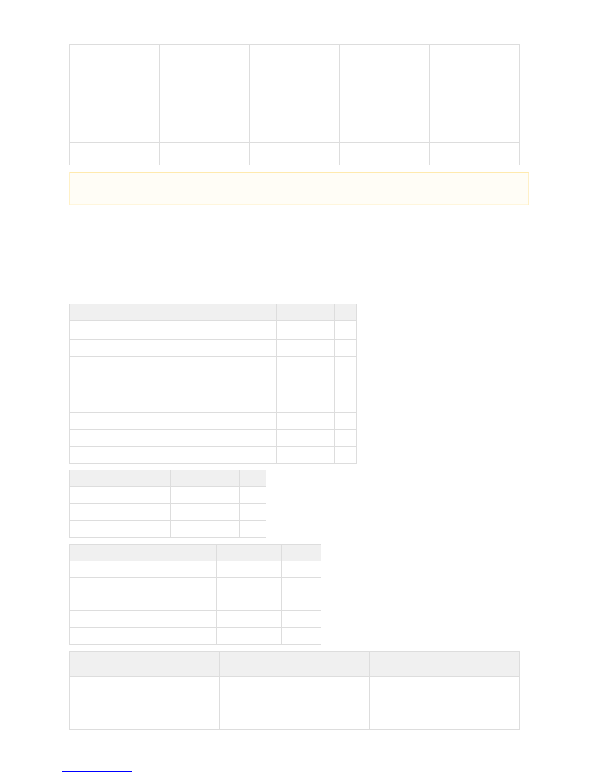
Monitored Circuit
Over-Voltage
Resistive cable short circuit.
Internal measurement
circuit fault.
Transient event on the
monitored circuit.
Circuit configured to monitor
a lower voltage than that
connected.
No Replace resistive cable.
Ensure the correct nominal
voltage is configured for the
effected circuit.
Ensure the correct voltage
type (AC/DC) is configured
for the monitored circuit.
Internal Relay Fault
Internal measurement
circuit fault.
Transient event on one of
the monitored circuits.
No None.
Out of Tolerance
Internal measurement
circuit fault.
Extreme temperature event. No None.
6) Technical Data
6.1) Specification
Insulation Coordination to EN50124-1 & EN60101-1
Nominal System Supply Voltage )(U
N
AC 110 V RMS
Over-voltage Category CAT IV
Rated Impulse Voltage Withstand )(U
Ni
4 kV
Pollution Degree 3
Rated Insulation Voltage (U )
Nm
AC 185V RMS
Inter-Monitored Circuit Isolation Voltage (Galvanic) +/- 400 V Peak Min.
Inter-Monitored Circuit Protective Impedance (in break-down) 140 k Min.
All devices undergo factory Hi-Pot testing
Supply Voltage
Operating Voltage Range AC 50-160 V RMS +15%
Operating Frequency Range 50 to 60 Hz
Max. Power Consumption 6 VA
Monitored Circuits Voltage
Number of Independent Circuits Monitored 5 AC or DC
Operating Voltage Range AC 5-160 V RMS
DC 5-160 V RMS
+15%
+15%
Operating Frequency Range DC to 60 Hz
Accuracy +/- 5 %
Monitored Circuits Insulation
Resistance
Equivalent Resistance to Earth (R
L =
R //R
B
)
N
0 to 5 M AC Circuits
Actual Resistance to Earth (R ) and R
B N
0 to 5 M DC Circuits
If device interlocks persist after fault finding actions have been exhausted the SA380-IT should be removed from service and
returned to MPEC for investigation.
Page 71

Accuracy +/- 1 k Z < 20 k
L
+/- 5 % * ZL >= 20 k
Alarm Value 1 k to 1 M
Factory Alarm Value 50 k
120 k
DC Circuits
AC Circuits
Fixed Hysteresis +5% AC and DC circuits
Standard Response Time (per circuit) T
R
1.1 s Typical
Actual Response Time (per circuit) T
R
(Assumes static impedance to earth)
(750,000 x C ) + 0.3
E
seconds
Product Response Time TR X Number of Circuits in Operation Typical
System Leakage Capacitance (CE)
(per circuit)
0.1 F
100 F
Min.
Max.
Factory Set Max. Leakage Capacitance (C
E
)
1 F per circuit
*See section 2.5 for an explanation of measurement accuracy with regard to the insulation resistance of DC monitored circuits.
*Accuracy de-rated to -5% to +6% in the presence of strong radiated EM fields at 20 V/m at 800 MHz to 1 GHz and 10 V/m at 1.4 GHz
to 2 GHz.
A typical mobile digital telecommunications device must be placed within 20 mm of the SA380-IT enclosure to experience these
levels.
Measuring Circuit
Measuring Voltage +/- 46 V
Measuring Current < 700 A
Internal Resistance & Impedance > 45 k no resistive cable fitted
System Resistance & Impedance > 70 k resistive cable fitted
Measuring Circuit is only connected to a
single Monitored Circuit at any one time
Internal System Check Frequency Every 30 s
Earth Loop Circuit
Measuring Voltage +/- 3.5 V Max.
Measuring Current < 500 A
System Resistance & Impedance > 25 k FE to SE
Tolerance to Stray Interference Voltage +/- 500 mV pk. Max.
Measurement Range 0 to 2 k
Accuracy +/- 0.5 RE < 10
+/- 5 % RE >= 10
Alarm Value 0 to 2 k
Factory Alarm Value 1 k
Fixed Hysteresis +5%
Output Ports
Page 72

Auxiliary Power Output 5 V
1 W
+/- 10 %
+/- 10 %
Volt-Free Contact Output N.O SPST
Volt-Free Contact Withstand Voltage +/- 100 V Pk Min.
Volt-Free Contact On Resistance 8 Max.
Volt-Free Contact Off Resistance 1 M Min.
Volt-Free Contact Current Handling 150 mA AC or DC RMS
Volt-Free Contact Mimimum Load 100 required to assure surge immunity
Serial Data Output EIA RS485
Wireless Modem (SIM Factory Fitted) SMA (Female) GSM 2G GPRS
Ethernet* RJ45 10/100 Mbs
Auto MDIX
*Ethernet is ordinarily for use as a monitoring port only. Ethernet port requires additional surge protection when used as a
permanent connection.
Supported Protocols
MPEC RailDaq
Efficient Data Communications
Ethernet
GSM
RS485
TCP/IP Port 7777
Port 7777TCP/IP
112,800 bps
Network Rail MIMOSA
Verbose Data Communications
Ethernet
GSM
TCP/IP Port 80
TCP/IP Port 80
SNTP
Time Synchronization
Ethernet
GSM
UDP Port 123
Port 123UDP
HTTP
Configuration and Live Data
Ethernet
GSM
TCP/IP Port 80
Port 80TCP/IP
Environmental
EMC Emissions & Immunity EN50121-4
Surge Immunity: Monitored Circuits & Earth EN61000-4-5 4kV
Voltage Withstand EN50124-1
EN61010-1
Climatic Class EN50125-3 T1 In cubicle
Ambient Operating Temperature -25 °C to +70 °C
Storage Temperature -40 °C to +85 °C
Humidity 5 % to 100 % Condensing
Vibration
2.3 m/s
2
3 - axis'
Impact Protection IK06
Ingress Protection IP52
Flammability Rating UL94 V0
ESD Not protected Observe ESD handling precautions
Page 73
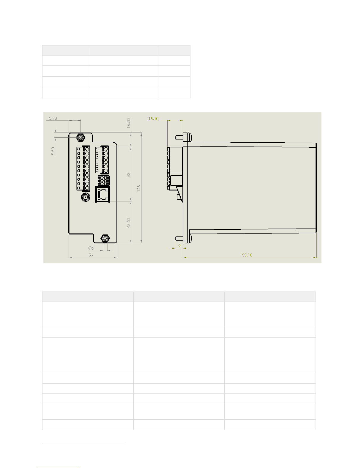
6.2) Mechanical
Installation Data
Mounting BR930 / Q Style Mounting Plate
Primary Connections
Wire Size: 2.5 mm max.
2
Spring Clamp
Auxiliary Connections
Wire Size: 1.5 mm2 max.
Spring Clamp
Weight 350g
6.3) Ordering Details
Description MPEC Part No. NR PADs No.
SA380-IT Multiple Bus-Bar Insulation
Monitor Device.
Without plug couplers or cables
SA380-IT-NR TBC
Plug coupler and cable kit SA380-IT-KT TBC
SA380-IT Multiple Bus-Bar Insulation
Monitor Device.
With plug couplers and cables
(SA380-IT-NR + SA380-IT-KT + GSM
Antenna)
SA380-IT-SD TBC
SA380-IT Spare Connector Set SA380-IT-CN TBC
SA380-IT 47K Resistive Cable - 3 meters SA380-IT-RC TBC
SA380-IT Lightning to Ethernet Cable SA380-IT-LE TBC
SA380-IT Hand-held Configuration and
Diagnostics Device
SA380-IT-CD TBC
SA380 Series Hinged Wall Bracket BRK-HINGE TBC
Page 74

Base Unit Kit Contents
(MPEC Part No. SA380-IT-NR)
Qty
SA380-IT Module 1
M5 Spring Washer 2
M5 Nut 2
Plug Coupler and Cable Kit Contents
(MPEC Part No. SA380-IT-KT)
Qty
10 Way 5 mm Pitch Connector 1
6 Way 5 mm Pitch Connector 1
6 Way 3.5 mm Pitch Connector 1
3 m Resistive Cable 8
6 m grey A1 0.75 mm signalling cable 1
SA380-IT-SD: Orders over 10 units will be shipped with 1 complimentary Ethernet-to-Lightning cable for every full 10 units ordered.
24
 Loading...