

MPE XR III Operator's Manual

OPERATING AND SERVICE MANUAL
XR SERIES III
DC POWER SUPPLIES


MAGNA-POWER ELECTRONICS, INC.
39 ROYAL ROAD, FLEMINGTON, NJ 08822
February 20, 2012

SAFETY NOTICE
Before applying power to the system, verify that the unit is configured properly for the user’s
particular application.
CE recognition of XR Series power supplies is based on rack mounted applications only. Use of
these power supplies outside of a rack mount equipment enclosure will expose the user to high
voltage and/or high current sources. Extreme caution must be used under these circumstances.
Two or more XR Series power supplies may be connected in series. Regardless of the number
of units or the voltage ratings of the series connected power supplies, the voltage potential from
any output terminal to chassis ground should not exceed 1000 Vdc.
Installation and service must be performed only by properly trained and qualified personnel who
are aware of dealing with electrical hazards. Ensure that the ac power line ground is properly
connected to the power supply chassis. Furthermore, other power grounds, including those
connected to application maintenance equipment, must be grounded for both personnel and
equipment safety.
Always ensure that facility ac input power is de-energized prior to connecting or disconnecting
the input and output power cables.
Caution: Lethal voltages may be present inside the power supply even when the
ac input voltage is disconnected. Only properly trained and qualified personnel
should remove covers and access the inside of the power supply.
During normal operation, the operator does not have access to hazardous voltages within the
cabinet. Depending on the user’s application, high voltages hazardous to human safety may be
generated normally on the output terminals. Ensure that the output power cables are properly
labeled as to the safety hazards and that any inadvertent contact with hazardous voltages is
eliminated.
This power supply is designed to be permanently connected to the power source requiring a
readily accessible disconnect device incorporated in the fixed wiring.
These operating instructions form an integral part of the equipment and must be available to the
operating personnel at all times. All the safety instructions and advice notes are to be followed.
Neither Magna-Power Electronics, Inc. nor any of the associated sales organizations can accept
responsibility for personal injury, consequential injury, loss, or damage that results from
improper use of the equipment and accessories.
i

LIMITED WARRANTY
The following is made in lieu of all warranties expressed or implied.
Magna-Power Electronics, Inc. warranties its products to be free of manufacturing defects for a
period of two (2) years from date of original shipment from its factory. Magna-Power
Electronics, Inc. will repair, replace, or refund the purchase price at its discretion, which upon
examination by Magna-Power Electronics, Inc., is determined to be defective in material or
workmanship, providing such claimed defective material is returned upon written authorization
of Magna-Power Electronics, Inc., freight prepaid.
For products failing within the first 30 days of the warranty period, Magna-Power Electronics,
Inc. will return the repaired product at its expense using a standard shipping method; after 30
days of the warranty period, the repaired product will be returned at the customer’s expense
using the customer’s requested shipping method.
Damage due to corrosion, customer alterations, excessive dust, extreme environmental or
electrical conditions, and/or misuse will be evaluated upon inspection. If inspection reveals that
the cause of damage is not due to materials or workmanship, repair of the product will be treated
on a non-warranty basis.
All electrical, commercial supply parts, and items not manufactured by Magna-Power
Electronics, Inc. shall carry the warranty of the original manufacturer and no more, but under no
circumstances to exceed the warranty period. Replacement parts shall be warranted for a period
of 90 days.
Warranty labor shall only apply if the product, assembly, or part is returned to the factory freight
prepaid and insured. Damage or breakage while in transit is not covered by this warranty.
Magna-Power Electronics, Inc. assumes no responsibility to Buyer for labor to diagnose and
remove defective product and installation of replacement product. Furthermore, Magna-Power
Electronics, Inc. is not liable to Buyer or to any third party for consequential or incidental
damages under any circumstances, whether due to defect in the product, due to delay or failure
of delivery, due to a failure of the product to perform as specified, or for any other reason or
cause. Buyer and Magna-Power Electronics, Inc. agree that Buyer’s sole remedy and MagnaPower Electronics, Inc.’s sole liability to Buyer is limited to repair, replacement, or refund of
the purchase price of the product as described herein, whether Buyer’s claim arises out of
contract or in tort.
All claims against the warranty shall be the final determination of Magna-Power Electronics,
Inc.
ii

CLAIM FOR DAMAGE IN SHIPMENT
This instrument received comprehensive mechanical and electrical inspections before shipment.
Immediately upon receipt from the carrier, and before operation, this instrument should be
inspected visually for damage caused in shipment. If such inspection reveals internal or external
damage in any way, a claim should be filed with the carrier. A full report of the damage should
be obtained by the claim agent and this report should be forwarded to us. We will then advise
you of the disposition to be made of the equipment and arrange for repair or replacement. When
referring to this equipment, always include the model and serial number.
RETURNING EQUIPMENT
Before returning any equipment to the factory, the following steps should be taken:
1. Contact our technical service department. Give a full description of the difficulty and
include the model and serial number of the unit. On receipt of this information, we will
give you service information or shipping instructions.
2. Packaging and method of shipment must be coordinated with the factory to insure safe
delivery. All equipment returned for repair require a Return Authorization Number and
must be insured. No returns will be accepted without assignment of a Return
Authorization Number.
3. For non-warranty repairs, we will submit a cost estimate for your approval before
proceeding.
iii

TABLE OF CONTENTS
Section Title Page
1.0 GENERAL INFORMATION 1
1.1 Description 1
1.2 Features 1
1.3 IEC Symbols Used in Manual 4
1.4 Power Requirements 4
1.5 Specifications 4
2.0 INSTALLATION AND POWER ON CHECK 18
2.1 Cooling 18
2.2 AC Input Connections 18
2.3 DC Output Connections 19
2.4 General Operation 19
2.5 Controls and Indicators 21
2.6 Preparation for Use 21
2.6.1 Unpacking 21
2.6.2 Electrical Check 21
2.6.2.1 XR Series Models 21
2.6.2.2 XRC Series Models 22
3.0 OPERATION 25
3.1 Front Panel Commands 25
3.1.1 Run Mode Commands 25
3.1.2 Set Point Commands 26
3.1.3 Configuration Commands 28
3.1.4 Calibration Commands 31
3.2 Modes of Operation 33
3.2.1 Normal Mode 33
3.2.2 Constant Voltage 33
3.2.3 Constant Current 34
3.3 Remote Sensing 34
3.4 External Programming 35
3.4.1 Resistive Programming 37
3.4.2 Voltage Programming 37
3.4.3 Current Programming 38
3.5 Voltage and Current Monitoring 38
3.6 Digital Input and Output Lines 38
3.7 Diagnostic Functions 39
3.8 Parallel Operation 41
3.8.1 Parallel Operation - Direct 42
3.8.2 Parallel Operation - Master/Slave 42
iv

3.9 Series Operation 43
3.9.1 Series Operation - Direct 44
3.9.2 Series Operation - Master/Slave 44
3.10 Pulse Loading 45
3.11 Nomenclature 45
4.0 PROGRAMMING WITH SCPI COMMANDS 48
4.1 Command Features 48
4.2 Electrical Testing Using RS232 Communications 48
4.3 SCPI Subsystem Commands 49
4.3.1 Source Subsystem 49
4.3.1.1 VOLT and VOLT:TRIG 50
4.3.1.2 VOLT:PROT 51
4.3.1.3 CURR and CURR:TRIG 51
4.3.1.4 CURR:PROT 52
4.3.1.5 PER (not available for XR Series power supplies) 53
4.3.2 Measure Subsystem 53
4.3.2.1 MEAS:VOLT? 53
4.3.2.2 MEAS:CURR? 54
4.3.3 System Subsystem 54
4.3.3.1 SYST:VERS? 54
4.3.3.2 SYST:ERR? 54
4.3.4 Status Subsystem 55
4.3.4.1 Operation Register 55
4.3.4.2 Questionable Register 56
4.3.5 Output Subsystem 56
4.3.5.1 OUTP? 56
4.3.5.2 OUTP:ARM (not available for XR Series power supplies) 57
4.3.5.3 OUTP:START 57
4.3.5.4 OUTP:STOP 58
4.3.5.5 OUTP:PROT:CLE 58
4.3.6 Abort Subsystem 58
4.3.7 Trigger Subsystem 59
4.3.8 Initiate Subsystem 59
4.3.9 Calibrate Subsystem 60
4.3.9.1 CAL:IDN 60
4.3.9.2 CAL:PASS 60
4.3.9.3 CAL:POT 61
4.3.9.4 CAL:SCAL:VOLT 61
4.3.9.5 CAL:SCAL:CURR 61
4.3.9.6 CAL:SCAL:INP 62
4.3.9.7 CAL:DEF 62
4.3.9.8 CAL:STOP 62
4.3.10 Configure Subsystem 63
v

4.3.10.1 REM:SENS 63
4.3.10.2 CONT:INT 63
4.3.10.3 CONT:EXT 64
4.3.10.4 INTE 64
4.3.10.5 CONF:SETPT 64
4.3.11 GPIB Communications Subsystem 65
4.3.11.1 GPIB:VERS? (Optional GPIB only) 65
4.3.11.2 GPIB:ADDR (Optional GPIB only) 65
4.3.12 Ethernet Communications Subsystem 66
4.3.12.1 NET:VERS? (Optional Ethernet only) 66
4.3.12.2 NET:MAC? (Optional Ethernet only) 66
4.3.12.3 NET:SER? (Optional Ethernet only) 67
4.3.12.4 NET:ADDR (Optional Ethernet only) 67
4.3.12.5 NET:GATE (Optional Ethernet only) 67
4.3.12.6 NET:SUBN (Optional Ethernet only) 68
4.3.12.7 NET:PORT (Optional Ethernet only) 68
4.3.12.8 NET:HOST? (Optional Ethernet only) 69
4.3.12.9 NET:DHCP (Optional Ethernet only) 69
4.3.13 Recall Subsystem 69
4.3.14.1 MOD:TYPE:SEL 70
4.3.14.2 MOD:TABL 71
4.3.14.3 MOD:SAVE 72
4.3.14.4 MOD:TABL:LOAD 73
4.3.15 SCPI Data Formats 73
4.4 IEEE-488 Event Processing 74
4.5.1 Clear 74
4.5.2 Read Event Status Register 75
4.5.3 Read and Set Event Status Enable Register 77
4.5.4 Read Status Byte Register 77
4.5.5 Read and Set Service Request Enable Register 78
4.5.6 Read Model Number, Part Number, and Serial Number 78
4.5.7 Save 79
4.5.8 Recall 79
4.5.9 Reset 80
4.6 Error Messages 80
4.7 Restricted Command Set 81
5.0 INTERFACING USING THE REMOTE INTERFACE SOFTWARE 84
5.1 Application Setup 84
5.2 Virtual Control Panel 84
5.3 Command Panel 86
5.4 Register Panel 86
5.5 Calibration Panel 88
5.6 Firmware Panel 89
vi

5.7 Modulation Panel 89
6.0 PRINCIPLE OF OPERATION 92
7.0 MAINTENANCE AND TROUBLE SHOOTING 95
7.1 General 95
7.2 Trouble Shooting Guide 95
7.3 Calibration 96
7.3.1 Control Board 96
7.3.1.1 Reference Amplifier Calibration 96
7.3.1.2 Voltage Feedback Amplifier Calibration 96
7.3.1.3 Current Feedback Amplifier Calibration 96
7.3.2 Driver Board 96
7.3.2.1 Over Current Protection 97
7.3.2.2 Under Voltage Protection 97
8.0 APPLICATIONS 98
8.1 General 98
8.2 Leadless Remote Sensing 98
8.3 Photovoltaic Cell Simulator 98
8.4 Battery Charger 100
8.6 High-Slew Rate Option 104
APPENDIX A IEEE-488 COMMUNICATIONS 105
A.1 IEEE-488 Communications using the Remote Interface Software 105
A.2 IEEE-488 Communications with MAX 105
APPENDIX B ETHERNET COMMUNICATIONS 107
B.1 Ethernet Communications using the Remote Interface Software 107
B.2 Ethernet Communications using HyperTerminal 107
B.3 Ethernet Communications using a Web Page Browser 108
B.3.1 Connectivity 108
B.3.2 Discovery 109
B.3.2.1 Discovery using NI Measurement & Automation Explorer 109
B.3.2.2 Discovery using Agilent Connection Expert 109
B.3.2.3 Discovery using the Remote Interface Software 109
B.3.3 Web Interface 109
APPENDIX C USB COMMUNICATIONS 113
C.1 Edgeport/1 Setup 113
C.2 Edgeport/1 Communications using the Remote Interface Software 113
APPENDIX D RS485 COMMUNICATIONS 114
D.1 485DSS Initial Setup 114
vii

D.2 HyperTerminal Setup 114
D.3 485DSS Address Command 115
D.4 485DSS Communications using HyperTerminal 115
viii

1.0 GENERAL INFORMATION
1.1 Description
This manual contains operation and maintenance instructions for Magna-Power Electronics' XR
Series, current fed power supplies. These power supplies are constant voltage/constant current
sources suitable for a wide range of applications.
1.2 Features
Magna-Power Electronics’ XR Series combines the best of dc power processing with
multiprocessor embedded control. Magna-Power Electronics’ innovative power processing
technology improves response, shrinks package size, and reduces cost. XR Series power
supplies are current fed and are more tolerant to abusive loads than conventional switching
power supplies.
XR Series power supplies can operate as a voltage source or a current source depending on the
control settings and load conditions. If the power supply is operating as a voltage source and the
load increases to a point beyond the current command setting, the power supply automatically
crosses over to current mode control and operates as a current source at that setting.
XR Series power supplies incorporate an optically isolated feedback system. The result is that
all user interface circuitry is referenced to earth ground -- not the negative terminal of the power
supply. This enables users to connect external circuitry without concern of ground loops or
voltage breakdown.
XR Series power supplies offer both master/slave parallel and series operation. This enables two
or more power supplies to be placed in parallel for increased output current or in series for
increased output voltage. With master/slave operation, power supplies operate at near equal
voltage and current.
XR Series power supplies can be configured through the front panel for different applications.
The power supply can be programmed to have its control functions accessible from the front
panel, rear connector, or with RS232, optional IEEE-488, or optional Ethernet communications.
External RS485 to RS232 and external USB to RS232 converters are also available to echo
commands over the communications network. Communication options must be specified at time
of order. XR Series power supplies support a full set of SCPI commands. Drivers are available
for LabWindows/CVI, LabVIEW, and IVI.
Sensing can be established at the output terminal of the power supply or through a rear terminal
block for sensing at the load. A smart remote sense detector checks whether or not sense leads
are present eliminating the potential of uncontrolled operation. An external interlock can be set
to enable operation only when an external connection is made. Even calibration has been
simplified with front panel access to calibration digital potentiometers.
1

XR Series power supplies have three levels of over voltage/current protection: shutdown of
controlling insulated gate bipolar transistors (IGBT’s), disconnect of main power, and input
fuses. After an over voltage/current trip condition, the supply must be reset.
XR Series power supplies have push button start/stop controls. These controls are tied to a
mechanical contactor which operates with the electronic switches to break the ac mains when
stop is commanded. Unlike competing products, an off means both an electrical and mechanical
break in the power circuit — not a break in an electronic switch. Safety comes first at MagnaPower Electronics.
XR Series power supplies are available with two alternative front panels: XR Version for
analog/digital control and C Version for computer or programmable logic control. All XR Series
power supplies employ the same power processing engine. Table 1.1 shows a comparison
between the different models.
XR Series models utilizing the XR Version front panel provide stepless analog control from
front panel potentiometers. With simple configuration changes, voltage, current, over voltage
trip, and over current trip may be programmed from the rear connector or with RS232, optional
IEEE-488, or optional Ethernet communications. XR Series power supplies with XR Version
front panels are well suited for industrial and laboratory applications.
XR Series power supplies with XR Version front panels offer an analog input to modulate the
voltage or current setting using piecewise linear approximation. This feature enables the voltage
or current setting to be adjusted by a sensor input, such as a thermistor, or by monitoring its own
voltage or current. Modulation allows the output to be tailored for advanced process control
applications, battery charging, and source emulation.
XR Series models utilizing the C Version front panel only allow control from the rear connector
or with RS232, optional IEEE-488, or optional Ethernet communications. These models are
intended for process control applications where front panel controls and displays are not required
or desired.
Remote Interface Software is included to provide sophisticated computer control. This software
provides a virtual control panel to emulate the power supply’s front panel, a command panel to
send and monitor SCPI commands, a register panel to monitor registers, a calibration panel to
provide easy access to calibrate digital potentiometers, a firmware panel to upgrade the control
microprocessor, and a modulation panel to easily program modulation parameters.
2

Table 1.1 COMPARISON CHART OF FRONT AND REAR
PANEL CONTROLS AND INDICATORS
MODELS
Features
XRC XR
FRONT PANEL CONTROLS
Power on/off
Start/Stop
Rotary voltage/current entry
Menu/Item
Display settings
Enter/Clear
!
!
!
!
!
!
!
INDICATORS
Voltage/current set point
OVT/OCT set point
Voltage/current output
Internal/external control
Alarms
Rotary/external/remote programming
Remote sense enabled
!
!
!
!
!
!
!
REAR PANEL CONTROLS
Voltage/current set point
OVT/OCT set point
Modulation set point
Voltage/current output
Internal/external control
Alarm outputs (8 lines)
Status outputs (6 lines)
Master/Slave connections
Remote sense inputs
RS232 inputs/outputs
Optional IEEE-488 inputs/outputs
Optional Ethernet inputs/outputs
Interlock enable
!
!
!
!
!
!
!
!
!
!
!
!
!
!
!
!
!
!
!
!
!
!
!
!
!
!
3

XR Series models have extensive diagnostic functions -- all of which when activated take
command to shut down the system. Diagnostic functions include phase loss, excessive thermal
conditions, over voltage trip, over current trip, and program line. Program line monitors
externally applied analog set point signals to insure they are within the specified range. Upon a
diagnostic fault condition, main power is disconnected and the diagnostic condition is latched
into memory. Pressing the clear key clears the memory. All diagnostic functions can be
monitored through a rear connector. Furthermore, control functions can also be set through the
rear connector to allow simultaneous control of one or more XR Series units.
1.3 IEC Symbols Used in Manual
The following IEC symbols are used in this manual.
Caution, risk of electric shock
Caution, risk of danger
Protective conductor terminal
Three-phase alternating current
1.4 Power Requirements
XR Series power supplies are manufactured to operate on 208/240 V, 380/415 V, or 440/480 V
50 to 400 Hz mains.
The standard operating voltage is 208 V, 3φ, 50 to 400 Hz unless otherwise specified at time of
order. For conversion from 208 V to 240 V operation, two internal wiring changes must be
made. The locations are not accessible to the user and the power supply must be returned to the
factory for modification.
XR Series power supplies are optionally available to operate on 380 V or 480 V, 3φ, 50 to 400
Hz mains. For conversion from 380 V to 415 V or from 480 V to 440 V operation, two internal
wiring changes must be made. The locations are not accessible to the user and the power supply
must be returned to the factory for modification.
1.5 Specifications
The following specifications describe the published operational characteristics of the XR Series
power supplies.
4

Input voltage:
208 Vac (operating range 187 - 229 Vac), 50 - 400 Hz (operating range 45 - 440 Hz), 3φ;
240 Vac (operating range 216 - 264 Vac), 50 - 400 Hz (operating range 45 - 440 Hz), 3φ;
380 Vac (operating range 342 - 418 Vac), 50 - 400 Hz (operating range 45 - 440 Hz), 3φ;
415 Vac (operating range 373 - 456 Vac), 50 - 400 Hz (operating range 45 - 440 Hz), 3φ;
440 Vac (operating range 396 - 484 Vac), 50 - 400 Hz (operating range 45 - 440 Hz), 3φ;
480 Vac (operating range 432 - 528 Vac), 50 - 400 Hz (operating range 45 - 440 Hz), 3φ.
208 Vac (operating range 187 - 229 Vac), 50 - 400 Hz (operating range 45 - 440 Hz), 1φ;
240 Vac (operating range 216 - 264 Vac), 50 - 400 Hz (operating range 45 - 440 Hz), 1φ.
Line regulation:
Voltage Mode: ±0.004% of full scale,
Current Mode: ±0.02% of full scale.
Load regulation:
Voltage Mode: ±0.01% of full scale,
Current Mode: ±0.04% of full scale.
Stability: 0.10 % for 8 hours after 30 minute warm up.
Maximum Slew Rate for standard models:
100 ms for an output voltage change from 0 to 63%,
100 ms for an output current change from 0 to 63%.
Maximum Slew Rate for optional high-slew rate models:
4 ms for an output voltage change from 0 to 63%,
8 ms for an output current change from 0 to 63%.
Bandwidth for standard models:
3 Hz with remote analog voltage programming,
2 Hz with remote analog current programming.
Bandwidth for optional high-slew rate models:
60 Hz with remote analog voltage programming,
45 Hz with remote analog current programming.
Load transient response:
2 ms to recover within ±1% of regulated output with a 50% to 100% or 100% to 50% step load
change.
Efficiency: greater than 86%, see Model and Ratings tables for details.
Temperature coefficient:
5

0.04 %/EC of maximum output voltage,
0.06 %/EC of maximum output current.
Isolation:
User inputs and outputs: referenced to earth ground,
Maximum input voltage to ground: ±2500 Vac,
Maximum output voltage to ground: ±1000 Vdc.
Power Factor: greater than 92% at maximum power, 3φ inputs,
greater than 70% at maximum power for 1φ inputs.
Ambient Temperature: 0 to 50EC.
Storage Temperature: -25 to +85EC.
Remote sense limits: 3% maximum voltage drop from output terminals to load.
Remote analog programming limits:
Voltage set point: 0 to 10.0 Vdc for 0 to 100% output,
Current set point: 0 to 10.0 Vdc for 0 to 100% output,
Over voltage trip set point: 0 to 10.0 Vdc for 0 to 110% output,
Over current trip set point: 0 to 10.0 Vdc for 0 to 110% output,
Modulation: 0 to 10 Vdc.
Remote analog input impedance: 10K for all inputs.
Remote analog programming accuracy of full scale:
Voltage set point: ±0.075%,
Current set point: ±0.075%,
Over voltage trip set point: ±0.075%,
Over current trip set point: ±0.075%.
Analog monitoring and reference:
Output voltage: 0 to 10.0 Vdc, 5 mA,
Output current: 0 to 10.0 Vdc, 5 mA,
+10V Ref: 10.0 Vdc, 5 mA,
Analog output impedances:
Voltage output monitoring: 100 ohm,
Current output monitoring: 100 ohm,
+10V Ref: 1 ohm.
Analog monitoring accuracy of full scale:
Output voltage: ±0.2%,
6

Output current: ±0.2%,
+10V Ref: ±.50%.
Digital programming accuracy of full scale:
Voltage set point: ±0.075%,
Current set point: ±0.075%,
Over voltage trip set point: ±0.075%,
Over current trip set point: ±0.075%.
Digital readback accuracy of full scale:
Output voltage: ±0.2%,
Output current: ±0.2%.
Digital control inputs and outputs limits:
Input voltage: 0 to 5 Vdc, 10K input impedance;
Output voltages: 0 to 5 Vdc, 5 mA drive capacity per line;
5 V supply: 25 mA.
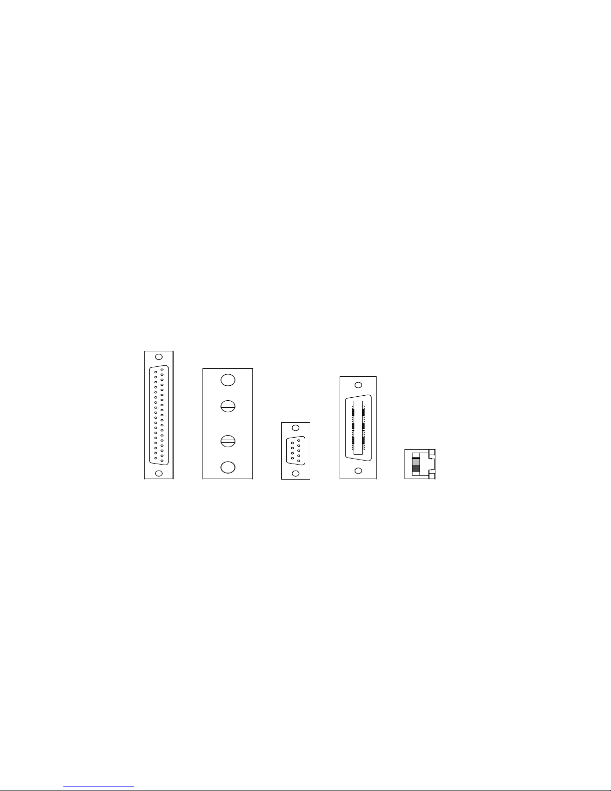
User interface connectors, see figure 1.1 and Tables 1.5, 1.6, 1.7, 1.8, and 1.9 for details:
JS1: 37 pin D-Subminiature, female;
JS2: 2 terminal 6-32 screw connector;
JS3: 9 pin D-Subminiature, female.
JS4: optional 24 pin IEEE-488, female.
JS5: optional 8 pin RJ45, female.
RS232 interface:
Baud Rate: 19200 Baud,
Data Size: 8-bit,
Parity: None,
Stop bits: 1.
Optional Ethernet Interface:
IP address: 169.254.x.x
Subnet Mask: 255.255.0.0
Default Getaway: 0.0.0.0
DNS Server: 0.0.0.0
Size and Weight: see figure 1.2 and Table 1.4 for details.
Agency Approvals:
CE-marked units meet the following standards:
EN61010-1:2001-02 Safety Requirements for Electrical Equipment for
7
Measurement, Control, and Laboratory Use
2004/108/EC EMC Directive
EN61000-6-3:2001 and EN61000-6-3:2001 General Emissions Standard
EN55022 Class A Product Specifications Emissions
EN61000-6-1:2001 Generic Immunity Standard
• EN61000-4-2 Electrostatic Discharge
• EN61000-4-3 Radiated Susceptibility
• EN61000-4-4 Electrical Fast Transient/Burst
• EN61000-4-6 Conducted Susceptibility
• EN61000-4-8 Magnetics
• EN61000-4-11 Voltage Dips & Interruptions
Optional Ethernet Interface units meet the following standards
LXI Class C, Revision 1.2
37
20
19
1
2
9
1
(b)
6
(c)(a)
24 12
5
1
113
8
1
(d) (e)
Figure 1.1 Connector (a) JS1, remote interface; (b) JS2, remote sense; ( c) JS3, RS232; (d)
JS4, IEEE-488; and (e) JS5, Ethernet (viewed from female end)
8
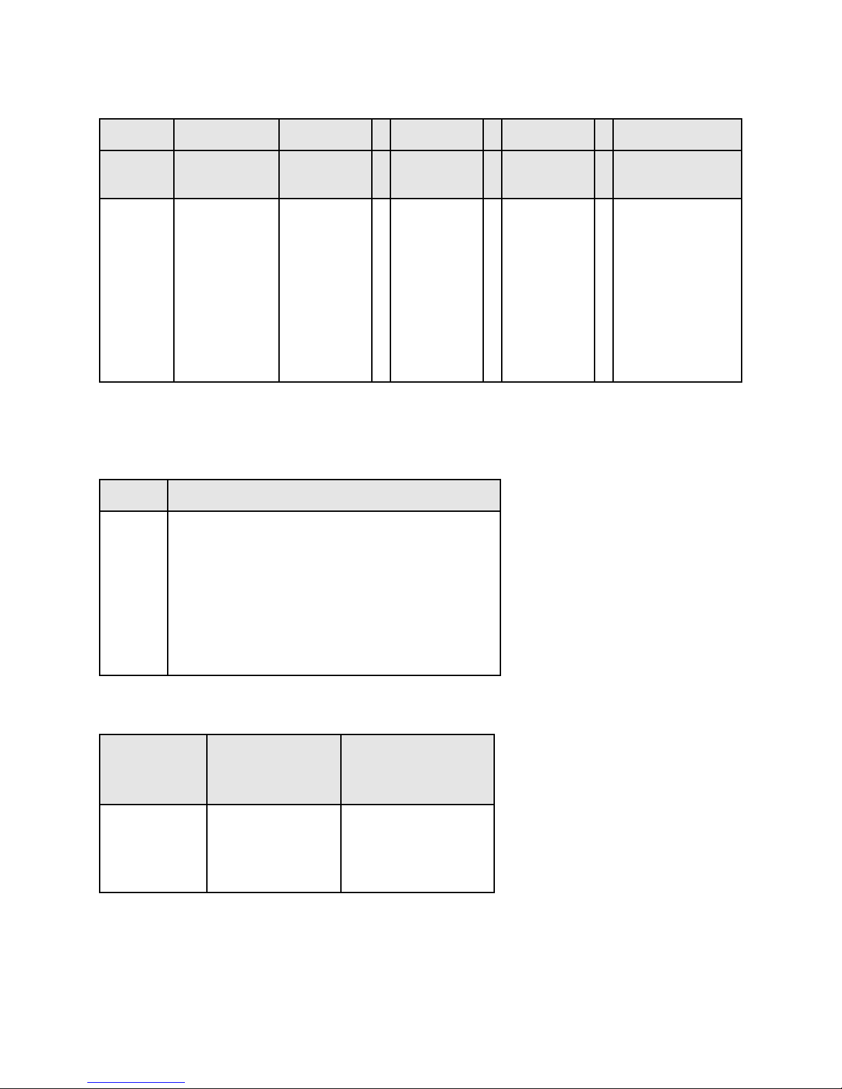
Table 1.2 MODEL ORDERING SYSTEM – Example XR500-16/208+WC+LXI
XR D 500 - 16 / 208 + WC+LXI
SERIES
NAME
XR
PQ
TS
MS
FRONT
PANEL
A: Analog
D: Digital
C: Computer
Blank: XR
OUTPUT
VOLTAGE
See Tables
1.11 and
greater
OUTPUT
CURRENT
See Tables
1.11 and
greater
MT
Note:
1) Multiple options can be specified as indicated.
Table 1.3 OPTIONS
TERM DEFINITION
EMI
WC
HS
LXI
GPIB
USB
RS485
EW
EMI Filter
Water Cooling
High-Slew Rate
LXI TCP/IP Ethernet Interface (Internal)
IEEE488.2 GPIB Interface (Internal)
USB Interface (External)
RS485 Interface (External)
Extended Warranty
INPUT
VOLTAGE OPTIONS
208 SP
See Table 1.3
240 SP
208
240
380
415
440
480
Table 1.4 SIZE AND WEIGHT MATRIX
POWER
kW
2.0
4.0
6.0
8.0
SIZE
H”xW”xD”
3½x19x24
3½x19x24
3½x19x24
3½x19x24
WEIGHT
LBS
45
47
48
48
9
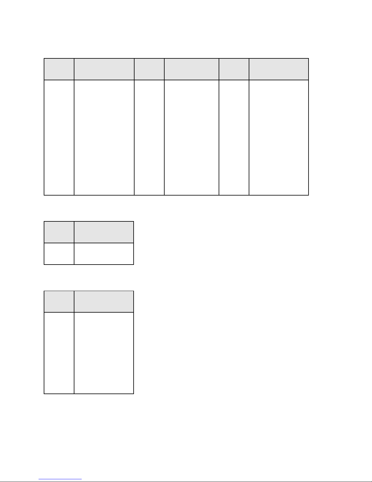
Table 1.5 TERMINAL DEFINITIONS FOR CONNECTOR JS1, REMOTE
INTERFACE
TERM PARAMETER TERM PARAMETER TERM PARAMETER
1
REF GND
2
REF GND
3
VREF EXT
4
TVREF EXT
5
VO2
6
+2.5V REF CAL
7
GND
8
POWER
9
THERMAL
10
INTERLOCK
11
CUR CTL
12
STANDBY/ALM
13
ALM
14
EXT CTL
15
RESERVE
16
RESERVE
17
START
18
CLEAR
19
STOP
20
REF GND
21
+10V REF
22
IREF EXT
23
TIREF EXT
24
IO2
25
VMOD
26
+5V
27
PGM LINE
28
STANDBY
29
PHASE LOSS
30
VOLT CTL
31
RESERVE
32
OCT
33
INT CTL
34
OVT
35
RESERVE
36
RESERVE
37
INTERLOCK
SET
Table 1.6 TERMINAL DEFINITIONS FOR CONNECTOR JS2, REMOTE SENSE
TERM PARAMETER
12VO1REM-
VO1REM+
Table 1.7 TERMINAL DEFINITIONS FOR CONNECTOR JS3, RS232
TERM PARAMETER
1
NC
2
RX
3
TX
4
DTR
5
GND
6
DSR
7
RTS
8
CTS
9
NC
10

Table 1.8 TERMINAL DEFINITIONS FOR CONNECTOR JS4, IEEE-488
TERM PARAMETER TERM PARAMETER
1
2
3
4
5
6
7
8
9
10
11
12
DIO1/Data line
DIO2/Data line
DIO3/Data line
DIO4/Data line
EOI/End or Identify
DAV/Data Valid
NRFD/Not Ready For Data
NDAC/Not Data Accepted
IFC/Interface Clear
SRQ/Service Request
ATN/Attention
Shield
13
14
15
16
17
18
19
20
21
22
23
24
DIO5/Data line
DIO6/Data line
DIO7/Data line
DIO8/Data line
REN/Remote Enable
DAV/Gnd
NRFD/Gnd
NDAC/Gnd
IFC/Gnd
SRQ/Gnd
ATN/Gnd
Ground
Table 1.9 TERMINAL DEFINITIONS FOR CONNECTOR JS5, ETHERNET
TERM PARAMETER
1
TX+
2
TX-
3
RX+
4
NC
5
NC
6
RX-
7
NC
8
NC
11

Table 1.10 OPTIONAL HIGH-SLEW OUTPUT PARAMETERS
OUTPUT
VOLTAGE
RANGE
Vdc
5
10-16
20
32
40-80
100-400
500
600
800
1000
OUTPUT
POWER
RANGE
kW
2 - 8
OUTPUT
CAPACITANCEμFRIPPLE
Vrms
13200
4080
2340
1170
240
160
80
56
56
52
.50
.50
.70
1.4
1.5
1.6
2.1
2.3
2.5
3.0
12

Table 1.11 2 KW MODELS AND RATINGS
MODEL
XR5-375
XR10-200
XR16-125
XR20-100
XR32-62
XR40-50
XR50-40
XR80-25
XR100-20
XR125-16
XR160-12
XR200-10
XR250-8.0
XR375-5.3
XR400-5.0
XR500-4.0
XR600-3.3
XR800-2.5
XR1000-2.0
VOLTS
Vdc
10
16
20
32
40
50
80
100
125
160
200
250
375
400
500
600
800
1000
AMPS
Adc
5
375
200
125
100
62
50
40
25
20
16
12
10
8.0
5.3
5.0
4.0
3.3
2.5
2.0
RIPPLE
mVrms
50
40
35
40
40
40
50
60
60
100
120
125
130
170
190
220
250
300
350
EFF
Notes:
1) Rating specified at 208, 380, and 440 V input.
2) Specifications subject to change without notice.
3) XR and XRC models all have identical ratings.
%
86
86
86
86
86
87
87
87
87
87
87
87
88
88
88
88
88
88
88
1φ UNITS
(Aac)
208/
240 V
18
18
18
18
18
18
18
18
18
18
18
18
18
18
18
18
18
18
18
INPUT CURRENT
3φ UNITS
(Aac)
208/
240 V
8
8
8
8
8
8
8
8
8
8
8
8
8
8
8
8
8
8
8
380/
415 V
5
5
5
5
5
5
5
5
5
5
5
5
5
5
5
5
5
5
5
440/
480 V
4
4
4
4
4
4
4
4
4
4
4
4
4
4
4
4
4
4
4
13

Table 1.12 4 KW MODELS AND RATINGS
MODEL
VOLTS
Vdc
AMPS
Adc
RIPPLE
mVrms
EFF
%
INPUT CURRENT (Aac)
208/240 V 380/415 V 440/480 V
XR10-375
XR16-250
XR20-200
XR32-124
XR40-100
XR50-80
XR80-50
XR100-40
XR125-32
XR160-24
XR200-20
XR250-16
XR375-10.6
XR400-10.0
XR500-8.0
XR600-6.6
XR800-5.0
XR1000-4.0
10
16
20
32
40
50
80
100
125
160
200
250
375
400
500
600
800
1000
375
250
200
124
100
80
50
40
32
24
20
16
10.6
10.0
8.0
6.6
5.0
4.0
40
35
40
40
40
50
60
60
100
120
125
130
170
190
220
250
300
350
Notes:
1) Rating specified at 208, 380, and 440 V input.
2) Specifications subject to change without notice.
3) XR and XRC models all have identical ratings.
86
86
86
86
87
87
87
87
87
87
87
88
88
88
88
88
88
88
15
15
15
15
15
15
15
15
14
14
14
14
14
14
14
14
14
14
9
9
9
9
9
9
9
9
9
9
9
9
9
9
9
9
9
9
8
8
8
8
8
8
8
8
8
8
8
8
8
8
8
8
8
8
14

Table 1.13 6 KW MODELS AND RATINGS
MODEL
VOLTS
Vdc
AMPS
Adc
RIPPLE
mVrms
EFF
%
INPUT CURRENT (Aac)
208/240 V 380/415 V 440/480 V
XR16-375
XR20-300
XR32-186
XR40-150
XR50-120
XR80-75
XR100-60
XR125-48
XR160-36
XR200-30
XR250-24
XR375-15.9
XR400-15.0
XR500-12
XR600-9.9
XR800-7.5
XR1000-6.0
16
20
32
40
50
80
100
125
160
200
250
375
400
500
600
800
1000
375
300
186
150
120
75
60
48
36
30
24
15.9
15.0
12.0
9.9
7.5
6.0
35
40
40
40
50
60
60
100
120
125
130
170
190
220
250
300
350
Notes:
1) Rating specified at 208, 380, and 440 V input.
2) Specifications subject to change without notice.
3) XR and XRC models all have identical ratings.
86
86
86
87
87
87
87
87
87
87
88
88
88
88
88
88
88
22
22
22
22
22
22
22
21
21
21
21
21
21
21
21
21
21
13
13
13
13
13
13
13
13
13
13
13
13
13
13
13
13
13
11
11
11
11
11
11
11
11
11
11
11
11
11
11
11
11
11
15

Table 1.14 8 KW MODELS AND RATINGS
MODEL
VOLTS
Vdc
AMPS
Adc
RIPPLE
mVrms
EFF
%
INPUT CURRENT (Aac)
208/240 V 380/415 V 440/480 V
XR20-375
XR32-250
XR40-200
XR50-160
XR80-100
XR100-80
XR125-64
XR160-50
XR200-40
XR250-32
XR375-21.3
XR400-20.0
XR500-16.0
XR600-13.3
XR800-10.0
XR1000-8.0
20
32
40
50
80
100
125
160
200
250
375
400
500
600
800
1000
375
250
200
160
100
80
64
50
40
32
21.3
20.0
16.0
13.3
10.0
8.0
60
60
60
70
80
80
120
125
120
140
200
220
240
280
320
380
Notes:
1) Rating specified at 208, 380, and 440 V input.
2) Specifications subject to change without notice.
3) XR and XRC models all have identical ratings.
86
86
87
87
87
87
87
87
87
88
88
88
88
88
88
88
29
29
29
29
29
29
28
28
28
28
28
28
28
28
28
28
17
17
17
17
17
17
17
17
17
17
17
17
17
17
17
17
15
15
15
15
15
15
15
15
15
15
15
15
15
15
15
15
16
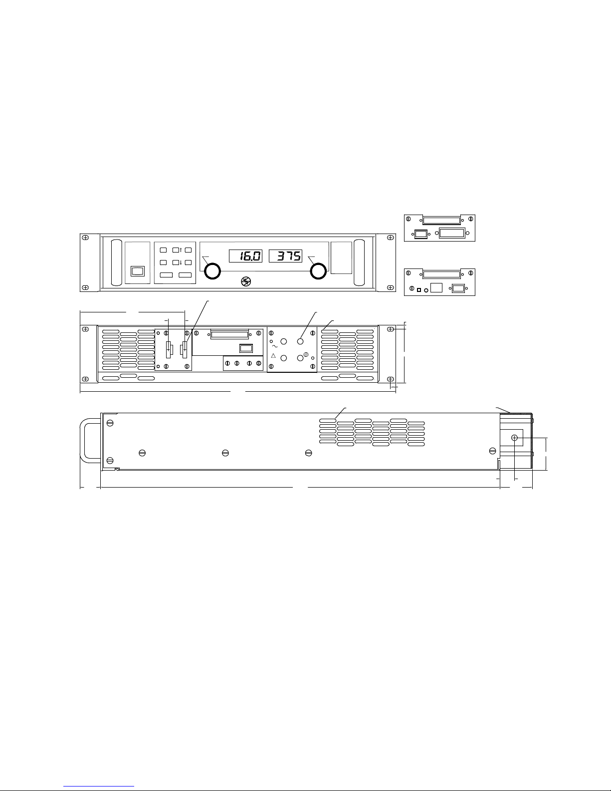
Figure 1.2 XR Series package drawing with XR Version front panel
1.250
JS2
12
OCTOVTTHLPHLPGLLOC
CTLCTL
REM SEN
INT CT L
EXT CTL
ROTARY
EXT PGM
REMOTE
POWER
STANDBY MENU V/IDIS CLEAR
ITEM TRIPDIS ENTER
START STOP
CURRENTVOLTAGE
DC VOLTAGE DCCURRE NT
CONFIGURATON
MODE
PWR
ELECTRONICS
M
AGNA-POWER
B
3
INPUT
!
OUTPUT
NEG
A
CGND
POS
JS1
JS3
24.000
0.234
3.469
0.328
19.000
1.000
6.312
0.875
1.966
AIR INTAKE BOTH SIDES
0.250X1.000 SILVER PLATED COPPER BUS,
3/8-16 THREADED INSERT, QTY 2
AIR EXHAUST, BOTH SIDES
10-32 THEADED INSERTS, QTY 4
FRONT PANEL
REAR P AN E L
SIDE PANEL
OPTIONAL IEEE-488
INTERFACE
OPTIONAL ETHERNET
INTERFACE
JS1
JS5
JS3
RST LAN
JS1
JS4JS3
1.937
PROTECTIVESHIELD
17
2.0 INSTALLATION AND POWER ON CHECK
XR Series power supplies are intended for rack mount installations only and are designed to fit
in standard 19" equipment racks. Additional support, other than that provided by the front panel,
is required. Angle slides or cross beam supports securely fastened to the rack are recommended
for supporting the weight of the power supply. The unit should be horizontally mounted.
Caution: The power supply is too heavy for one person to safely lift and mount.
To avoid injury, ask a co-worker for assistance.
2.1 Cooling
Each power supply enclosure is cooled by suitable blowers exhausting warm air to the rear of the
cabinet. Fresh air intake is from the sides of the cabinet allowing two or more XR Series
supplies to be stacked. Equipment racks should be equipped with fans or blowers to remove heat
generated by the power supplies. The manufacturer recommends fresh air intake at the bottom
of the cabinet and exhaust at the top. Fans and blowers should be rated at 300 CFM for each XR
Series supply.
Caution: blocking ventilation will cause the power supply to overheat.
2.2 AC Input Connections
Caution: disconnect AC power from the mains before attempting any
installation procedure.
Caution: a safety ground wire must be connected to the unit as indicated by
the protective ground symbol at the rear of the power supply.
AC power is wired to the power supply by attaching three cables plus ground for 3-phase
installations and two cables and ground for single phase installations. The manufacture
recommends cables, as specified in Tables 2.1 or 2.2, be crimped to ring terminals and securely
fastened to the studs at the rear of the power supply. After connections are made, screw the four
standoffs into the back panel and place the protective shield over the connections.
18
 Loading...