

Page 1
Order from: C A Briggs Company; 622 Mary Street; Suite 101 - Warminster, PA 18974
Phone: 267-673-8117 - 800-352-6265 - Fax: 267-673-8118; E-Mail: [email protected] - www.cabriggs.com
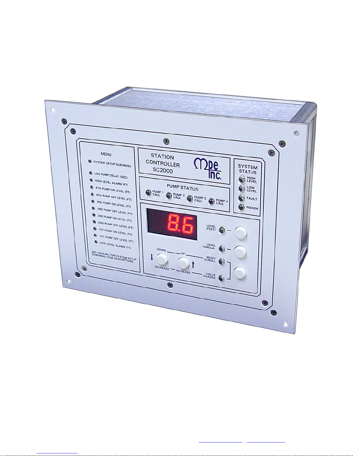
SC2000
SC2000
SC2000SC2000
INSTRUCTION MANUAL
INSTRUCTION MANUAL
INSTRUCTION MANUALINSTRUCTION MANUAL
M
MOTOR
OTOR
MM
OTOROTOR
2464 Vulcan Road
Apopka, Florida 32703
Operating Program Revision: 11
P
PROTECTION
PP
ROTECTION
ROTECTIONROTECTION
E
ELECTRONICS, INC.
LECTRONICS, INC.
EE
LECTRONICS, INC.LECTRONICS, INC.
Phone:
Website:
(407) 299-3825
www.mpelectronics.com
Revision Date: 4-17-14
Page 2
STATION CONTROLLER SC2000
• Simplex, Duplex, Triplex, or Quadraplex Liquid Level Control
• Pump Down (Empty a Tank) or Pump Up (Fill a Tank)
• Fixed or Variable Speed Control
• Where Connection to a SCADA System is Required
STANDARD FEATURES
• All Setup Parameters Values may be viewed or changed from the
front of the unit
• Level Input Source - Menu Selectable:
- Analog Level Input [4-20mA from Pressure Transducer]
- Level Probe [Conductance Probe with 10 Electrodes]
• Regulated +20VDC power for Analog Level Input
• RS-232 Serial Port with Modbus RTU Protocol
• High and Low Level Alarm Relays and Alarm Indication
• Adjustable Lag Pump(s) Delay
• Alternation Schemes - Menu Selectable:
- Standard Alternation
- Pump 1 Always Lead - Stays On with other Pumps
- Pump 1 Always Lead - Turns Off with other Pumps On
- Split Alternation - Pumps 1&2, and Pumps 3&4
- Fixed Sequence - Pump 1 Always Lead
- Stepped On/Off - Only One Pump Runs at a Time
Alternator Logic Skips Disabled Pumps
First On - First Off or First On - Last Off Alternation
• Level Simulation (Automatically ends after 1 minute)
• Security Code Protected Parameter Setup
• 18 Discrete Inputs programmable for the following functions:
- Pump disable with HOA in OFF, or pump fault
- External Lead Pump Selector Switch
- All pump disable - for connection to Phase Monitor
- Limit number of pumps called while on emergency power
- Alternation by External Time Clock
- Freeze wet well level during a bubbler tube purge
- Call pump last
- Float switch backup
- Low Level Pump Cutoff
- Start Flush Cycle
- A variety of SCADA functions
Status of Discrete Inputs may be viewed from front of Controller
• Backup Control, and High & Low Alarms using a Level Probe
• Output Relays may be programmed for control through SCADA
• Automatic Flush Cycle to reduce sludge build up
• Flow Calculator that provides the following Flow Data:
- Latest Inflow Rate
- Average Daily Inflow Total (Average of Last 7 Days)
- Pump Outflow Rate (Latest for Each Pump)
OPTIONAL FEATURES
• Up to four Isolated 4-20mA Analog Outputs that may be used for
VFD speed control or for sending out a copy of the Level Input
• Up to four Isolated 4-20mA Auxiliary Analog Inputs that may be
used to collect analog data for SCADA
• 4-20mA Analog Level Input may be ordered as an Isolated Input
• Ethernet Port with the following protocols:
Modbus TCP or Modbus RTU
SPECIFICATIONS APPLICATIONS
• Input Power: 120 VAC ±10%, 13 VA max
• External Dimensions: 6.9” x 8.5” x 4.9”
• Agency Approvals: UL 508, CAN/CSA
• Ambient Operating Temperature:
Without Analog Outputs:
-20°C to +65°C (-4°F to +149°F)
With Analog Outputs:
-20°C to +50°C (-4°F to +122°F)
• Level Display: 3 Digit, 7 Segment LED
• Level Display Range: 0 - 999 feet
(Decimal Point Position is Selectable)
• Indicators: LED
• Color: White with Blue Lettering
• Relays: 6A @ 250VAC
• Analog Level Input: 4-20mA, 250Ω Load,
Transient Protected
• Level Probe Inputs: ±8V, 60Hz Square Wave
±0.8mA max, Transient Protected
• Discrete Inputs: 24VDC, Transient Protected
• Power for Discrete Inputs: Unregulated
+24VDC, Transient Protected
• Power for Analog Level Input: Regulated
+20VDC ±1V, Transient Protected
• Analog Outputs: Isolated 4-20mA
Maximum Load Resistance: 600Ω
• Auxiliary Analog Inputs: Isolated 4-20mA,
250Ω Load, Transient Protected
ORDERING INFORMATION
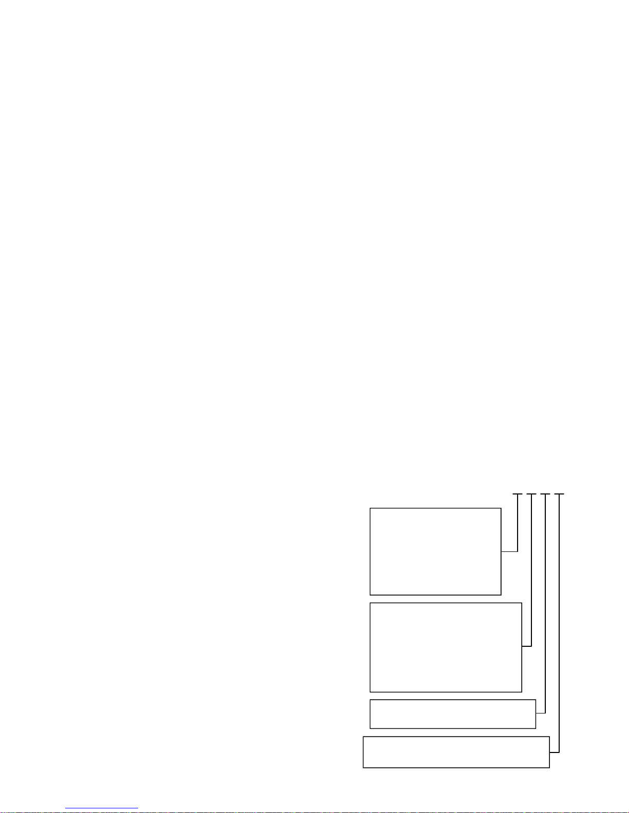
Part Number: SC2000 - X X X X
Number of Optional
Analog Outputs:
0 = Zero Analog Outputs
1 = One Analog Output
2 = Two Analog Outputs
3 = Three Analog Outputs
4 = Four Analog Outputs
Number of Optional
Auxiliary Analog Inputs:
0 = Zero Auxiliary Analog Inputs
1 = One Auxiliary Analog Input
2 = Two Auxiliary Analog Inputs
3 = Three Auxiliary Analog Inputs
4 = Four Auxiliary Analog Inputs
Blank = RS232 Port
E = RS232 Port & Ethernet Port
Blank = Non-Isolated Analog Level Input
S = Isolated Analog Level Input
1
Page 3
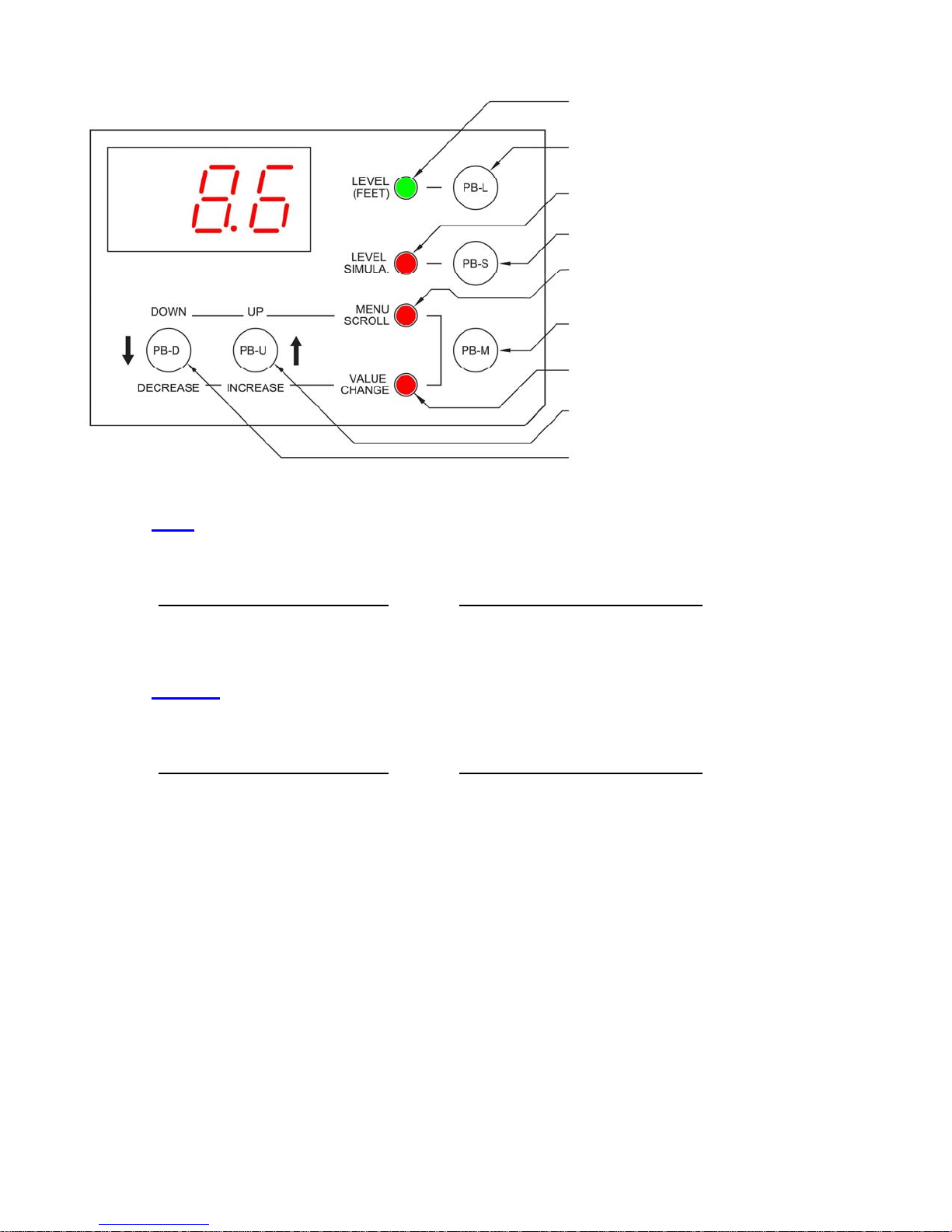
OPERATOR INTERFACE FUNCTIONS
Note: There is a 4 second Delay on Changing Parameter Values.
On when Display Shows the Wet Well Level
Press to Display Wet Well Level
On when in Level Simulation Mode
Press to Enter the Level Simulation Mode
On when in Menu Scroll Mode
Press to Change Function of the
Up/Down Push-Buttons
On when in Value Change Mode
Press to Scroll Up the Menu, or to
Increase Parameter Value
Press to Scroll Down the Menu, or to
Decrease Parameter Value
How to View a Setup Parameter Value
1. Press push-button PB-M until the Menu Scroll Mode indicator comes on.
2. Press push-button PB-D and PB-U as needed to arrive at the Parameter you wish to view.
3.
Parameters Shown on Front of Controller:
The value of the Parameter is displayed
whenever the indicator next to the Parameter label is on.
Parameters in the System Setup Sub-Menu:
The value of a Parameter in the System Setup Sub-Menu may be
viewed by using the push-button PB-M to toggle from the Parameter
number (P.13, for example) to the Parameter value.
How to Change a Setup Parameter Value
1. Press push-button PB-M until the Menu Scroll mode indicator comes on.
2. Press push-button PB-D and PB-U as needed to arrive at the Parameter you wish to change.
3.
4. Press and hold for 4 seconds, either push-button PB-D or PB-U, to change the Parameter to the desired new value.
(If the Parameter values will not change, they may be locked. See directions below to un-lock Parameters.)
5. Press push-button PB-M or PB-L to exit the Value Change mode.
Parameters Shown on Front of Controller:
Press push-button PB-M until the Value
Change indicator comes on.
Parameters in the System Setup Sub-Menu:
Press push-button PB-M until the Value Change indicator comes
on. The current value of the Parameter will then be displayed.
How to Simulate Levels
1. Press push-button PB-S.
Note: The Simulation starts from the actual level displayed prior to entering the Level Simulation mode.
2. Press push-button PB-D or PB-U as needed to change the simulated level.
3. To end the level simulation press push-button PB-L.
Note: If you do not exit the Level Simulation mode, normal operation will resume automatically 60 seconds after the
last time the PB-U, PB-D, or PB-S push-buttons were pressed.
How to Enter the Security Code
1. Press the push-button PB-M until the Menu Scroll mode indicator comes on.
2. Press push-button PB-U until the display reads SEC.
3. Press push-button PB-M to change to the Value Change mode.
4. Press and hold for 4 seconds, either push-button PB-D or PB-U, to change the value displayed, to that of the correct
security code.
2
Page 4
MENU - SYSTEM SETUP
Parameter
-
-
-
-
-
-
-
-
-
-
-
SEC
Default
Value
2.0 feet
3.0 feet 1st Pump Off Level SCADA Register 40013 Range: 0.2 - 99.9 feet
6.0 feet 1st Pump On Level SCADA Register 40012 Range: 0.2 - 99.9 feet
4.0 feet 2nd Pump Off Level SCADA Register 40015 Range: 0.2 - 99.9 feet
7.0 feet 2nd Pump On Level SCADA Register 40014 Range: 0.2 - 99.9 feet
4.5 feet 3rd Pump Off Level SCADA Register 40017 Range: 0.2 - 99.9 feet
8.0 feet 3rd Pump On Level SCADA Register 40016 Range: 0.2 - 99.9 feet
5.0 feet 4th Pump Off Level SCADA Register 40019 Range: 0.2 - 99.9 feet
9.0 feet 4th Pump On Level SCADA Register 40018 Range: 0.2 - 99.9 feet
10.0 feet High Level Alarm SCADA Register 40020 Range: 0.5 - 99.9 feet
5 sec. Lag Pump(s) Delay Range: 1 - 100 seconds
0
Current
Value Setting Definitions
All Level Settings Have the Decimal Point Artificially Inserted Based on Parameter P.36.
Low Level Alarm SCADA Register 40021 Range: 0.1 - 99.9 feet
Note: To Disable Alarm see Parameter P.50.
Security Code - Enter Your Security Code Here to Allow Parameters to be
Changed. Change to other Number to Re-lock All Parameters.
Note: The Security Code may be Customized using Parameter P.26. See Page 2.
P.13
P.14
4
4
Number of Pumps Present See Page 9.
1 = 1 Pump 2 = 2 Pumps 3 = 3 Pumps 4 = 4 Pumps
Number of Pumps Allowed to Run at the Same Time See Page 9.
1 = 1 Pump 2 = 2 Pumps 3 = 3 Pumps 4 = 4 Pumps
Number of Pumps Allowed to Run On Generator See Page 9.
P.15
4
1 = 1 Pump 2 = 2 Pumps 3 = 3 Pumps 4 = 4 Pumps
Note: Must Connect Transfer Switch Contacts to Discrete Input Programmed for Function 7.
Alternator Sequence Mode
1 = Standard Alternation See Page 11.
2 = Pump 1 Always Lead - Stays On With Other Pumps See Page 11.
P.16
P.17
P.18
1
2
1
3 = Pump 1 Always Lead - Turns Off With Other Pumps See Page 12.
4 = Split Alternation - Pumps 1&2, and Pumps 3&4 See Page 12.
5 = Fixed Sequence - Pump 1 Always Lead See Page 13.
6 = Stepped On/Off - Only One Pump Runs at a Time See Page 13.
Pump Stop Mode See Page 10.
1 = First On Last Off 2 = First On First Off
Automatic Alternation See Page 10.
1 = Enabled 2 = Disabled
Pump Up or Down Mode
P.19
1
1 = Pump Down - Empty a Tank 2 = Pump Up - Fill a Tank
Note: When Parameter P.19 is Changed New Default Level Parameter Values will be loaded.
P.20 - P.23 - VFD Speed Control Setup See Page 21.
3
Page 5
See Page 25.
See Page 25.
See Page 10.
See Page 10.
MENU - SYSTEM SETUP
Parameter
P.24
P.25
Default
Value
11.5 feet
0.0 feet
Current
Value
All Level Settings Have the Decimal Point Artificially Inserted Based on Parameter P.36.
Setting Definitions
Level Input Calibration - Span Range: 0.9 - 99.9 feet See Page 20.
Notes:
1. 20mA is Typically Applied to the Analog Input while Setting the Span.
2. Parameter P.24 Shows the Wet Well Level, while allowing the Up & Down Push-buttons to
Change the Internal Number used to Calculate the Displayed Level.
3. When Controller is set to Operate using a Level Probe, Parameter P.24 shows “77.7”.
Level Input Calibration - Zero
Notes:
1. 4.0mA is Typically Applied to the Analog Input while Setting the Zero.
2. Parameter P.25 Shows the Wet Well Level, while allowing the Up & Down Push-buttons to
Change the Internal Number used to Zero the Displayed Level.
3. When Controller is set to Operate using a Level Probe, Parameter P.25 shows “77.7”.
See Page 20.
Security Code Setup Parameter - Establishes What Value Will Be Accepted
as the Security Code at Parameter SEC. Range: 0 - 255
P.26
P.28
0
1 Slave Address
Notes:
1. To Change Parameter P.26, the Current Security Code Must First be Entered into SEC.
2. When You Change Parameter P.26 and Exit the Value Change Mode Parameter, P.26
Will No Longer Be Viewable, Until You Enter the New Security Code into Parameter SEC.
3. If You Forget Your Security Code, Consult the Factory for the Master Security Code.
P.29 - P.32 - RS232 Serial Port Setup See Page 26.
P.33
P.35
P.36
P.37
P.38
P.39
1 Register Access Mode
Stop Pump Delay Range: 1 - 100 seconds
1 sec.
1
1 min.
1 min.
0
Note: This is the Time Period that the Wet Well Level Must Remain At or Below (At or Above for
Pump Up P.19 = 2) the Respective OFF Level Setting in order to Turn Off a Pump.
Display Decimal Point Position
0 = No Decimal Point 1 = XX.X 2 = X.XX
Pump Re-enable Delay after Float Backup Low Level (High Level)
Notes: Range: 1 - 255 minutes
1. Pump Down (Parameter P.19 = 1) - Delay Starts when the Low Level Float Input Opens.
2. Pump Up (Parameter P.19 = 2) - Delay Starts when the High Level Float Input Opens.
Delay Canceling Remote Control Commands
Notes: Range: 0 - 254 minutes
1. Delay Starts when Serial Communication is Lost.
2. To Allow all Remote Commands to Remain in Effect (Until Power Loss) Set P.38 = 255.
Forced Lead Pump Position SCADA Register 40022
0 = Normal Alternation 1(2,3,4) = Pump 1(2,3,4) as Lead
P.40 - P.43 - Flush Cycle Setup See Page 22.
P.44 - P.47 - Flow Calculator Setup See Pages 23 - 24.
P.49
240
P.50
P.51
FLC -
LFC -
oPr -
1
0
Analog Level Input - Signal Conditioning Control Range: 1 - 254
10 = Very Slow 100 = Slow 240 = Normal 250 = Fast
Low Level Alarm Mode 0 = Disabled 1 = Enabled
Note: Setting “0” Disables Low Level Alarms from the Analog Level Input or Level Probe Inputs.
Time Based Alternation Range: 1 - 255 1/6 hour
0 = Disabled 1 = 1/6 hour 6 = 1 hour 48 = 8 hours 144 = 24 hours
Fault Code SCADA Register 40047 See Fault Code Table on Pages 18 - 19.
Note: This Automatically Returns to Zero when the Fault Clears (Except for Faults 20-29).
Last Fault Code SCADA Register 40048 See Fault Code Table on Pages 18 - 19.
Note: This is a Copy of the Last Non-Zero Fault Code that was shown on Parameter FLC.
Operating Program Revision Number - Controller SCADA Register 40063
EPr -
Operating Program Revision Number - Ethernet Board
4
Page 6
MENU - SYSTEM SETUP
Parameter
F.01
F.02
F.03
F.04
F.05
F.06
F.07
F.08
F.09
F.10
F.11
F.12
F.13
F.14
F.15
F.16
F.17
F.18
Default
Value
10
11
12
13
14
15
16
17
18
Current
Value Setting Definitions
1
2
3
4
5
6
7
8
9
All Level Settings Have the Decimal Point Artificially Inserted Based on Parameter P.36.
Discrete Input 1
Function
Discrete Input 2
Function
Discrete Input 3
Function
Discrete Input 4
Function
Discrete Input 5
Function
Discrete Input 6
Function
Discrete Input 7
Function
Discrete Input 8
Function
Discrete Input 9
Function
Discrete Input 10
Function
Discrete Input 11
Function
Discrete Input 12
Function
Discrete Input 13
Function
Discrete Input 14
Function
Discrete Input 15
Function
Discrete Input 16
Function
Discrete Input 17
Function
Discrete Input 18
Function
Function of Input: Connect To:
0 = No Function
1 = Pump 1 Disable …….………...…………...…. HOA and Fault Logic
2 = Pump 2 Disable …….….....…..……….….….. HOA and Fault Logic
3 = Pump 3 Disable ………..……..…….…..…..... HOA and Fault Logic
4 = Pump 4 Disable …….….…..………….….….. HOA and Fault Logic
5 = Level Freeze ……………...………....…. Bubbler Tube Purge Logic
6 = External Alternation ………...……......………. External Time Clock
7 = On Generator ………………….……….. Automatic Transfer Switch
8 = All Pump Disable …………...…………...…………... Phase Monitor
9 = Sequence Input 1 ……....…..…… Lead Select Switch - 1 as Lead
10 = Sequence Input 2 ….…….........… Lead Select Switch - 2 as Lead
11 = Sequence Input 3 …...…...…….… Lead Select Switch - 3 as Lead
12 = Sequence Input 4 ….……......…… Lead Select Switch - 4 as Lead
13 = Call Pump 1 Last ……...…….………...…………..…. Logic Contact
14 = Call Pump 2 Last ……...……………....…………..…. Logic Contact
15 = Call Pump 3 Last …….…….……..…...…………..…. Logic Contact
16 = Call Pump 4 Last …….………….….....…………..…. Logic Contact
17 = Low Level Alarm ……..………..…..…….… Low Level Float Switch
18 = High Level Alarm …………………...…..… High Level Float Switch
19 = Telemetry E ………...…………………....……… Telemetry Contact
20 = Telemetry F …….………………….....…….…… Telemetry Contact
21 = Telemetry G ……..……………………........…… Telemetry Contact
22 = Telemetry H …………………………...………… Telemetry Contact
23 = Telemetry J ………………………….…..….…… Telemetry Contact
24 = Telemetry K ……………………………...……… Telemetry Contact
25 = Telemetry L ……………………….…..….……… Telemetry Contact
26 = Telemetry M ………………………..……….…… Telemetry Contact
27 = Telemetry A ………………………..….…….…… Telemetry Contact
28 = Telemetry B ……………………...….….…..…… Telemetry Contact
29 = Telemetry C ……….…………………...…...…… Telemetry Contact
30 = Telemetry D ………………………...…..……..… Telemetry Contact
31 = Normal Pump Operation Disable ......................…..
32 = Float Backup – Low Level .….………........ Low Level Float Switch
33 = Float Backup – Off Level ….……….….….... Off Level Float Switch
34 = Float Backup – 1ST
35 = Float Backup – 2ND On Level ……..... 2ND On Level Float Switch
36 = Float Backup – 3RD On Level ……..... 3RD On Level Float Switch
37 = Float Backup – 4TH On Level ……...... 4TH On Level Float Switch
38 = Float Backup – High Level .………...…..... High Level Float Switch
39 = Start Flush Cycle …………………...……...…. External Time Clock
Notes:
1. Function of Discrete Inputs may be set to “0” when Input is used
only to collect data for SCADA and no other Function is desired.
2. All Discrete Inputs may be read from SCADA Registers 40035 40037, regardless of the Function assigned to the Input.
3. See Pages 14 - 16 for description of each of the above Functions.
On Level ……...... 1ST On Level Float Switch
.. Fault Contact
F.19
F.20
F.21
F.22
1
12 in. Level Probe Electrode Spacing Range: 3 - 24 inches
0.0 feet
100
Level Input Source
1 = Analog Level Input (4-20mA) on J21
2 = Level Probe Input on J25
3 = Level Probe Input on J25 (Flashes Level Probe Electrode No. of Level Settings.)
4 = Remote Level Input (Follows the Level written to SCADA Register 40025.)
Note: Level Probe not suitable for applications measuring Storm Water or Well Water.
Level Offset Range: 0.0 - 5.0 feet
Note: This adds to the Level from the Analog Level Input or Level Probe Input.
Level Probe Sensitivity Range: 90 - 210
100 = Typical Sewage 150 = Light Sewage
Check value of Parameter L.10 with Electrode 10 covered, add 40 to it, and enter value for F.22.
Note: Level Probe not suitable for applications measuring Storm Water or Well Water.
5
Page 7
MENU - SYSTEM SETUP
Parameter
Default
Value
Current
Value Setting Definitions
F.23 1 Analog Output 1 Function
F.24 2 Analog Output 2 Function
F.25 3 Analog Output 3 Function
F.26 4 Analog Output 4 Function
HI Relay Output Function
F.31 1
0 = Disabled 1 = High Level Alarm 2 = Remote Control
Note: High Level indicator on front of unit will operate regardless of setting.
LO Relay Output Function
F.32 1
0 = Disabled 1 = Low Level Alarm 2 = Remote Control (SCADA Coil 26)
Note: Low Level indicator on front of unit will operate regardless of setting.
P1 Relay Output Function
F.33
1
0 = Disabled 1 = Pump 1 Call 2 = Remote Control (SCADA Coil 27)
Note: When set on “0” or “2” Pump 1 will be skipped over in all Alternation Sequence Modes.
P2 Relay Output Function
F.34 1
0 = Disabled 1 = Pump 2 Call 2 = Remote Control (SCADA Coil 28)
Note: When set on “0” or “2” Pump 2 will be skipped over in all Alternation Sequence Modes.
P3 Relay Output Function
F.35 1
0 = Disabled 1 = Pump 3 Call 2 = Remote Control (SCADA Coil 29)
Note: When set on “0” or “2” Pump 3 will be skipped over in all Alternation Sequence Modes.
1 = Pump 1 Speed (Active When Pump 1 is Called)
2 = Pump 2 Speed (Active When Pump 2 is Called)
3 = Pump 3 Speed (Active When Pump 3 is Called)
4 = Pump 4 Speed (Active When Pump 4 is Called)
5 = Speed Reference any Pump (Always Active)
6 = Copy of Wet Well Level
(SCADA Coil 25)
P4 Relay Output Function
F.36
E.01 - E.62
b.01 0
b.02 0
b.03 0
b.04 0
b.05 0
b.06 0
b.07 0
Notes For Level Probe Backup Functions: For status of Level Probe inputs see Coils 583 - 592 in SCADA Register 40037.
1. When the controller is set up to follow a 10 Electrode Conductance Level Probe as the primary level input source (Parameter F.19
= 2 or 3), the backup functions described here are not needed and will not operate.
2. If a Function (such as Pump Control – 4TH On Level) is not desired set the respective parameter equal to zero.
3. An effective Backup Pump Control would involve having a 3 point Level Probe placed high in the wet well. The Level Probe would
be connected to Connector J25 terminals 1, 2, and 3. The Off Level should be made to operate from the bottom Electrode by
setting Parameter b.02 = 3. The 1ST On Level should be set to operate from Electrode 2 by setting Parameter b.03 = 2. The
2ND On Level should be set to operate from Electrode 1 by setting Parameter b.04 = 1. If additional pumps are present set the
3RD On and 4TH On Levels, to operated from Electrode 1 by setting Parameter b.05 = 1, and b.06 = 1.
4. If a Backup High Level Alarm is desired, set Parameter b.07 to the number of the Electrode Input that the High Level Probe is connected to. This feature is for alarm and telemetry only and will not function as a redundant pump call. See SCADA notes page 32.
5. If a Backup Low Level Alarm is desired, set Parameter b.01 to the number of the Electrode Input that the Low Level Probe is connected to. This feature is for alarm and telemetry only and will not function as a redundant pump off. See SCADA notes page 33.
6. Whenever the Backup Pump Control is active the Fault indicator will be on and fault code of 30 will be present in Parameter FLC,
and set Coil 15 in SCADA Register 40001.
1
0 = Disabled 1 = Pump 4 Call 2 = Remote Control (SCADA Coil 30)
Note: When set on “0” or “2” Pump 4 will be skipped over in all Alternation Sequence Modes.
- Ethernet Port Setup See Page 27.
Level Probe Backup Functions
Low Level Alarm
Pump Control – Off Level
Pump Control – 1ST On Level
Pump Control – 2ND On Level
Pump Control – 3RD On Level
Pump Control – 4TH On Level
High Level Alarm
0 = Function Not Used
1 = Electrode Input 1 on Connector J25-1
2 = Electrode Input 2 on Connector J25-2
3 = Electrode Input 3 on Connector J25-3
4 = Electrode Input 4 on Connector J25-4
5 = Electrode Input 5 on Connector J25-5
6 = Electrode Input 6 on Connector J25-6
7 = Electrode Input 7 on Connector J25-7
8 = Electrode Input 8 on Connector J25-8
9 = Electrode Input 9 on Connector J25-9
10 = Electrode Input 10 on Connector J25-10
6
Page 8
MENU - DATA DISPLAY
Parameter Data Description
L.01
L.02
L.03
L.04
L.05
L.06
L.07
L.08
L.09
Electrode 1 Status Value
Electrode 2 Status Value
Electrode 3 Status Value
Electrode 4 Status Value
Electrode 5 Status Value
Electrode 6 Status Value
Electrode 7 Status Value
Electrode 8 Status Value
Electrode 9 Status Value
Level Probe Electrode Status Values
Normal Range when Un-Covered: 240 - 255
Normal Range when Covered by Typical Sewage: 55 - 70
Notes:
1. The Controller compares each of the Electrode Status Values with what is set on
Parameter F.22. When the value drops below the setting on Parameter F.22, the
Controller logic considers the Electrode to be covered by liquid.
2. Parameters L.01 - L.10 are also used to diagnose Out of Sequence Faults (Fault
Codes 21 - 29).
3. For the status of the Level Probe inputs see Coils 583 - 592 in SCADA Register
40037.
L.10
L.11
FLH
FLL
FdH
FdL
F1H
F1L
F2H
F2L
F3H
F3L
F4H
F4L
Electrode 10 Status Value
Level Probe Test Signal Status Normal Range: 230 - 254
Note: This is a Measure of the ±8V, 60Hz Square Wave Sent Out to Each Electrode to read the level. If the value is below
210, a malfunction has occurred in the circuit that provides the Square Wave used to read the level. In this case the wet
well level display will show zero, the Fault indicator will be turned on, and Fault Code 20 will be generated.
Flow Calculator - Latest Inflow Rate FLH , FLL Gallons Per Minute
See pages 18 - 19. SCADA Register 40080
Flow Calculator - Average Daily Inflow Total FdH , FdL Units set by Parameter P.45.
See pages 18 - 19. SCADA Register 40081
Flow Calculator - Pump 1 Outflow Rate F1H , F1L Gallons Per Minute
See pages 18 - 19. SCADA Register 40082
Flow Calculator - Pump 2 Outflow Rate F2H , F2L Gallons Per Minute
See pages 18 - 19. SCADA Register 40083
Flow Calculator - Pump 3 Outflow Rate F3H , F3L Gallons Per Minute
See pages 18 - 19. SCADA Register 40084
Flow Calculator - Pump 4 Outflow Rate F4H , F4L Gallons Per Minute
See pages 18 - 19. SCADA Register 40085
7
Page 9
MENU - DATA DISPLAY
Parameter Data Description
n.01
n.02
n.03
n.04
n.05
n.06
n.07
n.08
n.09
n.10
n.11
n.12
Discrete Input 1 Status
Discrete Input 2 Status
Discrete Input 3 Status
Discrete Input 4 Status
Discrete Input 5 Status
Discrete Input 6 Status
Discrete Input 7 Status
Discrete Input 8 Status
Discrete Input 9 Status
Discrete Input 10 Status
Discrete Input 11 Status
Discrete Input 12 Status
Discrete Input Status
0 = Input Open
1 = Input Closed
Notes:
1. Discrete Input Status is used when troubleshooting the
2. Discrete Input Status data may be read by SCADA at
wiring and logic connected to the Discrete Inputs.
Registers 40035 - 40037. See Page 29 .
n.13
n.14
n.15
n.16
n.17
n.18
n.19
n.20
n.21
n.22
d.01
d.02
d.03
d.04
Discrete Input 13 Status
Discrete Input 14 Status
Discrete Input 15 Status
Discrete Input 16 Status
Discrete Input 17 Status
Discrete Input 18 Status
Auxiliary Analog Input 1 Status
Auxiliary Analog Input 2 Status
Auxiliary Analog Input 3 Status
Auxiliary Analog Input 4 Status
Voltage of +5 Volt Power Supply SCADA Register 40049 Normal Range: 8.5V - 11.3V
Note: Voltage is measured ahead of Voltage Regulator.
Auxiliary Analog Input Status Range: 0 - 255
Where: 0 = 0.0 mA 51 = 4.0 mA 255 = 20 mA
Note: Auxiliary Analog Input data may be read by SCADA
in either an 8-Bit or 10-Bit format. See Page 30.
Voltage of +24 Volt Power Supply SCADA Register 40050 Normal Range: 21.1V - 25.5V
Pump 1 VFD Speed Reference (Percent of Full Speed, 0 - 100%) SCADA Register 40038
Pump 2 VFD Speed Reference (Percent of Full Speed, 0 - 100%) SCADA Register 40039
d.05
d.06
d.07
d.08
d.09
d.10-d.86
Pump 3 VFD Speed Reference (Percent of Full Speed, 0 - 100%) SCADA Register 40040
Pump 4 VFD Speed Reference (Percent of Full Speed, 0 - 100%) SCADA Register 40041
Serial Communication Activity Indicator See Page 34.
Serial Communication – Shows the Address of the Last Slave Polled by the Master See Page 34.
Serial Communication – Shows the Last Modbus Function Code Received See Page 34.
Serial Communication – Shows the Entire Rest of the Last Modbus Message Received
8
Page 10
PUMP CALL SEQUENCE - Setup Parameters
The following is a description of each of the Setup Parameters used to establish the Pump Call Sequence:
Note: Discrete Inputs programmed with Functions 1-4, 6-7, 9-12, and 13-16 are also available to establish or modify the
Pump Call Sequence. See the description of these Discrete Input Functions on pages 14-16.
Number of Pumps Present - Parameter P.13
This Parameter establishes how many pumps are available at the Lift Station to perform level control.
Simplex (1 pump) Duplex (2 pumps) Triplex (3 pumps) Quadraplex (4 pumps)
Default
Parameter
Value Setting Definitions
P.13
4
Number of Pumps Present
1 = 1 Pump 2 = 2 Pumps 3 = 3 Pumps 4 = 4 Pumps
Number of Pumps Allowed to Run at the Same Time - Parameter P.14
In cases where there is an inadequately sized discharge pipe, or inadequate electrical power, running all available
pumps at the same time may be a problem. This Parameter is used to set an upper limit on the number of pumps
called to run at the same time. If there is no need for this feature P.14 may be left on it’s default value of 4.
Default
Parameter
P.14
Value Setting Definitions
4
Number of Pumps Allowed to Run at the Same Time
1 = 1 Pump 2 = 2 Pumps 3 = 3 Pumps 4 = 4 Pumps
Number of Pumps Allowed to Run On Generator - Parameter P.15
In cases where the Emergency Generator is not sized large enough to run all the available pumps, this Parameter
is used to set an upper limit on the number of pumps called to run on the Generator. There must be a contact from
the Transfer Switch connected to one of the Controller’s Discrete Inputs and it must be programmed for Function 7.
If there is no need for this feature Parameter P.15 may be left on it’s default value of 4.
Default
Parameter
Value Setting Definitions
P.15
4
Alternator Sequence Mode - Parameter P.16
This Parameter is provided to allow the Controller to accommodate a variety of special sequence requirements.
Default
Parameter
P.16
Value Setting Definitions
1
Number of Pumps Allowed to Run On Generator
1 = 1 Pump 2 = 2 Pumps 3 = 3 Pumps 4 = 4 Pumps
Alternator Sequence Mode
1 = Standard Alternation See Page 11.
2 = Pump 1 Always Lead - Stays On With Other Pumps See Page 11.
3 = Pump 1 Always Lead - Turns Off With Other Pumps See Page 12.
4 = Split Alternation - Pumps 1&2, and Pumps 3&4 See Page 12.
5 = Fixed Sequence - Pump 1 Always Lead See Page 13.
6 = Stepped On/Off - Only One Pump Runs at a Time See Page 13.
9
Page 11
PUMP CALL SEQUENCE - Setup Parameters
Pump Stop Mode - Parameter P.17
This Parameter establishes which pump is the next one to be stopped, when there are two or more pumps on.
The Controller has a corresponding “Pump Off Level” setting for each of the “Pump On Level” settings. For the
“Pump Stop Mode” feature to operate, the “Pump Off Level” settings must be set on different levels. If all the
“Pump Off Level” settings are set on the same level it does not matter what Parameter P.17 is set on.
First On Last Off - In this mode, as the level reaches one of the “Pump Off Level” settings, the pump that was
most recently turned on is turned off, leaving the one that was call to run first still running.
First On First Off - In this mode, as the level reaches one of the “Pump Off Level” settings, the pump that was
most recently turned on is left on and the pump that has been on the longest is turned off. This results in a longer
cool down period for each pump between starts. This mode works the best in stations where one pump is required
to run for a long period of time, with an occasional need for an additional pump.
Default
Parameter
Value Setting Definitions
P.17
2 Pump Stop Mode 1 = First On Last Off 2 = First On First Off
Automatic Alternation - Parameter P.18
This Parameter is provided so that normal automatic alternation may be disabled (turned off). Typically, normal
alternation is disabled only in applications that have an external Time Clock used to alternated the pumps.
(The Time Clock would be connected to a Discrete Input programmed for “External Alternation” , Function 6.)
Default
Parameter
P.18
Value Setting Definitions
1 Automatic Alternation 1 = Enabled 2 = Disabled
Forced Lead Pump Position - Parameter P.39
This Parameter is provided so that a fixed sequence may be established with the selected pump always as lead.
For example setting Parameter P.39 on 1 will cause a fixed pump call sequence of 1-2-3-4. Parameter P.39
may also be changed by writing a 0,1,2,3 or 4 to SCADA Register 40022.
Default
Parameter
P.39
Value Setting Definitions
0
Forced Lead Pump Position SCADA Register 40022
0 = Normal Alternation 1(2,3,4) = Pump 1(2,3,4) as Lead
Time Based Alternation - Parameter P.51
This feature may be used to ensure that alternation periodically occurs even in applications that tend to run one
pump for a long period of time. The internal Time Clock starts and runs whenever at least one pump is called to
run. When it times out, it forces the alternation of the pumps and then resets the Time Clock. The Time Clock is
also reset each time a Normal Alternation Occurs.
Default
Parameter
P.51
Value Setting Definitions
0
Time Based Alternation Time Clock Range: 1 - 255 1/6 hour
0 = Disabled 1 = 1/6 hour 6 = 1 hour 48 = 8 hours 144 = 24 hours
10
Page 12
ALTERNATION SEQUENCE MODE
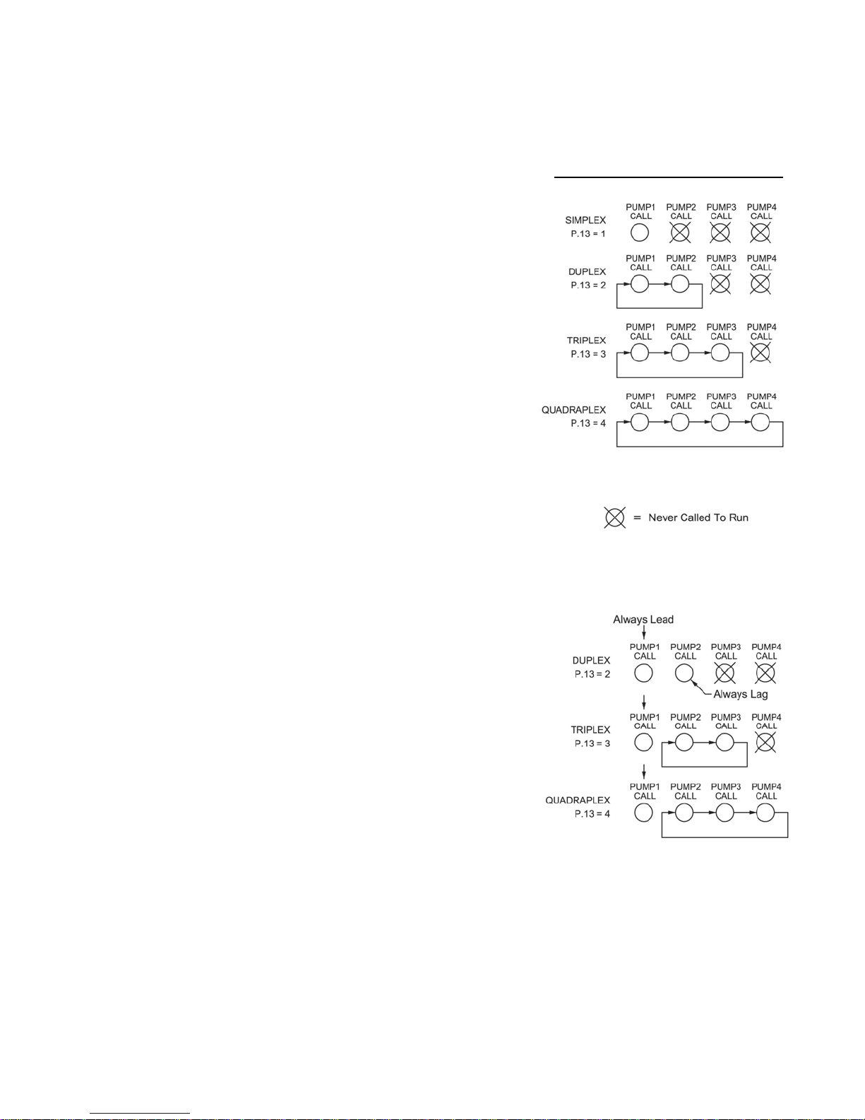
STANDARD ALTERNATION Parameter P.16 = 1
Notes:
1. Unless there is some special circumstance that requires a more complicated
pump call sequence, this is the sequence that should be used.
2. Parameter P.17 must be used to select either First On Last Off or First On
First Off.
3. Discrete Inputs programmed as Pump 1-4 Disable inputs may be used to
disable pumps.
4. Discrete Inputs programmed as Call Pump 1-4 Last inputs may be used to
assign pumps to standby status.
5. Discrete Inputs programmed as Sequence Inputs 1-4 may be used to set
the lead pump.
6. Parameter P.39 may be used to set the lead pump.
7. A Discrete Input programmed for External Alternation (Function 6) may be
used to force alternation. When this feature is used, Automatic Alternation
would normally be disabled by setting Parameter P.18 to Disabled.
8. If connected to a SCADA system, alternation may be initiated by momentarily setting Coil 136, or by forcing the lead pump by writing to Register 40022
(Same as Parameter P.39).
9. Parameter P.51 may be used to select and setup Time Based Alternation.
Movement of Lead Pump Upon Alternation
PUMP 1 ALWAYS LEAD
Stays On With Other Pumps Parameter P.16 = 2
Notes:
1. This sequence is used when it is required that pump 1 always be lead pump.
This sequence keeps pump 1 on, when the other pumps are called to run.
2. Parameter P.17 must be used to select either First On Last Off or First On
First Off.
3. Discrete Inputs programmed as Pump 1-4 Disable inputs may be used to
disable pumps.
4. Discrete Inputs programmed as Call Pump 1-4 Last inputs may be used to
assign pumps to standby status.
5. Discrete Inputs programmed as Sequence Inputs 1-4 may be used to set
the lead pump.
6. Parameter P.39 may be used to set the lead pump among pumps 2 - 4.
7. If pump 1 is disabled another pump will be called in its place.
8. A Discrete Input programmed for External Alternation (Function 6) may be
used to force alternation. When this feature is used, Automatic Alternation
would normally be disabled by setting Parameter P.18 to Disabled.
9. If connected to a SCADA system, alternation may be initiated by momentarily setting Coil 136, or by forcing the lag pump by writing to Register 40022
(Same as Parameter P.39).
10. Parameter P.51 may be used to select and setup Time Based Alternation.
11
Page 13
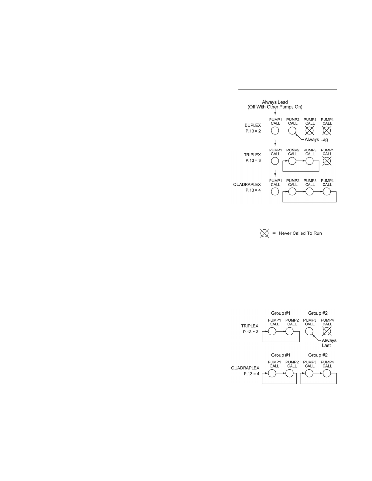
ALTERNATION SEQUENCE MODE
PUMP 1 ALWAYS LEAD
Turns Off With Other Pumps On
Notes:
1. This sequence is used when it is required that pump 1 always be lead, and
when it must be turned off when another pump(s) comes on. When a pump
from the second group is required, pump 1 is first turned off, then after the
Lag Pump Delay, the other pump is turned on.
2. For Triplex and Quadraplex applications Parameter P.17 must be used to
select either First On Last Off or First On First Off.
3. Discrete Inputs programmed as Pump 1-4 Disable inputs may be used to
disable pumps.
4. For Triplex and Quadraplex applications Discrete Inputs programmed as
Call Pump 2-4 Last inputs may be used to assign pumps to standby status.
5. For Triplex and Quadraplex applications Discrete Inputs programmed as
Sequence Inputs 2-4 may be used to set the lead pump.
6. For Triplex and Quadraplex applications Parameter P.39 may be used to set
the lead pump.
7. If pump 1 is disabled, another pump will Not be called in its place. The 1ST
Pump On/Off Level parameters are dedicated to pump 1 and will not call
another pump.
8. A Discrete Input programmed for External Alternation (Function 6) may be
used to force alternation. When this feature is used, Automatic Alternation
would normally be disabled by setting Parameter P.18 to Disabled.
9. If connected to a SCADA system, alternation may be initiated by momentarily setting Coil 136, or by forcing the lag pump by writing to Register 40022
(Same as Parameter P.39).
10. Parameter P.51 may be used to select and setup Time Based Alternation.
Parameter P.16 = 3
Movement of Lead Pump Upon Alternation
SPLIT ALTERNATION
Parameter P.16 = 4
Notes:
1. This sequence is used when it is required that pumps be alternated in two
separate groups.
2. Parameter P.17 must be used to select either First On Last Off or First On
First Off.
3. Discrete Inputs programmed as Pump 1-4 Disable inputs may be used to
disable pumps.
4. Discrete Inputs programmed as Call Pump 1-4 Last inputs may be used to
assign pumps to standby status.
5. Discrete Inputs programmed as Sequence Inputs 1-4 may be used to set the
lead pump.
6. Parameter P.39 may be used to set the lead pump of group #1.
7. If pumps from group 1 are disabled, then pumps in group #2 may be called
to take their place.
8. A Discrete Input programmed for External Alternation (Function 6) may be
used to force alternation of Group #1. When this feature is used, Automatic
Alternation would normally be disabled by setting Parameter P.18 to Disabled.
9. If connected to a SCADA system, alternation of Group #1 may be initiated
by momentarily setting Coil 136, or by forcing the lead pump position by
writing to Register 40022 (Same as Parameter P.39).
10. Parameter P.51 may be used to select and setup Time Based Alternation
of Group #1.
12
Page 14
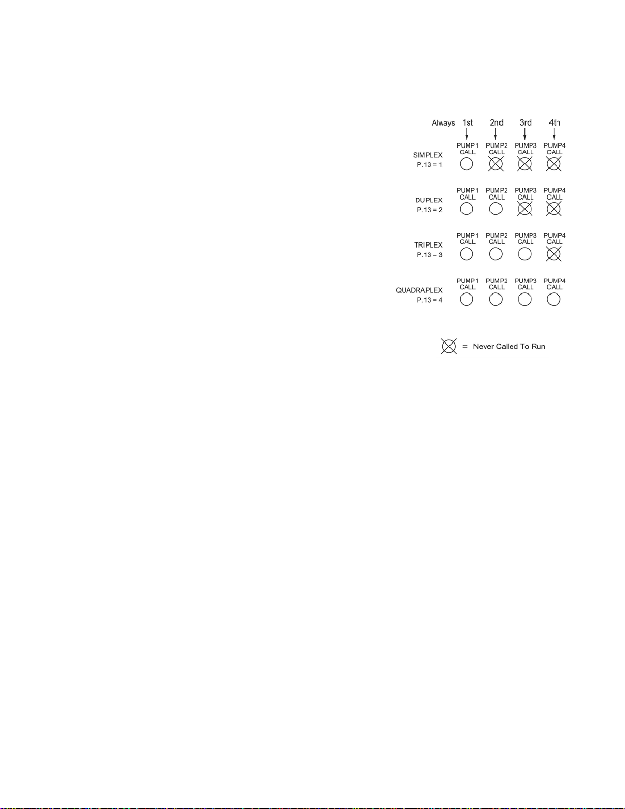
ALTERNATION SEQUENCE MODE
FIXED ALTERNATION Parameter P.16 = 5
Notes:
1. This sequence is used when no alternation is required and when pump 1
should normally be lead pump. Other pumps may be made lead by setting
Parameter P.39.
2. Discrete Inputs programmed as Pump 1-4 Disable inputs may be used to
disable pumps.
3. Discrete Inputs programmed as Call Pump 1-4 Last inputs may be used to
assign pumps to standby status.
4. Discrete Inputs programmed as Sequence Inputs 1-4 may be used to set the
lead pump.
5. Parameter P.39 may be used to set the lead pump.
6. The Pump Stop Mode (Parameter P.17) has no effect on this sequence.
7. Automatic Alternation Enable/Disable (Parameter P.18) has no effect on this
sequence.
8. The External Alternation feature will not function when using this sequence.
9. If connected to a SCADA system, the lead pump position may be set by
writing to Register 40022 (Same as Parameter P.39).
10. Time Based Alternation using Parameter P.51 will not function when using
this sequence.
STEPPED ON/OFF SEQUENCE
Only One Pump Runs at a Time Parameter P.16 = 6
Notes:
1. This sequence is used in stations where there is a significant difference in
the size of the pumps, and when only one pump is to be allowed to run at a
time. When there is a need for more pumping, the smaller pump is turned
off and the next larger pump is called to run. As the need for pumping decreases, the larger pump is turned off and a smaller pump is called to run in
its place (provided the Off Levels are staggered).
2. The Lag Pump Delay operates to give the check valve of the pump being
turned off time to close before another pump is called to run.
3. Discrete Inputs programmed as Pump 1-4 Disable inputs should be used to
disable pumps that are not able to run. It is critical that the largest pump in
the group, have some type of pump fault logic connected to the respective
Pump Disable discrete input.
4. Discrete Inputs programmed as Call Pump 1-4 Last will not function when
using this sequence.
5. Discrete Inputs programmed as Sequence Inputs 1-4 will not function when
using this sequence.
6. Parameter P.39 has no effect on this sequence.
7. The Pump Stop Mode (Parameter P.17) has no effect on this sequence.
8. Automatic Alternation Enable/Disable (Parameter P.18) has no effect on this
sequence.
9. The External Alternation feature will not function when using this sequence.
10. The On Generator (Parameter P.15) has no effect on this sequence.
11. Time Based Alternation using Parameter P.51 will not function when using
this sequence.
13
Page 15

DISCRETE INPUT FUNCTIONS
The following is a description of the Functions that may be assigned to the Discrete Inputs using Parameters F.01 - F.18:
Notes: 1. All Discrete Inputs are originally programmed with default Functions, but they may be changed at any time using
Pump 1 (2, 3, 4) Disable - Functions 1 - 4
Level Freeze - Function 5
Parameters F.01 - F.18.
2. Each of the Functions may only be assigned to one Discrete Input. If assigned to more than one input, the Fault
indicator will come on and Fault Code 8 will be generated.
When a Discrete Input programmed as a “Pump 1 (2, 3, 4) Disable” is closed, the respective pump will be disabled (not allowed to run) and skipped over in the pump call sequence. If the respective pump had been running
when the input closed, it would be turned off immediately.
Whenever a pump is disabled the next available pump is called in its place when needed. The one exception to
this, is the Alternation Sequence - Pump 1 Always Lead (Parameter P.16 = 3), where disabling pump 1 will not
result in another pump taking it’s place.
When a Discrete Input programmed for “Level Freeze” is first closed, the Wet Well Level is held steady or frozen
so that a bubbler system’s bubbler tube may be purge without causing the Level to jump up or down. The external
logic that performs the bubbler tube purge must provide the Discrete Input closure prior to a significant change in
the 4-20mA analog Level input. The Level Freeze logic keeps the Level frozen for 10 seconds and then releases
it, regardless of whether the Discrete Input had re-opened or not. It does not matter how long the input remains
closed, but it must be opened to reset the logic.
External Alternation - Function 6
Each time the Discrete Input programmed for “External Alternation“ transitions from open to closed, alternation of
the pumps will occur. It does not matter how long the input remains closed, but it must be opened to reset the
logic. If no pumps were running when the Discrete Input is closed, the alternation of the designated lead pump will
still occur. Typically this input is connected to contacts from an external Time Clock.
On Generator - Function 7
In cases where the Emergency Generator is not sized large enough to run all the available pumps, closing a Discrete Input programmed for “On Generator” will limit the number of pumps called to run to the number preset using Parameter P.15. Typically contacts from the Transfer Switch are connected to this input.
All Pump Disable - Function 8
When a Discrete Input programmed for “All Pump Disable” is closed, all the pumps are disabled (not allowed to
run), the Fault indicator will come on, the Power indicator will flash, and Fault Code 18 will be generated. This
Function also disables pump operation from Float Backup using Functions 32 - 38, or Level Probe Backup using
Parameters b.01 - b.07. The Discrete Input is typically connect to Phase Monitor contacts.
When the Discrete Input opens, the Lag Pump Delay must expire before the first pump is allowed to run. If any
additional pumps are required, the Lag Pump Delay must expire between each one called to run.
Sequence Input 1 (2, 3, 4) - Functions 9 - 12
When a Discrete Input programmed as a “Sequence Input 1 (2, 3, 4) ” is closed, it disables normal alternation and
forces one of the pumps to always be lead pump. For example, closing “Sequence Input 1” forces pump 1 to be
lead and sets the sequence of 1 - 2 - 3 - 4 (assuming Parameter P.16 = 1). See page 37 for connection diagrams.
14
Page 16

DISCRETE INPUT FUNCTIONS
Call Pump 1 (2, 3, 4) Last - Functions
When a Discrete Input programmed for “Call Pump 1 (2, 3, 4) Last” is closed, it assigns the respective pump to
standby status, where it will always be called to run last.
If more than one but not all of the pumps are assigned to standby status, they will all be available to run if needed,
but in a fixed order, and always after the pumps not assigned standby status.
If all the pumps are assigned to standby status, then alternation will occur normally, as though none of them were
assigned standby status.
Low Level Alarm - Function 17
When a Discrete Input programmed for “Low Level Alarm“ is closed, the Low Level indicator will come on and the
Low Level Alarm relay contacts will close. This Function is for alarm and indication only and will not disable pump
operation. Also see Function 32.
High Level Alarm - Function 18
When a Discrete Input programmed for “High Level Alarm“ is closed, the High Level indicator will come on and
the High Level Alarm relay contacts will close. This Function is for alarm and indication only and will not affect
pump operation. Also see Function 38.
Telemetry E - D - Functions 19 - 30
When the Discrete Input(s) programmed for “Telemetry E-D” are closed, no control Function in the Controller is
performed, only the status of the Discrete Inputs is placed in predetermined Coils in SCADA Registers 40001 and
40008. These Functions are use to assign any of the available Discrete Inputs to a specific Coil. See Page 28.
Normal Pump Operation Disable - Function 31
When a Discrete Input programmed for “Normal Pump Operation Disable” is closed, all the pumps are disabled
(not allowed to run), the Fault indicator will come on, and Fault Code 15 will be generated. However, this Function
does allow pump operation from Float Backup using Functions 32 - 38, or Level Probe Backup using Parameters
b.01 - b.07.
This Function is used when it is required that a backup system have complete control of the pumps. The Discrete
Input must be connected to contacts that closes when external logic determines that switching control of the
pumps to the backup system is necessary.
Float Backup - Low Level - Function 32
When a Discrete Input programmed for “Float Backup - Low Level“ is closed, the Low Level indicator will come on
and the Low Level Alarm relay contacts will close. Also see Function 17.
Pump Down Mode (Parameter P.19 = 1)
All pump operation will be disabled when the “Float Backup - Low Level“ input closes.
When the “Float Backup - Low Level“ input opens the “Pump Re-enable Delay” (set using Parameter P.37),
must expire before pump operation is allowed.
Pump Up Mode (Parameter P.19 = 2)
All available pumps will be called to run when the “Float Backup - Low Level“ input closes, assuming that the
“Float Backup - Off Level“ input is closed.
See Page 42.
15
Page 17

DISCRETE INPUT FUNCTIONS
Float Backup - Off Level - Function 33
When a Discrete Input programmed for “Float Backup - Off Level“ closes, the Float Backup logic will be armed
and made ready to latch in one pump call for each of the “Float Backup - 1st , 2nd, 3rd, 4th On Level“ inputs that
close.
As the “Float Backup - 1st , 2nd, 3rd, 4th On Level“ inputs open, the pump calls remain latched until the Off Level
input also opens, then the latch is broken on all the pump calls, and the pumps are turned off.
Note: For a two float backup system, the “Float Backup - 1st , 2nd, 3rd, 4th On Level“ inputs may be replaced
with the High Level input for the Pump Down mode, or the Low Level input for the Pump Up mode.
See Page 42.
Float Backup - 1st On Level - Function 34
When a Discrete Input programmed for “Float Backup - 1st On Level“ closes, the Float Backup logic will issue one
pump call assuming that the “Float Backup - Off Level“ is closed. See Page 42.
Float Backup - 2st On Level - Function 35
When a Discrete Input programmed for “Float Backup - 2nd On Level“ closes, the Float Backup logic will issue
one pump call assuming that the “Float Backup - Off Level“ is closed. See Page 42.
Float Backup - 3rd On Level - Function 36
When a Discrete Input programmed for “Float Backup - 3rd On Level“ closes, the Float Backup logic will issue
one pump call assuming that the “Float Backup - Off Level“ is closed. See Page 42.
Float Backup - 4th On Level - Function 37
When a Discrete Input programmed for “Float Backup - 4th On Level“ closes, the Float Backup logic will issue
one pump call assuming that the “Float Backup - Off Level“ is closed. See Page 42.
Float Backup - High Level - Function 38
When a Discrete Input programmed for “Float Backup - High Level“ is closed, the High Level indicator will come
on and the High Level Alarm relay contacts will close. Also see Function 18.
Pump Down Mode (Parameter P.19 = 1)
All available pumps will be called to run when the “Float Backup - High Level“ input closes, assuming that the
“Float Backup - Off Level“ input is closed.
Pump Up Mode (Parameter P.19 = 2)
All pump operation will be disabled when the “Float Backup - High Level“ input closes.
When the “Float Backup - High Level“ input opens the “Pump Re-enable Delay” (set using Parameter P.37),
must expire before pump operation is allowed.
See Page 42.
Start Flush Cycle - Function 39
When a Discrete Input programmed for “Start Flush Cycle“ closes, the Flush Cycle will start (assuming that the
Flush Cycle Mode Parameter P.40 = 2). It does not matter how long the input remains closed, but it must be
opened to reset the logic. Typically this input is connected to contacts from an external Time Clock. See Page 22.
16
Page 18

SYSTEM STATUS
High Level Alarm
• Upon a High Level Alarm, the indicator will come on and the relay contacts will close.
• A High Level Alarm is delayed for ten seconds after power is applied.
• The High Level Alarm relay contacts will be closed when there is no power on the controller.
• The moment electrical power is applied to the controller, the High Level Alarm relay contacts open.
• The High Level Alarm relay contacts will close if there is a complete failure of the controller.
• The High Level Alarm will be activated as the level rises to or above the High Level Alarm level setting.
• A High Level float will activate the alarm. The Discrete Input used must be assigned Function 18 or 38.
• A High Level from a Level Probe input will activate the alarm. See Parameter b.07.
• With the Level Input Source set for the Level Probe (Parameter F.19 = 2 or 3), if not already on, the High
Level Alarm will be activated when Electrode 1 is covered with liquid.
Low Level Alarm
• Upon a Low Level Alarm, the indicator will come on and the relay contacts will close.
• A Low Level Alarm is delayed for 90 seconds after power is applied.
• The Low Level Alarm relay contacts will be open when there is no power on the controller.
• The Low Level Alarm will be activated when the level is at or below the Low Level Alarm level setting.
• A Low Level float will activate the alarm. The Discrete Input used must be assigned Function 17 or 32.
• A Low Level from a Level Probe input will activate the alarm. See Parameter b.01.
• The Low Level Alarm will not function as a redundant pump off, except for the Low Level Alarm from
Float Backup using a Discrete Input programmed for Function 32, which will turn off the pumps.
• With the Level Input Source set for the Level Probe (Parameter F.19 = 2 or 3), if not already on, the Low
Level Alarm will be activated when Electrode 10 is uncovered, unless it is disabled using Parameter
P.50.
• Low Level Alarm operation may be disabled by setting Parameter P.50 = 0. This disables Low Level
Alarm operation from either the Analog Level Input (Parameter F.19 = 1) or from a Level Probe
(Parameter F.19 = 2 or 3). However, it will not disable alarm operation from a Low Level float input using
a Discrete Input (Function 17 or 32), or from the Backup Low Level Probe input (See Parameter b.01).
Power Indication
The Power indicator is normally on, but it will alternately flash with the Fault indicator, when the All Pump
Disable Discrete Input (Function 8) is closed. Fault Code Parameter FLC will also show Fault Code 18.
Fault Indication
The Fault indicator shows when there is something wrong with the system, and that there is a non-zero
Fault Code present in Parameter FLC. Please see the Fault Code Table on Pages 18 - 19.
Fault Code - Parameter FLC
The current Fault Code may be viewed at Parameter FLC. Fault Codes 20 - 29 latch into memory but are
reset when the power is cycled, or may be reset by pressing the down push-button while viewing the Fault
Code. The Fault Code may also be reset remotely by setting Coil 31 in SCADA Register 40002.
Last Fault Code - Parameter LFC
The Last Fault Code (Parameter LFC) is a copy of the last non-zero Fault Code that was present in Parameter FLC. Parameter LFC is reset when power is cycled, or may be reset by pressing the down pushbutton while viewing the Last Fault Code. The Last Fault Code may also be reset remotely by setting Coil
31 in SCADA Register 40002.
17
Page 19
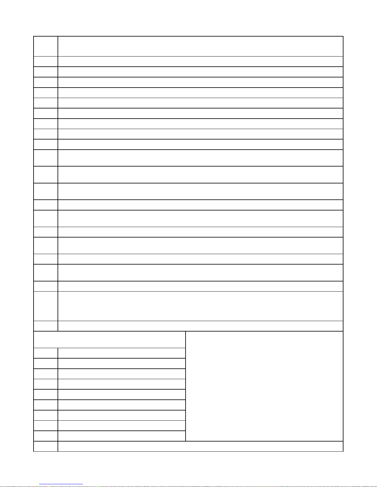
FAULT CODE TABLE
Fault
Code
Description of Condition
0 Normal
1 Communication Fault - Overrun Error reading incoming message.
2 Communication Fault - Time out error reading incoming message.
3 Communication Fault - Time out error responding to message.
4 Communication Fault - Incoming message failed Checksum Test.
5 Communication Fault - Invalid Modbus Function Code.
6 Communication Fault - Trying to preset more than 35 registers using Function Code No. 16.
7 Communication Fault - Trying to force to more than 100 Coils using Function Code No. 15.
8 Parameter Setup Fault - More than one Discrete Input is assigned to the same Function.
Parameter Setup Fault - Pump On & Pump Off parameters are set too close together. (They must be at least
9
0.2 feet apart with P.36 = 1, or 2 feet apart with P.36 = 0, or 0.02 feet apart with P.36 = 2.)
10
11
12 VFD Speed Reference Setup Fault - Level at Minimum Speed and Level at 100% speed are backwards.
13
14 Communication Fault - Noise Detected on incoming message.
15
16 Pump Operation on Float Backup.
17
18 All Pump Disable - Discrete Input programmed for Function 8 is closed (Typically connected to Phase Monitor).
19
20 Level Probe Fault - Test Signal Status Below Normal Range. See Parameter L.11 on page 7.
21 Electrode 1 Covered before Electrode 2
22 Electrode 2 Covered before Electrode 3
23 Electrode 3 Covered before Electrode 4
24 Electrode 4 Covered before Electrode 5
25 Electrode 5 Covered before Electrode 6
26 Electrode 6 Covered before Electrode 7
27 Electrode 7 Covered before Electrode 8
28 Electrode 8 Covered before Electrode 9
29 Electrode 9 Covered before Electrode 10
30 Pump(s) are Called to Operate by the Level Probe Backup Pump Control.
Parameter Setup Fault - Pump On & Pump Off parameters are upside down. (Pump Off Level must be lower
than the Pump On Level, for a pump down application.)
VFD Speed Reference Setup Fault - Level at Minimum Speed is set too close to Level at 100% speed. (They
must be at least 0.5 feet apart with P.36 = 1, or 5 feet with P.36 = 0, or 0.05 feet with P.36 = 2.)
Communication Fault - The UART detected a Framing Error reading the incoming message. It did not find Stop
Bit where expected.
Normal Pump Operation Disabled - Discrete Input programmed for Function 31 is closed. Pump Operation will
only be allowed from Float Backup or Level Probe Backup.
Backup Float Switch Out of Sequence.
Note: Fault will clear when normal operation is verified.
One of the Pump On or Pump Off level control Parameters (or Parameters P.21, P.22, P.42, or P43) is set too
low. One of them is set in the part of the display range that is artificially created by the Level Offset Parameter
F.21. See page 5 for a description of Parameter F.21. All level control Parameters must be set higher than what
is set on Parameter F.21.
Fault Codes 21 - 29 Level Probe Fault
Electrodes Covered Out of Sequence
Notes:
Level Probe Fault Codes 21-29 must be present for at
1.
least 60 seconds for the fault to be latched into memory.
2. To reset the fault, scroll to and view Parameter FLC. Record the Fault Code, then press the Down push-button
while viewing the Fault Code. Cycling power to the controller will also reset the Fault Code.
3. The analog value associated with each of the Level Probe
Electrodes may be viewed from Parameters L.01 - L.10.
See page 7.
18
Page 20
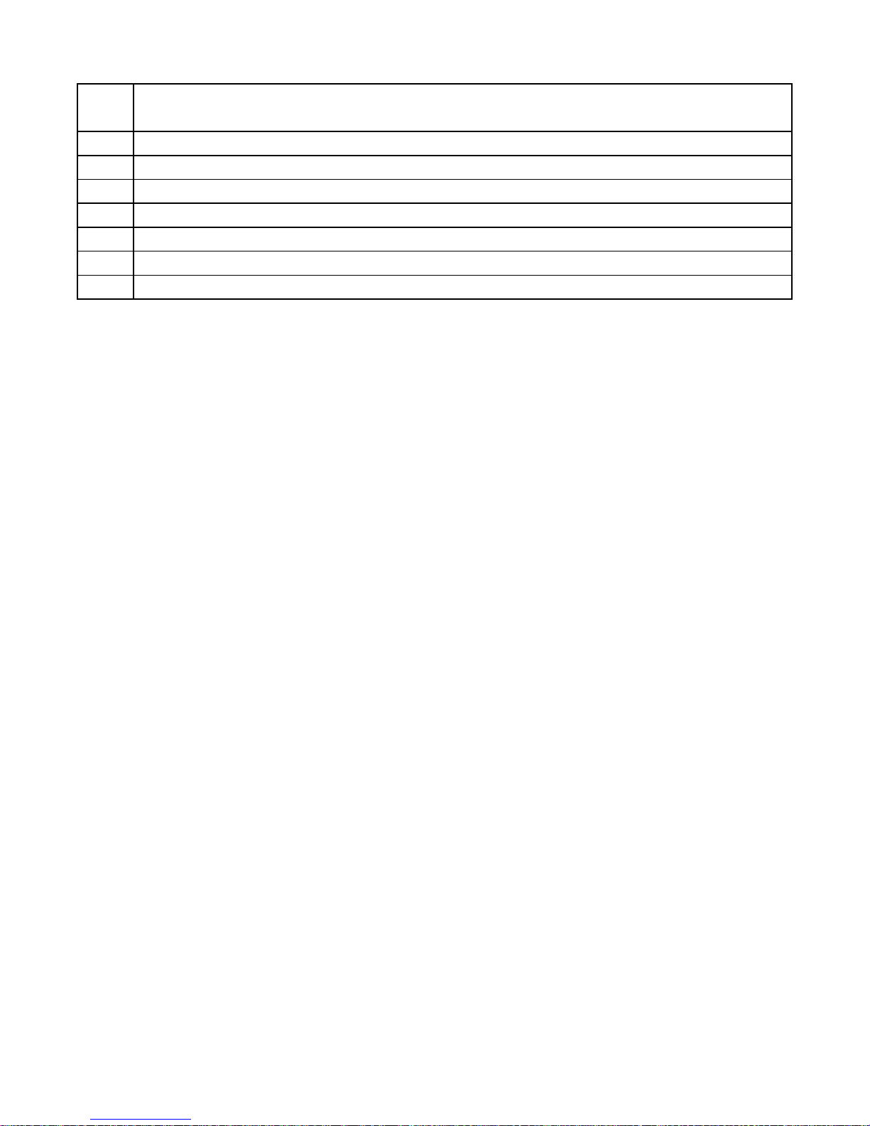
FAULT CODE TABLE
Fault
Code
Description of Condition
31 Communication Fault - Write Attempt to Register Not Marked for “Write” using Function Code No. 05.
32 Communication Fault - Write Attempt to Register Not Marked for “Write” using Function Code No. 06.
33 Communication Fault - Write Attempt to Register Not Marked for “Write” using Function Code No. 15.
34 Communication Fault - Write Attempt to Register Not Marked for “Write” using Function Code No. 16.
35 Communication Fault - Write Attempt made with Register Access Mode Parameter set for Read Only.
36 Flow Calculator Setup Fault - Average Daily Inflow Total is too Large to Display. Set Parameter P.45 = 2.
37 Communication Lost - While Setup for Remote Level Input from SCADA (Parameter F.19 = 4).
19
Page 21
ANALOG LEVEL INPUT (4-20mA Input) – CALIBRATION PROCEDURE
The following calibration is for the 4-20mA Analog Level Input (Parameter F.19 = 1) and does not apply when a 10 Electrode
Level Probe is used (Parameter F.19 = 2 or 3).
Parameters P.24 and P.25 show the Wet Well Level, while allowing the Up & Down push-buttons to be used to change the
internal numbers involved in calculating the displayed level. Therefore, the appropriate 4-20mA signal must be applied to the
Level Input during each step of the calibration procedure.
If Parameters P.24 and P.25 show 77.7 feet in the display, then Parameter F.19 is setup to follow the Level Probe input. To
calibrate the level display when using the Level Probe, the distance between the electrodes must be set on Parameter F.20,
and Parameters P.24 and P.25 are not used.
The 4-20mA Analog Level Input signal conditioning may be slowed down or speeded up using Parameter P.49.
LEVEL INPUT ZERO - Parameter P.25
This parameter is used to make the display read zero feet of water with a Wet Well Level input of 4.0mA.
Calibration Procedure:
1. Apply a 4.0mA signal to the Wet Well Level Analog Input.
(Alternate Procedure - Pull the pressure transducer or bubbler tube out of the water.)
2. Scroll to the place in the System Setup Sub-Menu where Parameter P.25 is displayed.
3. Press the Scroll / Change mode push-button. (The Wet Well Level will be displayed.)
4. Use the Up / Down push-buttons to make the display read zero feet. Note: It is slow to change at first.
5. Perform the procedure below to calibrate the “LEVEL INPUT SPAN” Parameter.
LEVEL INPUT SPAN - Parameter P.24
This parameter is used to establish the Wet Well Level (in feet) that corresponds to an analog input of 20mA.
Calibration Procedure:
1. Apply a 20mA signal to the Wet Well Level Analog Input.
(Alternate Procedure – Subject the pressure transducer or bubbler tube to a known depth of water.)
2. Scroll to the place in the System Setup Sub-Menu where Parameter P.24 is displayed.
3. Press the Scroll / Change mode push-button. (The Wet Well Level will be displayed.)
4. Use the Up / Down push-buttons to make the display read the level (in feet of water) that your 20mA signal represents. Note: It is slow to change at first.
(Alternate Procedure – Use the Up / Down push-buttons to make the display read the number of feet of water
that the pressure transducer or the end of the bubbler tube is submerged under.)
5. Repeat the procedure above for the “LEVEL INPUT ZERO” Parameter.
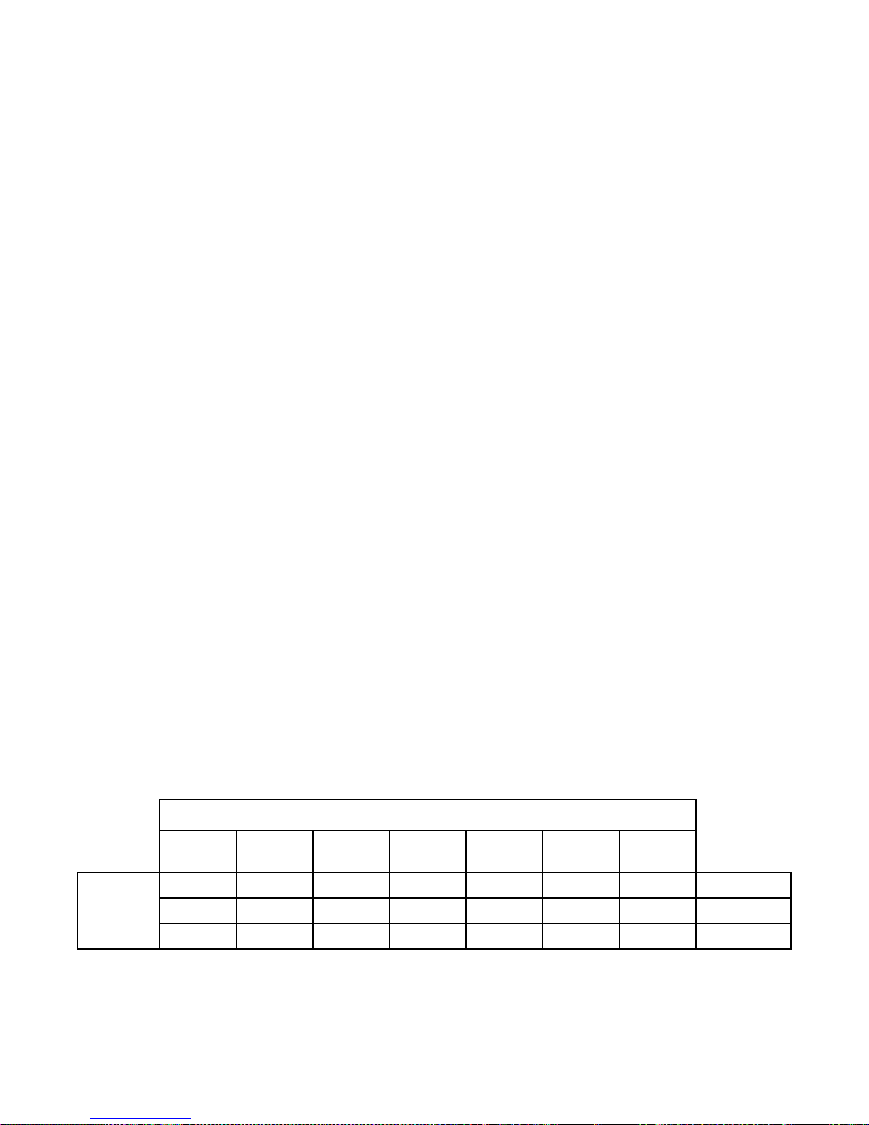
LEVEL DISPLAY SPAN VERSUS TRANSDUCER CALIBRATION
4.33psi
Level
Display
Span
@ 20mA
- - - - 139 feet 231 feet
- 11.5 feet 23.1 feet 34.6 feet - -
9.99 feet - - - - -
Notes:
1. Level Display Span is what is displayed with a 20mA Level Input.
2. Parameter P.36 is used to set the decimal point position.
3. To find the Level Input Span Setting for other transducers use the following equation:
Pressure (psi) x 2.309 = Level (feet of water)
5.0psi
@ 20mA
Transducer Calibration
10psi
@ 20mA
15psi
@ 20mA
@ 20mA
69.3 feet
20
30psi
-
-
60psi
@ 20mA
100psi
@ 20mA
P.36 = 0
P.36 = 1
P.36 = 2
Page 22
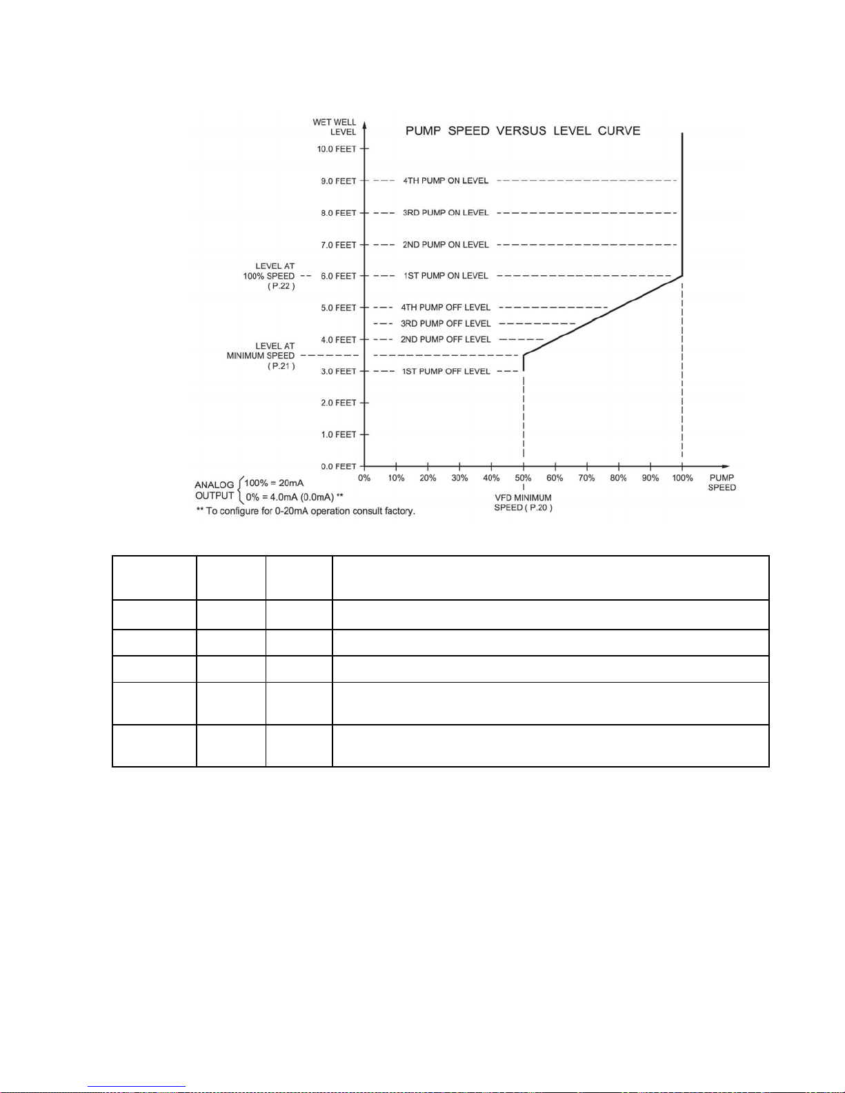
VARIABLE FREQUENCY DRIVE SPEED CONTROL OPTION SETUP
Pump Down Application - Example
VFD SPEED CONTROL - Setup Parameters
Default
Parameter
P.20
P.21
P.22
P.23
P.48
Notes:
1. A drawing should be made similar to the one above in order to coordinate the Pump Call On and Off Levels with
the Speed Versus Level Curve.
2. For each application there is usually a Minimum Speed, below which pump operation is undesirable.
3. The VFD Minimum Speed may be set on either the Pump Controller using Parameter P.20 or on the VFD, but not
on both.
4. For cases where some pumps are operated on a VFD, and others are operated at full speed, care should be taken
to setup the system so that the speed of the pumps on VFDs is not allowed to go unacceptably low while being run
with the other pumps at full speed.
5. Care should be taken not to set the Level At 100% Speed parameter and the Level At Minimum Speed Parameters
too close together. The Fault Indicator on the front of the controller will be turned on if these two Parameters are
set too close together, or are accidentally switched around. See Fault Codes 11 and 12 on the Fault Code Table.
6. Pump Start Speed Boost Time - This feature causes the Speed Reference of all pumps to temporarily increase to
100% when a pump is called, and each time an additional pump is called. The pump speed stays at 100%, for the
time set on the Parameter P.23. The pump speed then returns to normal. This feature may be used in cases
where a pump is started at a speed that is significantly less than 100%, to ensure that the Check Valve opens.
Value
50%
3.5 feet Level at Minimum Speed Range: 0.1 - 99.9 feet
6.0 feet Level at 100% Speed Range: 0.1 - 99.9 feet
0 sec.
100%
Current
Value Setting Definitions
Minimum Speed (Percent of Full Speed) Range: 0% - 95%
Pump Start Speed Boost Time Range: 0 - 60 seconds
Note: Set for 0 seconds to Disable Feature. See Note 6 below.
Speed of Pump Under Remote Control Range: 0% - 100%
SCADA Register 40046
21
Page 23
FLUSH CYCLE
The Flush Cycle feature is provided to periodically maximize the lift station’s discharge flow rate, to flush the
sludge build up from the bottom of the wet well and from the discharge pipe.
Flush Cycle Steps:
1. The “LEVEL” indicator begins to flash to indicate that the Flush Cycle has started.
2. Normal pump operation is suspended. Any pumps currently running are turned off.
3. Waits for the level to rise to the “Flush Cycle Start Level” set on Parameter P.43.
4. Turns on all available pumps with the Lag Pump Delay between each additional pump call.
5. Pumps the level down to the “Flush Cycle Stop Level” set on Parameter P.42.
6. Turns off all pumps.
7. The “LEVEL” indicator returns to normal to indicate that the Flush Cycle has ended.
Automatically Starting Flush Cycle:
A. Internal Time Delay - Expiration of “Delay Between Flush Cycles” set on Parameter P.41.
B. External Time Clock - Closure of a Discrete Input that is programmed to perform Function 39.
C. Programming the SCADA system to momentarily set Coil 139 in SCADA Register 40009.
Manually Starting / Stopping Flush Cycle:
Start - Press and hold the LEVEL Push-Button until the “LEVEL” indicator begins to flash.
(Momentarily set Coil 139 in SCADA Register 40009.)
Stop - Press and hold the LEVEL Push-Button until the “LEVEL” indicator returns to normal.
(Momentarily set Coil 140 in SCADA Register 40009.)
(Ends Flush Cycle even if it was started by the Time Delay or External Time Clock.)
Notes:
1. The Flush Cycle Feature only works in the “Pump Down” mode, (P.19 = 1). If Parameter P.19 is
2. Use of an External Time Clock to start the Flush Cycle may be preferred, because it would provide
3. Where VFDs are used the analog Speed Reference will be forced to 100%.
4. The number of pumps called to run by the Flush Cycle logic is always limited by the following:
A. Parameter P.14 - Number of Pumps Allowed to Run At the Same Time.
B. Closed Discrete Inputs that are Programmed for Pump 1 (2, 3, 4) Disable, or All Pump Disable.
5. All backup systems must be setup so that they do not activate within the Flush Cycle operating
6. The Low Level Float Backup (Discrete Input programmed for Function 32) will turn off all pumps upon
7. The Flush Cycle Status (Active or Inactive) may be read from Coil 141 in SCADA Register 40009.
changed to “Pump Up” mode (P.19 = 2), then Parameter P.40 will be set to “0”.
control over when the Flush Cycle occurs.
range set on Parameters P.42 and P.43.
low level. Therefore, the Flush Cycle Stop Level must be set higher than the Low Level Float.
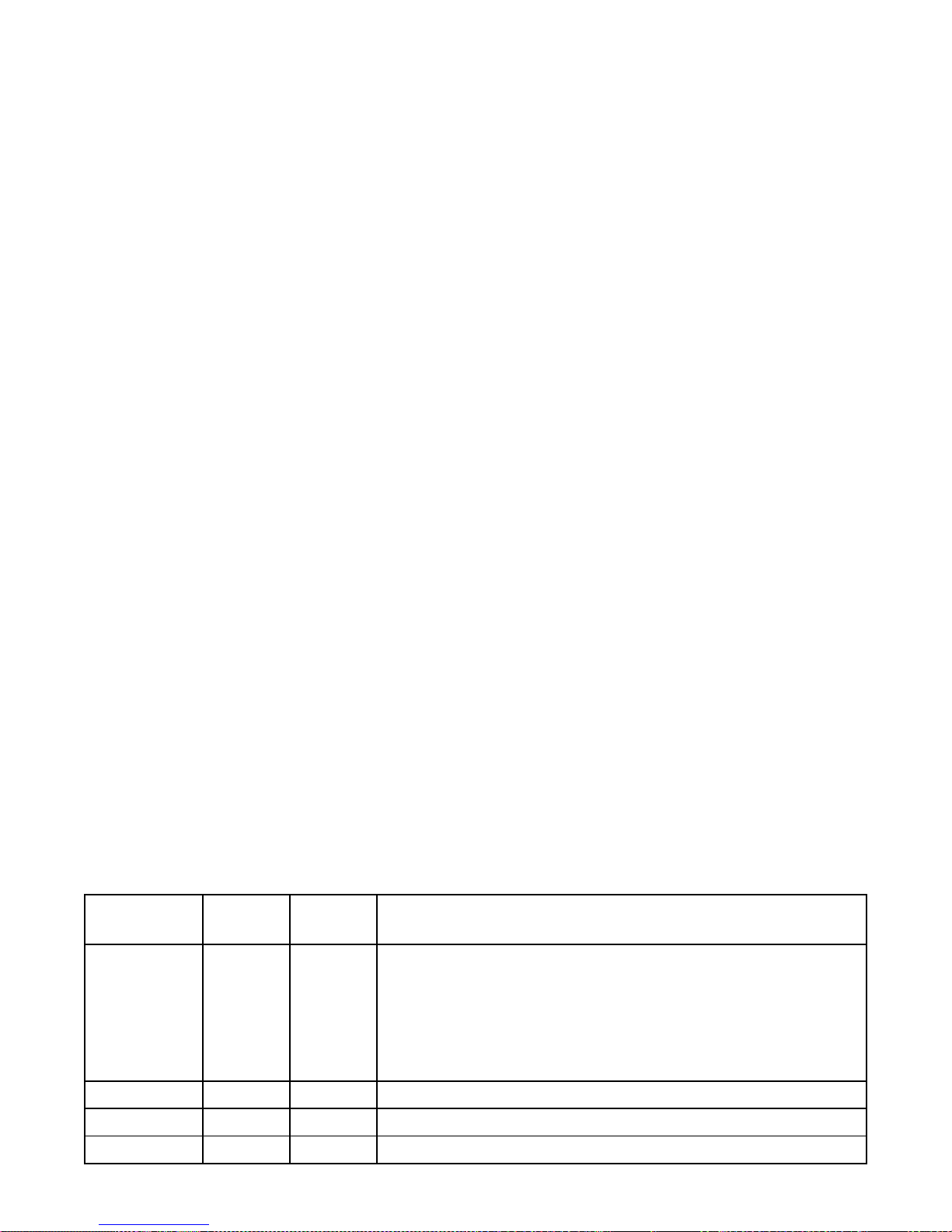
FLUSH CYCLE - Setup Parameters
Default
Parameter
P.40
P.41
P.42
P.43
Value
0
24 hours Delay Between Flush Cycles Range: 1 - 255 hours
2.5 feet Flush Cycle Stop Level Range: 0.2 - 99.9 feet
9.0 feet Flush Cycle Start Level Range: 0.2 - 99.9 feet
Current
Value Setting Definitions
Flush Cycle Mode
0 = Flush Cycle Disabled
1 = Activated by Internal Time Delay as set on Parameter P.41
2 = Activated by External Time Clock by the Closure of a Discrete
Input programmed to perform Function 39. Note: Time Clock
Contacts may stay closed indefinitely, but must re-open in order to reset logic for next Flush Cycle.
22
Page 24
FLOW CALCULATOR
Latest Inflow Rate - The Most Recently Determined Flow Rate into the Lift Station
The Flow Calculator determines the “Latest Inflow Rate” of liquid flowing into the lift station by observing
how long it takes for the wet well level to rise a “known distance”, while all pumps are off. Knowing the surface area of the wet well (Parameter P.46), the volume of liquid per minute flowing into the wet well is calculated. The “known distance” used in the calculation is a change in level of one foot when a Pressure Transducer is used (F.19 = 1), or the distance between electrodes (Parameter F.20) when using a Level Probe
(F.19 = 2or 3). The “Latest Inflow Rate”, in Gallons Per Minute, may be viewed from Parameters FLH &
FLL, and is also available for SCADA at Register 40080.
Average Daily Inflow Total - The Flow Totals from the Last 7 days Averaged Together
The Flow Calculator uses the “Latest Inflow Rate” to keep a running total of how much liquid flows into the
lift station during a 24 hour period. This is done for each 24 hour period. The flow totals from the previous
7 days are all kept stored. These flow totals are added together and divided by 7. This value is displayed
as either “Gallons Per Day” or “Thousand Gallons Per Day” (See Parameter P.45). The “Average Daily
Inflow Total” may be viewed from Parameters FdH & FdL, and is also available for SCADA at Register
40081. The 7 days of flow data are also available for SCADA at Registers 40086 - 40092.
Pump Outflow Rate - The Most Recently Determined Outflow Rate of Each Pump
The Flow Calculator determines and updates the “Pump Outflow Rate” of each pump whenever it completes a pumping cycle by itself. This is done by first calculating the volume of liquid in the wet well between the “1st On Level” and the “1st Off Level”, and adding to it what flows in while the pump is running
( “Latest Inflow Rate” multiplied by the “Pump Run Time” ). This total volume of liquid is divided by the
“Pump Run Time” to arrive at the “Pump Outflow Rate”. The most recent “Pump Outflow Rate” of each
pump in Gallons Per Minute, may be viewed from Parameters F1H & F1L, F2H & F2L, F3H & F3L, F4H &
F4L, and is also available for SCADA at Register 40082 - 40085.
Notes:
1. The Flow Calculator operates for “Pump Down - Empty a Tank” applications only, (Parameter P.19 = 1).
2. The “Average Daily Flow Total” is not valid until after 7 days of operation with Parameter P.44 = 1.
3. In order to have an accurate flow measurement the Flow Calculator must have recently acquired the “ Latest
Inflow Rate”. Since this is only acquired while all pumps are off, the station must periodically pump all the
way down, and turn off all pumps. Therefore, Parameter P.47 is provided to set the “Delay Before Forcing
On Another Pump (s)”. When this delay expires an additional pump or pumps are called to run, and the wet
well is pumped down. After calling the first additional pump, there is a 4 minute delay before another is
called.
4. While attempting to update the value of the “Latest Inflow Rate”, if the level rises too fast (faster than 1 foot
in 15 seconds, with Parameter F.19 = 1, or faster than one Level Probe Electrode spacing in 15 seconds,
with Parameter F.19 = 2 or 3, the logic aborts the measurement, and keeps the previously determined
value.
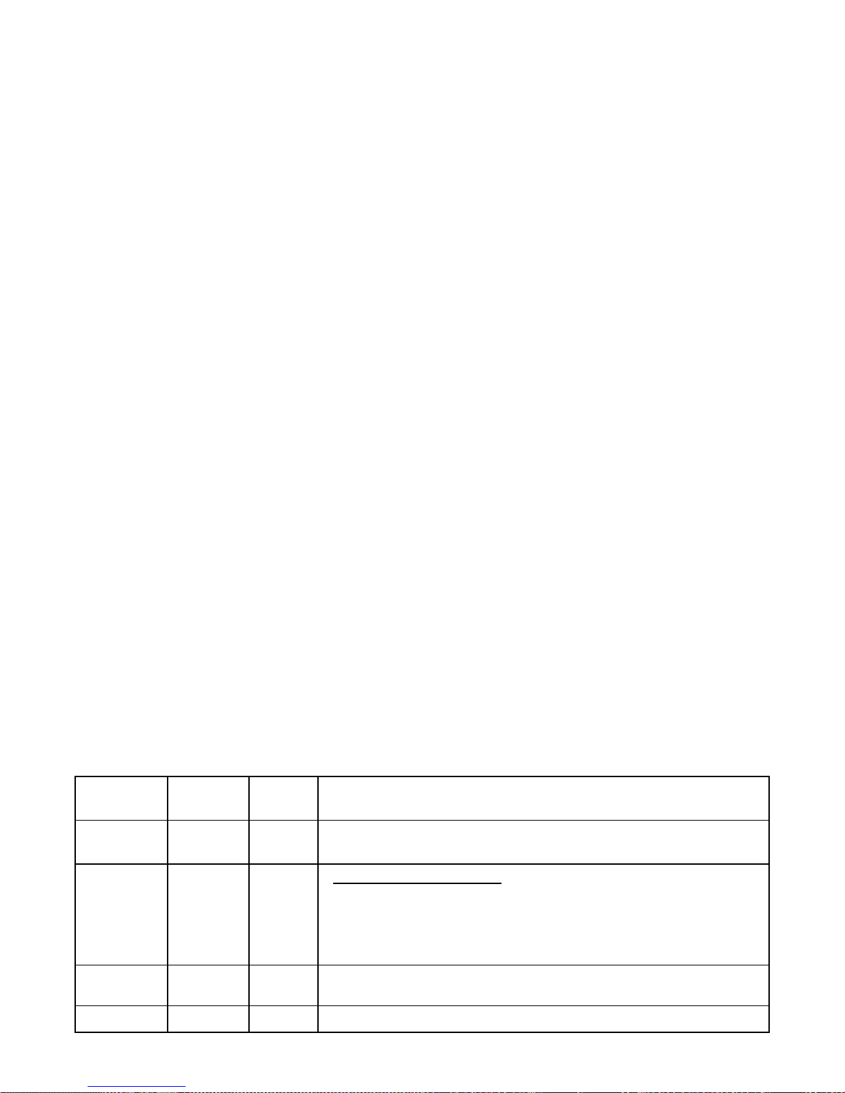
FLOW CALCULATOR - Setup Parameters
Default
Parameter
P.44
P.45
P.46
P.47
Value
0
2
79 Square
Feet
30 Minutes Delay Before Forcing On Another Pump (s)
Current
Value Setting Definitions
Surface Area of Wet Well
0 = Flow Calculator Disabled 1 = Flow Calculator Enabled
Note: All Registers that store Flow Data will be Reset to Zero if P.44 is set on 0.
Average Daily Inflow Total - Display Range
1 = 0 - 65,535 Gallons per Day
2 = 0 - 65,535 Thousand Gallons per Day
Note: Parameter P.45 also sets the Display Range of the Daily Inflow Total (Day 1 - 7)
read by SCADA at Registers 40086 - 40092.
Range: 3 - 999 Square Feet
Range: 10 - 60 Minutes
23
Page 25
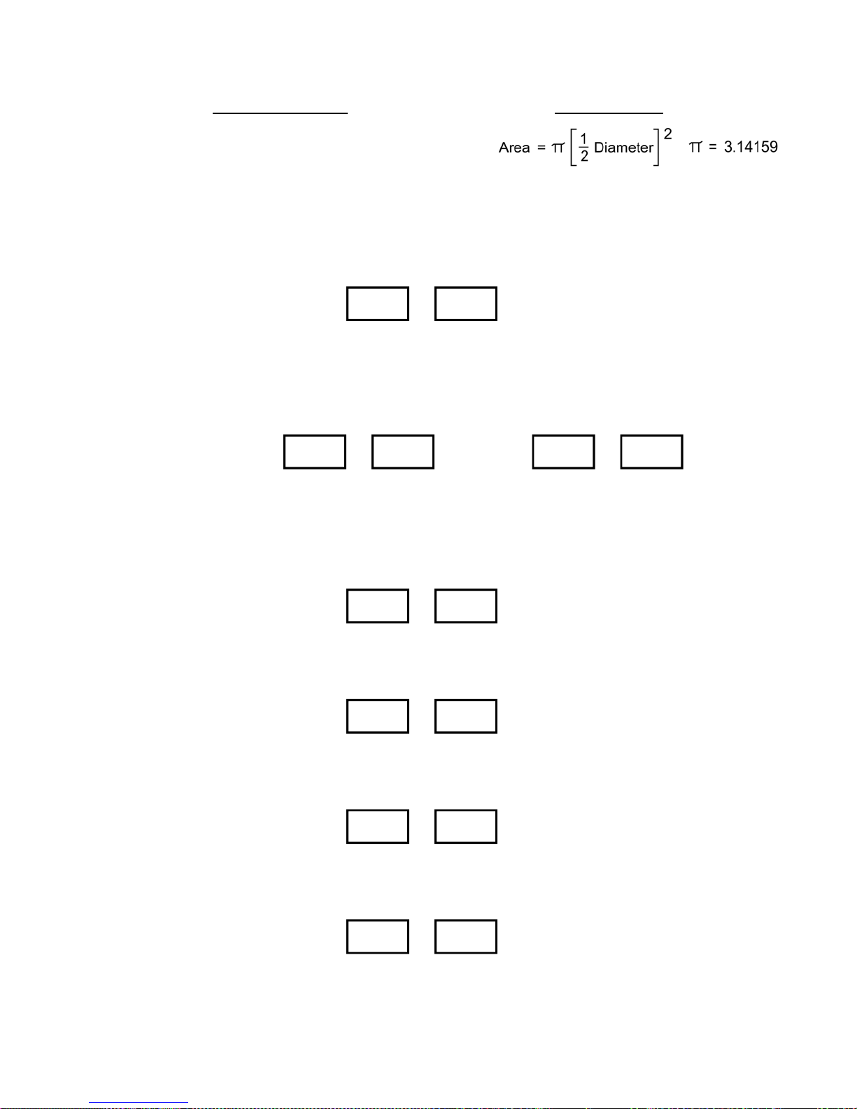
FLOW CALCULATOR - Surface Area Calculation
Area = Length x Width
Where Length & Width Measurements are in: Feet
FLOW CALCULATOR - Display Parameters
Latest Inflow Rate
Average Daily Inflow Total
With: P.45 = 1
FdH
FLH FLL
Thousand
Gallons
,
FdL
,
,
Gallons
Gallons = 7.48052 x Cubic Feet
Circular Wet Well Rectangular Wet Well
Where Diameter is in: Feet
Display Range: 0 - 65,535
SCADA Register: 40080
Per Minute
With: P.45 = 2
FdH
,
FdL
SCADA
Register:
40081
Thousand
Gallons
Note: If Fault Code 36 Appears, Average Daily Inflow Total is too Large to Display. Set Parameter P.45 = 2
Pump 1 Outflow Rate
Pump 2 Outflow Rate
Pump 3 Outflow Rate
Gallons
,
F1H F1L
Thousand
Gallons
F2H F2L
Thousand
Gallons
F3H F3L
Thousand
Gallons
Per Day
,
Gallons ,Per Minute
,
Gallons ,Per Minute
,
Gallons ,Per Minute
Million
Gallons
Thousand
,
Gallons
SCADA Register: 40082
SCADA Register: 40083
SCADA Register: 40084
Per Day
Pump 4 Outflow Rate
F4H F4L
Thousand
Gallons
SCADA Registers: 40086 - 40092 Daily Inflow Total (Day 1 - 7)
,
Gallons ,Per Minute
24
SCADA Register: 40085
Page 26
COMMUNICATION WITH A SCADA SYSTEM
A SCADA system may communicate with the controller through either the RS232 Serial Port or through the
Optional Ethernet Port. The controller operates as a MODBUS slave, where all communication is initiated
by the MODBUS master.
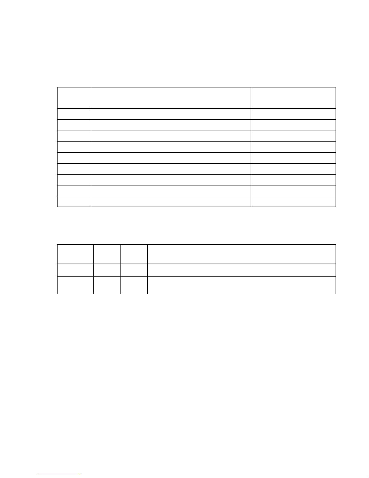
MODBUS Functions Supported
Function
Code Function Description Notes
01 Read Coil Status
02 Read Input Status
03 Read Holding Registers
04 Read Input Registers
05 Force Single Coil
06 Preset Single Register
08 Diagnostics - Sub-function 00 (Return Query Data)
15 Force Multiple Coils Limited to 100 Coils
16 Preset Multiple Registers Limited to 35 Registers
Setup for Connection to a SCADA System
efault
D
Parameter
Value Setting Definitions
P.28 1 Slave Address (See note 1 below.) Range: 0 - 247
P.33 1
Notes:
1. Each controller in a SCADA system using the Modbus protocol is assigned a unique Slave Address
so that it can be polled by the SCADA system Master using that unique Slave Address. However, if
communication is through the optional Ethernet Port, each controller will already have a unique IP
Address. When the Slave Address Parameter P.28 is set on zero, the controller will not reject messages based on the Slave Address, and it will copy the incoming Save Address for use in the Response.
2. The Register Access Mode Parameter (P.33) is provided to prevent (when set on Read Only) malicious attempts to remotely control the pumps, or change setup parameter values. Unless greatly
needed, the Register Access Mode should be left on Read & Write.
Current
Value
Register Access Mode (See note 2 below.)
1 = Read & Write 2 = Read Only
25
Page 27
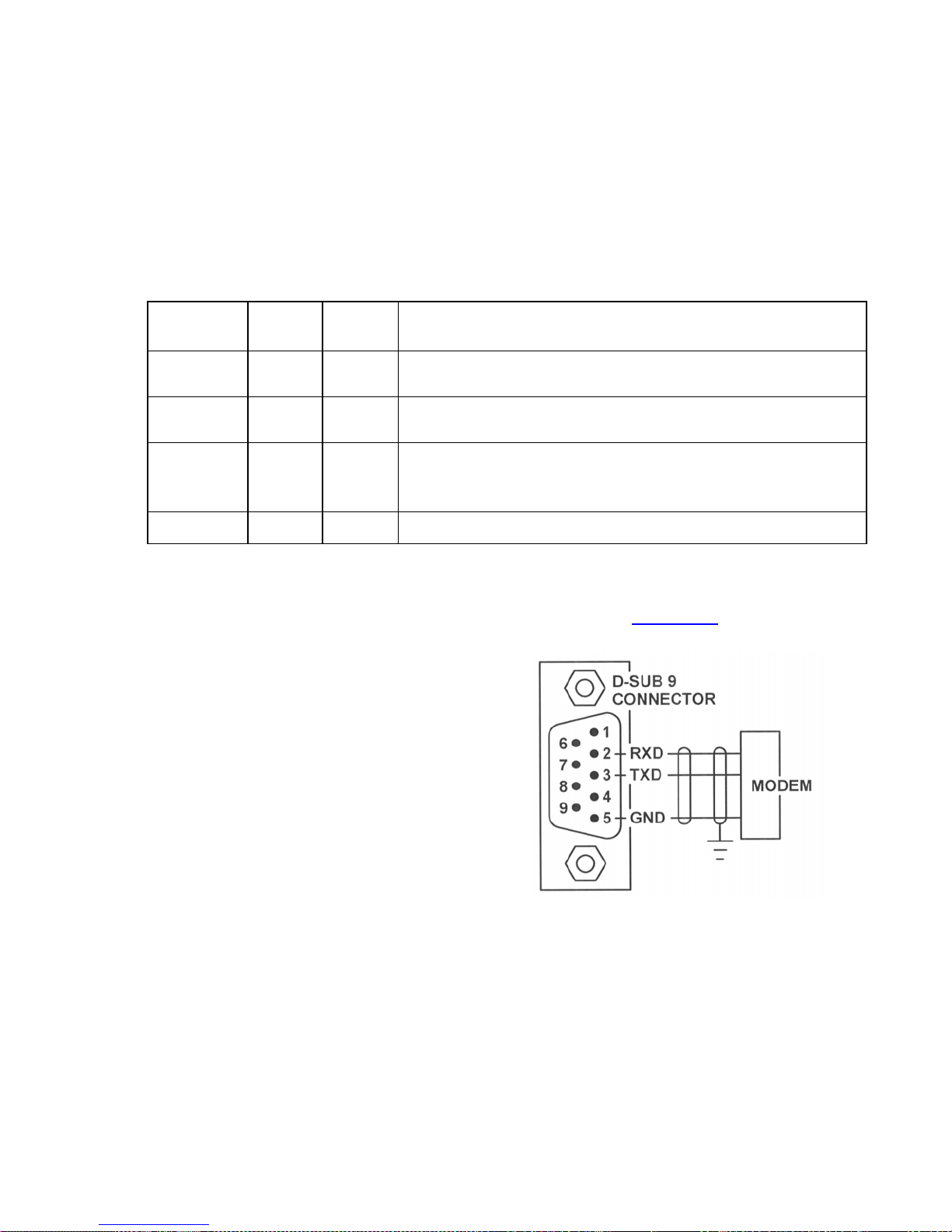
RS232 SERIAL PORT
The RS232 serial port allows a SCADA system to communicate with the Controller using the Modbus
RTU protocol.
Setup of RS232 Serial Port
The controller’s RS232 serial port must be setup to communicate with the device it is connected to. The
Baud Rate, Parity Mode and Stop Bits Parameter values of the two devices must be set to match.
The Delay Before Response Parameter (P.32) is provided for cases where the modem needs additional
time to prepare itself before receiving a response back from the controller.
Parameter
P.29 4
P.30 0
Default
Value Setting Definitions
Current
Value
Baud Rate
1 = 1200 bps 2 = 2400 bps 3 = 4800 bps 4 = 9600 bps
Parity Mode
0 = No Parity 1 = Odd Parity 2 = Even Parity
Stop Bits
P.31 2
1 = 1 Stop Bit 2 = 2 Stop Bits
(The 2nd Stop Bit is available only when No Parity is selected)
P.32 1 ms Delay Before Response Range: 1 – 100 ms
Serial Port
26
Page 28
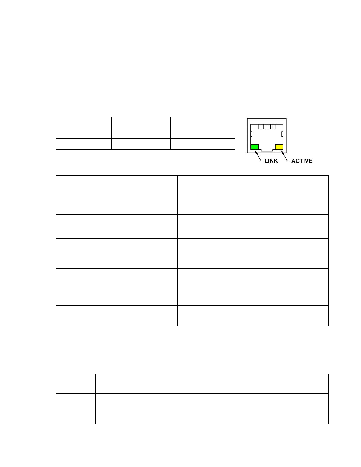
ETHERNET PORT - Option
Features
The Ethernet Port has the following features:
LED Indicator OFF ON
LINK (Green) Not Linked Linked
ACTIVE (Yellow) Idle Active Communication
Setup of Ethernet Port
Parameter Default Value
• Protocols Supported: Modbus TCP or Modbus RTU
• IEEE 802.3 Compliant
• 100 Mbps communication speed
• Full-Duplex operation
• Link, and Active status LED indicators
RJ45 Connector
Current
Value Parameter Definitions
Protocol
E.01
E.14 - E.11
E.44 - E.41
2
192 . 168 . 80 . 12
( E.14 . E.13 . E.12 . E.11 )
255 . 255 . 255 . 0
( E.44 . E.43 . E.42 . E.41 )
1 = Modbus RTU 2 = Modbus TCP
IP Address Range: 0 - 255
Identifier for the device on an IP network.
Subnet Mask Range: 0
-
255
Range of IP addresses that can be
Directly connected in the network.
Default Gateway Range: 0 - 255
A node on the network that serves as an
entrance to another network when no
E.54 - E.51
192 . 168 . 80 . 1
( E.54 . E.53 . E.52 . E.51 )
direct connection exists.
E.62 - E.61
0 , 502
( E.62 , E.61 )
Port Number
Range: 1 - 65,535
Note:
The Ethernet Port reads the setup values upon power up; any changes require the power to be cycled
before the new values are used.
Parameter Fixed Value
E.36 - E.31
0 : 80
(E.36 : E.35 : E.34 : E.33 : E.32 : E.31)
: 194 :
219 : XXX : XXX
Parameter Definition
MAC Address
Unique number that identifies each field device.
It is set at the factory, and can not be changed.
27
Page 29
SCADA REGISTERS
Register
Address
Write
Read
Description of Register Contents
(Where a Coil is represented by a Bit in a Register)
16 15 14 13 12 11 10 9 8 7 6 5 4 3 2 1
40001 √
Pump Called On
Level Probe Backup
Telemetry D
Discrete Input Function 30
Discrete Input Function 7
All Pump Disable
On Generator
Discrete Input Function 8
Telemetry C
Discrete Input Function 29
Telemetry B
Discrete Input Function 28
Pump Called On
Float Backup
Telemetry A
Discrete Input Function 27
Disabled Pump Operation
Discrete Input Function 31
Telemetry M
Discrete Input Function 26
Telemetry L
Discrete Input Function 25
Telemetry K
Discrete Input Function 24
15 14 13 12 11 10 9 8 7 6 5 4 3 2 1 0
32 31 30 29 28 27 26 25 24 23 22 21 20 19 18 17
40002 √ √
P4 Relay Remote Control
With Parameter F.36 = 2
FLC & LFC
Reset
P3 Relay Remote Control
With Parameter F.35 = 2
P2 Relay Remote Control
With Parameter F.34 = 2
P1 Relay Remote Control
With Parameter F.33 = 2
LO Relay Remote Control
With Parameter F.32 = 2
HI Relay Remote Control
With Parameter F.31 = 2
ETM 4
ETM 3
ETM 2
ETM 1
Pump 4
Force Pump On
-
-
Reset
Reset
-
-
Reset
Remote Control
Reset
15 14 13 12 11 10 9 8 7 6 5 4 3 2 1 0
40003 √ Pump 1 Elapsed Time Meter (hours and 1/10 hours) Range: 0.0
Telemetry J
Discrete Input Function 23
Force Pump On
Low Level Alarm
From All Sources
Pump 3
Pump 2
Force Pump On
Remote Control
Remote Control
-
6553.5 hours
Coil
High Level Alarm
From All Sources
Bit
Coil
Force Pump On
Pump 1
Remote Control
Bit
-
40004 √ Pump 2 Elapsed Time Meter (hours and 1/10 hours) Range: 0.0
6553.5 hours
40005 √ Pump 3 Elapsed Time Meter (hours and 1/10 hours) Range: 0.0 - 6553.5 hours
40006 √ Pump 4 Elapsed Time Meter (hours and 1/10 hours) Range: 0.0 - 6553.5 hours
128 127 126 125 124 123 122 121 120 119 118 117 116 115 114 113
All Pump Disable
1st Pump On Level Float
2nd Pump On Level Float
3rd Pump On Level Float
Low Level Float Level
Discrete Input Functions 17, 32
Discrete Input Function 34
Discrete Input Function 35
Discrete Input Function 36
4th Pump On Level Float
Discrete Input Function 37
High Level
(Level Probe Backup)
Low Level
(Level Probe Backup)
Discrete Input Functions 18, 38
Off Level Float
High Level Float
Discrete Input Function 33
On Generator
Discrete Input Function 7
Discrete Input Function 8
Telemetry H
Discrete Input Function 22
Telemetry G
Discrete Input Function 21
Telemetry F
Discrete Input Function 20
Telemetry E
Discrete Input Function 19
40008 √
15 14 13 12 11 10 9 8 7 6 5 4 3 2 1 0
144 143 142 141 140 139 138 137 136 135 134 133 132 131 130 129
Flush Cycle Active Stop Flush Cycle Start Flush Cycle
Force Alternation
Low Level (When Level is
At or Below Alarm Setting)
High Level (When Level is
At or Above Alarm Setting)
40009 √ √
Coil
Bit
Coil
15 14 13 12 11 10 9 8 7 6 5 4 3 2 1 0
Bit
28
Page 30
160 159 158 157 156 155 154 153 152 151 150 149 148 147 146 145
Pump 4 Remote Control
Disable Pump Operation
Pump 3 Remote Control
Disable Pump Operation
Pump 2 Remote Control
Disable Pump Operation
Pump 1 Remote Control
Disable Pump Operation
40010 √ √
15 14 13 12 11 10 9 8 7 6 5 4 3 2 1 0
40011 √ Wet Well Level (As shown on display with no decimal point)
40012 √ √ Setup Parameter - 1st Pump On Level
40013 √ √ Setup Parameter - 1st Pump Off Level
40014 √ √ Setup Parameter - 2nd Pump On Level
40015 √ √ Setup Parameter - 2nd Pump Off Level
40016 √ √ Setup Parameter - 3rd Pump On Level
40017 √ √ Setup Parameter - 3rd Pump Off Level
40018 √ √ Setup Parameter - 4th Pump On Level
40019 √ √ Setup Parameter - 4th Pump Off Level
40020 √ √ Setup Parameter - High Level Alarm
40021 √ √ Setup Parameter - Low Level Alarm
40022 √ √
40023 √ Current Lead Pump Position
Remote Control - Forced Lead Pump Position (Same as Parameter P.39) 0 = Alternate
1 = Pump 1 Lead 2 = Pump 2 Lead 3 = Pump 3 Lead 4 = Pump 4 Lead
40024 √ Calculated VFD Speed Reference (Percent of Full Speed, 0-100%)
40025 √ √ Remote Level Input (Must set Parameter F.19 = 4.)
560 559 558 557 556 555 554 553 552 551 550 549 548 547 546 545
Discrete
Input 8
Discrete
Input 7
Discrete
Input 6
Discrete
Input 5
40035 √
15 14 13 12 11 10 9 8 7 6 5 4 3 2 1 0
40036 √
576 575 574 573 572 571 570 569 568 567 566 565 564 563 562 561
Discrete
Input 16
Discrete
Input 15
Discrete
Input 14
Discrete
Input 13
15 14 13 12 11 10 9 8 7 6 5 4 3 2 1 0
592 591 590 589 588 587 586 585 584 583 582 581 580 579 578 577
Level Probe
Electrode 10
Level Probe
Electrode 9
Level Probe
Electrode 8
Level Probe
Electrode 7
Level Probe
Electrode 6
Level Probe
Electrode 5
Level Probe
Electrode 4
Level Probe
Electrode 3
Level Probe
Electrode 2
Level Probe
Electrode 1
Coil
Pump 4 Called to Run
Pump 3 Called to Run
Pump 1 Called to Run
Pump 2 Called to Run
Bit
Coil
Discrete
Input 4
Discrete
Input 3
Discrete
Input 2
Discrete
Input 1
Bit
Coil
Discrete
Discrete
Input 12
Discrete
Input 11
Input 9
Discrete
Input 10
Bit
Discrete
Input 18
Coil
Discrete
Input 17
40037 √
15 14 13 12 11 10 9 8 7 6 5 4 3 2 1 0
Bit
29
Page 31
40038 √ Pump 1 VFD Speed Reference, (Percent of Full Speed, 0-100%) (Same as Parameter d.03)
40039 √ Pump 2 VFD Speed Reference, (Percent of Full Speed, 0-100%) (Same as Parameter d.04)
40040 √ Pump 3 VFD Speed Reference, (Percent of Full Speed, 0-100%) (Same as Parameter d.05)
40041 √ Pump 4 VFD Speed Reference, (Percent of Full Speed, 0-100%) (Same as Parameter d.06)
40042 √ Auxiliary Analog Input 1 (8-Bit 0 - 255) (Same as Parameter n.19)
40043 √ Auxiliary Analog Input 2 (8-Bit 0 - 255) (Same as Parameter n.20)
40044 √ Auxiliary Analog Input 3 (8-Bit 0 - 255) (Same as Parameter n.21)
40045 √ Auxiliary Analog Input 4 (8-Bit 0 - 255) (Same as Parameter n.22)
40046 √ √
40047 √ Fault Code (Same as Parameter FLC)
40048 √ Last Fault Code (Same as Parameter LFC)
40049 √ Voltage of +5 Volt Power Supply (Same as Parameter d.01)
40050 √ Voltage of +24 Volt Power Supply (Same as Parameter d.02)
40063 √ Operating Program Revision Number - Controller (Same as Parameter oPr)
40071 √ Auxiliary Analog Input 1 (10-Bit 0 - 1023 )
40072 √ Auxiliary Analog Input 2 (10-Bit 0 - 1023)
40073 √ Auxiliary Analog Input 3 (10-Bit 0 - 1023)
40074 √ Auxiliary Analog Input 4 (10-Bit 0 - 1023)
40080 √ Flow Calculator - Latest Inflow Rate (Gallons Per Minute)
40081 √
40082 √ Flow Calculator - Pump 1 Outflow Rate (Gallons Per Minute)
40083 √ Flow Calculator - Pump 2 Outflow Rate (Gallons Per Minute) (Same as Param. F2H,F2L)
Remote Pump Speed Control - Only Applies to Pumps that are Remotely Forced On
By Setting Coils 17-20 (Percent of Full Speed, 0-100%) (Same as Parameter P.48)
(Same as Param. FLH,FLL)
Flow Calculator - Average Daily Inflow Total (Gallons or Thousand Gallons Per Day)
(Same as Param. FdH,FdL)
(Same as Param. F1H,F1L)
40084 √ Flow Calculator - Pump 3 Outflow Rate (Gallons Per Minute) (Same as Param. F3H,F3L)
40085 √ Flow Calculator - Pump 4 Outflow Rate (Gallons Per Minute) (Same as Param. F4H,F4L)
40086 √ Flow Calculator - Daily Inflow Total - Day 1 (Gallons or Thousand Gallons Per Day)
40087 √ Flow Calculator - Daily Inflow Total - Day 2 (Gallons or Thousand Gallons Per Day)
40088 √ Flow Calculator - Daily Inflow Total - Day 3 (Gallons or Thousand Gallons Per Day)
40089 √ Flow Calculator - Daily Inflow Total - Day 4 (Gallons or Thousand Gallons Per Day)
40090 √ Flow Calculator - Daily Inflow Total - Day 5 (Gallons or Thousand Gallons Per Day)
40091 √ Flow Calculator - Daily Inflow Total - Day 6 (Gallons or Thousand Gallons Per Day)
40092 √ Flow Calculator - Daily Inflow Total - Day 7 (Gallons or Thousand Gallons Per Day)
30
Page 32

SCADA FEATURES
Level
Level Monitoring
The Level may be monitored by reading SCADA Register 40011. The value will be just what is displayed on the front
of the controller but with no decimal point. If an operator has the Controller in the Level Simulation Mode, Register
40011 will show the simulated level.
Remote Level Input
In cases where the pumps empty or fill a remote tank, the SCADA system Master may be programmed to collect the
level data from the remote tank and write the level to SCADA Register 40025 in the Controller. For the Controller to
follow the value in Register 40025, Parameter F.19 must be set on 4. Also, the value written to Register 40025 must
already be scaled into feet as it would be displayed on the front of the Controller, but with no decimal point. The
decimal point is artificially inserted by the Controller based on Parameter P.36. For example, a level of 8.6 feet
would be written as 86 (assuming that Parameter P.36 = 1).
If SCADA communication is lost, Register 40025 will no longer receive current level data. With the loss of communication the Controller will turn off all pumps and turn on the Fault indicator and place Fault Code 37 in Parameter FLC.
The Level Display will also flash and show the last value written to Register 40025. Loss of communication is established when the delay set on Parameter P.38 expires. The time delay setting on Parameter P.38 must be set long
enough so that it will not time out during the interval between normal communication events.
Discrete Inputs
The status of all the Discrete Inputs may always be read from Coils 545 - 552 in Register 40035, Coils 561 - 568 in
Register 40036, and Coils 577 - 578 in Register 40037, regardless of what function may be assigned to the inputs.
Discrete Inputs assigned Functions 19 - 30 (Telemetry A - M) place their status in predetermined Coils, but do not perform any other function. The status of these inputs may be read from Coils in Registers 40001, and 40008.
Discrete Inputs assigned with Functions 7 - 8, 17 - 18 and 31 - 38 perform their respective function and place their status
in predetermined Coils. The status of these inputs may be read from Coils in Registers 40001, and 40008.
Auxiliary Analog Input Data
The optional Auxiliary Analog Inputs may be used to monitor such things as flow, pump speed, motor current, or whatever is connected to them. The inputs perform no control function inside the Controller. The Data may be read in either
an 8-bit or 10-bit format .
The 8-bit version of the data may be viewed on the front of the controller under Parameters n.19 - n.22.
The Data in an 8-bit format (0 - 255), may be read from Registers 40042 - 40045.
The Data in a 10-bit format (0 - 1023), may be read from Registers 40071 - 40074.
Pump On / Off and Alarm Levels
The Pump On, Pump Off, High Alarm, and Low Alarm levels may be viewed and changed at Registers 40012 - 40021.
Disabling Pump Operation
To Disable a Pump set Coil 149, 150, 151, or 152 in Register 40010. To return a pump to normal operation, clear the
respective Coil.
Upon a loss of serial communication, the Pump Disable Logic will be automatically reset, and any pump that had been
remotely disabled will be re-enabled after the delay set on Parameter P.38. For this feature to work properly, the master
must poll the Controller at intervals shorter than the time set on Parameter P.38. However, if Parameter P.38 is set on
255 the pumps will remain disabled until power is lost.
31
Page 33

SCADA FEATURES
Forcing a Pump On
To Force a Pump On set Coil 17, 18, 19, or 20 in Register 40002. To return the pump to normal operation, clear the
respective Coil.
Upon a loss of serial communication, the Force Pump On Logic will be automatically reset, and any pump that had been
remotely forced on will be turned off after the delay set on Parameter P.38. For this feature to work properly, the master
must poll the Controller at intervals shorter than the time set on Parameter P.38. However, if Parameter P.38 is set on
255 the pumps will remain on until power is lost.
Setting Speed of Pumps Forced On
To control the Speed of Pumps that are Forced On, write the desired speed in percent to Register 40046. The new
value will be stored in non-volatile EEPROM memory. The default speed is 100%. The setting may also be viewed or
changed at Parameter P.48.
Forcing Pump Alternation
To force Pump Alternation, momentarily set Coil 136 in Register 40009. When alternation is to be regularly performed
through the SCADA system, automatic alternation should be disabled by setting Parameter P.18 to equal 2.
Forcing Lead Pump Position
The Forcing of the Lead Pump Position may be accomplished by writing a 1,2,3 or 4 to Register 40022. To return to
normal alternation, write a zero to the register. Setting Register 40022 does not guarantee that the pump selected will
be lead. If the pump selected as lead is disabled (by a pump disable discrete input), then the next available pump will be
made lead. A lead pump selector switch connected to discrete inputs, programmed as sequence inputs, will also override what is written to Register 40022. The setting may also be changed at Parameter P.39. The content of Register
40022 is saved in non-volatile memory. The current lead pump position may be read from Register 40023.
Remote Control of Relays
Relays that are not needed for pump control or alarm outputs, may be controlled remotely by setting their Output Function (Parameters F.31 - 36) to 2.
Remote control is accomplished by setting or clearing Coils 25 - 30 in Register 40002.
Upon a loss of serial communication, Coils 25 - 30 will automatically be cleared after the delay set on Parameter P.38.
For this feature to work properly, the master must poll the Controller at intervals shorter than the time set on Parameter
P.38. However, if Parameter P.38 is set on 255 the relays will remain as commanded, until power is lost.
The HI Relay operates differently from the others. It has a normally closed contact, with the logic inverted. Setting Coil
25 in Register 40002 de-energizes the HI Relay closing the contact. When power is lost to the Controller the HI Relay
contact will close.
Flush Cycle
To Start Flush Cycle, momentarily set Coil 139 in Register 40009.
To Stop Flush Cycle, momentarily set Coil 140 in Register 40009.
Flush Cycle Active / Inactive status may be read from Coil 141 in Register 40009.
Flow Calculator Data
Flow Calculator Data may be read from Registers 40080 - 40092. See Pages 23 - 24.
32
Page 34

SCADA FEATURES
High Level Telemetry
The High Level Alarm is generated from a comparison of the displayed Level with the High Level alarm setting. This
alarm works when Parameter F.19 is set on either 1, 2 or 3. The status of this alarm may be read from Coil 129 in Register 40009. This alarm will also set Coil 1 in Register 40001.
The High Float Alarm is generated by the closure a float switch connected to a Discrete Input programmed for either
Function 18 or 38. The status of this alarm may be read from Coil 120 in Register 40008. This alarm will also set Coil 1
in Register 40001.
The Probe Backup High Level Alarm is generated when liquid covers the High Level Electrode of a Level Probe Input.
Parameter b.07 must be setup with the number of the Level Probe Input used to read the High Level. The status of this
alarm may be read from Coil 122 in Register 40008. This alarm will also set Coil 1 in Register 40001.
Low Level Telemetry
The Low Level Alarm is generated from a comparison of the displayed Level with the Low Level alarm setting. This
alarm works when Parameter F.19 is set on either 1, 2 or 3. The status of this alarm may be read from Coil 130 in Register 40009. This alarm will also set Coil 2 in Register 40001.
The Low Float Alarm is generated by the closure a float switch connected to a Discrete Input programmed for either
Function 17 or 32. The status of this alarm may be read from Coil 128 in Register 40008. This alarm will also set Coil 2
in Register 40001.
The Probe Backup Low Level Alarm is generated when liquid uncovers the Low Level Electrode of a Level Probe Input. Parameter b.01 must be setup with the number of the Level Probe Input used to read the Low Level. The status of
this alarm may be read from Coil 121 in Register 40008. This alarm will also set Coil 2 in Register 40001.
Fault Codes
The Fault Code (Parameter FLC) may be read from Register 40047.
The Last Fault Code (Parameter LFC) may be read from Register 40048.
The Fault Code and the Last Fault Code may be reset by setting Coil 31 in Register 40002.
Pump Speed Reference
Pump 1-4 Speed References may be read from Registers 40038 - 40041. The values are in percent of full speed (0 100%). The speed reference for a pump that is turned off is made zero, even when Parameters F.23 - 26 are set on 5.
Elapsed Time Meters
Pump 1-4 Elapsed Time Meters may be read from Registers 40003 - 40006. The values read from these registers are
intended for use in comparing the pump run time of one pump with the run time of the other pumps at the station, for the
purpose of checking for uneven run times. (Uneven run times is an indication of a maintenance problem with one of the
pumps.) Periodically the comparison of run times should be made and the registers should reset to zero. The ETM data
is stored in non-volatile memory just prior to a total loss of internal 5V power, so the data is not lost during a power outage. (However, if the serial port is being polled as a power outage occurs, the most recent data may occasionally be
lost.) To reset one of the ETMs to zero, momentarily set the respective Coil (21 - 24) in Register 40002.
33
Page 35

SCADA TROUBLESHOOTING
Communication Activity Indicator
The Communication Activity Indicator (Parameter d.07) may be used to help troubleshoot communication issues.
It typically pulses from “0” to “1” momentarily to indicate that the master is sending a message. It may stay “1” if there is
very little time between messages.
It does not indicate that a valid communication has occurred, only that there is activity on either the RS232 port or the
Ethernet port.
When using the Ethernet Port, the Ethernet Board logic will block messages with the wrong IP Address, or when there
are setup issues with the Ethernet Port. For the Activity Indicator to be pulsed, the message must be accepted and
passed through the Ethernet Board to the Main Controller Board.
Address of Last Slave Polled by Master
The Address of Last Slave Polled by Master (Parameter d.08) may be used to help troubleshoot communication issues.
When using the RS232 port, it shows the address of the last slave that was polled by the master.
When using the Ethernet Port, the Ethernet Board logic will block messages with the wrong IP Address, or when there
are setup issues with the Ethernet Port. For Parameter d.08 to show the slave address, the message must be accepted
and passed through the Ethernet Board to the Main Controller Board.
Record of Last Modbus Message
If the Slave Address is acceptable and the message does not have an Overrun Error (FLC = 1), Time Out Error (FLC =
2), Framing Error (FLC = 13), or Noise Error (FLC = 14) then the entire Modbus message will be present in data Parameters d.08 - d.86. If the Slave Address is not acceptable or if any of these errors are encountered, the rest of the
message is rejected and does not show up in Parameters d.08 - d.86. If the entire message is received (present at Parameters d.08 - d.86), it may fail the Checksum Test (FLC = 4), have an Invalid Modbus Function Code (FLC = 5), or
have one of 7 other faults (FLC = 6, 7, or 31 - 35). Failing any of these tests will cause the logic to not perform the Function and not send out a Response.
Communication Fault Codes
Communication Faults will often generate a Fault Code (Parameters FLC and LFC) that may be used to help determine
the cause of a communication problem. When this occurs the Fault Indicator will come on.
A valid communication after a Fault will zero Parameter FLC, and will make the Fault Indicator turn off, but the Fault
Code will still be available at Parameter LFC. See the Fault Code Table for the description of the communication Fault
Codes 1 - 7, 13 - 14, 31 - 35, and 37.
34
Page 36
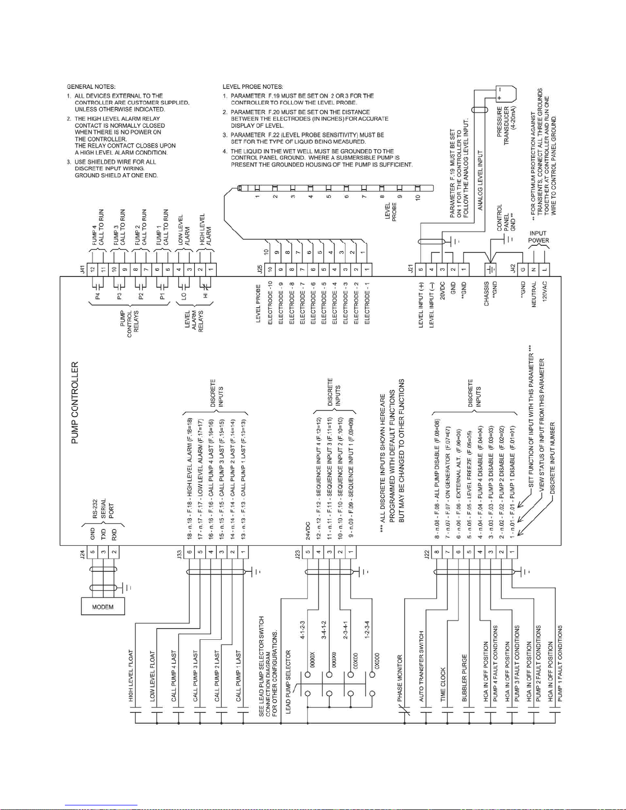
CONNECTION DIAGRAM - STANDARD FEATURES
35
Page 37
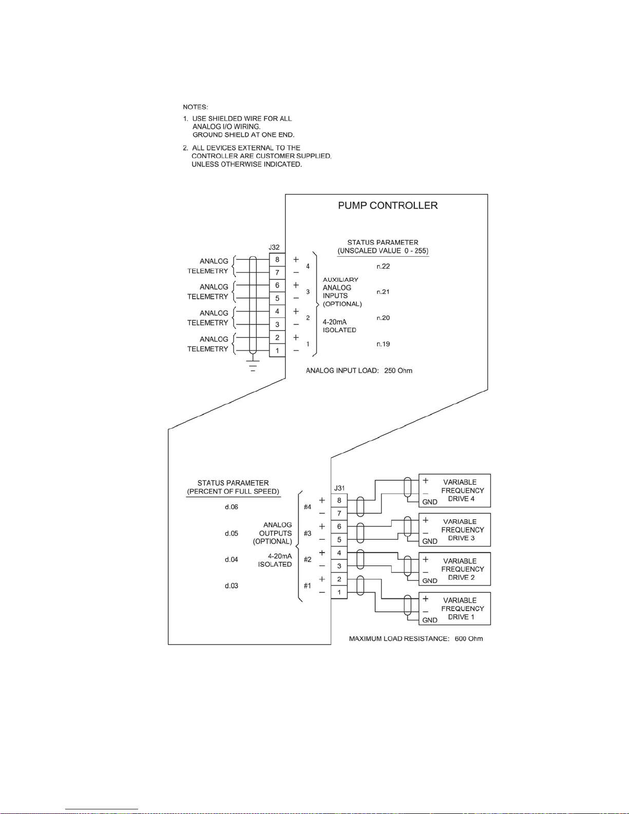
CONNECTION DIAGRAM - OPTIONAL ANALOG I/O
36
Page 38
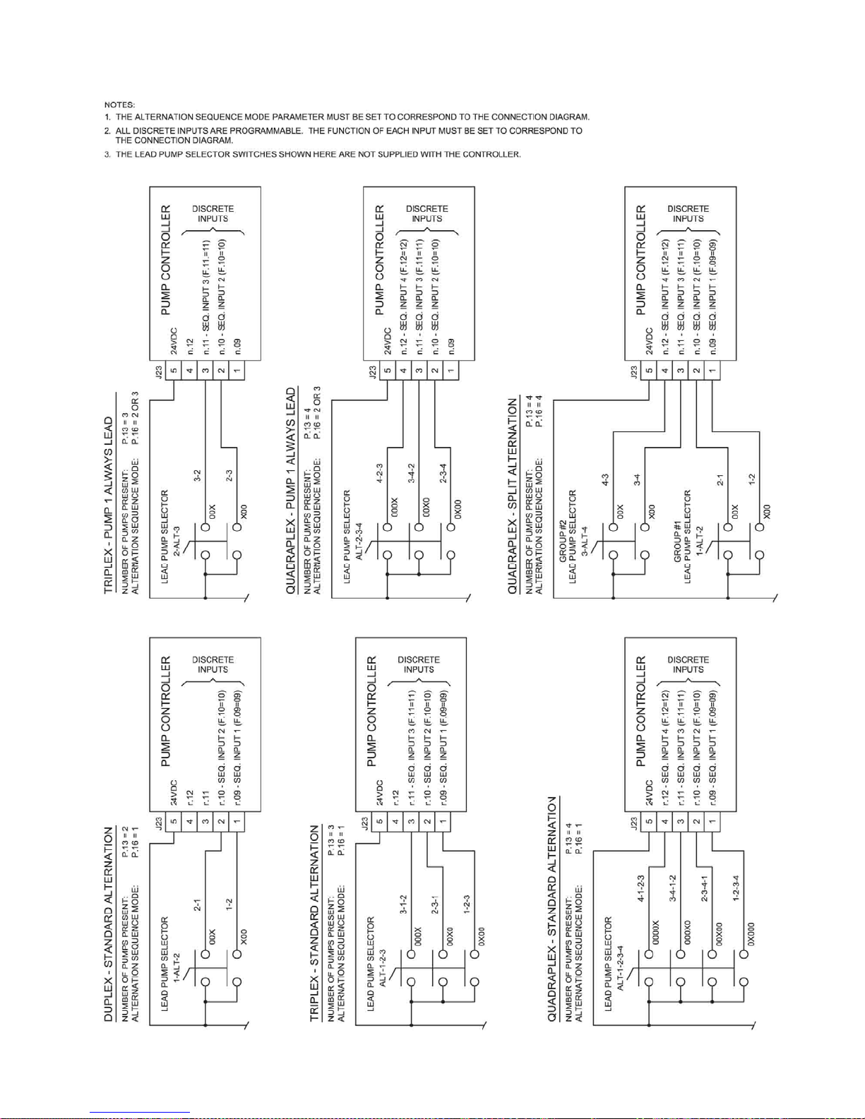
CONNECTION DIAGRAM - LEAD PUMP SELECTOR SWITCH
37
Page 39
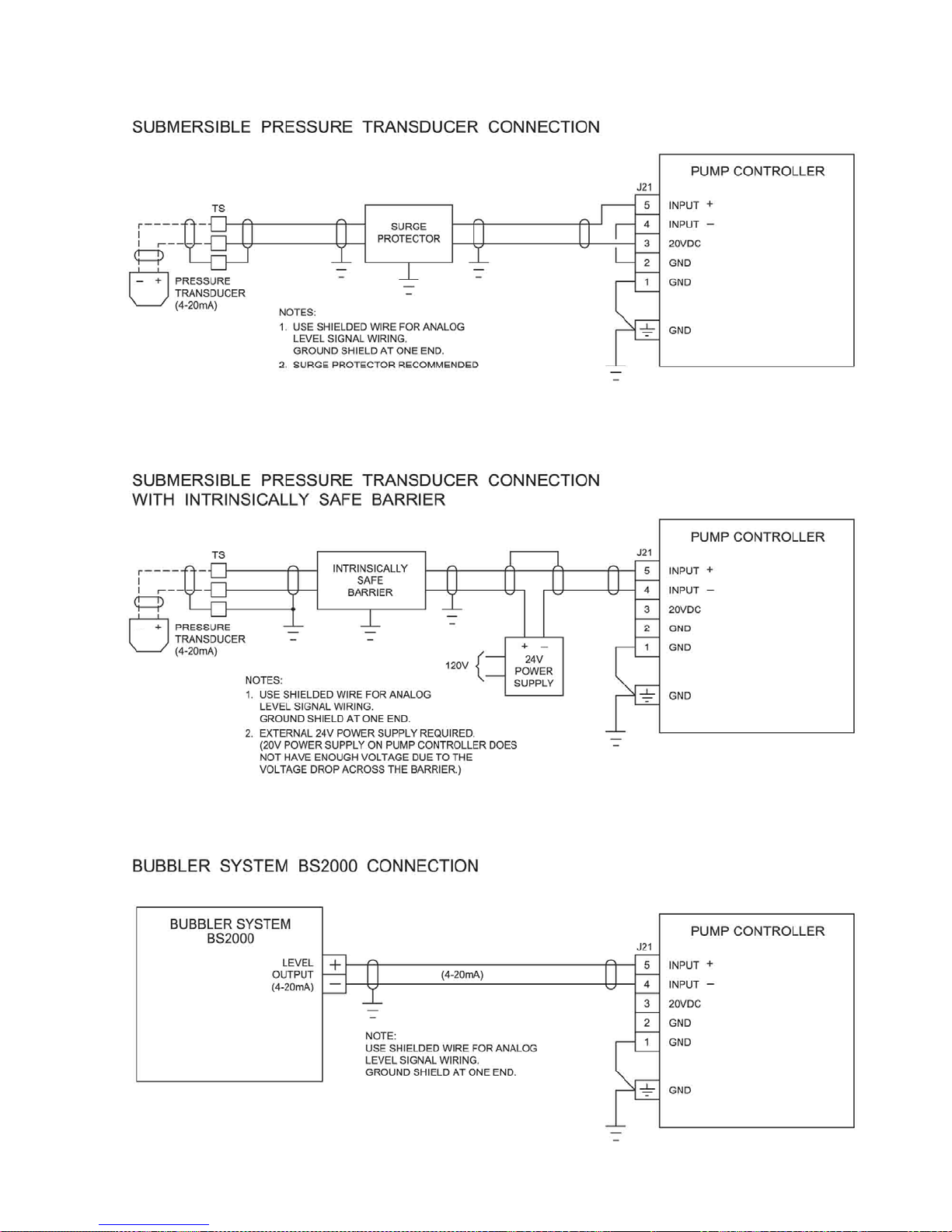
CONNECTION DIAGRAM - ANALOG LEVEL INPUT (4-20mA Input)
38
Page 40
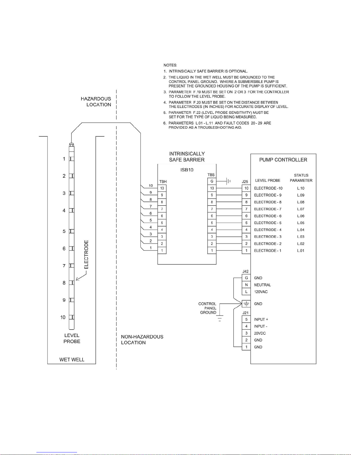
CONNECTION DIAGRAM - LEVEL PROBE
39
Page 41
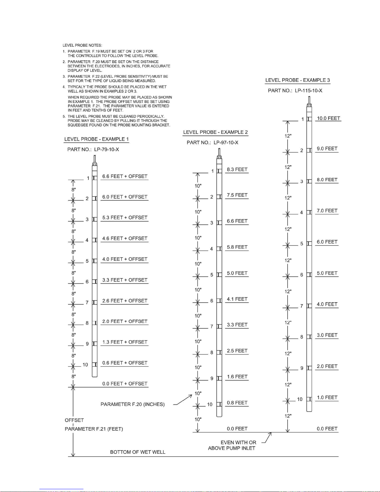
LEVEL PROBE - PLACEMENT and SETUP
40
Page 42
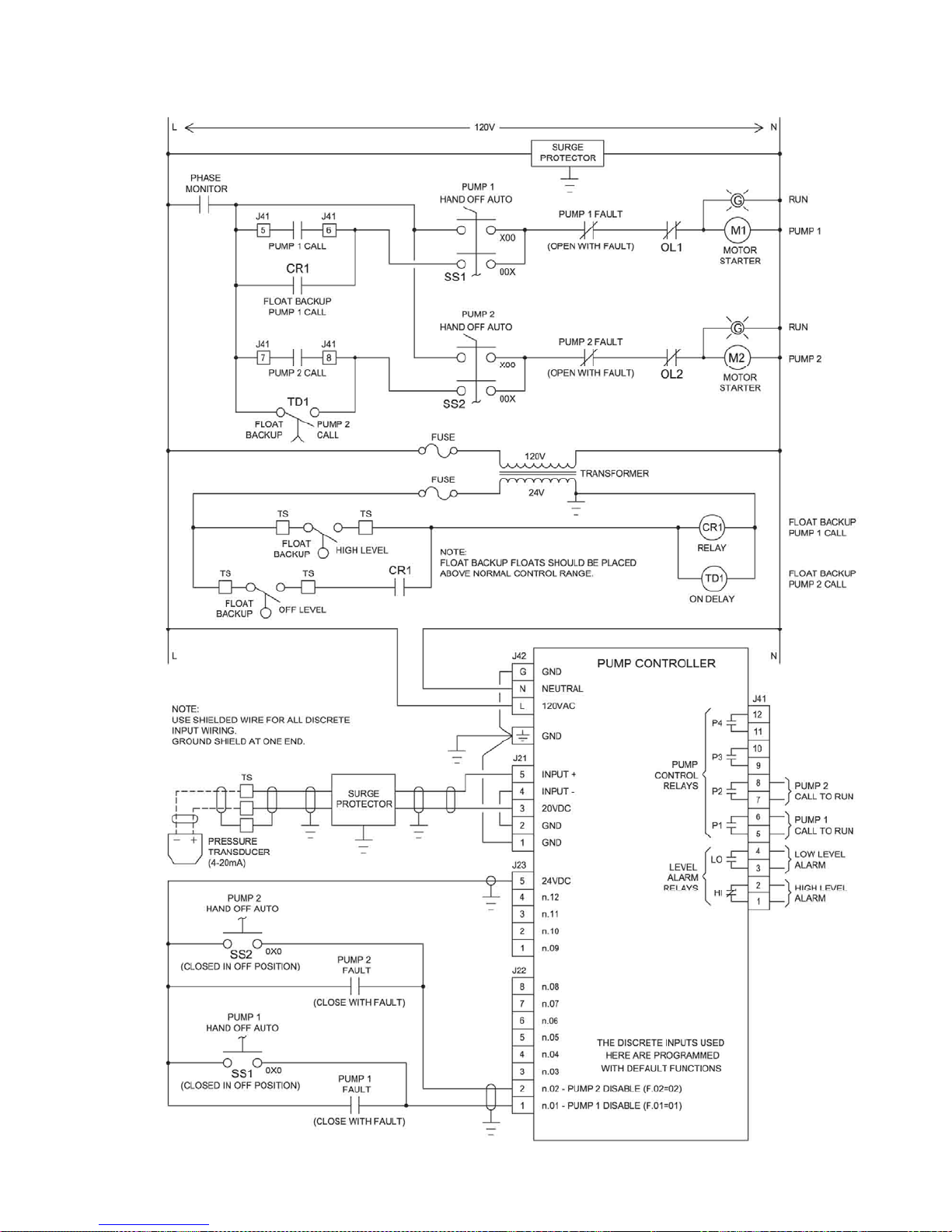
CONTROL SCHEMATIC EXAMPLE - Duplex with 24V Float Backup
41
Page 43
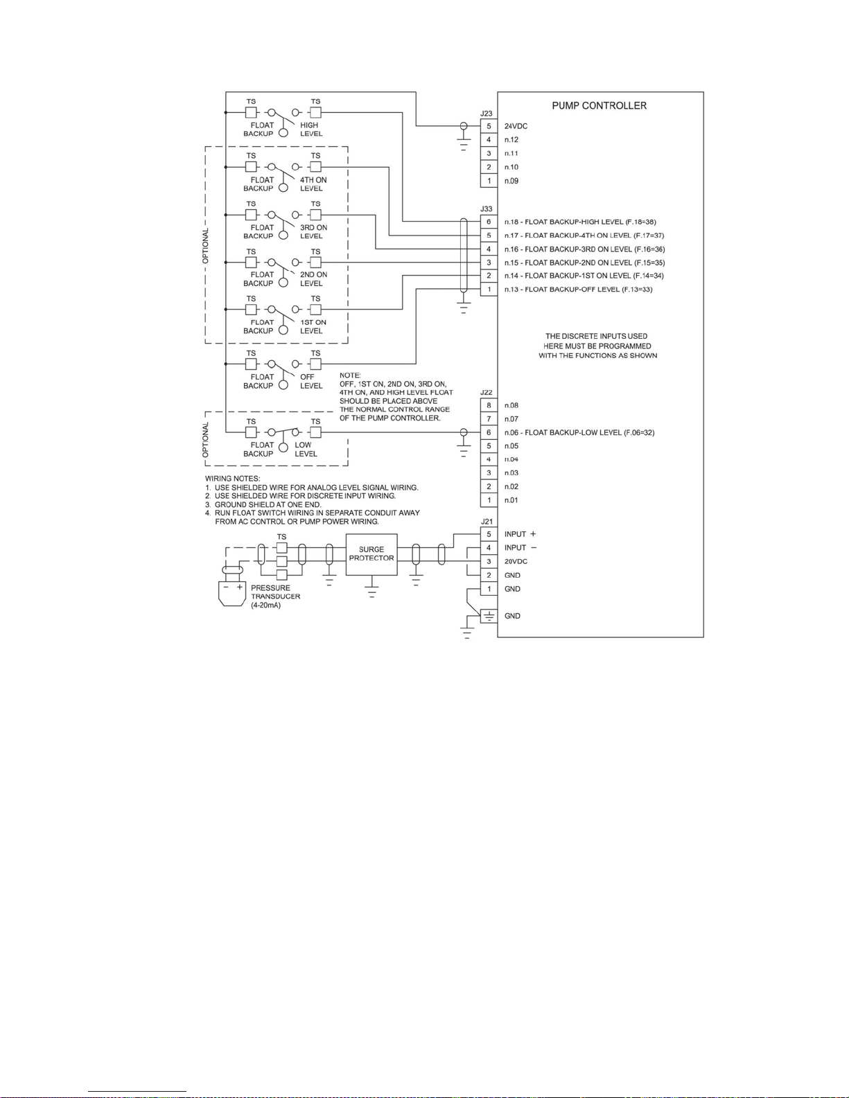
FLOAT BACKUP EXAMPLE - Pump Down
Notes:
1. Pump Down Applications (Parameter P.19 = 1)
Two Float Backup - A simple two float backup system can be made using an Off float and a High float.
High Level Input - Closure of the Float Backup High Level input will cause all pumps to be called to run, provided the
Off float input is closed. The Discrete Input used for the High Level must be set on Function 38.
Low Level input - Closure of the Low Level input will disable all pump operation. When the Low Float input opens, a
delay prevents the immediate calling of the pumps. This delay is set on Parameter P37. The Discrete Input used for
the Low Level must be set on Function 32.
Float Type - For Pump Down applications the Off, 1st , 2nd , 3rd , 4th On, and High floats must be normally open float
switches that close as the level rises above the float. The Low Level float must close as the level drops below the
float.
2. Pump Up Applications (Parameter P.19 = 2)
Two Float Backup - A simple two float backup system can be made using an Off float and a Low float.
Low Level Input - Closure of the Float Backup Low Level input will cause all pumps to be called to run, provided the
Off float input is closed. The Discrete Input used for the Low Level must be set on Function 32.
High Level Input - Closure of the High Level Float Switch will disable all pump operation. When the High Float input
opens, a delay prevents the immediate calling of the pumps. This delay is set on Parameter P37. The Discrete Input
used for the High Level must be set on Function 38.
Float Type - For Pump Up applications the Low, Off, 1st , 2nd , 3rd and 4th On floats must be normally closed float
switches that close as the level drops below the float. The High Level float must close as the level rises above the
float.
3. The FAULT light comes on and Fault Code 16 is generated, when a pump is called to run by the Float Backup system.
42
Page 44
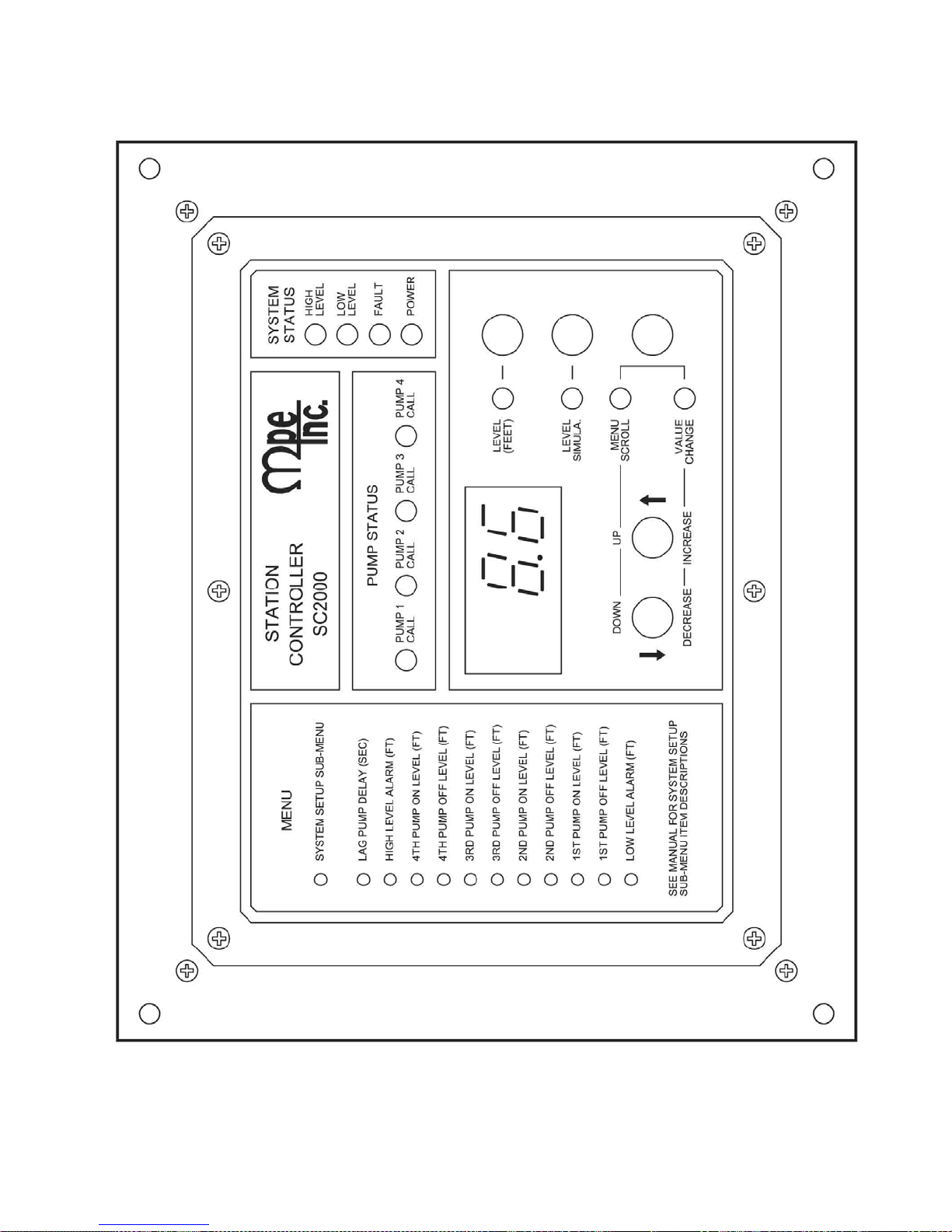
OPERATOR INTERFACE
43
Page 45
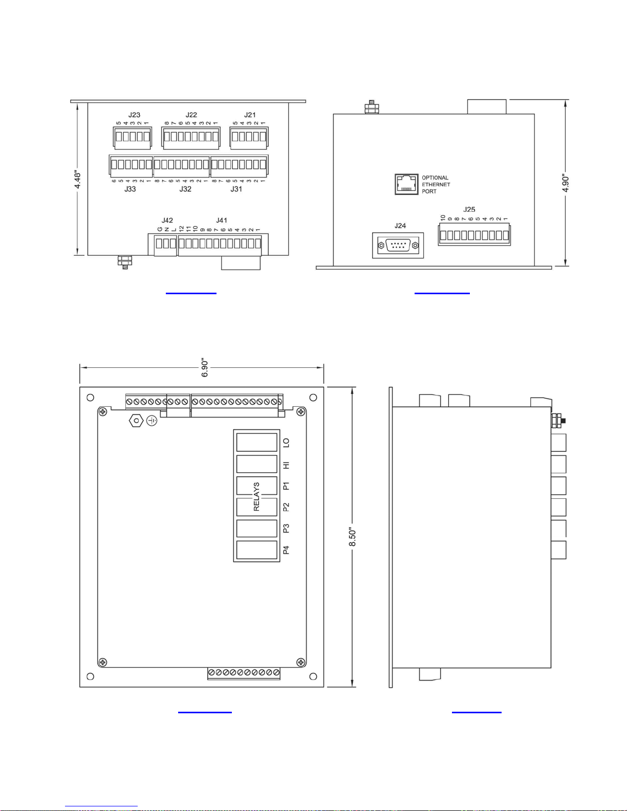
ENCLOSURE MECHANICAL LAYOUT
Left Side
Right Side
Top View Rear View
44
Page 46
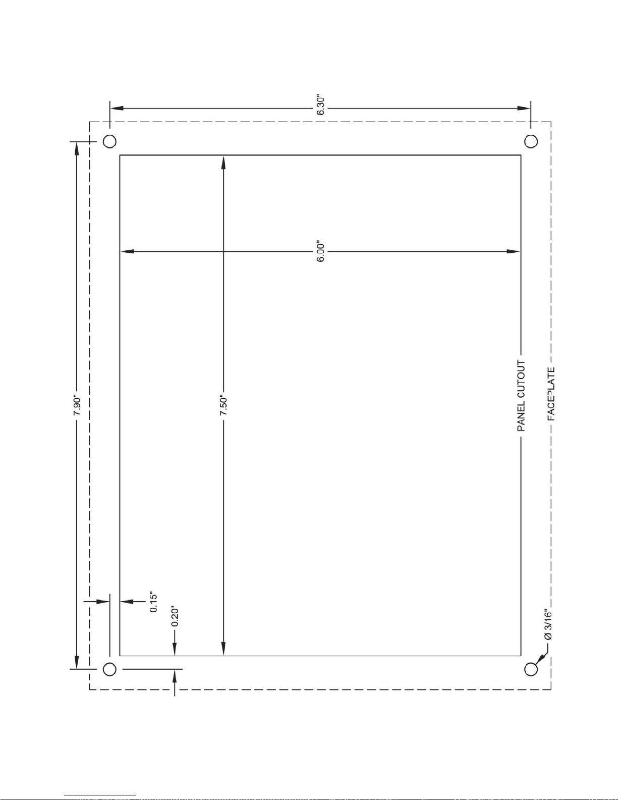
PANEL CUTOUT
Not Printed to Scale. Do Not Use as a Template.
45
 Loading...