

MPE SC100 Instruction Manual
SC100
Order from: C A Briggs Company; 622 Mary Street; Suite 101 - Warminster, PA 18974
Phone: 267-673-8117 - 800-352-6265 - Fax: 267-673-8118; E-Mail: Sales@cabriggs.com - www.cabriggs.com
SC100
SC100SC100
INSTRUCTION MANUAL
INSTRUCTION MANUAL
INSTRUCTION MANUALINSTRUCTION MANUAL
M
MOTOR
OTOR
MM
OTOROTOR
2464 Vulcan Road
Apopka, Florida 32703
P
PROTECTION
PP
ROTECTION
ROTECTIONROTECTION
E
ELECTRONICS, INC.
LECTRONICS, INC.
EE
LECTRONICS, INC.LECTRONICS, INC.
Phone:
Website:
(407) 299-3825
www.mpelectronics.com
Revision Date: 6-23-14

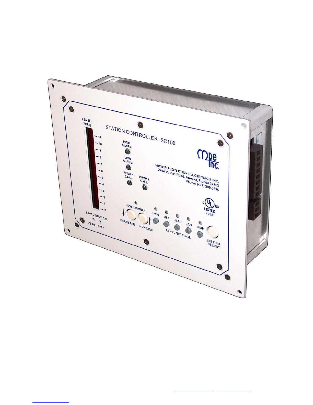
STATION CONTROLLER SC100
APPLICATIONS:
• Duplex Pumping Stations that Control Liquid Level
• Pump Down (Empty a Tank) or Pump Up (Fill a Tank) - See note by Ordering Information below
STANDARD FEATURES:
• Bar Graph Level Display - 30 segment LED
• All Level Settings may be viewed or changed from the front of the unit
• Level Input Source – Analog Level Input [4-20mA from Pressure Transducer]
May be used with 5, 10, or 15 psi Pressure Transducer when correct Scale Range is selected
See Ordering Information below
• Level Input Zero and Span Calibration
• 24VDC Power Supply for analog Level Input
• Phoenix style connectors used
• 2 Pump Call Relay outputs
• High Level and Low Level Alarm Relay outputs
• Duplex Alternation
• 10 second Power Up Delay – After a power interruption, the first pump is delayed by 10 seconds
• 5 second Lag Pump Delay – After lead pump call, lag pump call is delayed by 5 seconds
• 90 second Low Level Alarm Delay – After a power interruption, low alarm is delayed by 90 seconds
• Level Simulation – Automatically ends after 1 minute
SPECIFICATIONS:
Input Power: 120VAC +/- 10%, 7.8 VA max
Power for Analog Input: 24VDC+/- 1V, Transient Protected
Agency Approval: UL 508, CAN/CSA UL FILE #: E101681
Operating Temperature: -20 °C to +65 °C
Storage Temperature: -45 °C to +85 °C
Indicators: LED
Relay Outputs: 10A Resistive @ 120VAC
3.6A Inductive @ 120VAC
Level Analog Input: 4-20 mA, 250 Ohms Load
Transient Protected
Color: White with Blue Lettering
Enclosure Material: Aluminum
ORDERING INFORMATION:
SC100 - XX
Product Type
Scale Range
05 = 11.5 Ft/H2O
10 = 23.1 Ft/H2O
15 = 34.6 Ft/H2O
5psi Transducer used with: SC100-05
10psi Transducer used with: SC100-10
15psi Transducer used with: SC100-15
For Pump Up Applications (Fill a Tank)
add UP to Part No. after Scale Range
1
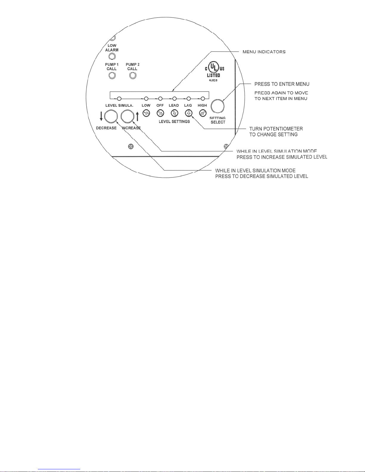
VIEW OR CHANGE LEVEL SETTINGS
Menu:
To enter the menu press the Setting Select pushbutton once. To move in the menu from left to
right, press the Setting Select pushbutton again. To exit the menu, press the Setting Select
pushbutton once while at the right most end of the menu.
Viewing Settings:
When the menu indicator over one of the Level Setting potentiometers is on, the current setting will
be shown on the bar graph display.
Changing Settings:
When the menu indicator over one of the Level Setting potentiometers is on, the potentiometer may
be turned to adjust the setting.
Note: The Off setting should be adjusted first, and then adjust the Lead and Lag settings. The
Lead and Lag settings are prevented from being too close to the Off setting. If the Off setting is
moved too close to the Lead and Lag settings, the Lead and Lag settings will be shoved away from
the Off setting and away from what is set on their respective potentiometers.
LEVEL SIMULATION
Entering Level Simulation Mode:
To enter the Level Simulation mode press the Setting Select pushbutton until the “Level Simula.“
menu indicator is turned on. Note that the Level Display bar graph will initially show what the actual
Changing the Simulated Level:
Exiting the Level Simulation Mode:
level was prior to entering the Level Simulation Mode.
To change the simulated level, press the Increase or Decrease pushbuttons as desired. The pump
1 and 2 call relays, and the high and low level alarm relays will operate just as though the water
level were actually changing.
To exit the Level Simulation mode, press the Setting Select pushbutton once. Unless you wish to
view the Level Settings continue to press the Setting Select pushbutton until all of the menu indicators are off. If the controller is left in the Level Simulation mode, a one minute timer will time out
and return the controller to normal operation. The one minute timer is reset whenever the Increase
or the Decrease pushbutton is pressed.
2
 Loading...